EP3767112B1 - Agencement de commande d'actionneur - Google Patents
Agencement de commande d'actionneur Download PDFInfo
- Publication number
- EP3767112B1 EP3767112B1 EP19315074.5A EP19315074A EP3767112B1 EP 3767112 B1 EP3767112 B1 EP 3767112B1 EP 19315074 A EP19315074 A EP 19315074A EP 3767112 B1 EP3767112 B1 EP 3767112B1
- Authority
- EP
- European Patent Office
- Prior art keywords
- actuator
- piston rod
- check valve
- housing
- valve
- Prior art date
- Legal status (The legal status is an assumption and is not a legal conclusion. Google has not performed a legal analysis and makes no representation as to the accuracy of the status listed.)
- Active
Links
Images


Classifications
-
- F—MECHANICAL ENGINEERING; LIGHTING; HEATING; WEAPONS; BLASTING
- F15—FLUID-PRESSURE ACTUATORS; HYDRAULICS OR PNEUMATICS IN GENERAL
- F15B—SYSTEMS ACTING BY MEANS OF FLUIDS IN GENERAL; FLUID-PRESSURE ACTUATORS, e.g. SERVOMOTORS; DETAILS OF FLUID-PRESSURE SYSTEMS, NOT OTHERWISE PROVIDED FOR
- F15B11/00—Servomotor systems without provision for follow-up action; Circuits therefor
- F15B11/08—Servomotor systems without provision for follow-up action; Circuits therefor with only one servomotor
-
- F—MECHANICAL ENGINEERING; LIGHTING; HEATING; WEAPONS; BLASTING
- F15—FLUID-PRESSURE ACTUATORS; HYDRAULICS OR PNEUMATICS IN GENERAL
- F15B—SYSTEMS ACTING BY MEANS OF FLUIDS IN GENERAL; FLUID-PRESSURE ACTUATORS, e.g. SERVOMOTORS; DETAILS OF FLUID-PRESSURE SYSTEMS, NOT OTHERWISE PROVIDED FOR
- F15B15/00—Fluid-actuated devices for displacing a member from one position to another; Gearing associated therewith
- F15B15/20—Other details, e.g. assembly with regulating devices
- F15B15/204—Control means for piston speed or actuating force without external control, e.g. control valve inside the piston
-
- F—MECHANICAL ENGINEERING; LIGHTING; HEATING; WEAPONS; BLASTING
- F15—FLUID-PRESSURE ACTUATORS; HYDRAULICS OR PNEUMATICS IN GENERAL
- F15B—SYSTEMS ACTING BY MEANS OF FLUIDS IN GENERAL; FLUID-PRESSURE ACTUATORS, e.g. SERVOMOTORS; DETAILS OF FLUID-PRESSURE SYSTEMS, NOT OTHERWISE PROVIDED FOR
- F15B13/00—Details of servomotor systems ; Valves for servomotor systems
- F15B13/02—Fluid distribution or supply devices characterised by their adaptation to the control of servomotors
-
- B—PERFORMING OPERATIONS; TRANSPORTING
- B64—AIRCRAFT; AVIATION; COSMONAUTICS
- B64C—AEROPLANES; HELICOPTERS
- B64C13/00—Control systems or transmitting systems for actuating flying-control surfaces, lift-increasing flaps, air brakes, or spoilers
- B64C13/24—Transmitting means
- B64C13/38—Transmitting means with power amplification
- B64C13/40—Transmitting means with power amplification using fluid pressure
- B64C13/44—Transmitting means with power amplification using fluid pressure overriding of personal controls; with automatic return to inoperative position
-
- F—MECHANICAL ENGINEERING; LIGHTING; HEATING; WEAPONS; BLASTING
- F15—FLUID-PRESSURE ACTUATORS; HYDRAULICS OR PNEUMATICS IN GENERAL
- F15B—SYSTEMS ACTING BY MEANS OF FLUIDS IN GENERAL; FLUID-PRESSURE ACTUATORS, e.g. SERVOMOTORS; DETAILS OF FLUID-PRESSURE SYSTEMS, NOT OTHERWISE PROVIDED FOR
- F15B20/00—Safety arrangements for fluid actuator systems; Applications of safety devices in fluid actuator systems; Emergency measures for fluid actuator systems
- F15B20/002—Electrical failure
-
- F—MECHANICAL ENGINEERING; LIGHTING; HEATING; WEAPONS; BLASTING
- F15—FLUID-PRESSURE ACTUATORS; HYDRAULICS OR PNEUMATICS IN GENERAL
- F15B—SYSTEMS ACTING BY MEANS OF FLUIDS IN GENERAL; FLUID-PRESSURE ACTUATORS, e.g. SERVOMOTORS; DETAILS OF FLUID-PRESSURE SYSTEMS, NOT OTHERWISE PROVIDED FOR
- F15B20/00—Safety arrangements for fluid actuator systems; Applications of safety devices in fluid actuator systems; Emergency measures for fluid actuator systems
- F15B20/004—Fluid pressure supply failure
-
- F—MECHANICAL ENGINEERING; LIGHTING; HEATING; WEAPONS; BLASTING
- F15—FLUID-PRESSURE ACTUATORS; HYDRAULICS OR PNEUMATICS IN GENERAL
- F15B—SYSTEMS ACTING BY MEANS OF FLUIDS IN GENERAL; FLUID-PRESSURE ACTUATORS, e.g. SERVOMOTORS; DETAILS OF FLUID-PRESSURE SYSTEMS, NOT OTHERWISE PROVIDED FOR
- F15B9/00—Servomotors with follow-up action, e.g. obtained by feed-back control, i.e. in which the position of the actuated member conforms with that of the controlling member
- F15B9/14—Servomotors with follow-up action, e.g. obtained by feed-back control, i.e. in which the position of the actuated member conforms with that of the controlling member with rotary servomotors
-
- B—PERFORMING OPERATIONS; TRANSPORTING
- B64—AIRCRAFT; AVIATION; COSMONAUTICS
- B64C—AEROPLANES; HELICOPTERS
- B64C13/00—Control systems or transmitting systems for actuating flying-control surfaces, lift-increasing flaps, air brakes, or spoilers
- B64C13/02—Initiating means
- B64C13/16—Initiating means actuated automatically, e.g. responsive to gust detectors
-
- B—PERFORMING OPERATIONS; TRANSPORTING
- B64—AIRCRAFT; AVIATION; COSMONAUTICS
- B64C—AEROPLANES; HELICOPTERS
- B64C9/00—Adjustable control surfaces or members, e.g. rudders
- B64C9/02—Mounting or supporting thereof
-
- F—MECHANICAL ENGINEERING; LIGHTING; HEATING; WEAPONS; BLASTING
- F15—FLUID-PRESSURE ACTUATORS; HYDRAULICS OR PNEUMATICS IN GENERAL
- F15B—SYSTEMS ACTING BY MEANS OF FLUIDS IN GENERAL; FLUID-PRESSURE ACTUATORS, e.g. SERVOMOTORS; DETAILS OF FLUID-PRESSURE SYSTEMS, NOT OTHERWISE PROVIDED FOR
- F15B2211/00—Circuits for servomotor systems
- F15B2211/30—Directional control
- F15B2211/305—Directional control characterised by the type of valves
- F15B2211/30505—Non-return valves, i.e. check valves
- F15B2211/30515—Load holding valves
-
- F—MECHANICAL ENGINEERING; LIGHTING; HEATING; WEAPONS; BLASTING
- F15—FLUID-PRESSURE ACTUATORS; HYDRAULICS OR PNEUMATICS IN GENERAL
- F15B—SYSTEMS ACTING BY MEANS OF FLUIDS IN GENERAL; FLUID-PRESSURE ACTUATORS, e.g. SERVOMOTORS; DETAILS OF FLUID-PRESSURE SYSTEMS, NOT OTHERWISE PROVIDED FOR
- F15B2211/00—Circuits for servomotor systems
- F15B2211/30—Directional control
- F15B2211/305—Directional control characterised by the type of valves
- F15B2211/3056—Assemblies of multiple valves
- F15B2211/30565—Assemblies of multiple valves having multiple valves for a single output member, e.g. for creating higher valve function by use of multiple valves like two 2/2-valves replacing a 5/3-valve
-
- F—MECHANICAL ENGINEERING; LIGHTING; HEATING; WEAPONS; BLASTING
- F15—FLUID-PRESSURE ACTUATORS; HYDRAULICS OR PNEUMATICS IN GENERAL
- F15B—SYSTEMS ACTING BY MEANS OF FLUIDS IN GENERAL; FLUID-PRESSURE ACTUATORS, e.g. SERVOMOTORS; DETAILS OF FLUID-PRESSURE SYSTEMS, NOT OTHERWISE PROVIDED FOR
- F15B2211/00—Circuits for servomotor systems
- F15B2211/30—Directional control
- F15B2211/32—Directional control characterised by the type of actuation
- F15B2211/321—Directional control characterised by the type of actuation mechanically
- F15B2211/325—Directional control characterised by the type of actuation mechanically actuated by an output member of the circuit
-
- F—MECHANICAL ENGINEERING; LIGHTING; HEATING; WEAPONS; BLASTING
- F15—FLUID-PRESSURE ACTUATORS; HYDRAULICS OR PNEUMATICS IN GENERAL
- F15B—SYSTEMS ACTING BY MEANS OF FLUIDS IN GENERAL; FLUID-PRESSURE ACTUATORS, e.g. SERVOMOTORS; DETAILS OF FLUID-PRESSURE SYSTEMS, NOT OTHERWISE PROVIDED FOR
- F15B2211/00—Circuits for servomotor systems
- F15B2211/60—Circuit components or control therefor
- F15B2211/665—Methods of control using electronic components
- F15B2211/6658—Control using different modes, e.g. four-quadrant-operation, working mode and transportation mode
-
- F—MECHANICAL ENGINEERING; LIGHTING; HEATING; WEAPONS; BLASTING
- F15—FLUID-PRESSURE ACTUATORS; HYDRAULICS OR PNEUMATICS IN GENERAL
- F15B—SYSTEMS ACTING BY MEANS OF FLUIDS IN GENERAL; FLUID-PRESSURE ACTUATORS, e.g. SERVOMOTORS; DETAILS OF FLUID-PRESSURE SYSTEMS, NOT OTHERWISE PROVIDED FOR
- F15B2211/00—Circuits for servomotor systems
- F15B2211/70—Output members, e.g. hydraulic motors or cylinders or control therefor
- F15B2211/705—Output members, e.g. hydraulic motors or cylinders or control therefor characterised by the type of output members or actuators
- F15B2211/7051—Linear output members
- F15B2211/7053—Double-acting output members
-
- F—MECHANICAL ENGINEERING; LIGHTING; HEATING; WEAPONS; BLASTING
- F15—FLUID-PRESSURE ACTUATORS; HYDRAULICS OR PNEUMATICS IN GENERAL
- F15B—SYSTEMS ACTING BY MEANS OF FLUIDS IN GENERAL; FLUID-PRESSURE ACTUATORS, e.g. SERVOMOTORS; DETAILS OF FLUID-PRESSURE SYSTEMS, NOT OTHERWISE PROVIDED FOR
- F15B2211/00—Circuits for servomotor systems
- F15B2211/80—Other types of control related to particular problems or conditions
- F15B2211/86—Control during or prevention of abnormal conditions
- F15B2211/862—Control during or prevention of abnormal conditions the abnormal condition being electric or electronic failure
- F15B2211/8623—Electric supply failure
-
- F—MECHANICAL ENGINEERING; LIGHTING; HEATING; WEAPONS; BLASTING
- F15—FLUID-PRESSURE ACTUATORS; HYDRAULICS OR PNEUMATICS IN GENERAL
- F15B—SYSTEMS ACTING BY MEANS OF FLUIDS IN GENERAL; FLUID-PRESSURE ACTUATORS, e.g. SERVOMOTORS; DETAILS OF FLUID-PRESSURE SYSTEMS, NOT OTHERWISE PROVIDED FOR
- F15B2211/00—Circuits for servomotor systems
- F15B2211/80—Other types of control related to particular problems or conditions
- F15B2211/86—Control during or prevention of abnormal conditions
- F15B2211/863—Control during or prevention of abnormal conditions the abnormal condition being a hydraulic or pneumatic failure
- F15B2211/8633—Pressure source supply failure
-
- F—MECHANICAL ENGINEERING; LIGHTING; HEATING; WEAPONS; BLASTING
- F15—FLUID-PRESSURE ACTUATORS; HYDRAULICS OR PNEUMATICS IN GENERAL
- F15B—SYSTEMS ACTING BY MEANS OF FLUIDS IN GENERAL; FLUID-PRESSURE ACTUATORS, e.g. SERVOMOTORS; DETAILS OF FLUID-PRESSURE SYSTEMS, NOT OTHERWISE PROVIDED FOR
- F15B2211/00—Circuits for servomotor systems
- F15B2211/80—Other types of control related to particular problems or conditions
- F15B2211/875—Control measures for coping with failures
- F15B2211/8752—Emergency operation mode, e.g. fail-safe operation mode
Definitions
- the present invention relates to valve arrangements for controlling a hydraulic actuator for positioning a spoiler in an aircraft.
- Hydraulic actuators find many applications, particularly in controlling movement of a moveable component.
- many moveable components and surfaces are moved by means of a hydraulic actuator.
- a hydraulic actuator comprises a cylindrical housing in which is mounted an axially moveable piston rod.
- a head of the rod inside the housing, divides the housing into two chambers each having a fluid port via which pressurised fluid can be injected into the chamber or low pressure fluid exits the chamber, so as to change the relative pressure in the two chambers either side of the piston head, thus causing movement of the piston relative to the housing.
- a free end of the piston rod that extends out of the housing is attached to a component or surface to be moved.
- Hydraulic fluid is provided to the actuator, from a hydraulic fluid supply in fluid communication with the interior of the actuator housing via the ports in the housing, to cause the piston rod to extend out of the housing, or hydraulic fluid is withdrawn from the housing to cause the piston rod to retract back into the housing.
- the movement of the piston rod is determined by the direction or and pressure of the fluid applied to the actuator, which is in response to a control signal.
- a valve is provided to set the movement to extension or retraction.
- This may be a servovalve, more specifically an electrohydraulic servovalve (EHSV).
- EHSV electrohydraulic servovalve
- the valve is positioned between the hydraulic fluid supply and the actuator and is moveable, in response to an electric control signal, between a first position in which high pressure fluid flows from the supply into one chamber of the actuator housing and low pressure fluid exits from the other chamber, and a second position in which high pressure fluid is injected into the other chamber and withdrawn from the first chamber of the actuator housing.
- the valve may also have a neutral or closed position in which fluid is neither supplied to nor withdrawn from the actuator housing.
- a spoiler is a moveable surface mounted on an aircraft wing behind the wing flap. When the aircraft is cruising, both the wing flap and the spoiler lay flat along the wing. To reduce aircraft speed, the spoiler is raised upwards relative to the wing.
- the spoiler movement is caused by a hydraulic actuator extending as described above.
- a hydraulic actuator is disclosed in US 2004/245386 .
- Another hydraulic actuator is disclosed in DE 10 2015 109513 A1 .
- the spoiler If the spoiler is extended, and pressure is lost, the spoiler will be retracted by aerodynamic load, and will gradually drop to become aligned with the wing surface until the zero hinge position is reached. It is important to keep the spoiler at this position to prevent a spurious extension.
- a 'droop' function in the spoiler using a negative stroke of the piston rod - i.e. further back into the housing than the zero position or, put another way, a stroke moving from the zero position in the opposite direction to the direction moved in the positive stroke for extending the rod.
- the droop function is used to lower the spoiler relative to the wing e.g. for high lift manoeuvers or to close a large air gap between the wing flap and the spoiler if the wing flap is extended. Droop is described in EP19305167 and EP19305168.7 .
- a problem occurs in the area of overlap of the spoiler and the wing flap ranges of motion. If, for example, electrical power driving the spoiler is lost, the spoiler will, under its own weight or under pressure from the EHSV bias, press against the wing flap when not driven by the actuator, thus interfering with movement of the wing flap if retraction is demanded. In the event of hydraulic failure, the anti-extension valve will be activated and the flap will then overcome the anti-extension threshold to be able to push on the spoiler and thus return to its neutral position.
- the inventors have, however, identified a need to provide a valve and piston assembly that allows spoiler droop - i.e. a negative stroke - whilst preventing the spoiler and flap from interfering with each other in the case of electrical failure and hydraulic failure.
- the invention provides an actuator control arrangement as defined by claim 1.
- the mechanical link may comprise a protrusion or chamfer or the like extending into the housing in the path of travel of the piston head in negative stroke, whereby at the predetermined retracted position, the piston head pushes the mechanical link to apply the mechanical input to the check valve.
- the arrangement preferably also includes an electrohydraulic servovalve (EHSV) between the pressure source and the actuator to control the direction of pressurised fluid to the actuator in response to an electric control signal.
- EHSV electrohydraulic servovalve
- the EHSV is preferably moveable between a first position in which high pressure fluid is directed from the fluid source to a first chamber of the actuator to cause extension of the piston rod and a second position whereby high pressure fluid is directed to a second chamber of the actuator to cause retraction of the piston rod with respect to the housing.
- a solenoid valve is controlled to take up a first position or a second position in response to the electric control signal, whereby when the solenoid valve is in the first position, high pressure is provided to the first port of the check valve to force the check valve to the first position, and in the second position provides a flow path for fluid from the check valve to a low pressure reservoir.
- Fig. 1 shows a hydraulic actuator 1 comprising a housing 2 and a piston comprising a piston rod 3 axially moveable in the housing 2. Movement of the piston rod 3 relative to the housing 2 is caused by providing pressurised hydraulic fluid from a fluid supply 10 to the actuator 1 via ports 4,5 in the actuator housing 2 in response to an electric control signal.
- the piston rod has a free end 3a extending out of the housing and for attachment to the surface to be moved by the actuator (not shown).
- the other end of the piston rod inside the housing 2 has a piston head 3b that extends across the diameter of the housing 2 thus dividing the housing interior into two chambers 2a,2b - one on each side of the piston head 3b.
- piston rod 3 If the piston rod 3 is to be extended out of the housing 2, high pressure fluid from a source HP is provided via a fluid line 14 into chamber 2b of the housing 2 via port 4 which causes the piston rod to move in the direction of arrow A. Fluid present in chamber 2a is thus forced from the housing 2, as the piston head moves through the housing, on the other side of the piston head, via port 5, on fluid line 15, to a reservoir (not shown) as low pressure (LP) fluid. If the piston rod 3 is to be retracted from the extended position, high pressure fluid is provided to chamber 2a via port 5 causing the piston rod 3 to move in the direction of arrow B and fluid is ejected from chamber 2b via port 4 to the reservoir.
- LP low pressure
- the direction of fluid is controlled by a EHSV valve 12 which takes up different valve positions in response to the electric control signal (not shown).
- the EHSV valve is positioned at position 12X i.e. with the lines shown in 12X aligned with the fluid lines from the supply and to the reservoir.
- the fluid lines are reversed by the EHSV valve being at position 12Y.
- the EHSV may also have a neutral position where there is no fluid flow in either direction.
- the EHSV valve is preferably biased to position 12Y via EHSV spring 122. Thus, in the event of loss of electric power, the EHSV will revert to position 12Y to avoid extension.
- an anti-extension valve 13 is provided.
- the anti-extension valve 13 is usually in position 13X allowing fluid communication between the actuator and the EHSV 12, because the fluid pressure provided at ports 131 and 132 together exceed the force of the relief valve spring 133.
- the pressure created by a tensile load at port 132 is not enough to overcome the bias of the spring 133 and so the spring pushes the anti-extension valve 13 to position 13Y which holds the piston rod at the zero position.
- end 3a of the piston rod 3 is attached to the component or surface to be moved e.g. the spoiler (not shown).
- the system is also operable in a droop mode as briefly discussed above where, in response to an electric control signal, through a solenoid valve, the actuator piston rod undergoes a negative stroke - i.e. the piston head moves away from the zero position in the opposite direction to when extending (direction B).
- the present invention therefore provides a control system for a spoiler which allows reliable operation in droop mode (negative stroke) and provides the necessary safety features in the event of loss of hydraulic and/or electric power, when the spoiler is in negative stroke or droop mode.
- the arrangement ensures that even for negative stroke of the spoiler, and in the case of electrical/hydraulic failure, the spoiler will be re-centered passively. This will permit the flap to retract without having to overcome any load in the opposite direction from the spoiler.
- the actuator 100 comprises a housing 200 within which a piston rod 300 is moveable according to the balance of pressure either side of the piston rod head 300b.
- the free end 300a of the piston rod 300 will be attached to a moveable surface e.g. the spoiler (not shown).
- the direction of movement of the piston rod 300 relative to the housing 200 (and thus whether the rod and, also, the spoiler, is extended or retracted) is determined by the direction of flow of high pressure hydraulic fluid from a supply HP.
- the actuator housing 200 has two ports 400 and 500, one either side of the neutral or zero position of the piston head in the housing. If the spoiler is to be extended and, therefore, the rod is to be extended from the housing 200, the arrangement, responsive to an electric control signal, will control high pressure fluid HP to be injected into the chamber 200b (shown to the left of Fig. 2 ) which will force the piston rod 300 in the direction of arrow A. Low pressure fluid will be ejected from port 500 at chamber 200a to the LP reservoir.
- the piston rod 300 If the piston rod 300 is to retract, then in response to the electric control signal, the high pressure fluid will be injected into chamber 200a via port 500 and this will force the piston head back into the chamber. Low pressure fluid will be ejected via port 400 back to the reservoir.
- EHSV 120 which changes position in response to the control signal.
- EHSV takes position 120X creating a fluid line from HP to port 400 and from port 500 to LP.
- EHSV takes up position 120Y so that a fluid path is created from HP to port 500 and from port 400 to LP.
- Anti-extension valve or check valve 130 operates as described above with reference to Fig. 1 whereby the usual position is 130X to complete the fluid path to port 500, but in the event of the pressure at ports 130a and 130b being less than the set force of the spring 600 (usually 1.2 times Fstall - the predetermined stall force), the spring force drives the anti-extension valve to position 130Y to prevent extension of the piston rod.
- solenoid valve 140 In active mode, as shown in Fig. 2 , the piston is in positive stroke. In this mode, solenoid valve 140 is set to position 140Y so that high pressure from source HP flows through that valve via valve line 42 forcing check valve 130, via high pressure at port 130b, to move to the right (in the drawing) to open the check valve providing a fluid path between the mode valve 150 and chamber 200b. The position of the solenoid valve 140 also provides a high pressure fluid path to the port 150a of the mode valve 150 setting it to position 150X to provide a fluid path to the servovalve 120.
- servovalve 120 when the piston is to be extended, in active (positive stroke) mode, servovalve 120 is caused to move to position 120X by the controller 160.
- High pressure fluid from source HP then flows through servovalve 120, through mode valve 150 and into chamber 200b of the actuator, pushing the piston out of the housing to the extended position. This forces fluid out of chamber 200a via port 500, through check valve 130 (via a maintenance device 45, if desired), back through mode valve 150 and servovalve to the low pressure output LP.
- the primary task of the mode valve 150 is to activate or passivate the actuator.
- This mode valve is the main device to choose between the active mode and the anti-extension mode (or droop mode when the rod is in retraction).
- the mode valve includes a damping device which becomes useful when the actuator is in droop mode. With the help of the damping function, if the actuator is moving in droop mode, it has a small resistance that avoids the phenomena called free float. This increases the stability of the wing.
- a maintenance device 45 if included, allows the possibility to depressurize the retraction chamber when the aircraft is on the ground. Without this device it would be impossible to manually extend the actuator because of the pressure entrapped in it. With the maintenance device, the aircraft maintenance crew can activate this device and extend the spoiler to be able access beneath the wing surface.
- servovalve (120) is moved to position (120Y) to exchange the high and low pressure fluid flow paths so that high pressure fluid is provided to chamber (200a) via port (500) and exits the actuator via port (400).
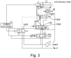
- the system takes the configuration of Fig. 3 .
- the spoiler is commanded to retain its neutral position.
- solenoid valve 140 In response to the neutral position command, solenoid valve 140 is in position 140X. There is thus no flow of high pressure from source HP to the check valve via valve line 42 and so the force of the check valve spring 130S returns the check valve to the closed position. Low pressure fluid is provided to chamber 200b at port 400 via the mode valve150 which is returned by the force of its spring 150S to position 150Y and this is balanced by the forces acting on the open side of the piston since fluid cannot flow out of chamber 200a via the closed check valve.
- a mechanical trigger (described further below) will cause the check valve to move to the right (with respect to the drawing) to take up the open position due to a mechanical link acting on port 130a of that valve. This allows the system to set to the so-called bypass mode in the event of hydraulic or mechanical failure at a given negative stroke position.
- a mechanical chamfer 800 extends into the actuator housing at a position behind the neutral position - i.e. at a position reached by the piston head when in negative stroke relative to neutral.
- the piston When the piston reaches this negative stroke position, it abuts against the chamfer 800 which, in turn, pushes the check valve against its spring bias to take up the open position 130X.
- the open position of the check valve is therefore not dependent on electric signals from the controller or on a hydraulic path as in the other modes described below.
- Signals can be provided to solenoid valve 140 via the control electronic 160s, as described above and also to the EHSV 120, to set the positions of those valves to control hydraulic flow for moving the piston but, in the case of electric or hydraulic failure, the check valve will remain open.
- the rod could, without the present invention, extend and push down on or interfere with movement of the wing flap.
- the present arrangement provides a simple, lightweight design to permit reliable droop function using existing components whilst also allowing a simple (even manual) movement of the spoiler in the event of hydraulic failure.
Landscapes
- Engineering & Computer Science (AREA)
- Physics & Mathematics (AREA)
- Fluid Mechanics (AREA)
- Mechanical Engineering (AREA)
- General Engineering & Computer Science (AREA)
- Automation & Control Theory (AREA)
- Aviation & Aerospace Engineering (AREA)
- Chemical & Material Sciences (AREA)
- Analytical Chemistry (AREA)
- Fluid-Pressure Circuits (AREA)
- Actuator (AREA)
Claims (7)
- Agencement de commande d'actionneur comprenant :un actionneur hydraulique (100) comportant un boîtier (200) et une tige de piston (300) mobile axialement à l'intérieur du boîtier entre une position neutre, une position rétractée et une position étendue par rapport au boîtier en réponse à l'application d'une pression sur la tige de piston ;une tête de piston (300b) séparant le boîtier en une première chambre (200a) pour rétracter le piston et une seconde chambre (200b) pour étendre le piston ;l'agencement comprenant également un clapet anti-retour (130) mobile entre une première position (130X) fournissant un trajet d'écoulement entre une source de pression (HP, LP) et la première chambre (200a), et une seconde position (130Y) dans laquelle le trajet d'écoulement est fermé ; etune liaison mécanique (800) entre la tige de piston et le clapet anti-retour, actionnée en réponse au passage de la tige de piston dans une position rétractée prédéterminée dans une direction de course négative, pour régler le clapet anti-retour dans la première position ;une soupape de mode (150) mobile entre une première position (150X) et une seconde position (150Y), dans lequel, dans la seconde position (150Y), la soupape de mode (150) fournit un trajet d'écoulement depuis la seconde chambre (200b) vers une source basse pression (LP) ;dans lequel l'agencement de commande d'actionneur est configuré de telle sorte que lorsque le clapet anti-retour est dans sa seconde position (130Y), la soupape de mode (150) est également dans sa seconde position (150Y) ;dans lequel le clapet anti-retour est sollicité vers la seconde position au moyen d'un ressort (130S) et comprend un premier orifice (130b) agencé pour recevoir une entrée de pression provenant d'une source de pression et un second orifice (130a) agencé pour recevoir une entrée mécanique de la liaison mécanique (800), moyennant quoi l'entrée de pression ou l'entrée mécanique est suffisante pour vaincre la force du ressort pour déplacer le clapet anti-retour vers la première position.
- Agencement de commande d'actionneur selon la revendication 1, dans lequel la liaison mécanique (800) comprend une saillie ou un chanfrein se prolongeant dans le boîtier dans le trajet de déplacement de la tige de piston (300) en course négative, moyennant quoi, à la position rétractée prédéterminée, la tige de piston (300) pousse la liaison mécanique pour appliquer l'entrée mécanique au clapet anti-retour.
- Agencement de commande d'actionneur selon une quelconque revendication précédente, comprenant également une servovalve électrohydraulique, EHSV (120) entre la source de pression et l'actionneur pour commander une direction de fluide sous pression vers l'actionneur en réponse à un signal de commande électrique.
- Agencement de commande d'actionneur selon la revendication 3, dans lequel l'EHSV (120) est mobile entre une première position dans laquelle un fluide haute pression est dirigé de la source de pression vers la première chambre (200b) de l'actionneur pour provoquer l'extension de la tige de piston et une seconde position moyennant quoi un fluide haute pression est dirigé vers la seconde chambre (200a) de l'actionneur pour provoquer la rétraction de la tige de piston par rapport au boîtier.
- Agencement de commande d'actionneur selon la revendication 3 ou 4, dans lequel la position par défaut de l'EHSV est la seconde position.
- Agencement de commande d'actionneur selon une quelconque revendication précédente, comprenant également une électrovanne (140) commandée pour prendre une première position ou une seconde position en réponse à un signal de commande électrique, moyennant quoi lorsque l'électrovanne est dans la première position, une pression élevée est fournie au premier orifice (130b) du clapet anti-retour pour forcer le clapet anti-retour vers la première position, et dans la seconde position fournit un chemin d'écoulement pour le fluide depuis le clapet anti-retour vers la source basse pression.
- Agencement de commande de spoiler pour un aéronef, comprenant un spoiler mobile par rapport à une surface d'aile et un agencement de commande d'actionneur selon une quelconque revendication précédente, l'actionneur étant agencé pour déplacer le spoiler par le mouvement de la tige de piston.
Priority Applications (5)
| Application Number | Priority Date | Filing Date | Title |
|---|---|---|---|
| EP19315074.5A EP3767112B1 (fr) | 2019-07-19 | 2019-07-19 | Agencement de commande d'actionneur |
| CA3064046A CA3064046A1 (fr) | 2019-07-19 | 2019-12-05 | Dispositif de commande d'actionneur |
| US16/709,480 US11204045B2 (en) | 2019-07-19 | 2019-12-10 | Actuator control arrangement |
| BR102019026523-0A BR102019026523B1 (pt) | 2019-07-19 | 2019-12-13 | Disposição de controle de atuador, e, disposição de controle de spoiler para uma aeronave |
| CN201911283873.7A CN112238935B (zh) | 2019-07-19 | 2019-12-13 | 致动器控制布置 |
Applications Claiming Priority (1)
| Application Number | Priority Date | Filing Date | Title |
|---|---|---|---|
| EP19315074.5A EP3767112B1 (fr) | 2019-07-19 | 2019-07-19 | Agencement de commande d'actionneur |
Publications (2)
| Publication Number | Publication Date |
|---|---|
| EP3767112A1 EP3767112A1 (fr) | 2021-01-20 |
| EP3767112B1 true EP3767112B1 (fr) | 2024-09-18 |
Family
ID=67587701
Family Applications (1)
| Application Number | Title | Priority Date | Filing Date |
|---|---|---|---|
| EP19315074.5A Active EP3767112B1 (fr) | 2019-07-19 | 2019-07-19 | Agencement de commande d'actionneur |
Country Status (4)
| Country | Link |
|---|---|
| US (1) | US11204045B2 (fr) |
| EP (1) | EP3767112B1 (fr) |
| CN (1) | CN112238935B (fr) |
| CA (1) | CA3064046A1 (fr) |
Families Citing this family (4)
| Publication number | Priority date | Publication date | Assignee | Title |
|---|---|---|---|---|
| US11852172B2 (en) * | 2022-02-18 | 2023-12-26 | Hamilton Sundstrand Corporation | Solenoid driven actuator systems |
| EP4400420B1 (fr) * | 2023-01-13 | 2026-02-04 | Goodrich Actuation Systems SAS | Gestion de protection d'arrêt d'un ema avec position negative |
| US20250044816A1 (en) * | 2023-07-31 | 2025-02-06 | Hamilton Sundstrand Corporation | Valve systems |
| CN120906864B (zh) * | 2025-10-10 | 2025-12-23 | 成都中科唯实仪器有限责任公司 | 一种触发式切换的驱动装置 |
Citations (1)
| Publication number | Priority date | Publication date | Assignee | Title |
|---|---|---|---|---|
| US20160096617A1 (en) * | 2014-10-01 | 2016-04-07 | Nabtesco Corporation | Hydraulic actuator |
Family Cites Families (11)
| Publication number | Priority date | Publication date | Assignee | Title |
|---|---|---|---|---|
| JP3141951B2 (ja) * | 1991-02-15 | 2001-03-07 | 帝人製機株式会社 | アクチュエータの中立位置復帰機構 |
| DE4414779C1 (de) | 1994-04-25 | 1995-11-02 | Mannesmann Ag | Multifunktionsventil |
| US7059563B2 (en) * | 2003-06-03 | 2006-06-13 | The Boeing Company | Systems, apparatuses, and methods for moving aircraft control surfaces |
| US7717025B2 (en) * | 2006-03-27 | 2010-05-18 | Timothy David Webster | Fluid actuator with limit sensors and fluid limit valves |
| US8434301B2 (en) | 2010-04-16 | 2013-05-07 | Nabtesco Corporation | Local backup hydraulic actuator for aircraft control systems |
| GB201108450D0 (en) | 2011-05-20 | 2011-07-06 | Airbus Operations Ltd | Aircraft wing assembly |
| WO2015195008A1 (fr) * | 2014-06-18 | 2015-12-23 | Saab Ab | Agencement d'actionneur à fluide |
| DE102015109513A1 (de) * | 2015-06-15 | 2016-12-15 | Weber-Hydraulik Gmbh | Hydrostatische Stellschaltung sowie deren Verwendung |
| US11118610B2 (en) * | 2017-08-29 | 2021-09-14 | The Boeing Company | Low profile electro-hydrostatic actuator |
| EP3693615B1 (fr) | 2019-02-11 | 2025-10-01 | Goodrich Actuation Systems SAS | Agencement de soupape de commande d'actionneur |
| EP3693616A1 (fr) | 2019-02-11 | 2020-08-12 | Goodrich Actuation Systems SAS | Agencement de soupape de commande d'actionneur |
-
2019
- 2019-07-19 EP EP19315074.5A patent/EP3767112B1/fr active Active
- 2019-12-05 CA CA3064046A patent/CA3064046A1/fr active Pending
- 2019-12-10 US US16/709,480 patent/US11204045B2/en active Active
- 2019-12-13 CN CN201911283873.7A patent/CN112238935B/zh active Active
Patent Citations (1)
| Publication number | Priority date | Publication date | Assignee | Title |
|---|---|---|---|---|
| US20160096617A1 (en) * | 2014-10-01 | 2016-04-07 | Nabtesco Corporation | Hydraulic actuator |
Also Published As
| Publication number | Publication date |
|---|---|
| BR102019026523A2 (pt) | 2021-02-02 |
| EP3767112A1 (fr) | 2021-01-20 |
| CA3064046A1 (fr) | 2021-01-19 |
| US20210018020A1 (en) | 2021-01-21 |
| US11204045B2 (en) | 2021-12-21 |
| CN112238935A (zh) | 2021-01-19 |
| CN112238935B (zh) | 2024-10-25 |
Similar Documents
| Publication | Publication Date | Title |
|---|---|---|
| US11268542B2 (en) | Actuator control valve arrangement | |
| EP3767112B1 (fr) | Agencement de commande d'actionneur | |
| EP1565373B2 (fr) | Perfectionnement de systeme et de procede de commande de surface de commande de vol | |
| US20040245386A1 (en) | Systems, apparatuses, and methods for moving aircraft control surfaces | |
| EP3222520A1 (fr) | Actionneur hydraulique de sauvegarde local pour systèmes de commande d'aéronef | |
| CN111550469B (zh) | 致动器控制阀布置 | |
| US20220266982A1 (en) | Blade pitch control | |
| US4651955A (en) | Device for automatically controllable unloading of aircraft wings | |
| US5572918A (en) | Multi-functional valve | |
| US12392361B1 (en) | Cross-bleed safety mechanism for a linear hydraulic actuator | |
| US12525849B2 (en) | EMA droop function and stops protection management | |
| US20190161172A1 (en) | Mode valve assembly | |
| BR102019026523B1 (pt) | Disposição de controle de atuador, e, disposição de controle de spoiler para uma aeronave |
Legal Events
| Date | Code | Title | Description |
|---|---|---|---|
| PUAI | Public reference made under article 153(3) epc to a published international application that has entered the european phase |
Free format text: ORIGINAL CODE: 0009012 |
|
| STAA | Information on the status of an ep patent application or granted ep patent |
Free format text: STATUS: THE APPLICATION HAS BEEN PUBLISHED |
|
| AK | Designated contracting states |
Kind code of ref document: A1 Designated state(s): AL AT BE BG CH CY CZ DE DK EE ES FI FR GB GR HR HU IE IS IT LI LT LU LV MC MK MT NL NO PL PT RO RS SE SI SK SM TR |
|
| AX | Request for extension of the european patent |
Extension state: BA ME |
|
| STAA | Information on the status of an ep patent application or granted ep patent |
Free format text: STATUS: REQUEST FOR EXAMINATION WAS MADE |
|
| 17P | Request for examination filed |
Effective date: 20210720 |
|
| RBV | Designated contracting states (corrected) |
Designated state(s): AL AT BE BG CH CY CZ DE DK EE ES FI FR GB GR HR HU IE IS IT LI LT LU LV MC MK MT NL NO PL PT RO RS SE SI SK SM TR |
|
| RAP3 | Party data changed (applicant data changed or rights of an application transferred) |
Owner name: GOODRICH ACTUATION SYSTEMS SAS |
|
| RAP3 | Party data changed (applicant data changed or rights of an application transferred) |
Owner name: GOODRICH ACTUATION SYSTEMS SAS |
|
| STAA | Information on the status of an ep patent application or granted ep patent |
Free format text: STATUS: EXAMINATION IS IN PROGRESS |
|
| 17Q | First examination report despatched |
Effective date: 20221108 |
|
| GRAP | Despatch of communication of intention to grant a patent |
Free format text: ORIGINAL CODE: EPIDOSNIGR1 |
|
| STAA | Information on the status of an ep patent application or granted ep patent |
Free format text: STATUS: GRANT OF PATENT IS INTENDED |
|
| INTG | Intention to grant announced |
Effective date: 20240419 |
|
| RIN1 | Information on inventor provided before grant (corrected) |
Inventor name: DE CORTA, NICOLAS Inventor name: DUMONT, CHRISTIAN Inventor name: MEIGNAT, GREGORY Inventor name: MARTIN-MEYER, JOHANN |
|
| GRAS | Grant fee paid |
Free format text: ORIGINAL CODE: EPIDOSNIGR3 |
|
| GRAA | (expected) grant |
Free format text: ORIGINAL CODE: 0009210 |
|
| STAA | Information on the status of an ep patent application or granted ep patent |
Free format text: STATUS: THE PATENT HAS BEEN GRANTED |
|
| AK | Designated contracting states |
Kind code of ref document: B1 Designated state(s): AL AT BE BG CH CY CZ DE DK EE ES FI FR GB GR HR HU IE IS IT LI LT LU LV MC MK MT NL NO PL PT RO RS SE SI SK SM TR |
|
| REG | Reference to a national code |
Ref country code: GB Ref legal event code: FG4D |
|
| REG | Reference to a national code |
Ref country code: CH Ref legal event code: EP |
|
| REG | Reference to a national code |
Ref country code: IE Ref legal event code: FG4D |
|
| REG | Reference to a national code |
Ref country code: DE Ref legal event code: R096 Ref document number: 602019059028 Country of ref document: DE |
|
| REG | Reference to a national code |
Ref country code: LT Ref legal event code: MG9D |
|
| PG25 | Lapsed in a contracting state [announced via postgrant information from national office to epo] |
Ref country code: NO Free format text: LAPSE BECAUSE OF FAILURE TO SUBMIT A TRANSLATION OF THE DESCRIPTION OR TO PAY THE FEE WITHIN THE PRESCRIBED TIME-LIMIT Effective date: 20241218 |
|
| PG25 | Lapsed in a contracting state [announced via postgrant information from national office to epo] |
Ref country code: GR Free format text: LAPSE BECAUSE OF FAILURE TO SUBMIT A TRANSLATION OF THE DESCRIPTION OR TO PAY THE FEE WITHIN THE PRESCRIBED TIME-LIMIT Effective date: 20241219 Ref country code: FI Free format text: LAPSE BECAUSE OF FAILURE TO SUBMIT A TRANSLATION OF THE DESCRIPTION OR TO PAY THE FEE WITHIN THE PRESCRIBED TIME-LIMIT Effective date: 20240918 |
|
| PG25 | Lapsed in a contracting state [announced via postgrant information from national office to epo] |
Ref country code: BG Free format text: LAPSE BECAUSE OF FAILURE TO SUBMIT A TRANSLATION OF THE DESCRIPTION OR TO PAY THE FEE WITHIN THE PRESCRIBED TIME-LIMIT Effective date: 20240918 |
|
| PG25 | Lapsed in a contracting state [announced via postgrant information from national office to epo] |
Ref country code: LV Free format text: LAPSE BECAUSE OF FAILURE TO SUBMIT A TRANSLATION OF THE DESCRIPTION OR TO PAY THE FEE WITHIN THE PRESCRIBED TIME-LIMIT Effective date: 20240918 |
|
| PG25 | Lapsed in a contracting state [announced via postgrant information from national office to epo] |
Ref country code: HR Free format text: LAPSE BECAUSE OF FAILURE TO SUBMIT A TRANSLATION OF THE DESCRIPTION OR TO PAY THE FEE WITHIN THE PRESCRIBED TIME-LIMIT Effective date: 20240918 |
|
| REG | Reference to a national code |
Ref country code: NL Ref legal event code: MP Effective date: 20240918 |
|
| PG25 | Lapsed in a contracting state [announced via postgrant information from national office to epo] |
Ref country code: RS Free format text: LAPSE BECAUSE OF FAILURE TO SUBMIT A TRANSLATION OF THE DESCRIPTION OR TO PAY THE FEE WITHIN THE PRESCRIBED TIME-LIMIT Effective date: 20241218 |
|
| PG25 | Lapsed in a contracting state [announced via postgrant information from national office to epo] |
Ref country code: RS Free format text: LAPSE BECAUSE OF FAILURE TO SUBMIT A TRANSLATION OF THE DESCRIPTION OR TO PAY THE FEE WITHIN THE PRESCRIBED TIME-LIMIT Effective date: 20241218 Ref country code: NO Free format text: LAPSE BECAUSE OF FAILURE TO SUBMIT A TRANSLATION OF THE DESCRIPTION OR TO PAY THE FEE WITHIN THE PRESCRIBED TIME-LIMIT Effective date: 20241218 Ref country code: LV Free format text: LAPSE BECAUSE OF FAILURE TO SUBMIT A TRANSLATION OF THE DESCRIPTION OR TO PAY THE FEE WITHIN THE PRESCRIBED TIME-LIMIT Effective date: 20240918 Ref country code: HR Free format text: LAPSE BECAUSE OF FAILURE TO SUBMIT A TRANSLATION OF THE DESCRIPTION OR TO PAY THE FEE WITHIN THE PRESCRIBED TIME-LIMIT Effective date: 20240918 Ref country code: GR Free format text: LAPSE BECAUSE OF FAILURE TO SUBMIT A TRANSLATION OF THE DESCRIPTION OR TO PAY THE FEE WITHIN THE PRESCRIBED TIME-LIMIT Effective date: 20241219 Ref country code: FI Free format text: LAPSE BECAUSE OF FAILURE TO SUBMIT A TRANSLATION OF THE DESCRIPTION OR TO PAY THE FEE WITHIN THE PRESCRIBED TIME-LIMIT Effective date: 20240918 Ref country code: BG Free format text: LAPSE BECAUSE OF FAILURE TO SUBMIT A TRANSLATION OF THE DESCRIPTION OR TO PAY THE FEE WITHIN THE PRESCRIBED TIME-LIMIT Effective date: 20240918 |
|
| REG | Reference to a national code |
Ref country code: AT Ref legal event code: MK05 Ref document number: 1724902 Country of ref document: AT Kind code of ref document: T Effective date: 20240918 |
|
| PG25 | Lapsed in a contracting state [announced via postgrant information from national office to epo] |
Ref country code: NL Free format text: LAPSE BECAUSE OF FAILURE TO SUBMIT A TRANSLATION OF THE DESCRIPTION OR TO PAY THE FEE WITHIN THE PRESCRIBED TIME-LIMIT Effective date: 20240918 |
|
| PG25 | Lapsed in a contracting state [announced via postgrant information from national office to epo] |
Ref country code: PT Free format text: LAPSE BECAUSE OF FAILURE TO SUBMIT A TRANSLATION OF THE DESCRIPTION OR TO PAY THE FEE WITHIN THE PRESCRIBED TIME-LIMIT Effective date: 20250120 Ref country code: IS Free format text: LAPSE BECAUSE OF FAILURE TO SUBMIT A TRANSLATION OF THE DESCRIPTION OR TO PAY THE FEE WITHIN THE PRESCRIBED TIME-LIMIT Effective date: 20250118 |
|
| PG25 | Lapsed in a contracting state [announced via postgrant information from national office to epo] |
Ref country code: RO Free format text: LAPSE BECAUSE OF FAILURE TO SUBMIT A TRANSLATION OF THE DESCRIPTION OR TO PAY THE FEE WITHIN THE PRESCRIBED TIME-LIMIT Effective date: 20240918 Ref country code: SM Free format text: LAPSE BECAUSE OF FAILURE TO SUBMIT A TRANSLATION OF THE DESCRIPTION OR TO PAY THE FEE WITHIN THE PRESCRIBED TIME-LIMIT Effective date: 20240918 |
|
| PG25 | Lapsed in a contracting state [announced via postgrant information from national office to epo] |
Ref country code: ES Free format text: LAPSE BECAUSE OF FAILURE TO SUBMIT A TRANSLATION OF THE DESCRIPTION OR TO PAY THE FEE WITHIN THE PRESCRIBED TIME-LIMIT Effective date: 20240918 |
|
| PG25 | Lapsed in a contracting state [announced via postgrant information from national office to epo] |
Ref country code: EE Free format text: LAPSE BECAUSE OF FAILURE TO SUBMIT A TRANSLATION OF THE DESCRIPTION OR TO PAY THE FEE WITHIN THE PRESCRIBED TIME-LIMIT Effective date: 20240918 Ref country code: AT Free format text: LAPSE BECAUSE OF FAILURE TO SUBMIT A TRANSLATION OF THE DESCRIPTION OR TO PAY THE FEE WITHIN THE PRESCRIBED TIME-LIMIT Effective date: 20240918 |
|
| PG25 | Lapsed in a contracting state [announced via postgrant information from national office to epo] |
Ref country code: CZ Free format text: LAPSE BECAUSE OF FAILURE TO SUBMIT A TRANSLATION OF THE DESCRIPTION OR TO PAY THE FEE WITHIN THE PRESCRIBED TIME-LIMIT Effective date: 20240918 Ref country code: PL Free format text: LAPSE BECAUSE OF FAILURE TO SUBMIT A TRANSLATION OF THE DESCRIPTION OR TO PAY THE FEE WITHIN THE PRESCRIBED TIME-LIMIT Effective date: 20240918 |
|
| PG25 | Lapsed in a contracting state [announced via postgrant information from national office to epo] |
Ref country code: SK Free format text: LAPSE BECAUSE OF FAILURE TO SUBMIT A TRANSLATION OF THE DESCRIPTION OR TO PAY THE FEE WITHIN THE PRESCRIBED TIME-LIMIT Effective date: 20240918 |
|
| REG | Reference to a national code |
Ref country code: DE Ref legal event code: R097 Ref document number: 602019059028 Country of ref document: DE |
|
| PG25 | Lapsed in a contracting state [announced via postgrant information from national office to epo] |
Ref country code: DK Free format text: LAPSE BECAUSE OF FAILURE TO SUBMIT A TRANSLATION OF THE DESCRIPTION OR TO PAY THE FEE WITHIN THE PRESCRIBED TIME-LIMIT Effective date: 20240918 |
|
| PGFP | Annual fee paid to national office [announced via postgrant information from national office to epo] |
Ref country code: GB Payment date: 20250619 Year of fee payment: 7 |
|
| PGFP | Annual fee paid to national office [announced via postgrant information from national office to epo] |
Ref country code: FR Payment date: 20250620 Year of fee payment: 7 |
|
| PLBE | No opposition filed within time limit |
Free format text: ORIGINAL CODE: 0009261 |
|
| STAA | Information on the status of an ep patent application or granted ep patent |
Free format text: STATUS: NO OPPOSITION FILED WITHIN TIME LIMIT |
|
| 26N | No opposition filed |
Effective date: 20250619 |
|
| PG25 | Lapsed in a contracting state [announced via postgrant information from national office to epo] |
Ref country code: SE Free format text: LAPSE BECAUSE OF FAILURE TO SUBMIT A TRANSLATION OF THE DESCRIPTION OR TO PAY THE FEE WITHIN THE PRESCRIBED TIME-LIMIT Effective date: 20240918 |
|
| PGFP | Annual fee paid to national office [announced via postgrant information from national office to epo] |
Ref country code: DE Payment date: 20250620 Year of fee payment: 7 |
|
| PGFP | Annual fee paid to national office [announced via postgrant information from national office to epo] |
Ref country code: IT Payment date: 20250619 Year of fee payment: 7 |