EP3767100B1 - Mantelstromtriebwerk mit getriebe - Google Patents
Mantelstromtriebwerk mit getriebe Download PDFInfo
- Publication number
- EP3767100B1 EP3767100B1 EP20180729.4A EP20180729A EP3767100B1 EP 3767100 B1 EP3767100 B1 EP 3767100B1 EP 20180729 A EP20180729 A EP 20180729A EP 3767100 B1 EP3767100 B1 EP 3767100B1
- Authority
- EP
- European Patent Office
- Prior art keywords
- gear
- face width
- gas turbine
- ratio
- stage
- Prior art date
- Legal status (The legal status is an assumption and is not a legal conclusion. Google has not performed a legal analysis and makes no representation as to the accuracy of the status listed.)
- Active
Links
Images


Classifications
-
- F—MECHANICAL ENGINEERING; LIGHTING; HEATING; WEAPONS; BLASTING
- F02—COMBUSTION ENGINES; HOT-GAS OR COMBUSTION-PRODUCT ENGINE PLANTS
- F02C—GAS-TURBINE PLANTS; AIR INTAKES FOR JET-PROPULSION PLANTS; CONTROLLING FUEL SUPPLY IN AIR-BREATHING JET-PROPULSION PLANTS
- F02C7/00—Features, components parts, details or accessories, not provided for in, or of interest apart form groups F02C1/00 - F02C6/00; Air intakes for jet-propulsion plants
- F02C7/36—Power transmission arrangements between the different shafts of the gas turbine plant, or between the gas-turbine plant and the power user
-
- F—MECHANICAL ENGINEERING; LIGHTING; HEATING; WEAPONS; BLASTING
- F16—ENGINEERING ELEMENTS AND UNITS; GENERAL MEASURES FOR PRODUCING AND MAINTAINING EFFECTIVE FUNCTIONING OF MACHINES OR INSTALLATIONS; THERMAL INSULATION IN GENERAL
- F16H—GEARING
- F16H1/00—Toothed gearings for conveying rotary motion
- F16H1/02—Toothed gearings for conveying rotary motion without gears having orbital motion
-
- F—MECHANICAL ENGINEERING; LIGHTING; HEATING; WEAPONS; BLASTING
- F16—ENGINEERING ELEMENTS AND UNITS; GENERAL MEASURES FOR PRODUCING AND MAINTAINING EFFECTIVE FUNCTIONING OF MACHINES OR INSTALLATIONS; THERMAL INSULATION IN GENERAL
- F16H—GEARING
- F16H1/00—Toothed gearings for conveying rotary motion
- F16H1/28—Toothed gearings for conveying rotary motion with gears having orbital motion
-
- F—MECHANICAL ENGINEERING; LIGHTING; HEATING; WEAPONS; BLASTING
- F02—COMBUSTION ENGINES; HOT-GAS OR COMBUSTION-PRODUCT ENGINE PLANTS
- F02C—GAS-TURBINE PLANTS; AIR INTAKES FOR JET-PROPULSION PLANTS; CONTROLLING FUEL SUPPLY IN AIR-BREATHING JET-PROPULSION PLANTS
- F02C3/00—Gas-turbine plants characterised by the use of combustion products as the working fluid
- F02C3/04—Gas-turbine plants characterised by the use of combustion products as the working fluid having a turbine driving a compressor
- F02C3/06—Gas-turbine plants characterised by the use of combustion products as the working fluid having a turbine driving a compressor the compressor comprising only axial stages
-
- F—MECHANICAL ENGINEERING; LIGHTING; HEATING; WEAPONS; BLASTING
- F02—COMBUSTION ENGINES; HOT-GAS OR COMBUSTION-PRODUCT ENGINE PLANTS
- F02K—JET-PROPULSION PLANTS
- F02K3/00—Plants including a gas turbine driving a compressor or a ducted fan
- F02K3/02—Plants including a gas turbine driving a compressor or a ducted fan in which part of the working fluid by-passes the turbine and combustion chamber
- F02K3/04—Plants including a gas turbine driving a compressor or a ducted fan in which part of the working fluid by-passes the turbine and combustion chamber the plant including ducted fans, i.e. fans with high volume, low pressure outputs, for augmenting the jet thrust, e.g. of double-flow type
- F02K3/06—Plants including a gas turbine driving a compressor or a ducted fan in which part of the working fluid by-passes the turbine and combustion chamber the plant including ducted fans, i.e. fans with high volume, low pressure outputs, for augmenting the jet thrust, e.g. of double-flow type with front fan
-
- F—MECHANICAL ENGINEERING; LIGHTING; HEATING; WEAPONS; BLASTING
- F16—ENGINEERING ELEMENTS AND UNITS; GENERAL MEASURES FOR PRODUCING AND MAINTAINING EFFECTIVE FUNCTIONING OF MACHINES OR INSTALLATIONS; THERMAL INSULATION IN GENERAL
- F16H—GEARING
- F16H1/00—Toothed gearings for conveying rotary motion
- F16H1/02—Toothed gearings for conveying rotary motion without gears having orbital motion
- F16H1/04—Toothed gearings for conveying rotary motion without gears having orbital motion involving only two intermeshing members
- F16H1/06—Toothed gearings for conveying rotary motion without gears having orbital motion involving only two intermeshing members with parallel axes
-
- F—MECHANICAL ENGINEERING; LIGHTING; HEATING; WEAPONS; BLASTING
- F16—ENGINEERING ELEMENTS AND UNITS; GENERAL MEASURES FOR PRODUCING AND MAINTAINING EFFECTIVE FUNCTIONING OF MACHINES OR INSTALLATIONS; THERMAL INSULATION IN GENERAL
- F16H—GEARING
- F16H1/00—Toothed gearings for conveying rotary motion
- F16H1/28—Toothed gearings for conveying rotary motion with gears having orbital motion
- F16H1/32—Toothed gearings for conveying rotary motion with gears having orbital motion in which the central axis of the gearing lies inside the periphery of an orbital gear
-
- F—MECHANICAL ENGINEERING; LIGHTING; HEATING; WEAPONS; BLASTING
- F16—ENGINEERING ELEMENTS AND UNITS; GENERAL MEASURES FOR PRODUCING AND MAINTAINING EFFECTIVE FUNCTIONING OF MACHINES OR INSTALLATIONS; THERMAL INSULATION IN GENERAL
- F16H—GEARING
- F16H55/00—Elements with teeth or friction surfaces for conveying motion; Worms, pulleys or sheaves for gearing mechanisms
- F16H55/02—Toothed members; Worms
- F16H55/08—Profiling
-
- F—MECHANICAL ENGINEERING; LIGHTING; HEATING; WEAPONS; BLASTING
- F16—ENGINEERING ELEMENTS AND UNITS; GENERAL MEASURES FOR PRODUCING AND MAINTAINING EFFECTIVE FUNCTIONING OF MACHINES OR INSTALLATIONS; THERMAL INSULATION IN GENERAL
- F16H—GEARING
- F16H55/00—Elements with teeth or friction surfaces for conveying motion; Worms, pulleys or sheaves for gearing mechanisms
- F16H55/02—Toothed members; Worms
- F16H55/17—Toothed wheels
-
- F—MECHANICAL ENGINEERING; LIGHTING; HEATING; WEAPONS; BLASTING
- F05—INDEXING SCHEMES RELATING TO ENGINES OR PUMPS IN VARIOUS SUBCLASSES OF CLASSES F01-F04
- F05D—INDEXING SCHEME FOR ASPECTS RELATING TO NON-POSITIVE-DISPLACEMENT MACHINES OR ENGINES, GAS-TURBINES OR JET-PROPULSION PLANTS
- F05D2220/00—Application
- F05D2220/30—Application in turbines
- F05D2220/32—Application in turbines in gas turbines
- F05D2220/323—Application in turbines in gas turbines for aircraft propulsion, e.g. jet engines
-
- F—MECHANICAL ENGINEERING; LIGHTING; HEATING; WEAPONS; BLASTING
- F05—INDEXING SCHEMES RELATING TO ENGINES OR PUMPS IN VARIOUS SUBCLASSES OF CLASSES F01-F04
- F05D—INDEXING SCHEME FOR ASPECTS RELATING TO NON-POSITIVE-DISPLACEMENT MACHINES OR ENGINES, GAS-TURBINES OR JET-PROPULSION PLANTS
- F05D2220/00—Application
- F05D2220/30—Application in turbines
- F05D2220/36—Application in turbines specially adapted for the fan of turbofan engines
-
- F—MECHANICAL ENGINEERING; LIGHTING; HEATING; WEAPONS; BLASTING
- F05—INDEXING SCHEMES RELATING TO ENGINES OR PUMPS IN VARIOUS SUBCLASSES OF CLASSES F01-F04
- F05D—INDEXING SCHEME FOR ASPECTS RELATING TO NON-POSITIVE-DISPLACEMENT MACHINES OR ENGINES, GAS-TURBINES OR JET-PROPULSION PLANTS
- F05D2260/00—Function
- F05D2260/40—Transmission of power
- F05D2260/403—Transmission of power through the shape of the drive components
- F05D2260/4031—Transmission of power through the shape of the drive components as in toothed gearing
- F05D2260/40311—Transmission of power through the shape of the drive components as in toothed gearing of the epicyclical, planetary or differential type
-
- F—MECHANICAL ENGINEERING; LIGHTING; HEATING; WEAPONS; BLASTING
- F16—ENGINEERING ELEMENTS AND UNITS; GENERAL MEASURES FOR PRODUCING AND MAINTAINING EFFECTIVE FUNCTIONING OF MACHINES OR INSTALLATIONS; THERMAL INSULATION IN GENERAL
- F16H—GEARING
- F16H1/00—Toothed gearings for conveying rotary motion
- F16H1/28—Toothed gearings for conveying rotary motion with gears having orbital motion
- F16H2001/2881—Toothed gearings for conveying rotary motion with gears having orbital motion comprising two axially spaced central gears, i.e. ring or sun gear, engaged by at least one common orbital gear wherein one of the central gears is forming the output
-
- F—MECHANICAL ENGINEERING; LIGHTING; HEATING; WEAPONS; BLASTING
- F16—ENGINEERING ELEMENTS AND UNITS; GENERAL MEASURES FOR PRODUCING AND MAINTAINING EFFECTIVE FUNCTIONING OF MACHINES OR INSTALLATIONS; THERMAL INSULATION IN GENERAL
- F16H—GEARING
- F16H1/00—Toothed gearings for conveying rotary motion
- F16H1/28—Toothed gearings for conveying rotary motion with gears having orbital motion
- F16H1/32—Toothed gearings for conveying rotary motion with gears having orbital motion in which the central axis of the gearing lies inside the periphery of an orbital gear
- F16H2001/327—Toothed gearings for conveying rotary motion with gears having orbital motion in which the central axis of the gearing lies inside the periphery of an orbital gear with the orbital gear having internal gear teeth
Definitions
- the present invention relates to gas turbine engines including an epicyclic gearbox.
- Gas turbine engines are used to power aircraft, watercraft, power generators, and the like.
- Gas turbine engines typically include a compressor, a combustor, and a turbine.
- the compressor compresses air drawn into the engine and delivers high pressure air to the combustor.
- fuel is mixed with the high pressure air and is ignited.
- Products of the combustion reaction in the combustor are directed into the turbine where work is extracted to drive the compressor and, sometimes, an output shaft. Left-over products of the combustion are exhausted out of the turbine and may provide thrust in some applications.
- Some gas turbine engines transfer rotational energy and torque from the turbine to the output shaft which, in turn, is used to drive a fan and provide thrust for the gas turbine engine.
- the rotational energy may need to be reduced before being transferred to the fan such that the fan is rotated at a lower speed compared to the turbine.
- some gas turbine engines include a gearbox with a sufficient reduction ratio to transfer the rotational energy from the turbine to the output shaft and the fan so that the fan is rotated at a proper angular speed desired for the thrust provided by the gas turbine engine. Transferring rotational energy from the turbine to the output shaft using a gearbox may impart various loads on the gearbox or other areas of the gas turbine engine which could affect the durability and/or life of the gear box or other components in the gas turbine engine.
- European patent application EP 1777406 A2 discloses a counterrotating fan assembly including a front fan assembly that is rotatably coupled to a single rotation low-pressure turbine through a first output from a dual-output gearbox, and an aft fan and booster assembly that are each driven by the low-pressure turbine via the dual-output gearbox.
- the gearbox includes a plurality of planetary gears, each planetary gear including a first portion driving the aft fan assembly and a second portion having a different diameter driving the booster compressor at a speed that is different than the speed of either the forward fan assembly or the aft fan assembly.
- United States patent application US 2018/080411 A1 discloses a gas turbine engine including a fan section, a core turbine engine, and an epicyclic power gearbox including a sun gear rotatable with a spool, a ring gear, and a total of four or less planet gears engaged between the sun gear and the ring gear.
- the present invention provides a gas turbine engine as set out in the appended claims.
- a gas turbine engine includes an engine core, a fan, and a gearbox.
- the engine core includes a compressor, a combustor, and a turbine arranged along a reference axis and configured to drive rotation of a power shaft about the reference axis during operation of the gas turbine engine.
- the fan is driven in rotation about the reference axis by an output shaft.
- the gearbox interconnects the output shaft and the power shaft to transfer rotational energy from the turbine to the fan during operation of the gas turbine engine.
- the gearbox includes a sun gear, a plurality of compound gears, and a ring gear.
- the sun gear is coupled with the power shaft for rotation about the reference axis with the power shaft.
- the plurality of compound gears are coupled with the sun gear and spaced circumferentially around the reference axis from one another and each compound gear is driven in rotation by the sun gear about a compound-gear axis that is fixed in position relative to the reference axis.
- the ring gear is coupled with each of the compound gears and the output shaft to transfer the rotational energy from the plurality of compound gears to the output shaft to drive rotation of the fan.
- Each compound gear includes a first-stage gear coupled with the sun gear, a second-stage gear spaced axially from the first-stage gear and coupled with the ring gear, and a compound-gear shaft interconnecting the first-stage gear and the second-stage gear to cause the first-stage gear and the second-stage gear to rotate together.
- the first-stage gear and the second-stage gears have diameters that are smaller than a diameter of the sun gear
- the gearbox (16) includes seven or more compound gears and the ratio of the diameter (64) of the sun gear (32) to the diameter (70) of the ring gear (34) is within a range of 0.2 to 0.6.
- the face widths of each of the first-stage gears and the second-stage gears may be minimized to reduce angular misalignments and, hence, loads on the gearbox.
- the input central sun gear may be of a much larger proportion of the output ring gear than other gearboxes.
- the planet gear teeth which mesh with the sun gear may be distinct from that which mesh with the ring gear.
- the planet gears may not orbit around the engine centerline, and hence may not create centrifugal loads. These aspects may allow a larger sun gear size and hence a lower gear face width.
- Higher gearbox diameters may be enabled by using the compound star configuration giving no rotational contribution to the bearing load and face widths can be dropped to a lower value, for example, about 40 mm.
- Compound gearboxes may be able to cope with externally, for example, engine generated mis-alignments without having a commonly used flexible member, for example, either input shaft, ring gear, or carrier mounting.
- the first-stage gear has a face width of up to 40 mm.
- the first-stage gear has a face width within a range of 10 mm to about 40 mm.
- the plurality of compound gears includes an odd number of compound gears.
- the first-stage gear has a face width-to-diameter ratio of up to 0.12.
- the first-stage gear has a face width-to-diameter ratio within a range of 0.02 to 0.12.
- the first-stage gear has a face width-to-fan power ratio of up to 0.8 mm/MW.
- the first-stage gear has a face width-to-gearbox input torque ratio of up to 0.5 mm/kNm.
- the first-stage gear has a face width-to-pinion gear diameter ratio of up to 0.2.
- the first stage gear has a face width-to-fan diameter ratio of up to 0.014.
- the first-stage gear has a face width-to-fan diameter ratio within a range of 0.002 to 0.014.
- the second-stage gear has a face width of up to 55 mm.
- the second-stage gear has a face width within a range of 15 mm to 55 mm.
- the second-stage gear has a face width-to-diameter ratio of up to 0.08.
- the second-stage gear has a face width-to-diameter ratio of within a range of 0.015 to 0.08
- the second-stage gear has a face width-to-fan power ratio of up to 1.1 mm/MW.
- the second-stage gear has a face width-to-gearbox input torque ratio of up to 1 mm/kNm.
- the second-stage gear has a face width-to-pinion gear diameter ratio of up to 0.6.
- the second-stage gear has a face width-to-fan diameter ratio of up to 0.02
- the second-stage gear has a face width-to-fan diameter ratio within a range of 0.003 to 0.019
- the present invention may change the configuration of the gearbox away from the single stage designs, and use low face width gears which are better at operating with or minimizing angular mis-alignments.
- the present disclosure may use a compound epicyclic gearbox which achieves the overall gear ratio desired using two stages. This may allow the inclusion of larger diameter gears, and hence, much smaller face widths.
- FIG. 1 An illustrative gas turbine engine 10 is shown in Fig. 1 and is configured to provide thrust for a vehicle such as, for example, an aircraft.
- the gas turbine engine 10 includes an engine core 12, a fan 14 coupled with the engine core 12, and a gearbox 16 that is configured to transfer rotational energy from the engine core 12 to the fan 14. At least a portion of the engine core 12 is configured to rotate about an axis 15.
- the fan 14 is driven in rotation by the engine core 12 to provide thrust for the aircraft during operation of the gas turbine engine 10.
- the gearbox 16 is illustratively embodied as an epicyclic gearbox 16 that couples the engine core 12 to the fan 14 and is configured to cause a reduction in rotational speed from the engine core 12 to the fan 14 to increase efficiencies of the gas turbine engine 10.
- the engine core 12 includes a compressor section 20, a combustor section 22, and a turbine section 24 as shown in Fig. 1 .
- the fan 14 is coupled to the turbine section 24 via the gearbox 16 and provides thrust for propelling a vehicle such as, for example, an aircraft.
- the compressor section 20 compresses and delivers air to the combustor section 22.
- the combustor section 22 mixes fuel with the compressed air received from the compressor section 20 and ignites the fuel.
- the hot, high-pressure products of the combustion reaction in the combustor section 22 are directed into the turbine section 24 to cause the turbine section 24 to rotate about a central axis 15 and drive the compressor section 20 and the gearbox 16 (and, hence, the fan 14).
- the engine core 12 includes one or more shafts 26 coupled with the turbine section 24 to transfer rotational energy or torque from the turbine section 24 to the compressor section 20 and the gearbox 16.
- the engine core 12 includes a low-pressure power shaft 26 coupled with a low-pressure turbine section 27 of the gas turbine engine 10 and the gearbox 16 and a high-pressure shaft 28 coupled with a high-pressure turbine section 29 of the gas turbine engine 10 and the compressor section 20.
- the low-pressure power shaft 26 is driven at a lower rotational speed compared to the high-pressure shaft 28 to provide varying rotational speeds for each section to which each shaft 26, 28 is coupled in order to increase efficiencies operating capabilities of the gas turbine engine 10.
- additional shafts may be included to interconnect different sections of the engine core 12 and drive respective sections at varying rotational speeds.
- the gearbox 16 is coupled to the power shaft 26 to receive torque from the turbine section 24 as shown in Fig. 1 and Fig. 2 .
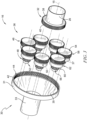
- the gearbox 16 includes a sun gear 32, a ring gear 34, and a plurality of compound gears 36.
- the sun gear 32 is coupled with the power shaft 26 and is driven in rotation about the axis 15 by the power shaft 26 during operation of the gas turbine engine 10.
- the ring gear 34 is coupled with each of the compound gears 36 and is driven in rotation by each of the compound gears 36 such that the compound gears interconnect the sun gear 32 and the ring gear 34.
- the ring gear 34 is also coupled with an output shaft 30 that drives the fan 14.
- the plurality of compound gears 36 are spaced circumferentially around the sun gear 32 and are driven in rotation by the sun gear 32.
- the plurality of compound gears 36 interconnect the sun gear 32 and the ring gear to transfer torque from the power shaft to the such that the plurality of compound gears 36 drive the output shaft 30 and the fan 14 in rotation about the axis 15.
- the power shaft 26 rotates at a common speed with the low-pressure turbine section 27.
- the gearbox 16 is configured to transfer increased torque from the power shaft 26 to the fan 14 through the output shaft 30 at a reduced rotational speed.
- the sun gear 32 is illustratively embodied as a helical gear and includes a gear body 38 and a plurality of gear teeth 40 extending outward from the gear body 38 as shown in Fig. 3 .
- the gear body 38 is coupled directly to the power shaft 26.
- the plurality of teeth 40 are spaced apart from the power shaft 26 and extend radially outward from the gear body 38 into engagement with each compound gear 36. In other embodiments, the plurality of teeth 40 may be formed directly onto the power shaft 26 such that the gear body 38 is omitted.
- the ring gear 34 is also embodied as a helical gear and includes a gear body 42 and a plurality of gear teeth 44 extending inwardly from the gear body 42 as shown in Fig. 3 .
- the gear body 42 is coupled to output shaft 30.
- the output shaft 30 includes a ring gear section 31 that has an increased diameter from a fan output section 33.
- a transition section 35 interconnects the ring gear section 31 with the fan output section 33.
- the output shaft 30 may have a constant diameter.
- the plurality of teeth 44 are spaced apart from the ring gear section 31 of the output shaft 30 and extend radially inward from the gear body 42 and into engagement with each of the compound gears 36.
- Each of the compound gears 36 includes a first-stage gear 46, a second-stage gear 48, a gear shaft 50, and a pinion 52 as shown in Fig. 3 .
- Each of the first-stage gears 46 and second-stage gears 48 are illustratively embodied as helical gears with respective gear bodies 54, 56 and gear teeth 58, 60 coupled to the gear bodies 54, 56.
- the first-stage gear 46 is aligned axially with the sun gear 32 when the gearbox 16 is fully assembled.
- the plurality of gear teeth 40 of the sun gear 32 mesh with the plurality of gear teeth 58 of each first-stage gear 46.
- Each of the second-stage gears 48 are positioned axially forward from the first-stage gears 46 and aligned axially with the ring gear 34.
- the plurality of gear teeth 44 of the ring gear 34 mesh with the plurality of gear teeth of each second-stage gear 48.
- the gear shaft 50 interconnects the first-stage gear 46 and the second-stage gear 48 such that the first-stage gear 46 and the second-stage gear rotate at a common angular speed.
- the pinion 52 is disposed in a cavity 51 that extends axially through the first-stage gear 46, the second-stage gear 48, and the gear shaft 50 and is configured to support each compound gear 36 for rotation about individual axes 37 that are fixed circumferentially around the axis 15.
- Each compound gear 36 may further include one or more bearings 62 to help support each compound gear 36 and to reduce friction between various rotating components such as, for example, the gear shaft 50 and/or the pinion 52.
- Each of the gears 32, 34, 36 included in the gearbox 16 is sized relative to one another to provide the rotational speed reduction described above and to minimize angular misalignments at interfaces between each gear where the gear teeth mesh with one another.
- Some gearboxes may include flexible (i.e. low stiffness) materials to account for angular misalignments so that loads are mitigated due to the angular misalignments.
- the gearbox 16 in the illustrative embodiment omits these flexible materials and addresses the angular misalignments by sizing each gear 32, 34, 36, as discussed below, so that they are less sensitive to angular misalignments at the interfaces between one another.
- the gearbox 16 in the illustrative embodiment is a compound star gearbox that uses a sun gear 32 with a larger diameter compared to sun gears included in other epicyclic gearboxes. Using planetary gears with two stages also allows for an increased diameter of the sun gear 32. Additionally, the compound star gearbox in the illustrative embodiment includes a relatively large number of planet gears 36. In the embodiment of the invention, the gearbox 16 includes seven compound gears 36 spaced circumferentially around the axis 15. Moreover, because the compound gears 36 are not rotating around axis 15, the compound gears 36 do not contribute any centrifugal forces. These aspects all contribute to decreasing a face width of each of the gears 32, 34, 36 which, in turn, minimizes gearbox sensitivity to angular misalignments.
- the sun gear 32 has a diameter 64 that is greater than a diameter 66 of each of the first-stage gears 46 and a diameter 68 of each of the second-stage gears 48 as shown in Fig. 4 .
- the ring gear 34 has a diameter 70 that is larger than diameters 64, 66, 68 to reduce the rotational speed of the power shaft 26 transferred to the output shaft 30 and the fan 14.
- the sun gear 32 in the illustrative embodiment has a larger diameter 64 than other gearboxes when compared to the diameter 70 of the ring gear 34.
- the diameter 64 of the sun gear 32 has a size that is relatively large in proportion to the diameter 70 of the ring gear 34.
- Tables 1A-1C contain values indicative of a ratio of the diameter 64 of the sun gear 32 to the diameter 70 of the ring gear 34 in terms of maximum limits and minimum limits for various gear ratios between 3 and 5.
- Table 1A displays these ratios for a gearbox with a total of seven compound gears 36 according to the invention.
- Table 1A Gear Ratio Min Ratio Limit Max Ratio Limit 3.0 0.42 0.58 3.5 0.44 0.57 4.0 0.46 0.55 4.5 0.47 0.53 5.0 0.48 0.51
- Table 1B displays these ratios for a gearbox with a total of five compound gears 36 according to examples not forming part of the invention.
- Table 1B Gear Ratio Min Ratio Limit Max Ratio Limit 3.0 0.23 0.57 3.5 0.25 0.55 4.0 0.27 0.54 4.5 0.28 0.52 5.0 0.30 0.51
- Table 1C displays these ratios for a gearbox with a total of three compound gears 36 according to examples not forming part of the invention.
- Table 1C Gear Ratio Min Ratio Limit Max Ratio Limit 3.0 0.24 0.55 3.5 0.25 0.56 4.0 0.25 0.53 4.5 0.26 0.52 5.0 0.28 0.50
- the sun gear and the ring gear have a gear ratio within a range of about 3 to about 5. In another embodiment, the sun gear 32 and the ring gear 34 have a gear ratio within a range of about 3 to about 4.5. In yet another embodiment, the sun gear 32 and the ring gear 34 have a gear ratio within a range of about 3.5 to about 4.
- the gearbox 16 includes seven, or more, compound gears and the ratio of the diameter 64 of the sun gear 32 to the diameter 70 of the ring gear 34 is within a range of about 0.2 to about 0.6. In another embodiment, the ratio of the diameter 64 of the sun gear 32 to the diameter 70 of the ring gear 34 is within a range of about 0.4 to about 0.6. In another embodiment, the ratio of the diameter 64 of the sun gear 32 to the diameter 70 of the ring gear 34 is within a range of about 0.46 to about 0.53. In another embodiment, the ratio of the diameter 64 of the sun gear 32 to the diameter 70 of the ring gear 34 is within a range of about 0.44 to about 0.55.
- the ratio of the diameter 64 of the sun gear 32 to the diameter 70 of the ring gear 34 is within a range of about 0.23 to about 0.57. In another embodiment, the ratio of the diameter 64 of the sun gear 32 to the diameter 70 of the ring gear 34 is within a range of about 0.25 to about 0.54. In another embodiment, the ratio of the diameter 64 of the sun gear 32 to the diameter 70 of the ring gear 34 is within a range of about 0.23 to about 0.53.
- a ratio of the diameter of the first-stage gear 46 to the diameter of the ring gear 34 is within a range of about 0.25 to about 0.4. In another embodiment, the ratio of the diameter of the first-stage gear 46 to the diameter of the ring gear 34 is within a range of about 0.29 to about 0.38. In another embodiment, the ratio of the diameter of the first-stage gear 46 to the diameter of the ring gear 34 is within a range of about 0.32 to about 0.36.
- a ratio of the diameter of the second-stage gear 48 to the diameter of the ring gear 34 is within a range of about 0.1 to about 0.3. In another embodiment, the ratio of the diameter of the second-stage gear 48 to the diameter of the ring gear 34 is within a range of about 0.13 to about 0.23. In another embodiment, the ratio of the diameter of the second-stage gear 48 to the diameter of the ring gear 34 is within a range of about 0.14 to about 0.19.
- a ratio of the diameter of the first-stage gear 46 to the diameter of the second-stage gear 48 is within a range of about 1 to about 3. In another embodiment, the ratio of the diameter of the first-stage gear 46 to the diameter of the second-stage gear 48 is within a range of about 1.5 to about 2.5. In another embodiment, the ratio of the diameter of the first-stage gear 46 to the diameter of the second-stage gear 48 is within a range of about 1.7 to about 2.1.
- the face widths of each of the first-stage gears 46 and the second-stage gears 48 may be minimized to reduce angular misalignments and, hence, loads on the gearbox 16.
- the first-stage gear 46 has a first face width 72 and the second-stage gear 48 has a second face width 74 as shown in Fig. 5 .
- the face widths 72, 74 may be normalized or compared with other features of the gas turbine engine 10 and/or the gearbox 16.
- the tables below contain ratios and values that are indicative of a gearbox 16 with compound gear face widths 72, 74 that reduce external angular misalignments.
- the values and ratios shown in the tables include: (i) face width numerical limits, (ii) face width-to-gear diameter (L/D), (iii) face width-to-fan power (mm/MW), (iv) face width-to-gearbox input torque (mm/kNm), (v) face width-to-stage input torque per planet (mm/kNm), (vi) face width-to-pinion gear diameter (mm/mm), (vii) face width-to-inverted tooth number (mm.tooth), (viii), and face width-to-fan diameter (mm/mm).
- Example 1 and Example 2 represent two non-limiting illustrative gearbox architectures that may be used in a small sized gas turbine engine, such as a gas turbine engine with a fan diameter of up to about 150 cm, a medium sized gas turbine engine, such as a gas turbine engine with a fan diameter within a range of about 150 cm to about 250 cm, and a large sized gas turbine engine, such as a gas turbine engine with a fan diameter of greater than about 250 cm.
- a small sized gas turbine engine such as a gas turbine engine with a fan diameter of up to about 150 cm
- a medium sized gas turbine engine such as a gas turbine engine with a fan diameter within a range of about 150 cm to about 250 cm
- a large sized gas turbine engine such as a gas turbine engine with a fan diameter of greater than about 250 cm.
- Tables 2 and 3 contain upper limits of values and/or ratios of the first-stage gear 46 and the second-stage gear, respectively, for the first example.
- Table 2 - Example 1 First-Stage Gear Upper Limits Value/Ratio Dimension Small Engine Medium Engine Large Engine Face width numerical limit mm 28.6 31.5 40 Face width-to-gear diameter (L/D) ratio mm/mm 0.118 0.095 0.101 Face width-to-fan power ratio mm/MW 1.40 1.14 0.71 Face width-to-gearbox input torque ratio mm/kNm 1.42 0.99 0.48 Face width-to-stage input torque per planet ratio mm/kNm 9.97 6.92 3.38 Face width-to-pinion gear diameter ratio mm/mm 0.17 0.16 0.14 Face width-to-inverted tooth number ratio mm.tooth 1544 2363 3560 Face width-to-fan diameter ratio mm/mm 0.0134 0.0119 0.0114 Table 3 - Example 1: Second-Stage Gear Upper Limits Value/Ratio Dimension Small Engine Medium Engine Large
- Tables 4 and 5 contain lower limits of values and/or ratios of the first-stage gear 46 and the second-stage gear 48, respectively, for the first example.
- Table 4 - Example 1 First-Stage Gear Lower Limits Value/Ratio Dimension Small Engine Medium Engine Large Engine Face width numerical limit mm 7.1 7.8 10 Face width-to-gear diameter (L/D) ratio mm/mm 0.029 0.023 0.025 Face width-to-fan power ratio mm/MW 0.35 0.28 0.18 Face width-to-gearbox input torque ratio mm/kNm 0.35 0.24 0.12 Face width-to-stage input torque per planet ratio mm/kNm 2.48 1.71 0.85 Face width-to-pinion gear diameter ratio mm/mm 0.04 0.04 0.03 Face width-to-inverted tooth number ratio mm.tooth 383 585 890 Face width-to-fan diameter ratio mm/mm 0.0033 0.0030 0.0029 Table 5 - Example 1: Second-Stage Gear Lower Limits Value/Ratio Dimension Small Engine Medium
- Tables 6 and 7 contain upper limits of values and/or ratios of the first-stage gear 46 and the second-stage gear 48, respectively, for the second example.
- Table 6 - Example 2 First-Stage Gear Upper Limits Value/Ratio Dimension Small Engine Medium Engine Large Engine Face width numerical limit mm 28.6 31.5 40 Face width-to-gear diameter (L/D) ratio mm/mm 0.099 0.109 0.089 Face width-to-fan power ratio mm/MW 1.40 1.14 0.71 Face width-to-gearbox input torque ratio mm/kNm 1.44 0.98 0.47 Face width-to-stage input torque per planet ratio mm/kNm 10.08 6.85 3.30 Face width-to-pinion gear diameter ratio mm/mm 0.20 0.15 0.15 Face width-to-inverted tooth number ratio mm.tooth 1859 2048 4080 Face width-to-fan diameter ratio mm/mm 0.0134 0.0119 0.0114 Table 7 - Example 2: Second-Stage Gear Upper Limits Value/Ratio Dimension Small Engine Medium
- Tables 8 and 9 contain lower limits of values and/or ratios of the first-stage gear 46 and the second-stage gear 48, respectively, for the second example.
- Table 8 - Example 2 First-Stage Gear Lower Limits Value/Ratio Dimension Small Engine Medium Engine Large Engine Face width numerical limit mm 7.1 7.8 10 Face width-to-gear diameter (L/D) ratio mm/mm 0.025 0.027 0.022 Face width-to-fan power ratio mm/MW 0.35 0.28 0.18 Face width-to-gearbox input torque ratio mm/kNm 0.36 0.24 0.12 Face width-to-stage input torque per planet ratio mm/kNm 2.50 1.70 0.83 Face width-to-pinion gear diameter ratio mm/mm 0.05 0.04 0.04 Face width-to-inverted tooth number ratio mm.tooth 462 507 1020 Face width-to-fan diameter ratio mm/mm 0.0033 0.0030 0.0029 Table 9 - Example 2: Second-Stage Gear Lower Limits Value/Ratio Dimension Small Engine Medium
- gearboxes with various values and/or ratios that minimize the face widths 72, 74 are described below.
- the first-stage gear 46 has a face width 72 of up to about 40 mm while the second-stage gear 48 has a face width 74 of up to about 55 mm. In another embodiment, the first-stage gear 46 has a face width 72 within a range of about 10 mm to about 40 mm while the second-stage gear 48 has a face width 74 within a range of about 15 mm to about 55 mm.
- the first-stage gear 46 has a face width-to-diameter ratio of up to about 0.12 while the second-stage gear 48 has a face width-to-diameter ratio of up to about 0.08.
- the first-stage gear has a face width-to-diameter ratio within a range of about 0.02 to about 0.12 while the second-stage gear 48 has a face width-to-diameter ratio of within a range of about 0.015 to about 0.08.
- the first-stage gear 46 has a face width-to-fan power ratio of up to about 0.8 mm/MW while the second-stage gear 48 has a face width-to-fan power ratio of up to about 1.1 mm/MW. In another embodiment, the first-stage gear 46 has a face width-to-fan power ratio of up to about 0.76 mm/MW while the second-stage gear 48 has a face width-to-fan power ratio of up to about 1.06 mm/MW.
- the first-stage gear 46 has a face width-to-gearbox input torque ratio of up to about 0.5 mm/kNm while the second-stage gear 48 has a face width-to-gearbox input torque ratio of up to about 1 mm/kNm. In another embodiment, the first-stage gear 46 has a face width-to-gearbox input torque ratio of up to about 0.51 mm/kNm while the second-stage gear 48 has a face width-to-gearbox input torque ratio of up to about 0.70 mm/kNm.
- the first-stage gear 46 has a face width-to-stage input torque ratio of up to about 0.5 mm/kNm while the second-stage gear 48 has a face width-to-stage input torque ratio of up to about 0.01 mm/kNm. In another embodiment, the first-stage gear 46 has a face width-to-stage input torque ratio of up to about 0.51 mm/kNm while the second-stage gear 48 has a face width-to-stage input torque ratio of up to about 0.0065 mm/kNm.
- the first-stage gear has a face width-to-pinion gear diameter ratio of up to about 0.2 and the second-stage gear has a face width-to-pinion gear diameter ratio of up to about 0.6.
- the first-stage gear has a face width-to-inverted tooth number ratio of up to about 4100 and the second-stage gear has a face width-to-inverted tooth number ratio of up to about 10,500.
- the first stage gear has a face width-to-fan diameter ratio of up to about 0.014 and the second-stage gear has a face width-to-fan diameter ratio of up to about 0.02.
- the first-stage gear has a face width-to-fan diameter ratio within a range of about 0.002 to about 0.014 and the second-stage gear has a face width-to-fan diameter ratio within a range of about 0.004 to about 0.02.
- the present invention relates to a gas turbine engine.
- a gas turbine engine comprises an engine core comprising a turbine, a combustor, a compressor, and a core shaft connecting the turbine to the compressor.
- a gas turbine engine comprises a fan (having fan blades) located upstream of the engine core.
- the gas turbine engine comprises a gearbox that receives an input from the core shaft and outputs drive to the fan so as to drive the fan at a lower rotational speed than the core shaft.
- the input to the gearbox may be directly from the core shaft, or indirectly from the core shaft, for example via a spur shaft and/or gear.
- the core shaft may rigidly connect the turbine and the compressor, such that the turbine and compressor rotate at the same speed (with the fan rotating at a lower speed).
- the gearbox may be a reduction gearbox (in that the output to the fan is a lower rotational rate than the input from the core shaft).
- the gearbox may be a "planetary” or “star” gearbox, as described in more detail elsewhere herein.
- the gearbox may have any desired reduction ratio (defined as the rotational speed of the input shaft divided by the rotational speed of the output shaft), for example greater than 2.5, for example in the range of from 3 to 4.2, or 3.2 to 3.8, for example on the order of or at least 3, 3.1, 3.2, 3.3, 3.4, 3.5, 3.6, 3.7, 3.8, 3.9, 4, 4.1,4.2, 4.3, 4.4, 4.5, 4.6, 4.7, 4.8, 4.9, or 5.
- the gear ratio may be, for example, between any two of the values in the previous sentence.
- the gearbox may be a "star” gearbox having one of the gear ratios described above. In some arrangements, the gear ratio may be outside these ranges.
- the radius of the fan may be measured between the engine centerline and the tip of a fan blade at its leading edge.
- the fan diameter (which may simply be twice the radius of the fan) may be greater than (or on the order of) any of: 220 cm, 230 cm, 240 cm, 250 cm (around 100 inches), 260 cm, 270 cm (around 105 inches), 280 cm (around 110 inches), 290 cm (around 115 inches), 300 cm (around 120 inches), 310 cm, 320 cm (around 125 inches), 330 cm (around 130 inches), 340 cm (around 135 inches), 350cm, 360cm (around 140 inches), 370 cm (around 145 inches), 380 (around 150 inches) cm, 390 cm (around 155 inches), 400 cm, 410 cm (around 160 inches), 420 cm (around 165 inches), or greater than 420 cm.
- the fan diameter may be in an inclusive range bounded by any two of the values in the previous sentence (i.e. the values may form upper or lower bounds), for example in the range of from about 240 cm to about 280 cm or about 330 cm to about 380 cm.
- the rotational speed of the fan may vary in use. Generally, the rotational speed is lower for fans with a higher diameter. Purely by way of non-limitative example, the rotational speed of the fan at cruise conditions may be less than about 2500 rpm, for example less than about 2300 rpm. Purely by way of further non-limitative example, the rotational speed of the fan at cruise conditions for an engine having a fan diameter in the range of from 220 cm to 300 cm (for example 240 cm to 280 cm or 250 cm to 270cm) may be in the range of from 1700 rpm to 2500 rpm, for example in the range of from 1800 rpm to 2300 rpm, for example in the range of from 1900 rpm to 2100 rpm.
- the rotational speed of the fan at cruise conditions for an engine having a fan diameter in the range of from 330 cm to 380 cm may be in the range of from 1200 rpm to 2000 rpm, for example in the range of from 1300 rpm to 1800 rpm, for example in the range of from 1400 rpm to 1800 rpm.
- a gas turbine engine as described and/or claimed herein may have any desired maximum thrust.
- a gas turbine as described and/or claimed herein may be capable of producing a maximum thrust of at least (or on the order of) any of the following: 160kN, 170kN, 180kN, 190kN, 200kN, 250kN, 300kN, 350kN, 400kN, 450kN, 500kN, or 550kN.
- the maximum thrust may be in an inclusive range bounded by any two of the values in the previous sentence (i.e. the values may form upper or lower bounds).
- a gas turbine as described and/or claimed herein may be capable of producing a maximum thrust in the range of from 330kN to 420 kN, for example 350kN to 400kN.
- the thrust referred to above may be the maximum net thrust at standard atmospheric conditions at sea level plus 15 degrees C (ambient pressure 101.3kPa, temperature 30 degrees C), with the engine static.
- angular mis-alignments within gearboxes may contribute to an increase in loading in both the gears and bearing components.
- Some gas turbine engines may introduce lateral and angular flexibility (low stiffness) into various parts of the gearbox to compensate for this issue.
- the present invention may change the configuration of the gearbox away from the single stage designs, and use low face width gears which are better at operating with or minimizing angular mis-alignments.
- the present invention uses a compound epicyclic gearbox which achieves the overall gear ratio desired using two stages. This allows the inclusion of larger diameter gears, and hence, much smaller face widths.
- a gas turbine engine for an aircraft includes: an engine core comprising a turbine, a compressor, and a core shaft connecting the turbine to the compressor; a fan located upstream of the engine core, the fan comprising a plurality of fan blades; a gearbox that receives an input from the core shaft and outputs drive to the fan so as to drive the fan at a lower rotational speed than the core shaft; and wherein the gearbox is a compound epicyclic gearbox the gearbox having two stages, the first stage having a tooth face width in the range of the face width numerical limits shown in Tables 4 and/or 8 to the face width numerical limits shown in Tables 2 and/or 6, the second stage having a tooth face width in the range of the face width numerical limits shown in Tables 5 and/or 9 to the face width numerical limits shown in Tables 3 and/or 7.
- mis-alignment is an angular quantity generally expressed in milli-radians which is equivalent to thou per inch.
- the total range of gear teeth movement may be this angular misalignment multiplied by the face width.
- Narrower face widths are sometimes less sensitive to misalignment.
- face widths are less for a Double Helical DP1A comparable gearbox (GBX) diameter of about 800 mm.
- the input central sun gear is a much larger proportion of the output ring gear than other gearboxes.
- there is a high number of planet gears at least seven.
- the planet gear teeth which mesh with the sun gear are distinct from those which mesh with the ring gear.
- the planet gears do not orbit around the engine centerline, and hence do not create centrifugal loads. These four aspects may allow a larger sun gear size and hence a lower gear face width.
- higher gearbox diameters are enabled by using the compound star configuration giving no rotational contribution to the bearing load and face widths can be dropped to about 40 mm.
- compound gearboxes may be able to cope with externally (engine in this case) generated mis-alignments without having a commonly used flexible member (either input shaft, ring gear, or carrier mounting).
- an upper limit of each face width is around about 33% of other comparative designs.
- a comparative gearbox may have a face width of around about 100 mm, about 120 mm, and about 150 mm at small, medium, and large engine sizes.
- lower limits may be based on the ultimate capacity of the gear teeth of each gear - this may be around about 25% of the upper limit. In other words, this may be the largest load that can be transmitted by any gear even assuming perfect alignment conditions.
Landscapes
- Engineering & Computer Science (AREA)
- General Engineering & Computer Science (AREA)
- Mechanical Engineering (AREA)
- Chemical & Material Sciences (AREA)
- Combustion & Propulsion (AREA)
- Retarders (AREA)
Claims (15)
- Gasturbinentriebwerk (10), umfassend:einen Triebwerkskern (12), beinhaltend einen Verdichter (20), eine Brennkammer (22) und eine Turbine (24), die entlang einer Referenzachse (15) angeordnet ist, wobei die Turbine (24) konfiguriert ist, um Drehung einer Antriebswelle (26) um die Referenzachse (15) während Betrieb des Gasturbinentriebwerks (10) anzutreiben,ein Gebläse (14), das durch eine Abtriebswelle (30) in Drehung um die Referenzachse (15) angetrieben wird, undein Getriebe (16), das die Abtriebswelle (30) und die Antriebswelle (26) miteinander verbindet, um Drehenergie von der Turbine (24) auf das Gebläse (14) während Betrieb des Gasturbinentriebwerks (10) zu übertragen, wobei das Getriebe (16) (i) ein Sonnenrad (32), das mit der Antriebswelle (26) für Drehung um die Referenzachse (15) mit der Antriebswelle (26) gekoppelt ist, (ii) eine Vielzahl von Verbundrädern (36), die mit dem Sonnenrad (32) gekoppelt und umlaufend um die Referenzachse (15) voneinander beabstandet ist, wobei jedes Verbundrad (36) in Drehung durch das Sonnenrad (32) um eine Verbundradachse (37) angetrieben wird, die relativ zu der Referenzachse (15) in Position fixiert ist, und (iii) ein Hohlrad (34), das mit jedem der Verbundräder (36) und der Abtriebswelle (30) gekoppelt ist, um die Drehenergie von der Vielzahl von Verbundrädern (36) an die Abtriebswelle (30) zu übertragen, um Drehung des Gebläses (14) anzutreiben, beinhaltet,wobei jedes Verbundrad (36) ein Rad der ersten Stufe (46), das mit dem Sonnenrad (32) gekoppelt ist, ein Rad der zweiten Stufe (48), das axial von dem Rad der ersten Stufe (46) beabstandet und mit dem Hohlrad (34) gekoppelt ist, und eine Verbundgetriebewelle (50), die das Rad der ersten Stufe (46) und das Rad der zweiten Stufe (48) miteinander verbindet, um zu bewirken, dass sich das Rad der ersten Stufe (46) und das Rad der zweiten Stufe (48) gemeinsam drehen, beinhaltet, wobei das Rad der ersten Stufe (46) und die Räder der zweiten Stufe (48) Durchmesser (66, 68) aufweisen, die kleiner als ein Durchmesser (64) des Sonnenrads (32) sind;dadurch gekennzeichnet, dassdas Getriebe (16) sieben oder mehr Verbundräder beinhaltet und das Verhältnis des Durchmessers (64) des Sonnenrads (32) zu dem Durchmesser (70) des Hohlrads (34) innerhalb eines Bereichs von 0,2 bis 0,6 ist.
- Gasturbinentriebwerk (10) nach Anspruch 1, wobei das Rad der ersten Stufe (46) eine Flächenbreite (72) von bis zu 40 mm aufweist.
- Gasturbinentriebwerk (10) nach Anspruch 1, wobei das Rad der ersten Stufe (46) eine Flächenbreite (72) innerhalb eines Bereichs von 10 mm bis 40 mm aufweist.
- Gasturbinentriebwerk (10) nach einem der Ansprüche 1 bis 3, wobei die Vielzahl von Verbundrädern (36) eine ungerade Anzahl an Verbundrädern (36) beinhaltet.
- Gasturbinentriebwerk (10) nach einem der Ansprüche 1 bis 4, wobei das Rad der ersten Stufe (46) ein Verhältnis von Flächenbreite zu Durchmesser von bis zu 0,12 aufweist.
- Gasturbinentriebwerk (10) nach einem der Ansprüche 1 bis 4, wobei das Rad der ersten Stufe (46) ein Verhältnis von Flächenbreite zu Durchmesser innerhalb eines Bereichs von 0,02 bis 0,12 aufweist.
- Gasturbinentriebwerk (10) nach einem der Ansprüche 1 bis 6, wobei das Rad der ersten Stufe (46) ein Verhältnis von Flächenbreite zu Gebläseleistung von bis zu 0,8 mm/MW aufweist.
- Gasturbinentriebwerk (10) nach einem der Ansprüche 1 bis 7, wobei das Rad der ersten Stufe (46) ein Verhältnis von Flächenbreite zu Getriebeeingangsdrehmoment von bis zu 0,5 mm/kNm aufweist.
- Gasturbinentriebwerk (10) nach einem der Ansprüche 1 bis 8, wobei das Rad der ersten Stufe (46) ein Verhältnis von Flächenbreite zu Ritzeldurchmesser von bis zu 0,2 aufweist.
- Gasturbinentriebwerk (10) nach einem der Ansprüche 1 bis 9, wobei das Rad der ersten Stufe (46) ein Verhältnis von Flächenbreite zu Gebläsedurchmesser von bis zu 0,014 aufweist.
- Gasturbinentriebwerk (10) nach einem der Ansprüche 1 bis 9, wobei das Rad der ersten Stufe (46) ein Verhältnis von Flächenbreite zu Gebläsedurchmesser innerhalb eines Bereichs von 0,002 bis 0,014 aufweist.
- Gasturbinentriebwerk (10) nach einem der Ansprüche 1 bis 11, wobei das Rad der zweiten Stufe (48) eine Flächenbreite (74) von bis zu 55 mm aufweist.
- Gasturbinentriebwerk (10) nach einem der Ansprüche 1 bis 11, wobei das Rad der zweiten Stufe (48) eine Flächenbreite (74) innerhalb eines Bereichs von 15 mm bis 55 mm aufweist.
- Gasturbinentriebwerk (10) nach einem der Ansprüche 1 bis 13, wobei das Rad der zweiten Stufe (48) ein Verhältnis von Flächenbreite zu Durchmesser von bis zu 0,08 aufweist.
- Gasturbinentriebwerk (10) nach einem der Ansprüche 1 bis 13, wobei das Rad der zweiten Stufe (48) ein Verhältnis von Flächenbreite zu Durchmesser innerhalb eines Bereichs von 0,015 bis 0,08 aufweist.
Applications Claiming Priority (1)
| Application Number | Priority Date | Filing Date | Title |
|---|---|---|---|
| US16/515,730 US11274729B2 (en) | 2019-07-18 | 2019-07-18 | Turbofan gas turbine engine with gearbox |
Publications (2)
| Publication Number | Publication Date |
|---|---|
| EP3767100A1 EP3767100A1 (de) | 2021-01-20 |
| EP3767100B1 true EP3767100B1 (de) | 2023-10-11 |
Family
ID=71108440
Family Applications (1)
| Application Number | Title | Priority Date | Filing Date |
|---|---|---|---|
| EP20180729.4A Active EP3767100B1 (de) | 2019-07-18 | 2020-06-18 | Mantelstromtriebwerk mit getriebe |
Country Status (3)
| Country | Link |
|---|---|
| US (1) | US11274729B2 (de) |
| EP (1) | EP3767100B1 (de) |
| CN (1) | CN112240246B (de) |
Families Citing this family (12)
| Publication number | Priority date | Publication date | Assignee | Title |
|---|---|---|---|---|
| US12060837B2 (en) | 2017-02-10 | 2024-08-13 | Pratt & Whitney Canada Corp. | Reduction gearbox for gas turbine engine |
| US11313438B2 (en) * | 2019-07-18 | 2022-04-26 | Rolls-Royce Plc | Turbofan gas turbine engine with gearbox |
| US11643972B2 (en) * | 2020-06-15 | 2023-05-09 | Ge Avio S.R.L. | Turbomachines and epicyclic gear assemblies with symmetrical compound arrangement |
| IT202100015386A1 (it) * | 2021-06-11 | 2022-12-11 | Ge Avio Srl | Turbomacchine e gruppi ad ingranaggi epicicloidali con canali di lubrificazione |
| EP4148263A1 (de) * | 2021-09-08 | 2023-03-15 | Rolls-Royce plc | Verbessertes gasturbinentriebwerk |
| EP4148250B1 (de) | 2021-09-08 | 2025-08-06 | Rolls-Royce plc | Verbesserter gasturbinenmotor |
| US12320418B2 (en) * | 2022-06-22 | 2025-06-03 | General Electric Company | Gearbox assembly with lubricant extraction volume ratio |
| US12421898B2 (en) | 2022-06-22 | 2025-09-23 | General Electric Company | Gearbox assembly with lubricant extraction volume ratio |
| US12523176B2 (en) | 2022-06-22 | 2026-01-13 | General Electric Company | Gearbox assembly with lubricant extraction volume ratio |
| US12345201B2 (en) | 2022-06-22 | 2025-07-01 | General Electric Company | Gearbox assembly with lubricant extraction volume ratio |
| US12326115B2 (en) * | 2022-06-22 | 2025-06-10 | General Electric Company | Gearbox assembly with lubricant extraction volume ratio |
| GB202319125D0 (en) | 2023-12-14 | 2024-01-31 | Rolls Royce Plc | Operating a gas turbine engine |
Family Cites Families (15)
| Publication number | Priority date | Publication date | Assignee | Title |
|---|---|---|---|---|
| US4699021A (en) * | 1984-09-20 | 1987-10-13 | Avco Corporation | Integrated power system |
| US4815273A (en) * | 1985-12-31 | 1989-03-28 | Peter Rudolph | Single propeller turboprop propulsion apparatus |
| US7752836B2 (en) | 2005-10-19 | 2010-07-13 | General Electric Company | Gas turbine assembly and methods of assembling same |
| US7704178B2 (en) * | 2006-07-05 | 2010-04-27 | United Technologies Corporation | Oil baffle for gas turbine fan drive gear system |
| US8807916B2 (en) * | 2012-09-27 | 2014-08-19 | United Technologies Corporation | Method for setting a gear ratio of a fan drive gear system of a gas turbine engine |
| US8753065B2 (en) * | 2012-09-27 | 2014-06-17 | United Technologies Corporation | Method for setting a gear ratio of a fan drive gear system of a gas turbine engine |
| US8678743B1 (en) * | 2013-02-04 | 2014-03-25 | United Technologies Corporation | Method for setting a gear ratio of a fan drive gear system of a gas turbine engine |
| JP6628518B2 (ja) * | 2015-07-31 | 2020-01-08 | 川崎重工業株式会社 | 歯車の冷却構造 |
| US20180080411A1 (en) | 2016-09-16 | 2018-03-22 | General Electric Company | Gas turbine engine |
| US10113482B2 (en) * | 2016-11-15 | 2018-10-30 | Pratt & Whitney Canada Corp. | Gearbox for gas turbine engine |
| FR3066004B1 (fr) * | 2017-05-04 | 2020-09-11 | Safran Trans Systems | Reducteur de vitesse debrayable |
| GB201712993D0 (en) * | 2017-08-14 | 2017-09-27 | Rolls Royce Plc | Gas turbine engine |
| FR3071025B1 (fr) * | 2017-09-12 | 2021-02-12 | Safran Trans Systems | Pivot pour palier lisse et train d'engrenages a contraintes thermiques reduites |
| US10801443B2 (en) * | 2018-10-05 | 2020-10-13 | Raytheon Technologies Corporation | Fan drive gear system electrical conditioning circuit for hybrid electric gas turbine engine |
| US11313438B2 (en) * | 2019-07-18 | 2022-04-26 | Rolls-Royce Plc | Turbofan gas turbine engine with gearbox |
-
2019
- 2019-07-18 US US16/515,730 patent/US11274729B2/en active Active
-
2020
- 2020-05-07 CN CN202010375636.XA patent/CN112240246B/zh active Active
- 2020-06-18 EP EP20180729.4A patent/EP3767100B1/de active Active
Also Published As
| Publication number | Publication date |
|---|---|
| CN112240246B (zh) | 2024-07-12 |
| CN112240246A (zh) | 2021-01-19 |
| EP3767100A1 (de) | 2021-01-20 |
| US20210017910A1 (en) | 2021-01-21 |
| US11274729B2 (en) | 2022-03-15 |
Similar Documents
| Publication | Publication Date | Title |
|---|---|---|
| EP3767131A1 (de) | Mantelstromtriebwerkgasturbinenmotor mit getriebe | |
| EP3767100A1 (de) | Mantelstromtriebwerkgasturbinenmotor mit getriebe | |
| US11377199B2 (en) | Planetary gearbox for gas turbine engine | |
| US5274999A (en) | Turbofan engine having a contrarotating low-pressure compressor | |
| EP2360391B1 (de) | Epizyklisches Getriebe | |
| EP2199568B1 (de) | Gegenläufige Differenzdrehzahl-Niederdruckturbine mit Getriebe | |
| EP1777406B1 (de) | Turbofan-Triebwerk mit gegenläufigen Fans | |
| US6082967A (en) | Constant-speed twin spool turboprop unit | |
| US7841165B2 (en) | Gas turbine engine assembly and methods of assembling same | |
| EP4283106B1 (de) | Selektive leistungsverteilung für ein flugzeugantriebssystem | |
| US4118997A (en) | Bevel gearing | |
| US8075438B2 (en) | Apparatus and method for transmitting a rotary input into counter-rotating outputs | |
| US11555454B2 (en) | Triple flow aircraft turbomachine provided with a power transmission module | |
| US10502144B2 (en) | Gas turbine engine with a geared turbofan arrangement | |
| CN112610337B (zh) | 用于周转齿轮系统外壳组件的加强构件 | |
| US10408134B2 (en) | Gears, gear arrangements and gas turbine engines | |
| GB2575046A (en) | Gas turbine engine spool | |
| US2739490A (en) | Transmission mechanism, including bevel pinions | |
| US3091382A (en) | Gas turbine engines | |
| EP4283105A1 (de) | Flugzeugantriebssystem mit drehzahlvariabler drehstruktur |
Legal Events
| Date | Code | Title | Description |
|---|---|---|---|
| PUAI | Public reference made under article 153(3) epc to a published international application that has entered the european phase |
Free format text: ORIGINAL CODE: 0009012 |
|
| STAA | Information on the status of an ep patent application or granted ep patent |
Free format text: STATUS: THE APPLICATION HAS BEEN PUBLISHED |
|
| AK | Designated contracting states |
Kind code of ref document: A1 Designated state(s): AL AT BE BG CH CY CZ DE DK EE ES FI FR GB GR HR HU IE IS IT LI LT LU LV MC MK MT NL NO PL PT RO RS SE SI SK SM TR |
|
| AX | Request for extension of the european patent |
Extension state: BA ME |
|
| STAA | Information on the status of an ep patent application or granted ep patent |
Free format text: STATUS: REQUEST FOR EXAMINATION WAS MADE |
|
| 17P | Request for examination filed |
Effective date: 20210719 |
|
| RBV | Designated contracting states (corrected) |
Designated state(s): AL AT BE BG CH CY CZ DE DK EE ES FI FR GB GR HR HU IE IS IT LI LT LU LV MC MK MT NL NO PL PT RO RS SE SI SK SM TR |
|
| GRAP | Despatch of communication of intention to grant a patent |
Free format text: ORIGINAL CODE: EPIDOSNIGR1 |
|
| STAA | Information on the status of an ep patent application or granted ep patent |
Free format text: STATUS: GRANT OF PATENT IS INTENDED |
|
| RIC1 | Information provided on ipc code assigned before grant |
Ipc: F16H 1/32 20060101ALI20230614BHEP Ipc: F16H 1/28 20060101ALI20230614BHEP Ipc: F02K 3/06 20060101AFI20230614BHEP |
|
| INTG | Intention to grant announced |
Effective date: 20230714 |
|
| GRAS | Grant fee paid |
Free format text: ORIGINAL CODE: EPIDOSNIGR3 |
|
| GRAA | (expected) grant |
Free format text: ORIGINAL CODE: 0009210 |
|
| STAA | Information on the status of an ep patent application or granted ep patent |
Free format text: STATUS: THE PATENT HAS BEEN GRANTED |
|
| P01 | Opt-out of the competence of the unified patent court (upc) registered |
Effective date: 20230818 |
|
| AK | Designated contracting states |
Kind code of ref document: B1 Designated state(s): AL AT BE BG CH CY CZ DE DK EE ES FI FR GB GR HR HU IE IS IT LI LT LU LV MC MK MT NL NO PL PT RO RS SE SI SK SM TR |
|
| REG | Reference to a national code |
Ref country code: GB Ref legal event code: FG4D |
|
| REG | Reference to a national code |
Ref country code: CH Ref legal event code: EP |
|
| REG | Reference to a national code |
Ref country code: DE Ref legal event code: R096 Ref document number: 602020018910 Country of ref document: DE |
|
| REG | Reference to a national code |
Ref country code: IE Ref legal event code: FG4D |
|
| REG | Reference to a national code |
Ref country code: LT Ref legal event code: MG9D |
|
| REG | Reference to a national code |
Ref country code: NL Ref legal event code: MP Effective date: 20231011 |
|
| REG | Reference to a national code |
Ref country code: AT Ref legal event code: MK05 Ref document number: 1620438 Country of ref document: AT Kind code of ref document: T Effective date: 20231011 |
|
| PG25 | Lapsed in a contracting state [announced via postgrant information from national office to epo] |
Ref country code: NL Free format text: LAPSE BECAUSE OF FAILURE TO SUBMIT A TRANSLATION OF THE DESCRIPTION OR TO PAY THE FEE WITHIN THE PRESCRIBED TIME-LIMIT Effective date: 20231011 |
|
| PG25 | Lapsed in a contracting state [announced via postgrant information from national office to epo] |
Ref country code: GR Free format text: LAPSE BECAUSE OF FAILURE TO SUBMIT A TRANSLATION OF THE DESCRIPTION OR TO PAY THE FEE WITHIN THE PRESCRIBED TIME-LIMIT Effective date: 20240112 |
|
| PG25 | Lapsed in a contracting state [announced via postgrant information from national office to epo] |
Ref country code: IS Free format text: LAPSE BECAUSE OF FAILURE TO SUBMIT A TRANSLATION OF THE DESCRIPTION OR TO PAY THE FEE WITHIN THE PRESCRIBED TIME-LIMIT Effective date: 20240211 |
|
| PG25 | Lapsed in a contracting state [announced via postgrant information from national office to epo] |
Ref country code: LT Free format text: LAPSE BECAUSE OF FAILURE TO SUBMIT A TRANSLATION OF THE DESCRIPTION OR TO PAY THE FEE WITHIN THE PRESCRIBED TIME-LIMIT Effective date: 20231011 |
|
| PG25 | Lapsed in a contracting state [announced via postgrant information from national office to epo] |
Ref country code: AT Free format text: LAPSE BECAUSE OF FAILURE TO SUBMIT A TRANSLATION OF THE DESCRIPTION OR TO PAY THE FEE WITHIN THE PRESCRIBED TIME-LIMIT Effective date: 20231011 |
|
| PG25 | Lapsed in a contracting state [announced via postgrant information from national office to epo] |
Ref country code: ES Free format text: LAPSE BECAUSE OF FAILURE TO SUBMIT A TRANSLATION OF THE DESCRIPTION OR TO PAY THE FEE WITHIN THE PRESCRIBED TIME-LIMIT Effective date: 20231011 |
|
| PG25 | Lapsed in a contracting state [announced via postgrant information from national office to epo] |
Ref country code: LT Free format text: LAPSE BECAUSE OF FAILURE TO SUBMIT A TRANSLATION OF THE DESCRIPTION OR TO PAY THE FEE WITHIN THE PRESCRIBED TIME-LIMIT Effective date: 20231011 Ref country code: IS Free format text: LAPSE BECAUSE OF FAILURE TO SUBMIT A TRANSLATION OF THE DESCRIPTION OR TO PAY THE FEE WITHIN THE PRESCRIBED TIME-LIMIT Effective date: 20240211 Ref country code: GR Free format text: LAPSE BECAUSE OF FAILURE TO SUBMIT A TRANSLATION OF THE DESCRIPTION OR TO PAY THE FEE WITHIN THE PRESCRIBED TIME-LIMIT Effective date: 20240112 Ref country code: ES Free format text: LAPSE BECAUSE OF FAILURE TO SUBMIT A TRANSLATION OF THE DESCRIPTION OR TO PAY THE FEE WITHIN THE PRESCRIBED TIME-LIMIT Effective date: 20231011 Ref country code: BG Free format text: LAPSE BECAUSE OF FAILURE TO SUBMIT A TRANSLATION OF THE DESCRIPTION OR TO PAY THE FEE WITHIN THE PRESCRIBED TIME-LIMIT Effective date: 20240111 Ref country code: AT Free format text: LAPSE BECAUSE OF FAILURE TO SUBMIT A TRANSLATION OF THE DESCRIPTION OR TO PAY THE FEE WITHIN THE PRESCRIBED TIME-LIMIT Effective date: 20231011 Ref country code: PT Free format text: LAPSE BECAUSE OF FAILURE TO SUBMIT A TRANSLATION OF THE DESCRIPTION OR TO PAY THE FEE WITHIN THE PRESCRIBED TIME-LIMIT Effective date: 20240212 |
|
| PG25 | Lapsed in a contracting state [announced via postgrant information from national office to epo] |
Ref country code: SE Free format text: LAPSE BECAUSE OF FAILURE TO SUBMIT A TRANSLATION OF THE DESCRIPTION OR TO PAY THE FEE WITHIN THE PRESCRIBED TIME-LIMIT Effective date: 20231011 Ref country code: RS Free format text: LAPSE BECAUSE OF FAILURE TO SUBMIT A TRANSLATION OF THE DESCRIPTION OR TO PAY THE FEE WITHIN THE PRESCRIBED TIME-LIMIT Effective date: 20231011 Ref country code: PL Free format text: LAPSE BECAUSE OF FAILURE TO SUBMIT A TRANSLATION OF THE DESCRIPTION OR TO PAY THE FEE WITHIN THE PRESCRIBED TIME-LIMIT Effective date: 20231011 Ref country code: NO Free format text: LAPSE BECAUSE OF FAILURE TO SUBMIT A TRANSLATION OF THE DESCRIPTION OR TO PAY THE FEE WITHIN THE PRESCRIBED TIME-LIMIT Effective date: 20240111 Ref country code: LV Free format text: LAPSE BECAUSE OF FAILURE TO SUBMIT A TRANSLATION OF THE DESCRIPTION OR TO PAY THE FEE WITHIN THE PRESCRIBED TIME-LIMIT Effective date: 20231011 Ref country code: HR Free format text: LAPSE BECAUSE OF FAILURE TO SUBMIT A TRANSLATION OF THE DESCRIPTION OR TO PAY THE FEE WITHIN THE PRESCRIBED TIME-LIMIT Effective date: 20231011 |
|
| PG25 | Lapsed in a contracting state [announced via postgrant information from national office to epo] |
Ref country code: DK Free format text: LAPSE BECAUSE OF FAILURE TO SUBMIT A TRANSLATION OF THE DESCRIPTION OR TO PAY THE FEE WITHIN THE PRESCRIBED TIME-LIMIT Effective date: 20231011 |
|
| REG | Reference to a national code |
Ref country code: DE Ref legal event code: R097 Ref document number: 602020018910 Country of ref document: DE |
|
| PG25 | Lapsed in a contracting state [announced via postgrant information from national office to epo] |
Ref country code: CZ Free format text: LAPSE BECAUSE OF FAILURE TO SUBMIT A TRANSLATION OF THE DESCRIPTION OR TO PAY THE FEE WITHIN THE PRESCRIBED TIME-LIMIT Effective date: 20231011 |
|
| PG25 | Lapsed in a contracting state [announced via postgrant information from national office to epo] |
Ref country code: SK Free format text: LAPSE BECAUSE OF FAILURE TO SUBMIT A TRANSLATION OF THE DESCRIPTION OR TO PAY THE FEE WITHIN THE PRESCRIBED TIME-LIMIT Effective date: 20231011 |
|
| PG25 | Lapsed in a contracting state [announced via postgrant information from national office to epo] |
Ref country code: SM Free format text: LAPSE BECAUSE OF FAILURE TO SUBMIT A TRANSLATION OF THE DESCRIPTION OR TO PAY THE FEE WITHIN THE PRESCRIBED TIME-LIMIT Effective date: 20231011 Ref country code: SK Free format text: LAPSE BECAUSE OF FAILURE TO SUBMIT A TRANSLATION OF THE DESCRIPTION OR TO PAY THE FEE WITHIN THE PRESCRIBED TIME-LIMIT Effective date: 20231011 Ref country code: RO Free format text: LAPSE BECAUSE OF FAILURE TO SUBMIT A TRANSLATION OF THE DESCRIPTION OR TO PAY THE FEE WITHIN THE PRESCRIBED TIME-LIMIT Effective date: 20231011 Ref country code: IT Free format text: LAPSE BECAUSE OF FAILURE TO SUBMIT A TRANSLATION OF THE DESCRIPTION OR TO PAY THE FEE WITHIN THE PRESCRIBED TIME-LIMIT Effective date: 20231011 Ref country code: EE Free format text: LAPSE BECAUSE OF FAILURE TO SUBMIT A TRANSLATION OF THE DESCRIPTION OR TO PAY THE FEE WITHIN THE PRESCRIBED TIME-LIMIT Effective date: 20231011 Ref country code: DK Free format text: LAPSE BECAUSE OF FAILURE TO SUBMIT A TRANSLATION OF THE DESCRIPTION OR TO PAY THE FEE WITHIN THE PRESCRIBED TIME-LIMIT Effective date: 20231011 Ref country code: CZ Free format text: LAPSE BECAUSE OF FAILURE TO SUBMIT A TRANSLATION OF THE DESCRIPTION OR TO PAY THE FEE WITHIN THE PRESCRIBED TIME-LIMIT Effective date: 20231011 |
|
| PLBE | No opposition filed within time limit |
Free format text: ORIGINAL CODE: 0009261 |
|
| STAA | Information on the status of an ep patent application or granted ep patent |
Free format text: STATUS: NO OPPOSITION FILED WITHIN TIME LIMIT |
|
| 26N | No opposition filed |
Effective date: 20240712 |
|
| PG25 | Lapsed in a contracting state [announced via postgrant information from national office to epo] |
Ref country code: SI Free format text: LAPSE BECAUSE OF FAILURE TO SUBMIT A TRANSLATION OF THE DESCRIPTION OR TO PAY THE FEE WITHIN THE PRESCRIBED TIME-LIMIT Effective date: 20231011 |
|
| PG25 | Lapsed in a contracting state [announced via postgrant information from national office to epo] |
Ref country code: SI Free format text: LAPSE BECAUSE OF FAILURE TO SUBMIT A TRANSLATION OF THE DESCRIPTION OR TO PAY THE FEE WITHIN THE PRESCRIBED TIME-LIMIT Effective date: 20231011 |
|
| PG25 | Lapsed in a contracting state [announced via postgrant information from national office to epo] |
Ref country code: MC Free format text: LAPSE BECAUSE OF FAILURE TO SUBMIT A TRANSLATION OF THE DESCRIPTION OR TO PAY THE FEE WITHIN THE PRESCRIBED TIME-LIMIT Effective date: 20231011 |
|
| REG | Reference to a national code |
Ref country code: CH Ref legal event code: PL |
|
| PG25 | Lapsed in a contracting state [announced via postgrant information from national office to epo] |
Ref country code: LU Free format text: LAPSE BECAUSE OF NON-PAYMENT OF DUE FEES Effective date: 20240618 |
|
| PG25 | Lapsed in a contracting state [announced via postgrant information from national office to epo] |
Ref country code: IE Free format text: LAPSE BECAUSE OF NON-PAYMENT OF DUE FEES Effective date: 20240618 |
|
| PG25 | Lapsed in a contracting state [announced via postgrant information from national office to epo] |
Ref country code: CH Free format text: LAPSE BECAUSE OF NON-PAYMENT OF DUE FEES Effective date: 20240630 Ref country code: BE Free format text: LAPSE BECAUSE OF NON-PAYMENT OF DUE FEES Effective date: 20240630 |
|
| REG | Reference to a national code |
Ref country code: BE Ref legal event code: MM Effective date: 20240630 |
|
| PGFP | Annual fee paid to national office [announced via postgrant information from national office to epo] |
Ref country code: DE Payment date: 20250626 Year of fee payment: 6 |
|
| PGFP | Annual fee paid to national office [announced via postgrant information from national office to epo] |
Ref country code: GB Payment date: 20250617 Year of fee payment: 6 |
|
| PGFP | Annual fee paid to national office [announced via postgrant information from national office to epo] |
Ref country code: FR Payment date: 20250624 Year of fee payment: 6 |
|
| PG25 | Lapsed in a contracting state [announced via postgrant information from national office to epo] |
Ref country code: FI Free format text: LAPSE BECAUSE OF FAILURE TO SUBMIT A TRANSLATION OF THE DESCRIPTION OR TO PAY THE FEE WITHIN THE PRESCRIBED TIME-LIMIT Effective date: 20231011 |
|
| PG25 | Lapsed in a contracting state [announced via postgrant information from national office to epo] |
Ref country code: CY Free format text: LAPSE BECAUSE OF FAILURE TO SUBMIT A TRANSLATION OF THE DESCRIPTION OR TO PAY THE FEE WITHIN THE PRESCRIBED TIME-LIMIT; INVALID AB INITIO Effective date: 20200618 |
|
| PG25 | Lapsed in a contracting state [announced via postgrant information from national office to epo] |
Ref country code: HU Free format text: LAPSE BECAUSE OF FAILURE TO SUBMIT A TRANSLATION OF THE DESCRIPTION OR TO PAY THE FEE WITHIN THE PRESCRIBED TIME-LIMIT; INVALID AB INITIO Effective date: 20200618 |