EP3766596A1 - Optical safety device for press brakes, press brake, and optical monitoring method - Google Patents
Optical safety device for press brakes, press brake, and optical monitoring method Download PDFInfo
- Publication number
- EP3766596A1 EP3766596A1 EP19766505.2A EP19766505A EP3766596A1 EP 3766596 A1 EP3766596 A1 EP 3766596A1 EP 19766505 A EP19766505 A EP 19766505A EP 3766596 A1 EP3766596 A1 EP 3766596A1
- Authority
- EP
- European Patent Office
- Prior art keywords
- upper mold
- light receiving
- shadow
- receiving element
- press brake
- Prior art date
- Legal status (The legal status is an assumption and is not a legal conclusion. Google has not performed a legal analysis and makes no representation as to the accuracy of the status listed.)
- Granted
Links
Images




Classifications
-
- B—PERFORMING OPERATIONS; TRANSPORTING
- B21—MECHANICAL METAL-WORKING WITHOUT ESSENTIALLY REMOVING MATERIAL; PUNCHING METAL
- B21D—WORKING OR PROCESSING OF SHEET METAL OR METAL TUBES, RODS OR PROFILES WITHOUT ESSENTIALLY REMOVING MATERIAL; PUNCHING METAL
- B21D55/00—Safety devices protecting the machine or the operator, specially adapted for apparatus or machines dealt with in this subclass
-
- B—PERFORMING OPERATIONS; TRANSPORTING
- B21—MECHANICAL METAL-WORKING WITHOUT ESSENTIALLY REMOVING MATERIAL; PUNCHING METAL
- B21D—WORKING OR PROCESSING OF SHEET METAL OR METAL TUBES, RODS OR PROFILES WITHOUT ESSENTIALLY REMOVING MATERIAL; PUNCHING METAL
- B21D5/00—Bending sheet metal along straight lines, e.g. to form simple curves
- B21D5/02—Bending sheet metal along straight lines, e.g. to form simple curves on press brakes without making use of clamping means
-
- B—PERFORMING OPERATIONS; TRANSPORTING
- B21—MECHANICAL METAL-WORKING WITHOUT ESSENTIALLY REMOVING MATERIAL; PUNCHING METAL
- B21D—WORKING OR PROCESSING OF SHEET METAL OR METAL TUBES, RODS OR PROFILES WITHOUT ESSENTIALLY REMOVING MATERIAL; PUNCHING METAL
- B21D5/00—Bending sheet metal along straight lines, e.g. to form simple curves
- B21D5/02—Bending sheet metal along straight lines, e.g. to form simple curves on press brakes without making use of clamping means
- B21D5/0209—Tools therefor
-
- B—PERFORMING OPERATIONS; TRANSPORTING
- B30—PRESSES
- B30B—PRESSES IN GENERAL
- B30B15/00—Details of, or accessories for, presses; Auxiliary measures in connection with pressing
- B30B15/28—Arrangements for preventing distortion of, or damage to, presses or parts thereof
- B30B15/285—Arrangements for preventing distortion of, or damage to, presses or parts thereof preventing a full press stroke if there is an obstruction in the working area
-
- F—MECHANICAL ENGINEERING; LIGHTING; HEATING; WEAPONS; BLASTING
- F16—ENGINEERING ELEMENTS AND UNITS; GENERAL MEASURES FOR PRODUCING AND MAINTAINING EFFECTIVE FUNCTIONING OF MACHINES OR INSTALLATIONS; THERMAL INSULATION IN GENERAL
- F16P—SAFETY DEVICES IN GENERAL; SAFETY DEVICES FOR PRESSES
- F16P3/00—Safety devices acting in conjunction with the control or operation of a machine; Control arrangements requiring the simultaneous use of two or more parts of the body
- F16P3/12—Safety devices acting in conjunction with the control or operation of a machine; Control arrangements requiring the simultaneous use of two or more parts of the body with means, e.g. feelers, which in case of the presence of a body part of a person in or near the danger zone influence the control or operation of the machine
- F16P3/14—Safety devices acting in conjunction with the control or operation of a machine; Control arrangements requiring the simultaneous use of two or more parts of the body with means, e.g. feelers, which in case of the presence of a body part of a person in or near the danger zone influence the control or operation of the machine the means being photocells or other devices sensitive without mechanical contact
- F16P3/144—Safety devices acting in conjunction with the control or operation of a machine; Control arrangements requiring the simultaneous use of two or more parts of the body with means, e.g. feelers, which in case of the presence of a body part of a person in or near the danger zone influence the control or operation of the machine the means being photocells or other devices sensitive without mechanical contact using light grids
-
- B—PERFORMING OPERATIONS; TRANSPORTING
- B30—PRESSES
- B30B—PRESSES IN GENERAL
- B30B15/00—Details of, or accessories for, presses; Auxiliary measures in connection with pressing
- B30B15/26—Program-control arrangements
Definitions
- the present invention relates to an optical safety device for a press brake that monitors an entry of foreign body between an upper die and a lower die of the press brake.
- a press brake in general, includes a lower table for holding a lower die on an upper side of the lower table, an upper table for holding an upper die on a lower side of the upper table, and an elevating actuator for lifting and lowering the upper table relative to the lower table.
- the upper die and the lower die in order to bend a workpiece, cooperate by a lowering operation of the upper table with driving of the elevating actuator.
- the optical safety device is provided with a projector being provided on one side in a length direction of the upper table for projecting a monitoring light directly under the upper die toward the other side in the length direction of the upper table, and a light receiver being provided on the other side in the length direction of the upper table for receiving the monitoring light.
- the light receiver has a light receiving element that outputs an electric signal (voltage signal) corresponding to the amount of light received as the monitoring light.
- a control device provided in the press brake detects (and monitor) the presence or absence of foreign body between the upper die and the lower die based on the light receiving state (result of light reception) of the light receiving element of the light receiver during the lowering operation of the upper table.
- the control device of the press brake controls the elevating actuator so as to stop the lowering operation of the upper table.
- FIG. 1 When an environmental temperature in a factory drops in an evening or winter and a temperature difference occurs between the environmental temperature in the factory and a member temperature of an upper mold, air on a side far from the upper mold is cold, but air on a side close to the upper mold is heated by the upper mold. Therefore, as shown in FIG. 1 , a region HA of warm air and a region CA of cold air are formed around the upper mold P, and a layer of air with a temperature gradient is generated. Then, when a monitoring light B passes through the air layer having a temperature gradient, the monitoring light B is bent toward the cold air region CA due to the difference in a refractive index of the air. As a result, as shown in FIGS. 2 (a) and 2 (b) , a shadow S of the upper mold P is enlarged by the monitoring light B projected on a side of a light receiver RX.
- FIG. 1 is a schematic view showing how the monitoring light B is bent toward the cold air region CA.
- FIG. 2(a) is a schematic view showing that the shadow S of the upper mold P has the same size as the outline of the upper mold P before the monitoring light B is bent.
- FIG. 2(b) is a schematic view showing a state in which the shadow S of the upper mold P is enlarged after the monitoring light B is bent.
- "FF" indicates a forward direction
- FR indicates a backward direction
- L indicates a left direction
- R indicates a right direction
- U indicates an upward direction
- D indicates a downward direction.
- the amount of expansion of the shadow S of the upper mold P due to the bending of the monitor light B is small when the optical path length of the monitor light B or a length of the upper mold P is short, but increases when the optical path length of the monitor light B and the length of the upper mold P are long. Therefore, when bending is performed in a state that a long upper die P is attached to a press brake having a long optical path length of the monitoring light B or a long overall length, if a layer of air having a temperature gradient is generated around the upper die P, the shadow S of the upper die P sometimes expands to a light receiving element RXa.
- the control device of the press brake erroneously detects a presence of foreign body between the upper mold P and the lower mold by the shadow S of the upper mold P. As a result, the lowering operation of the upper table is stopped. That is, when the press brake is equipped with such optical safety device, there is a problem that the working efficiency (productivity) of the press brake is lowered.
- an object of the present invention to provide an optical safety device for a press brake having a novel structure which can solve the problem of the aforementioned working efficiency (productivity) reduction.
- a feature of the present invention is an optical safety device for a press brake comprising: a projector provided on one side in a length direction of an upper table in the press brake for projecting a monitoring light directly under an upper die and toward the other side in the length direction of the upper table; a photodetector provided on the other side in the length direction of the upper table and having a plurality of light receiving element for outputting electric signals (voltage signal) corresponding to the amount of the monitoring light and receiving the monitoring light; and an invalidation unit which invalidates the photodetectors when a shadow of the upper die projected on the photodetector by the monitoring light extends to the photodetectors positioned in a vicinity of the upper die.
- optical safety device further comprising a determination unit for determining whether the shadow of the upper mold extends to the light receiving element located in the vicinity of the upper mold, and the invalidation unit invalidates the light receiving element when it is determined that the shadow of the upper mold extends to the light receiving element located in the vicinity of the upper mold.
- Another feature of the present invention is the optical safety device, wherein the determination unit determines, based on a light receiving state (result of light reception) of the light receiving element located in the vicinity of the upper mold, whether or not the shadow of the upper mold extends to the light receiving element located in the vicinity of the upper mold.
- optical safety device wherein the optical safety device for press brake is provided with a calculation unit for calculating an amount of enlargement of the shadow of the upper mold, and the determination unit determines whether or not the shadow of the upper mold is enlarged to the light receiving element located in the vicinity of the upper mold based on the calculated amount of enlargement of the shadow of the upper mold.
- optical safety device wherein the optical safety device for press brake is provided with a changeover switch for switching the light receiving element positioned in the vicinity of the upper die to an invalidated state, and the invalidating unit invalidates the light receiving element positioned in the vicinity of the upper die when the changeover switch is operated.
- Another feature of the present invention is a press brake provided with one of the above mentioned optical safety device for the press brake.
- a feature of the present invention is an optical monitoring method, by using a light projector provided on one side in a length direction of an upper table in a press brake for projecting monitoring light directly under an upper die toward other side in the length direction of the upper table and a light receiving element provided on the other side in the length direction of the upper table and receiving the monitoring light, for monitoring a presence or an absence of a foreign substance between the upper die and a lower die based on a light receiving states (result of light reception) of the plurality of light receiving elements in a photodetector, comprising; a step of determining whether or not a shadow of the upper die due to the monitoring light projected on the light receiving element side is expanded to the light receiving element located in the nearest vicinity of the upper die, before the press brake starts a lowering operation of the upper table relative to the lower table in the press brake, and a step of invalidating the light receiving element when it is determined that the shadow of the upper mold extends to the light receiving element positioned nearest to the upper mold.
- the term "be provided with” means to include indirect provision via a separate member in addition to direct provision.
- the term "foreign body” refers to an object other than a work, such as a worker's finger and a tool.
- the term “Length direction” refers to the longitudinal direction of the press brake, and in the embodiment of the present invention, refers to the lateral direction.
- the term “one side along the length” refers to one side in a longitudinal direction of the press brake, and in the embodiment of the present invention, refers to a right side.
- the term “other side in the length direction” refers to the other side in the longitudinal direction of the press brake, and in the embodiment of the present invention, refers to the left side.
- depth direction refers to a depth direction of the press brake, and in the embodiment of the present invention, refers to the front-rear direction.
- FF indicates a forward direction
- FR indicates a backward direction
- L indicates a left direction
- R indicates a right direction
- U indicates an upward direction
- D indicates a downward direction.
- a press brake 10 is a working machine which performs bending work on a plate-like workpiece (sheet metal) W as a part to be worked by the cooperation (engagement) of an upper die 12 and a lower die 14.
- the press brake 10 includes a body frame 16. And, the body frame 16 includes a pair of side plates 18 spaced apart and opposed to each other in the longitudinal direction (lateral direction), and a plurality of connecting members 20 for connecting the pair of side plates 18.
- a lower table 22 extending in the length direction is provided at a lower part of the body frame 16, and a lower mold 14 is detachably held on an upper side of the lower table 22 through a lower mold holder 24.
- An upper table 26 extending in the longitudinal direction is provided on an upper portion of the body frame 16 so as to be movable up and down (move up and down), and the upper table 26 vertically opposes the lower table 22.
- the upper table 26 detachably holds the upper mold 12 through the upper mold holder 28 on its lower side.
- a hydraulic lifting cylinder 30 is provided as a lifting actuator for lifting and lowering the upper table 26.
- the lower table 22 may be configured to be movable up and down.
- a lift servomotor (not shown) may be used.
- the press brake 10 includes a linear encoder 32 for detecting the height position of the upper table 26, that is, the height position of the tip (bottom) of the upper mold 12.
- the linear encoder 32 has a linear scale 34 provided on one side plate 18 and extending in the vertical direction, and a read head (not shown) provided at an appropriate position on the upper table 26 for reading the scale of a linear scale 34.
- a foot switch 36 as an activation switch for outputting a predetermined activation signal by a stepping operation of an operator M is installed.
- the predetermined start signal is a signal for starting the lowering operation of the upper table 26 by driving the pair of elevating cylinders 30.
- a back gauge 38 for positioning the workpiece W in the depth direction (anteroposterior direction) with respect to the lower mold 14 is provided on the back side (rearward) of the lower table 22.
- the back gauge 38 has a butting member 40 capable of butting a end face of the work W, and the butting member 40 is position-adjustable in the depth direction.
- the press brake 10 is provided with an optical safety device 42 for monitoring intrusion of foreign bodies other than the work W between the upper mold 12 and the lower mold 14.
- the specific configuration of the optical safety device (Optical safety device for press brake) 42 is as follows.
- a projector 44 which projects six laser beams B as monitoring light toward the other side (left) in the length direction of the upper table 26, passing directly under the upper mold 12 and in the vicinity of its front side, is provided via a first support mechanism 46.
- the projector 44 has one laser diode 48 as a light emitting element for emitting a laser beam B, and a mask 50 provided on the emission side of the laser diode 48 and having six openings (Not shown) formed therein.
- the first support mechanism 46 has, for example, a known structure as disclosed in the aforementioned Patent Literature 2:Japanese Patent Application Publication No. 2016-128180 , and the relative height position of the light projector 44 with respect to the upper table 26 can be adjusted by the height of the upper mold 12.
- a photodetector 52 for receiving six laser beams B is provided on the other lengthwise side (Left) of the upper table 26 via a second support mechanism 54.
- the light receiver 52 has six photodiodes 56 (561 ⁇ 566) serving as six light receiving elements for outputting electric signals (voltage signal) corresponding to the amount of received light of the laser beam B, and each photodiode 56 (561 ⁇ 566) faces a corresponding opening of the mask 50.
- the three photodiodes 561 ⁇ 563 positioned on the front side (FF side) receive three laser beams B projected in the vicinity of the front side immediately below the upper mold 12 toward the other side in the longitudinal direction of the upper table 26.
- the three photodiodes 564 ⁇ 566 located on the rear side (FR side) receive the three laser beams B projected in the longitudinal direction of the upper table 26 directly under the upper mold 12.
- the photodiode 564 is located nearest to the upper mold 12.
- the second support mechanism 54 has, for example, a known structure as described in the aforementioned Patent Literature 2, and the relative height position of the light receiver 52 with respect to the upper table 26 can be adjusted by the height of the upper mold 12.
- the number of laser beams B generated by one laser diode 48 and the mask 50 may be appropriately changed. Instead of six laser beams B being generated by one laser diode 48 and a mask 50, six laser beams B may be generated by six (same number of laser beams B) laser diodes 48.
- the mask 50 may be omitted, and one laser beam B may be received by six photodiodes 56.
- the monitoring light may be a parallel light, and an LED light may be used instead of the laser light B. In this case, a light emitting diode (Not shown) is used as the light emitting element instead of the laser diode 48.
- the press brake 10 includes a controller 58 for controlling a pair of elevating cylinders 30, a back gauge 38, an optical safety device 42 and the like based on a machining program, a monitoring program and the like.
- the controller 58 is constituted by one or a plurality of computers, and a linear encoder 32, a foot switch 36, and the like are connected to the controller 58.
- the controller 58 has a memory (not shown) for storing a processing program, a monitoring program, and the like, and a CPU (not shown) for interpreting and executing the processing program, the monitoring program, and the like.
- the control device 58 is provided with an input part 60 for inputting die information, work information, product information, etc., and a display part 62 for always displaying the die information, work information, product information, etc.
- the die information includes information representing the shape and dimensions of the upper die 12, the distance from the light receiver 52 to the end face of the upper die 12, and the shape and dimensions of the lower die 14.
- the work information includes information representing the material, shape, dimensions, etc. of the work W
- the product information includes information representing the shape, dimensions, etc. of the product (not shown).
- the input unit 60 has a start button 64 for starting the programmed operation of the press brake 10.
- the input unit 60 has a first changeover switch 66 for switching the three photodiodes 561 ⁇ 563 positioned on the front side to the invalidated state, and a second changeover switch 68 for switching the photodiodes 564 positioned closest to the upper mold 12 to the invalidated state.
- the controller 58 has a function as the determination unit 70, a function as an invalidation unit 72, a function as a detection unit 74, and a function as a control unit 76. Specific contents of the determination unit 70, the invalidation unit 72, the detection unit 74, and the control unit 76 are as follows.
- the determination unit 70 determines whether or not the shadow of the upper mold 12 by the laser beam B projected on the side of the light receiver 52 is enlarged to the photodiode 564, based on the light receiving state (result of light reception) of the photodiode 12 located in the nearest vicinity of the upper mold 564. Specifically, before starting the descending operation of the upper table 26, the determination unit 70 determines whether or not the amount of light received by the photodiode 564 (amount of light received per unit time) is equal to or less than a predetermined first threshold value.
- the determination unit 70 determines that the shadow of the upper mold 12 is expanded to the photodiode 564. If the amount of light received by the photodiode 564 exceeds the predetermined first threshold value, the determination unit 70 determines that the shadow of the upper mold 12 has not expanded to the photodiode 564.
- the predetermined first threshold value is a value set in advance for determining whether or not the shadow of the upper mold 12 extends to the photodiode 564.
- the invalidating section 72 invalidates the photodiode 564 when it is determined that the shadow of the upper mold 12 is enlarged to the photodiode 564 located nearest to the upper mold 12.
- the invalidating unit 72 invalidates the three photodiodes 561 ⁇ 563 positioned on the front side when the first changeover switch 66 is operated by the worker M to perform box bending of the work W.
- the invalidating unit 72 invalidates the photodiode 564 located in the closest vicinity of the upper mold 12 when the second changeover switch 68 is changed operation by the worker M. Note that, in FIG. 5(c) , the hatching attached to the photodiode 564 located in the closest vicinity of the upper mold 12 indicates that the photodiode 564 is in the invalidated state.
- the detector 74 detects the presence or absence of foreign body between the upper mold 12 and the lower mold 14 based on the light receiving states (result of light reception) of the effective plurality of photodiodes 56. Specifically, the detector 74 detects whether or not the amount of light received by any effective photodiode 56 (amount of light received per unit time) is equal to or less than a predetermined second threshold value during the lowering operation of the upper table 26. When the amount of light received by any effective photodiode 56 is equal to or less than a predetermined second threshold value, the detection unit 74 detects the presence of foreign body between the upper mold 12 and the lower mold 14.
- a detection part 74 detects no foreign body between the upper mold 12 and the lower mold 14.
- the predetermined second threshold value is a value set in advance for detecting the presence or absence of a foreign substance between the upper mold 12 and the lower mold 14, and may be the same value as the first threshold value.
- the control unit 76 controls the pair of elevating cylinders 30 (hydraulic unit of the elevating cylinder 30) so as to start the lowering operation of the upper table 26 when a predetermined start signal is output from the foot switch 36.
- the control unit 76 controls the pair of elevating cylinders 30 so as to reduce the lowering speed of the upper table 26 when the height position of the tip of the upper mold 12 is positioned at a predetermined height position close to the work W while monitoring the detection result from the linear encoder 32.
- the predetermined height position is either a first height position or a second height position higher than the first height position. In normal bending processing, the first height position is selected as the predetermined height position.
- the second height position is selected as the predetermined height position.
- the control unit 76 controls the pair of elevating cylinders 30 (hydraulic unit of the elevating cylinder 30) so as to stop the lowering operation of the upper table 26.
- the control unit 76 need not control the pair of elevating cylinders 30 so as to stop the lowering operation of the upper table 26.
- the first changeover switch 66, the second changeover switch 68, the determination unit 70, the invalidation unit 72, and the detection unit 74 are regarded as a part of the optical safety device 42.
- An optical monitoring method is a method of monitoring the presence or absence of foreign body between an upper mold 12 and a lower mold 14 using a light projector 44 and a light receiver 52, based on the light receiving state of a plurality of photodiodes 56 in the light receiver 52.
- An optical monitoring method includes a determination step, an invalidation step, a detection step, and a stop step.
- the operator M turns on the power of the press brake 10 (Step 101 in FIG. 7 ) and depresses the start button 64 (Step 102 in FIG. 7 ). Then, six laser beams B are projected from the projector 44 toward a position directly below the upper mold 12 and the vicinity of its front side. Then, the determination unit 70 determines whether or not the shadow of the upper mold 12 by the laser beam B projected on the side of the light receiver 52 is enlarged to the photodiode 564 based on the light receiving state of the photodiode 12 located in the closest vicinity of the upper mold 564 (Step 103 in FIG. 7 , a determination step).
- the invalidating section 72 invalidates the photodiode 564 (Step 104 in FIG. 7 , the invalidating step).
- the invalidating section 72 invalidates the three photodiodes 561 ⁇ 563 positioned on the front side.
- a predetermined start signal is outputted from the foot switch 36 (Step 105 of FIG. 7 ).
- the control unit 76 controls the pair of elevating cylinders 30 to start the lowering operation of the upper table 26 (Step 106 in FIG. 7 ).
- the detection unit 74 detects the presence or absence of the foreign body between the upper mold 12 and the lower mold 14 based on the light-receiving states (result of light reception) of the plurality of photodiodes 56 (Step 107 and detection step in FIG. 7 ).
- the control unit 76 controls the pair of elevating cylinders 30 to reduce the lowering speed of the upper table 26.
- the work W can be bent by the cooperation (engagement) of the upper mold 12 and the lower mold 14 (Step 108 of FIG. 7 ).
- the control unit 76 controls the pair of elevating cylinders 30 to stop the lowering operation of the upper table 26 (Step 109 and the stop step in FIG. 7 ).
- step 103 in FIG. 7 (decision step) may be omitted.
- the invalidating unit 72 invalidates the photodiode 564 located nearest to the upper mold 12 when the second changeover switch 68 is operated by the operator M.
- the invalidating unit 72 invalidates the photodiode 564 when the shadow S of the upper mold 12 extends to the photodiode 564 located in the closest vicinity of the upper mold 12. Thus, it is prevented that although there is no foreign body between the upper mold 12 and the lower mold 14, the presence of foreign body between the upper mold 12 and the lower mold 14 is erroneously detected by the detecting part 74 by the shadow S of the upper mold 12.
- the press brake 10 is equipped with the optical safety device 42, and the working efficiency (productivity) of the press brake 10 is improved while sufficiently securing the safety of the bending work.
- a first temperature sensor 78 for measuring the temperature of the member at the tip of the upper mold 12 and a second temperature sensor 80 for measuring the environmental temperature in the factory are connected to the control device 58.
- the control device 58 has a function as the calculation unit 82 and a function as the determination unit 84 in place of the function as the determination unit 70.
- the specific contents of the calculation unit 82 and the determination unit 84 are as follows.
- the calculation unit 82 calculates the enlargement amount of the shadow S of the upper mold 12 based on the member temperature of the tip of the upper mold 12, which is a measurement result from the first temperature sensor 78, the environmental temperature in the factory, which is a measurement result from the second temperature sensor 80, the length of the upper mold 12, and the distance from the light receiver 52 to the end surface of the upper mold 12.
- the enlargement amount of the shadow S of the upper mold 12 refers to the maximum amount by which the shadow S of the upper mold 12 protrudes from the outline of the upper mold 12.
- the calculation unit 82 calculates the enlargement amount of the shadow S of the upper mold 12 in consideration of the distance from the light receiver 52 to the end face of the upper mold 12.
- the calculation unit 82 may calculate the enlargement amount of the shadow S of the upper mold 12 based on the captured image captured from the side of the projector 44 by the camera (not shown).
- a determination part 84 determines whether or not the shadow S of the upper mold 12 is enlarged up to a photodiode 564 positioned nearest to the upper mold 12 based on the calculated enlargement amount of the shadow S of the upper mold 12. Specifically, before starting the lowering operation of the upper table 26, the determination unit 84 determines whether the enlargement amount of the shadow S of the upper mold 12 is equal to or larger than a predetermined enlargement amount. If the enlargement amount of the shadow S of the upper mold 12 is equal to or larger than a predetermined enlargement amount, the determination unit 84 determines that the shadow of the upper mold 12 is enlarged up to the photodiode 564.
- the determination part 84 determines that the shadow of the upper mold 12 is not enlarged to the photodiode 564.
- the predetermined enlargement amount is a preset enlargement amount for determining whether or not the shadow of the upper mold 12 is enlarged to the photodiode 564.
- the calculation unit 82 calculates the enlargement amount of the shadow S of the upper mold 12 (calculation step) .
- the optical monitoring method according to a modification of the embodiment of the present invention includes a calculation step immediately before the processing of step 103.
- the determination unit 84 determines, based on the calculated enlargement amount of the shadow S of the upper mold 12, whether or not the shadow S of the upper mold 12 has been enlarged up to the photodiode 564 located in the vicinity of the upper mold 12 (decision step).
- the determination unit 70 may determine whether or not the shadow of the mold 12 is enlarged to any of the four photodiodes 561, 562, 565 based on not only the light receiving state of the photodiode 564 located in the closest vicinity of the upper mold 12 but also the light receiving states of the three photodiodes 561,562,564,565.
- the determination unit 84 may determine, based on the calculated enlargement amount of the shadow S of the upper mold 12, whether or not the shadow S of the upper mold 12 has been enlarged to any one of the photodiodes 561,562,565 in addition to the photodiode 564 located in the vicinity of the upper mold 12.
- the press brake can be equipped with an optical safety device, and the working efficiency (productivity) of the press brake can be enhanced while sufficiently securing the safety of the bending work.
Landscapes
- Engineering & Computer Science (AREA)
- Mechanical Engineering (AREA)
- General Engineering & Computer Science (AREA)
- Bending Of Plates, Rods, And Pipes (AREA)
- Presses And Accessory Devices Thereof (AREA)
Abstract
Description
- The present invention relates to an optical safety device for a press brake that monitors an entry of foreign body between an upper die and a lower die of the press brake.
- In general, a press brake includes a lower table for holding a lower die on an upper side of the lower table, an upper table for holding an upper die on a lower side of the upper table, and an elevating actuator for lifting and lowering the upper table relative to the lower table. In the press brake, in order to bend a workpiece, the upper die and the lower die cooperate by a lowering operation of the upper table with driving of the elevating actuator.
- In recent years, it has become common to equip the press brake with an optical safety device to sufficiently secure the safety of the bending work (referring Patent Literature 1 and Patent Literature 2) . The optical safety device is provided with a projector being provided on one side in a length direction of the upper table for projecting a monitoring light directly under the upper die toward the other side in the length direction of the upper table, and a light receiver being provided on the other side in the length direction of the upper table for receiving the monitoring light. The light receiver has a light receiving element that outputs an electric signal (voltage signal) corresponding to the amount of light received as the monitoring light. A control device provided in the press brake detects (and monitor) the presence or absence of foreign body between the upper die and the lower die based on the light receiving state (result of light reception) of the light receiving element of the light receiver during the lowering operation of the upper table. When a presence of foreign body between the upper die and the lower die is detected, the control device of the press brake controls the elevating actuator so as to stop the lowering operation of the upper table.
-
- Patent Literature 1: Japanese Patent Application Publication No.
2007-203310 - Patent Literature 2: Japanese Patent Application Publication No.
2016-128180 - When an environmental temperature in a factory drops in an evening or winter and a temperature difference occurs between the environmental temperature in the factory and a member temperature of an upper mold, air on a side far from the upper mold is cold, but air on a side close to the upper mold is heated by the upper mold. Therefore, as shown in
FIG. 1 , a region HA of warm air and a region CA of cold air are formed around the upper mold P, and a layer of air with a temperature gradient is generated. Then, when a monitoring light B passes through the air layer having a temperature gradient, the monitoring light B is bent toward the cold air region CA due to the difference in a refractive index of the air. As a result, as shown inFIGS. 2 (a) and 2 (b) , a shadow S of the upper mold P is enlarged by the monitoring light B projected on a side of a light receiver RX. -
FIG. 1 is a schematic view showing how the monitoring light B is bent toward the cold air region CA.FIG. 2(a) is a schematic view showing that the shadow S of the upper mold P has the same size as the outline of the upper mold P before the monitoring light B is bent.FIG. 2(b) is a schematic view showing a state in which the shadow S of the upper mold P is enlarged after the monitoring light B is bent. In the drawing, "FF" indicates a forward direction, "FR" indicates a backward direction, "L" indicates a left direction, "R" indicates a right direction, "U" indicates an upward direction, and "D" indicates a downward direction. - The amount of expansion of the shadow S of the upper mold P due to the bending of the monitor light B is small when the optical path length of the monitor light B or a length of the upper mold P is short, but increases when the optical path length of the monitor light B and the length of the upper mold P are long. Therefore, when bending is performed in a state that a long upper die P is attached to a press brake having a long optical path length of the monitoring light B or a long overall length, if a layer of air having a temperature gradient is generated around the upper die P, the shadow S of the upper die P sometimes expands to a light receiving element RXa. In such a case, although there is no foreign body between the upper mold P and the lower mold, the control device of the press brake erroneously detects a presence of foreign body between the upper mold P and the lower mold by the shadow S of the upper mold P. As a result, the lowering operation of the upper table is stopped. That is, when the press brake is equipped with such optical safety device, there is a problem that the working efficiency (productivity) of the press brake is lowered.
- Accordingly, it is an object of the present invention to provide an optical safety device for a press brake having a novel structure which can solve the problem of the aforementioned working efficiency (productivity) reduction.
- A feature of the present invention is an optical safety device for a press brake comprising: a projector provided on one side in a length direction of an upper table in the press brake for projecting a monitoring light directly under an upper die and toward the other side in the length direction of the upper table; a photodetector provided on the other side in the length direction of the upper table and having a plurality of light receiving element for outputting electric signals (voltage signal) corresponding to the amount of the monitoring light and receiving the monitoring light; and an invalidation unit which invalidates the photodetectors when a shadow of the upper die projected on the photodetector by the monitoring light extends to the photodetectors positioned in a vicinity of the upper die.
- Another feature of the present invention is the optical safety device, further comprising a determination unit for determining whether the shadow of the upper mold extends to the light receiving element located in the vicinity of the upper mold, and the invalidation unit invalidates the light receiving element when it is determined that the shadow of the upper mold extends to the light receiving element located in the vicinity of the upper mold.
- Another feature of the present invention is the optical safety device, wherein the determination unit determines, based on a light receiving state (result of light reception) of the light receiving element located in the vicinity of the upper mold, whether or not the shadow of the upper mold extends to the light receiving element located in the vicinity of the upper mold.
- Another feature of the present invention is the optical safety device, wherein the optical safety device for press brake is provided with a calculation unit for calculating an amount of enlargement of the shadow of the upper mold, and the determination unit determines whether or not the shadow of the upper mold is enlarged to the light receiving element located in the vicinity of the upper mold based on the calculated amount of enlargement of the shadow of the upper mold.
- Another feature of the present invention is the optical safety device, wherein the optical safety device for press brake is provided with a changeover switch for switching the light receiving element positioned in the vicinity of the upper die to an invalidated state, and the invalidating unit invalidates the light receiving element positioned in the vicinity of the upper die when the changeover switch is operated.
- Another feature of the present invention is a press brake provided with one of the above mentioned optical safety device for the press brake.
- A feature of the present invention is an optical monitoring method, by using a light projector provided on one side in a length direction of an upper table in a press brake for projecting monitoring light directly under an upper die toward other side in the length direction of the upper table and a light receiving element provided on the other side in the length direction of the upper table and receiving the monitoring light, for monitoring a presence or an absence of a foreign substance between the upper die and a lower die based on a light receiving states (result of light reception) of the plurality of light receiving elements in a photodetector, comprising; a step of determining whether or not a shadow of the upper die due to the monitoring light projected on the light receiving element side is expanded to the light receiving element located in the nearest vicinity of the upper die, before the press brake starts a lowering operation of the upper table relative to the lower table in the press brake, and a step of invalidating the light receiving element when it is determined that the shadow of the upper mold extends to the light receiving element positioned nearest to the upper mold.
-
- [
FIG. 1] FIG. 1 is a schematic diagram illustrating how the monitoring light is bent toward the region of cold air. - [
FIG. 2] FIG. 2 (a) is a schematic view showing a state in which the shadow of the upper mold due to the monitoring light projected on the light receiver side has the same size as the outline of the upper mold andFIG. 2(b) is a schematic view showing an enlarged shadow of the upper mold. - [
FIG. 3] FIG. 3 is a schematic front view of a press brake according to an embodiment of the present invention. - [
FIG. 4] FIG. 4 is a schematic right side view of a press brake according to an embodiment of the present invention in a state of omitting an optical safety device. - [
FIG. 5] FIG. 5 (a) is a schematic view showing a state where the shadow of the upper mold due to the laser beam projected on the light receiver side has the same size as the outline of the upper mold,FIG. 5(b) is a schematic view showing a state in which the shadow of the upper mold extends to the photodiode in the vicinity of the upper mold, andFIG. 5C is a schematic view showing a state in which the shadow of the upper mold is enlarged to the photodiode closest to the upper mold and the photodiode is invalidated. - [
FIG. 6] FIG. 6 is a control block diagram of a press brake according to an embodiment of the present invention. - [
FIG. 7] FIG. 7 is a flowchart showing the operation of a press brake according to an embodiment of the present invention. - [
FIG. 8] FIG. 8 is a control block diagram of a press brake in a modification of the embodiment of the present invention. - Hereunder, embodiments and modification according to the present invention will be explained with reference to the drawings.
- Embodiments and modifications of the present invention will be described sequentially with reference to
FIGS. 3 to 8 . - In the description and claims of the present application, the term "be provided with" means to include indirect provision via a separate member in addition to direct provision. The term "foreign body" refers to an object other than a work, such as a worker's finger and a tool. The term "Length direction" refers to the longitudinal direction of the press brake, and in the embodiment of the present invention, refers to the lateral direction. The term "one side along the length" refers to one side in a longitudinal direction of the press brake, and in the embodiment of the present invention, refers to a right side. The term "other side in the length direction" refers to the other side in the longitudinal direction of the press brake, and in the embodiment of the present invention, refers to the left side. The term "depth direction" refers to a depth direction of the press brake, and in the embodiment of the present invention, refers to the front-rear direction. In the drawings, "FF" indicates a forward direction, "FR" indicates a backward direction, "L" indicates a left direction, "R" indicates a right direction, "U" indicates an upward direction, and "D" indicates a downward direction.
- As shown in
FIGS. 3 and4 , apress brake 10 according to an embodiment of the present invention is a working machine which performs bending work on a plate-like workpiece (sheet metal) W as a part to be worked by the cooperation (engagement) of anupper die 12 and alower die 14. Thepress brake 10 includes abody frame 16. And, thebody frame 16 includes a pair ofside plates 18 spaced apart and opposed to each other in the longitudinal direction (lateral direction), and a plurality of connectingmembers 20 for connecting the pair ofside plates 18. - A lower table 22 extending in the length direction is provided at a lower part of the
body frame 16, and alower mold 14 is detachably held on an upper side of the lower table 22 through alower mold holder 24. An upper table 26 extending in the longitudinal direction is provided on an upper portion of thebody frame 16 so as to be movable up and down (move up and down), and the upper table 26 vertically opposes the lower table 22. The upper table 26 detachably holds theupper mold 12 through theupper mold holder 28 on its lower side. Further, above each of theside plates 18, ahydraulic lifting cylinder 30 is provided as a lifting actuator for lifting and lowering the upper table 26. - Instead of the upper table 26 configured to be movable up and down, the lower table 22 may be configured to be movable up and down. Instead of using a
hydraulic lift cylinder 30 as the lift actuator, a lift servomotor (not shown) may be used. - The
press brake 10 includes alinear encoder 32 for detecting the height position of the upper table 26, that is, the height position of the tip (bottom) of theupper mold 12. Thelinear encoder 32 has alinear scale 34 provided on oneside plate 18 and extending in the vertical direction, and a read head (not shown) provided at an appropriate position on the upper table 26 for reading the scale of alinear scale 34. - On a front side (Forward) of the lower table 22, a
foot switch 36 as an activation switch for outputting a predetermined activation signal by a stepping operation of an operator M is installed. The predetermined start signal is a signal for starting the lowering operation of the upper table 26 by driving the pair of elevatingcylinders 30. Aback gauge 38 for positioning the workpiece W in the depth direction (anteroposterior direction) with respect to thelower mold 14 is provided on the back side (rearward) of the lower table 22. Theback gauge 38 has a buttingmember 40 capable of butting a end face of the work W, and the buttingmember 40 is position-adjustable in the depth direction. - The
press brake 10 is provided with anoptical safety device 42 for monitoring intrusion of foreign bodies other than the work W between theupper mold 12 and thelower mold 14. The specific configuration of the optical safety device (Optical safety device for press brake) 42 is as follows. - As shown in
FIGS. 3 and4 , on one side (right) in the length direction of the upper table 26, aprojector 44 which projects six laser beams B as monitoring light toward the other side (left) in the length direction of the upper table 26, passing directly under theupper mold 12 and in the vicinity of its front side, is provided via afirst support mechanism 46. Theprojector 44 has onelaser diode 48 as a light emitting element for emitting a laser beam B, and amask 50 provided on the emission side of thelaser diode 48 and having six openings (Not shown) formed therein. Thefirst support mechanism 46 has, for example, a known structure as disclosed in the aforementioned Patent Literature 2:Japanese Patent Application Publication No.2016-128180 light projector 44 with respect to the upper table 26 can be adjusted by the height of theupper mold 12. - As shown in
FIGS. 3 ,4 , and5 (a) , aphotodetector 52 for receiving six laser beams B is provided on the other lengthwise side (Left) of the upper table 26 via asecond support mechanism 54. Thelight receiver 52 has six photodiodes 56 (561 ∼ 566) serving as six light receiving elements for outputting electric signals (voltage signal) corresponding to the amount of received light of the laser beam B, and each photodiode 56 (561 ∼ 566) faces a corresponding opening of themask 50. The threephotodiodes 561 ∼ 563 positioned on the front side (FF side) receive three laser beams B projected in the vicinity of the front side immediately below theupper mold 12 toward the other side in the longitudinal direction of the upper table 26. The threephotodiodes 564 ∼ 566 located on the rear side (FR side) receive the three laser beams B projected in the longitudinal direction of the upper table 26 directly under theupper mold 12. Thephotodiode 564 is located nearest to theupper mold 12. Thesecond support mechanism 54 has, for example, a known structure as described in the aforementioned Patent Literature 2, and the relative height position of thelight receiver 52 with respect to the upper table 26 can be adjusted by the height of theupper mold 12. - The number of laser beams B generated by one
laser diode 48 and themask 50 may be appropriately changed. Instead of six laser beams B being generated by onelaser diode 48 and amask 50, six laser beams B may be generated by six (same number of laser beamsB) laser diodes 48. Themask 50 may be omitted, and one laser beam B may be received by sixphotodiodes 56. The monitoring light may be a parallel light, and an LED light may be used instead of the laser light B. In this case, a light emitting diode (Not shown) is used as the light emitting element instead of thelaser diode 48. - As shown in
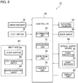
FIG. 6 , thepress brake 10 includes acontroller 58 for controlling a pair of elevatingcylinders 30, aback gauge 38, anoptical safety device 42 and the like based on a machining program, a monitoring program and the like. Thecontroller 58 is constituted by one or a plurality of computers, and alinear encoder 32, afoot switch 36, and the like are connected to thecontroller 58. - The
controller 58 has a memory (not shown) for storing a processing program, a monitoring program, and the like, and a CPU (not shown) for interpreting and executing the processing program, the monitoring program, and the like. Thecontrol device 58 is provided with aninput part 60 for inputting die information, work information, product information, etc., and adisplay part 62 for always displaying the die information, work information, product information, etc. The die information includes information representing the shape and dimensions of theupper die 12, the distance from thelight receiver 52 to the end face of theupper die 12, and the shape and dimensions of thelower die 14. The work information includes information representing the material, shape, dimensions, etc. of the work W, and the product information includes information representing the shape, dimensions, etc. of the product (not shown). - As shown in
FIGS. 5(a) and6 , theinput unit 60 has astart button 64 for starting the programmed operation of thepress brake 10. Theinput unit 60 has afirst changeover switch 66 for switching the threephotodiodes 561 ∼ 563 positioned on the front side to the invalidated state, and asecond changeover switch 68 for switching thephotodiodes 564 positioned closest to theupper mold 12 to the invalidated state. - The
controller 58 has a function as thedetermination unit 70, a function as aninvalidation unit 72, a function as adetection unit 74, and a function as acontrol unit 76. Specific contents of thedetermination unit 70, theinvalidation unit 72, thedetection unit 74, and thecontrol unit 76 are as follows. - As shown in
FIGS. 5(a), 5(b) , and6 , before starting the lowering operation of the upper table 26 (previous), thedetermination unit 70 determines whether or not the shadow of theupper mold 12 by the laser beam B projected on the side of thelight receiver 52 is enlarged to thephotodiode 564, based on the light receiving state (result of light reception) of thephotodiode 12 located in the nearest vicinity of theupper mold 564. Specifically, before starting the descending operation of the upper table 26, thedetermination unit 70 determines whether or not the amount of light received by the photodiode 564 (amount of light received per unit time) is equal to or less than a predetermined first threshold value. If the amount of light received by thephotodiode 564 is equal to or less than the predetermined first threshold value, thedetermination unit 70 determines that the shadow of theupper mold 12 is expanded to thephotodiode 564. If the amount of light received by thephotodiode 564 exceeds the predetermined first threshold value, thedetermination unit 70 determines that the shadow of theupper mold 12 has not expanded to thephotodiode 564. The predetermined first threshold value is a value set in advance for determining whether or not the shadow of theupper mold 12 extends to thephotodiode 564. - As shown in
FIGS. 5 (b) (c) and8 , the invalidatingsection 72 invalidates thephotodiode 564 when it is determined that the shadow of theupper mold 12 is enlarged to thephotodiode 564 located nearest to theupper mold 12. The invalidatingunit 72 invalidates the threephotodiodes 561 ∼ 563 positioned on the front side when thefirst changeover switch 66 is operated by the worker M to perform box bending of the work W. The invalidatingunit 72 invalidates thephotodiode 564 located in the closest vicinity of theupper mold 12 when thesecond changeover switch 68 is changed operation by the worker M. Note that, inFIG. 5(c) , the hatching attached to thephotodiode 564 located in the closest vicinity of theupper mold 12 indicates that thephotodiode 564 is in the invalidated state. - As shown in
FIGS. 3 ,5 (a) , and6 , during the lowering operation of the upper table 26, thedetector 74 detects the presence or absence of foreign body between theupper mold 12 and thelower mold 14 based on the light receiving states (result of light reception) of the effective plurality ofphotodiodes 56. Specifically, thedetector 74 detects whether or not the amount of light received by any effective photodiode 56 (amount of light received per unit time) is equal to or less than a predetermined second threshold value during the lowering operation of the upper table 26. When the amount of light received by anyeffective photodiode 56 is equal to or less than a predetermined second threshold value, thedetection unit 74 detects the presence of foreign body between theupper mold 12 and thelower mold 14. When the amount of light received by all theeffective photodiodes 56 exceeds a predetermined second threshold, adetection part 74 detects no foreign body between theupper mold 12 and thelower mold 14. The predetermined second threshold value is a value set in advance for detecting the presence or absence of a foreign substance between theupper mold 12 and thelower mold 14, and may be the same value as the first threshold value. - The
control unit 76 controls the pair of elevating cylinders 30 (hydraulic unit of the elevating cylinder 30) so as to start the lowering operation of the upper table 26 when a predetermined start signal is output from thefoot switch 36. Thecontrol unit 76 controls the pair of elevatingcylinders 30 so as to reduce the lowering speed of the upper table 26 when the height position of the tip of theupper mold 12 is positioned at a predetermined height position close to the work W while monitoring the detection result from thelinear encoder 32. The predetermined height position is either a first height position or a second height position higher than the first height position. In normal bending processing, the first height position is selected as the predetermined height position. When the threephotodiodes 561 ∼ 563 positioned on the front side and thephotodiode 564 located in the closest vicinity of theupper mold 12 is in the invalidated state, the second height position is selected as the predetermined height position. - When it is detected that there is a foreign substance between the
upper mold 12 and thelower mold 14, thecontrol unit 76 controls the pair of elevating cylinders 30 (hydraulic unit of the elevating cylinder 30) so as to stop the lowering operation of the upper table 26. When the height position of the tip of theupper mold 12 is at a predetermined height position, thecontrol unit 76 need not control the pair of elevatingcylinders 30 so as to stop the lowering operation of the upper table 26. - Here, the
first changeover switch 66, thesecond changeover switch 68, thedetermination unit 70, theinvalidation unit 72, and thedetection unit 74 are regarded as a part of theoptical safety device 42. - Next, the operation of the embodiment of the present invention including the optical monitoring method according to the embodiment of the present invention will be described with reference to
FIG. 7 and the like. An optical monitoring method according to an embodiment of the present invention is a method of monitoring the presence or absence of foreign body between anupper mold 12 and alower mold 14 using alight projector 44 and alight receiver 52, based on the light receiving state of a plurality ofphotodiodes 56 in thelight receiver 52. An optical monitoring method according to an embodiment of the present invention includes a determination step, an invalidation step, a detection step, and a stop step. - The operator M turns on the power of the press brake 10 (Step 101 in
FIG. 7 ) and depresses the start button 64 (Step 102 inFIG. 7 ). Then, six laser beams B are projected from theprojector 44 toward a position directly below theupper mold 12 and the vicinity of its front side. Then, thedetermination unit 70 determines whether or not the shadow of theupper mold 12 by the laser beam B projected on the side of thelight receiver 52 is enlarged to thephotodiode 564 based on the light receiving state of thephotodiode 12 located in the closest vicinity of the upper mold 564 (Step 103 inFIG. 7 , a determination step). - When it is determined that the shadow of the
upper mold 12 extends to the photodiode 564 (Yes in step 103 inFIG. 7 ), the invalidatingsection 72 invalidates the photodiode 564 (Step 104 inFIG. 7 , the invalidating step). When box bending is performed on the work W and thefirst changeover switch 66 is operated by the worker M, the invalidatingsection 72 invalidates the threephotodiodes 561 ∼ 563 positioned on the front side. - After that, when the operator M performs a foot operation of the
foot switch 36, a predetermined start signal is outputted from the foot switch 36 (Step 105 ofFIG. 7 ). Then, thecontrol unit 76 controls the pair of elevatingcylinders 30 to start the lowering operation of the upper table 26 (Step 106 inFIG. 7 ). Then, thedetection unit 74 detects the presence or absence of the foreign body between theupper mold 12 and thelower mold 14 based on the light-receiving states (result of light reception) of the plurality of photodiodes 56 (Step 107 and detection step inFIG. 7 ). - When it is detected that there is no foreign body between the
upper mold 12 and the lower mold 14 (No in step 107 inFIG. 7 ), the lowering operation of the upper table 26 is continued. When the height position of the tip of theupper mold 12 is positioned at a predetermined height position close to the workpiece W, thecontrol unit 76 controls the pair of elevatingcylinders 30 to reduce the lowering speed of the upper table 26. Thus, the work W can be bent by the cooperation (engagement) of theupper mold 12 and the lower mold 14 (Step 108 ofFIG. 7 ). On the other hand, when the presence of foreign body between theupper mold 12 and thelower mold 14 is detected (Yes in step 107 inFIG. 7 ), thecontrol unit 76 controls the pair of elevatingcylinders 30 to stop the lowering operation of the upper table 26 (Step 109 and the stop step inFIG. 7 ). - When the CPU of the
control device 58 determines that no portion to be bent remains in the workpiece W after the bending of the workpiece W (No in step 110 inFIG. 7 ), the CPU finishes the series of processes. On the other hand, when the CPU of thecontrol device 58 determines that a portion to be bent on the workpiece W remains after the bending of the workpiece W (Yes in step 110 inFIG. 7 ), the CPU returns the process to the step 103 inFIG. 7 . - It should be noted that the process of step 103 in
FIG. 7 (decision step) may be omitted. In this case, in the invalidating process of step 104 inFIG. 7 , the invalidatingunit 72 invalidates thephotodiode 564 located nearest to theupper mold 12 when thesecond changeover switch 68 is operated by the operator M. - As described above, the invalidating
unit 72 invalidates thephotodiode 564 when the shadow S of theupper mold 12 extends to thephotodiode 564 located in the closest vicinity of theupper mold 12. Thus, it is prevented that although there is no foreign body between theupper mold 12 and thelower mold 14, the presence of foreign body between theupper mold 12 and thelower mold 14 is erroneously detected by the detectingpart 74 by the shadow S of theupper mold 12. - Therefore, according to the embodiment of the present invention, it is possible to sufficiently prevent the lowering operation of the upper table from being stopped by the shadow S of the
upper die 12 even when the bending is performed with the long upper die 12 attached to thepress brake 10 having the long overall length. Therefore, according to the embodiment of the present invention, thepress brake 10 is equipped with theoptical safety device 42, and the working efficiency (productivity) of thepress brake 10 is improved while sufficiently securing the safety of the bending work. - (Modifications of the embodiment of the present invention) Amodification of the embodiment of the present invention will be described only with respect to a portion different from the above-described embodiment of the present invention.
- As shown in
FIGS. 8 and3 , afirst temperature sensor 78 for measuring the temperature of the member at the tip of theupper mold 12 and asecond temperature sensor 80 for measuring the environmental temperature in the factory are connected to thecontrol device 58. Thecontrol device 58 has a function as thecalculation unit 82 and a function as thedetermination unit 84 in place of the function as thedetermination unit 70. The specific contents of thecalculation unit 82 and thedetermination unit 84 are as follows. - As shown in
FIGS. 5 (a) and 5 (b) andFIG. 8 , thecalculation unit 82 calculates the enlargement amount of the shadow S of theupper mold 12 based on the member temperature of the tip of theupper mold 12, which is a measurement result from thefirst temperature sensor 78, the environmental temperature in the factory, which is a measurement result from thesecond temperature sensor 80, the length of theupper mold 12, and the distance from thelight receiver 52 to the end surface of theupper mold 12. The enlargement amount of the shadow S of theupper mold 12 refers to the maximum amount by which the shadow S of theupper mold 12 protrudes from the outline of theupper mold 12. It is preferable that thecalculation unit 82 calculates the enlargement amount of the shadow S of theupper mold 12 in consideration of the distance from thelight receiver 52 to the end face of theupper mold 12. Thecalculation unit 82 may calculate the enlargement amount of the shadow S of theupper mold 12 based on the captured image captured from the side of theprojector 44 by the camera (not shown). - Just before starting the lowering operation of the upper table 26 (Previous), a
determination part 84 determines whether or not the shadow S of theupper mold 12 is enlarged up to aphotodiode 564 positioned nearest to theupper mold 12 based on the calculated enlargement amount of the shadow S of theupper mold 12. Specifically, before starting the lowering operation of the upper table 26, thedetermination unit 84 determines whether the enlargement amount of the shadow S of theupper mold 12 is equal to or larger than a predetermined enlargement amount. If the enlargement amount of the shadow S of theupper mold 12 is equal to or larger than a predetermined enlargement amount, thedetermination unit 84 determines that the shadow of theupper mold 12 is enlarged up to thephotodiode 564. When the enlargement amount of the shadow S of theupper mold 12 is less than a predetermined enlargement amount, thedetermination part 84 determines that the shadow of theupper mold 12 is not enlarged to thephotodiode 564. The predetermined enlargement amount is a preset enlargement amount for determining whether or not the shadow of theupper mold 12 is enlarged to thephotodiode 564. - In the modification of the embodiment of the present invention, immediately before the processing of step 103 in
FIG. 7 , thecalculation unit 82 calculates the enlargement amount of the shadow S of the upper mold 12 (calculation step) . In other words, the optical monitoring method according to a modification of the embodiment of the present invention includes a calculation step immediately before the processing of step 103. In the process of step S 103 inFIG. 7 , thedetermination unit 84 determines, based on the calculated enlargement amount of the shadow S of theupper mold 12, whether or not the shadow S of theupper mold 12 has been enlarged up to thephotodiode 564 located in the vicinity of the upper mold 12 (decision step). - The modification of the embodiment of the present invention also produces the same effect as the embodiment of the present invention described above.
- It should be noted that the present invention is not limited to the description of the above-described embodiments, and may be implemented in various forms, for example, as follows.
- The
determination unit 70 may determine whether or not the shadow of themold 12 is enlarged to any of the fourphotodiodes photodiode 564 located in the closest vicinity of theupper mold 12 but also the light receiving states of the three photodiodes 561,562,564,565. Similarly, thedetermination unit 84 may determine, based on the calculated enlargement amount of the shadow S of theupper mold 12, whether or not the shadow S of theupper mold 12 has been enlarged to any one of the photodiodes 561,562,565 in addition to thephotodiode 564 located in the vicinity of theupper mold 12. - The scope of rights included in the present invention is not limited to the above-described embodiments.
- According to the present invention, even when bending is performed in a state where a long upper die is attached to the press brake having a long overall length, the relative lowering operation of the upper table can be sufficiently prevented from being stopped by the shadow of the upper die. Therefore, according to the present invention, the press brake can be equipped with an optical safety device, and the working efficiency (productivity) of the press brake can be enhanced while sufficiently securing the safety of the bending work.
Claims (7)
- An optical safety device for a press brake comprising:a projector provided on one side in a length direction of an upper table in the press brake for projecting a monitoring light directly under an upper die and toward the other side in the length direction of the upper table;a photodetector provided on the other side in the length direction of the upper table and having a plurality of light receiving element for outputting electric signals corresponding to amount of the monitoring light and receiving the monitoring light; andan invalidation unit for invalidating the photodetectors when a shadow of the upper die projected on the photodetector by the monitoring light extends to the photodetectors positioned in a vicinity of the upper die.
- The optical safety device for the press brake as claimed in claim 1, further comprising a determination unit for determining whether the shadow of the upper mold extends to the light receiving element located in the vicinity of the upper mold, and the invalidation unit for invalidating the light receiving element when it is determined that the shadow of the upper mold extends to the light receiving element located in the vicinity of the upper mold.
- The optical safety device for the press brake as claimed in claim 2, wherein the determination unit determines, based on a light receiving state of the light receiving element located in the vicinity of the upper mold, whether or not the shadow of the upper mold extends to the light receiving element located in the vicinity of the upper mold.
- The optical safety device for the press brake as claimed in claim 2, wherein the optical safety device is provided with a calculation unit for calculating an amount of enlargement of the shadow of the upper mold, and the determination unit determines whether or not the shadow of the upper mold is enlarged to the light receiving element located in the vicinity of the upper mold based on the calculated amount of enlargement of the shadow of the upper mold.
- The optical safety device for the press brake as claimed in claim 1, wherein the optical safety device is provided with a changeover switch for switching the light receiving element positioned in the vicinity of the upper die to an invalidated state, and the invalidating unit invalidates the light receiving element positioned in the vicinity of the upper die when the changeover switch is operated.
- A press brake provided with one of the optical safety device for press brake claimed in claim 1-5.
- An optical monitoring method, by using a light projector provided on one side in a length direction of an upper table in a press brake for projecting monitoring light directly under an upper die toward other side in the length direction of the upper table and a light receiving element provided on the other side in the length direction of the upper table and receiving the monitoring light, for monitoring a presence or an absence of a foreign substance between the upper die and a lower die based on a light receiving states of the light receiving element in a photodetector, comprising;
a step of determining whether or not a shadow of the upper die due to the monitoring light projected on the light receiving element side is expanded to the light receiving element located in the nearest vicinity of the upper die, before the press brake starts a lowering operation of the upper table relative to the lower table in the press brake, and
a step of invalidating the light receiving element when it is determined that the shadow of the upper mold extends to the light receiving element positioned nearest to the upper mold.
Applications Claiming Priority (2)
| Application Number | Priority Date | Filing Date | Title |
|---|---|---|---|
| JP2018046297A JP6572338B1 (en) | 2018-03-14 | 2018-03-14 | Optical safety device for press brake, press brake, and optical monitoring method |
| PCT/JP2019/009951 WO2019176924A1 (en) | 2018-03-14 | 2019-03-12 | Optical safety device for press brakes, press brake, and optical monitoring method |
Publications (3)
| Publication Number | Publication Date |
|---|---|
| EP3766596A1 true EP3766596A1 (en) | 2021-01-20 |
| EP3766596A4 EP3766596A4 (en) | 2021-12-15 |
| EP3766596B1 EP3766596B1 (en) | 2024-09-25 |
Family
ID=67844843
Family Applications (1)
| Application Number | Title | Priority Date | Filing Date |
|---|---|---|---|
| EP19766505.2A Active EP3766596B1 (en) | 2018-03-14 | 2019-03-12 | Optical safety device for press brakes, press brake, and optical monitoring method |
Country Status (5)
| Country | Link |
|---|---|
| US (1) | US11623267B2 (en) |
| EP (1) | EP3766596B1 (en) |
| JP (1) | JP6572338B1 (en) |
| CN (1) | CN111867746B (en) |
| WO (1) | WO2019176924A1 (en) |
Families Citing this family (3)
| Publication number | Priority date | Publication date | Assignee | Title |
|---|---|---|---|---|
| CN112620449B (en) * | 2020-12-09 | 2024-05-10 | 芜湖玉泰汽车制动有限公司 | Brake disc stamping equipment capable of automatically stopping in emergency |
| CN113145697B (en) * | 2021-04-18 | 2022-06-03 | 南京盛大重工机械有限公司 | Single servo pump control electro-hydraulic bending machine |
| EP4527516A1 (en) * | 2023-09-20 | 2025-03-26 | Fiessler Elektronik GmbH & Co. KG | Bending machine and method for operating a bending machine |
Family Cites Families (19)
| Publication number | Priority date | Publication date | Assignee | Title |
|---|---|---|---|---|
| US5015840B1 (en) * | 1990-01-09 | 1995-04-11 | Scient Technologies Inc | Self-checking light curtain system and method of operation. |
| DE19604900C2 (en) | 1996-02-10 | 2000-02-03 | Hermann Wegener | Safety device for hand-operated machine tools, especially for press brakes |
| JPH10156595A (en) * | 1996-11-26 | 1998-06-16 | Komatsu Ltd | Optical axis invalidation control device of beam type safety device |
| JP2003218679A (en) | 2002-01-25 | 2003-07-31 | Keyence Corp | Multi-optical-axis photoelectric type safety device |
| ES2260550T3 (en) * | 2002-07-31 | 2006-11-01 | FIESSLER ELEKTRONIK GMBH & CO. KG | PROTECTION DEVICE FOR MACHINES, SUCH AS FOLDING MACHINES, SHEARERS, TROQUELADORAS OR SIMILAR. |
| DE10247136A1 (en) * | 2002-10-09 | 2004-04-22 | Sick Ag | Protection device for monitoring a protected area to be moved with a component |
| DE20217426U1 (en) * | 2002-11-05 | 2003-01-16 | Pilz GmbH & Co., 73760 Ostfildern | Safety device for a machine, in particular for a bending press |
| JP4958557B2 (en) * | 2003-12-11 | 2012-06-20 | デーヴィス,ケヴィン,ステファン | Control system |
| JP2005296966A (en) * | 2004-04-07 | 2005-10-27 | Amada Co Ltd | Bending method and bending device |
| US8692877B2 (en) * | 2005-06-20 | 2014-04-08 | Lazer Safe Pty Ltd | Imaging and safety system and method for an industrial machine |
| JP2007203310A (en) | 2006-01-31 | 2007-08-16 | Amada Co Ltd | Bending apparatus |
| ATE518220T1 (en) * | 2006-09-29 | 2011-08-15 | Sick Ag | OPTOELECTRONIC SAFETY SYSTEM |
| ATE552514T1 (en) * | 2006-12-02 | 2012-04-15 | Sick Ag | OPTOELECTRONIC MULTILEVEL SENSOR AND METHOD FOR DETECTING OBJECTS |
| EP2624017B1 (en) * | 2012-02-02 | 2020-06-17 | Rockwell Automation Switzerland GmbH | Integrated laser alignment aid using multiple laser spots out of one single laser |
| ES2611002T3 (en) | 2014-05-03 | 2017-05-04 | Fiessler Elektronik Gmbh & Co. Kg | Forming device and procedure for the operation of a forming device |
| JP2016128180A (en) | 2015-01-09 | 2016-07-14 | 株式会社アマダホールディングス | Safety device for press brake and press brake |
| EP3081960B1 (en) * | 2015-04-13 | 2023-03-22 | Rockwell Automation Switzerland GmbH | Time-of-flight safety photoelectric barrier and method of monitoring a protective field |
| DE102016100445A1 (en) * | 2016-01-12 | 2017-07-13 | Pilz Gmbh & Co. Kg | Safety device and method for monitoring a machine |
| JP6243954B2 (en) * | 2016-04-14 | 2017-12-06 | 株式会社アマダホールディングス | Press brake safety device |
-
2018
- 2018-03-14 JP JP2018046297A patent/JP6572338B1/en active Active
-
2019
- 2019-03-12 WO PCT/JP2019/009951 patent/WO2019176924A1/en not_active Ceased
- 2019-03-12 US US16/979,599 patent/US11623267B2/en active Active
- 2019-03-12 EP EP19766505.2A patent/EP3766596B1/en active Active
- 2019-03-12 CN CN201980018927.9A patent/CN111867746B/en active Active
Also Published As
| Publication number | Publication date |
|---|---|
| CN111867746B (en) | 2022-10-28 |
| EP3766596A4 (en) | 2021-12-15 |
| US20210039156A1 (en) | 2021-02-11 |
| JP6572338B1 (en) | 2019-09-04 |
| US11623267B2 (en) | 2023-04-11 |
| EP3766596B1 (en) | 2024-09-25 |
| WO2019176924A1 (en) | 2019-09-19 |
| JP2019155433A (en) | 2019-09-19 |
| CN111867746A (en) | 2020-10-30 |
Similar Documents
| Publication | Publication Date | Title |
|---|---|---|
| EP3766596B1 (en) | Optical safety device for press brakes, press brake, and optical monitoring method | |
| US6644080B2 (en) | Press brake worksheet positioning system | |
| US9895769B2 (en) | Laser processing device having function for avoiding interference at the time of nozzle approach | |
| JP2003053597A (en) | Protective device for machine such as, in particular, bending press machine, cutting machine and punching machine | |
| CN107876967B (en) | Laser-processing system | |
| KR101942889B1 (en) | Safety device of press brake and control method of press brake | |
| EP4596131A1 (en) | Press brake, bending processing system, and method for controlling sensor movement | |
| JP7269744B2 (en) | Safety device for press brake, press brake, and safety monitoring method | |
| JP6812184B2 (en) | Press brake and work presence / absence determination method | |
| JP6498943B2 (en) | Safety monitoring device for press brake, press brake, and safety monitoring method | |
| JP2004174500A (en) | Bending device and sheeting system | |
| US11980926B2 (en) | Optical safety device, press brake, and workpiece detection method | |
| JP2021109219A (en) | Optical safety device for press brake, press brake, and optical monitoring method | |
| ITPN980075A1 (en) | DEVICE TO AVOID ACCIDENTS TO THE OPERATOR OF A BENDER | |
| JP2024149134A (en) | Mold changing device and mold detection method | |
| JP2017039149A (en) | Magnet plate removal forgetting prevention device and removal forgetting prevention method | |
| KR102764393B1 (en) | Outrigger and control method for outtrigger | |
| JPH04147719A (en) | Device for working sheet material | |
| JP2023160317A (en) | Press machine safety device and press machine safety control method | |
| JP2006122956A (en) | Bending apparatus | |
| JP2017213594A (en) | Controller, forging machine, and control method | |
| JP2018079490A (en) | Bending processor and bending method | |
| JP2003094116A (en) | Bending machine |
Legal Events
| Date | Code | Title | Description |
|---|---|---|---|
| STAA | Information on the status of an ep patent application or granted ep patent |
Free format text: STATUS: THE INTERNATIONAL PUBLICATION HAS BEEN MADE |
|
| PUAI | Public reference made under article 153(3) epc to a published international application that has entered the european phase |
Free format text: ORIGINAL CODE: 0009012 |
|
| STAA | Information on the status of an ep patent application or granted ep patent |
Free format text: STATUS: REQUEST FOR EXAMINATION WAS MADE |
|
| 17P | Request for examination filed |
Effective date: 20200910 |
|
| AK | Designated contracting states |
Kind code of ref document: A1 Designated state(s): AL AT BE BG CH CY CZ DE DK EE ES FI FR GB GR HR HU IE IS IT LI LT LU LV MC MK MT NL NO PL PT RO RS SE SI SK SM TR |
|
| AX | Request for extension of the european patent |
Extension state: BA ME |
|
| DAV | Request for validation of the european patent (deleted) | ||
| DAX | Request for extension of the european patent (deleted) | ||
| A4 | Supplementary search report drawn up and despatched |
Effective date: 20211111 |
|
| RIC1 | Information provided on ipc code assigned before grant |
Ipc: B30B 15/00 20060101ALI20211105BHEP Ipc: B21D 5/02 20060101AFI20211105BHEP |
|
| P01 | Opt-out of the competence of the unified patent court (upc) registered |
Effective date: 20230527 |
|
| GRAP | Despatch of communication of intention to grant a patent |
Free format text: ORIGINAL CODE: EPIDOSNIGR1 |
|
| STAA | Information on the status of an ep patent application or granted ep patent |
Free format text: STATUS: GRANT OF PATENT IS INTENDED |
|
| INTG | Intention to grant announced |
Effective date: 20240110 |
|
| GRAJ | Information related to disapproval of communication of intention to grant by the applicant or resumption of examination proceedings by the epo deleted |
Free format text: ORIGINAL CODE: EPIDOSDIGR1 |
|
| STAA | Information on the status of an ep patent application or granted ep patent |
Free format text: STATUS: REQUEST FOR EXAMINATION WAS MADE |
|
| INTC | Intention to grant announced (deleted) | ||
| GRAP | Despatch of communication of intention to grant a patent |
Free format text: ORIGINAL CODE: EPIDOSNIGR1 |
|
| STAA | Information on the status of an ep patent application or granted ep patent |
Free format text: STATUS: GRANT OF PATENT IS INTENDED |
|
| INTG | Intention to grant announced |
Effective date: 20240610 |
|
| GRAS | Grant fee paid |
Free format text: ORIGINAL CODE: EPIDOSNIGR3 |
|
| GRAA | (expected) grant |
Free format text: ORIGINAL CODE: 0009210 |
|
| STAA | Information on the status of an ep patent application or granted ep patent |
Free format text: STATUS: THE PATENT HAS BEEN GRANTED |
|
| AK | Designated contracting states |
Kind code of ref document: B1 Designated state(s): AL AT BE BG CH CY CZ DE DK EE ES FI FR GB GR HR HU IE IS IT LI LT LU LV MC MK MT NL NO PL PT RO RS SE SI SK SM TR |
|
| REG | Reference to a national code |
Ref country code: GB Ref legal event code: FG4D |
|
| REG | Reference to a national code |
Ref country code: CH Ref legal event code: EP |
|
| REG | Reference to a national code |
Ref country code: DE Ref legal event code: R096 Ref document number: 602019059457 Country of ref document: DE |
|
| REG | Reference to a national code |
Ref country code: IE Ref legal event code: FG4D |
|
| REG | Reference to a national code |
Ref country code: LT Ref legal event code: MG9D |
|
| PG25 | Lapsed in a contracting state [announced via postgrant information from national office to epo] |
Ref country code: NO Free format text: LAPSE BECAUSE OF FAILURE TO SUBMIT A TRANSLATION OF THE DESCRIPTION OR TO PAY THE FEE WITHIN THE PRESCRIBED TIME-LIMIT Effective date: 20241225 |
|
| PG25 | Lapsed in a contracting state [announced via postgrant information from national office to epo] |
Ref country code: GR Free format text: LAPSE BECAUSE OF FAILURE TO SUBMIT A TRANSLATION OF THE DESCRIPTION OR TO PAY THE FEE WITHIN THE PRESCRIBED TIME-LIMIT Effective date: 20241226 Ref country code: FI Free format text: LAPSE BECAUSE OF FAILURE TO SUBMIT A TRANSLATION OF THE DESCRIPTION OR TO PAY THE FEE WITHIN THE PRESCRIBED TIME-LIMIT Effective date: 20240925 |
|
| PG25 | Lapsed in a contracting state [announced via postgrant information from national office to epo] |
Ref country code: BG Free format text: LAPSE BECAUSE OF FAILURE TO SUBMIT A TRANSLATION OF THE DESCRIPTION OR TO PAY THE FEE WITHIN THE PRESCRIBED TIME-LIMIT Effective date: 20240925 |
|
| PG25 | Lapsed in a contracting state [announced via postgrant information from national office to epo] |
Ref country code: LV Free format text: LAPSE BECAUSE OF FAILURE TO SUBMIT A TRANSLATION OF THE DESCRIPTION OR TO PAY THE FEE WITHIN THE PRESCRIBED TIME-LIMIT Effective date: 20240925 |
|
| PG25 | Lapsed in a contracting state [announced via postgrant information from national office to epo] |
Ref country code: RS Free format text: LAPSE BECAUSE OF FAILURE TO SUBMIT A TRANSLATION OF THE DESCRIPTION OR TO PAY THE FEE WITHIN THE PRESCRIBED TIME-LIMIT Effective date: 20241225 |
|
| REG | Reference to a national code |
Ref country code: NL Ref legal event code: MP Effective date: 20240925 |
|
| PG25 | Lapsed in a contracting state [announced via postgrant information from national office to epo] |
Ref country code: RS Free format text: LAPSE BECAUSE OF FAILURE TO SUBMIT A TRANSLATION OF THE DESCRIPTION OR TO PAY THE FEE WITHIN THE PRESCRIBED TIME-LIMIT Effective date: 20241225 Ref country code: NO Free format text: LAPSE BECAUSE OF FAILURE TO SUBMIT A TRANSLATION OF THE DESCRIPTION OR TO PAY THE FEE WITHIN THE PRESCRIBED TIME-LIMIT Effective date: 20241225 Ref country code: LV Free format text: LAPSE BECAUSE OF FAILURE TO SUBMIT A TRANSLATION OF THE DESCRIPTION OR TO PAY THE FEE WITHIN THE PRESCRIBED TIME-LIMIT Effective date: 20240925 Ref country code: GR Free format text: LAPSE BECAUSE OF FAILURE TO SUBMIT A TRANSLATION OF THE DESCRIPTION OR TO PAY THE FEE WITHIN THE PRESCRIBED TIME-LIMIT Effective date: 20241226 Ref country code: FI Free format text: LAPSE BECAUSE OF FAILURE TO SUBMIT A TRANSLATION OF THE DESCRIPTION OR TO PAY THE FEE WITHIN THE PRESCRIBED TIME-LIMIT Effective date: 20240925 Ref country code: BG Free format text: LAPSE BECAUSE OF FAILURE TO SUBMIT A TRANSLATION OF THE DESCRIPTION OR TO PAY THE FEE WITHIN THE PRESCRIBED TIME-LIMIT Effective date: 20240925 |
|
| REG | Reference to a national code |
Ref country code: AT Ref legal event code: MK05 Ref document number: 1726246 Country of ref document: AT Kind code of ref document: T Effective date: 20240925 |
|
| PG25 | Lapsed in a contracting state [announced via postgrant information from national office to epo] |
Ref country code: NL Free format text: LAPSE BECAUSE OF FAILURE TO SUBMIT A TRANSLATION OF THE DESCRIPTION OR TO PAY THE FEE WITHIN THE PRESCRIBED TIME-LIMIT Effective date: 20240925 |
|
| PG25 | Lapsed in a contracting state [announced via postgrant information from national office to epo] |
Ref country code: IS Free format text: LAPSE BECAUSE OF FAILURE TO SUBMIT A TRANSLATION OF THE DESCRIPTION OR TO PAY THE FEE WITHIN THE PRESCRIBED TIME-LIMIT Effective date: 20250125 Ref country code: PT Free format text: LAPSE BECAUSE OF FAILURE TO SUBMIT A TRANSLATION OF THE DESCRIPTION OR TO PAY THE FEE WITHIN THE PRESCRIBED TIME-LIMIT Effective date: 20250127 |
|
| PG25 | Lapsed in a contracting state [announced via postgrant information from national office to epo] |
Ref country code: RO Free format text: LAPSE BECAUSE OF FAILURE TO SUBMIT A TRANSLATION OF THE DESCRIPTION OR TO PAY THE FEE WITHIN THE PRESCRIBED TIME-LIMIT Effective date: 20240925 Ref country code: SM Free format text: LAPSE BECAUSE OF FAILURE TO SUBMIT A TRANSLATION OF THE DESCRIPTION OR TO PAY THE FEE WITHIN THE PRESCRIBED TIME-LIMIT Effective date: 20240925 |
|
| PG25 | Lapsed in a contracting state [announced via postgrant information from national office to epo] |
Ref country code: ES Free format text: LAPSE BECAUSE OF FAILURE TO SUBMIT A TRANSLATION OF THE DESCRIPTION OR TO PAY THE FEE WITHIN THE PRESCRIBED TIME-LIMIT Effective date: 20240925 |
|
| PG25 | Lapsed in a contracting state [announced via postgrant information from national office to epo] |
Ref country code: EE Free format text: LAPSE BECAUSE OF FAILURE TO SUBMIT A TRANSLATION OF THE DESCRIPTION OR TO PAY THE FEE WITHIN THE PRESCRIBED TIME-LIMIT Effective date: 20240925 Ref country code: AT Free format text: LAPSE BECAUSE OF FAILURE TO SUBMIT A TRANSLATION OF THE DESCRIPTION OR TO PAY THE FEE WITHIN THE PRESCRIBED TIME-LIMIT Effective date: 20240925 |
|
| PG25 | Lapsed in a contracting state [announced via postgrant information from national office to epo] |
Ref country code: CZ Free format text: LAPSE BECAUSE OF FAILURE TO SUBMIT A TRANSLATION OF THE DESCRIPTION OR TO PAY THE FEE WITHIN THE PRESCRIBED TIME-LIMIT Effective date: 20240925 Ref country code: PL Free format text: LAPSE BECAUSE OF FAILURE TO SUBMIT A TRANSLATION OF THE DESCRIPTION OR TO PAY THE FEE WITHIN THE PRESCRIBED TIME-LIMIT Effective date: 20240925 |
|
| PG25 | Lapsed in a contracting state [announced via postgrant information from national office to epo] |
Ref country code: SK Free format text: LAPSE BECAUSE OF FAILURE TO SUBMIT A TRANSLATION OF THE DESCRIPTION OR TO PAY THE FEE WITHIN THE PRESCRIBED TIME-LIMIT Effective date: 20240925 |
|
| REG | Reference to a national code |
Ref country code: DE Ref legal event code: R097 Ref document number: 602019059457 Country of ref document: DE |
|
| PG25 | Lapsed in a contracting state [announced via postgrant information from national office to epo] |
Ref country code: DK Free format text: LAPSE BECAUSE OF FAILURE TO SUBMIT A TRANSLATION OF THE DESCRIPTION OR TO PAY THE FEE WITHIN THE PRESCRIBED TIME-LIMIT Effective date: 20240925 |
|
| PLBE | No opposition filed within time limit |
Free format text: ORIGINAL CODE: 0009261 |
|
| STAA | Information on the status of an ep patent application or granted ep patent |
Free format text: STATUS: NO OPPOSITION FILED WITHIN TIME LIMIT |
|
| 26N | No opposition filed |
Effective date: 20250626 |
|
| PG25 | Lapsed in a contracting state [announced via postgrant information from national office to epo] |
Ref country code: SE Free format text: LAPSE BECAUSE OF FAILURE TO SUBMIT A TRANSLATION OF THE DESCRIPTION OR TO PAY THE FEE WITHIN THE PRESCRIBED TIME-LIMIT Effective date: 20240925 |
|
| PG25 | Lapsed in a contracting state [announced via postgrant information from national office to epo] |
Ref country code: MC Free format text: LAPSE BECAUSE OF FAILURE TO SUBMIT A TRANSLATION OF THE DESCRIPTION OR TO PAY THE FEE WITHIN THE PRESCRIBED TIME-LIMIT Effective date: 20240925 |
|
| REG | Reference to a national code |
Ref country code: CH Ref legal event code: H13 Free format text: ST27 STATUS EVENT CODE: U-0-0-H10-H13 (AS PROVIDED BY THE NATIONAL OFFICE) Effective date: 20251023 |
|
| PG25 | Lapsed in a contracting state [announced via postgrant information from national office to epo] |
Ref country code: LU Free format text: LAPSE BECAUSE OF NON-PAYMENT OF DUE FEES Effective date: 20250312 |
|
| REG | Reference to a national code |
Ref country code: BE Ref legal event code: MM Effective date: 20250331 |
|
| PG25 | Lapsed in a contracting state [announced via postgrant information from national office to epo] |
Ref country code: HR Free format text: LAPSE BECAUSE OF FAILURE TO SUBMIT A TRANSLATION OF THE DESCRIPTION OR TO PAY THE FEE WITHIN THE PRESCRIBED TIME-LIMIT Effective date: 20240925 |
|
| PG25 | Lapsed in a contracting state [announced via postgrant information from national office to epo] |
Ref country code: BE Free format text: LAPSE BECAUSE OF NON-PAYMENT OF DUE FEES Effective date: 20250331 |
|
| PG25 | Lapsed in a contracting state [announced via postgrant information from national office to epo] |
Ref country code: CH Free format text: LAPSE BECAUSE OF NON-PAYMENT OF DUE FEES Effective date: 20250331 |
|
| PG25 | Lapsed in a contracting state [announced via postgrant information from national office to epo] |
Ref country code: IE Free format text: LAPSE BECAUSE OF NON-PAYMENT OF DUE FEES Effective date: 20250312 |
|
| PGFP | Annual fee paid to national office [announced via postgrant information from national office to epo] |
Ref country code: GB Payment date: 20260324 Year of fee payment: 8 |
|
| PGFP | Annual fee paid to national office [announced via postgrant information from national office to epo] |
Ref country code: DE Payment date: 20260319 Year of fee payment: 8 |
|
| PGFP | Annual fee paid to national office [announced via postgrant information from national office to epo] |
Ref country code: IT Payment date: 20260324 Year of fee payment: 8 |
|
| PGFP | Annual fee paid to national office [announced via postgrant information from national office to epo] |
Ref country code: FR Payment date: 20260323 Year of fee payment: 8 |