EP3766442A1 - Shaft for in vivo recovery mechanism - Google Patents
Shaft for in vivo recovery mechanism Download PDFInfo
- Publication number
- EP3766442A1 EP3766442A1 EP18909838.7A EP18909838A EP3766442A1 EP 3766442 A1 EP3766442 A1 EP 3766442A1 EP 18909838 A EP18909838 A EP 18909838A EP 3766442 A1 EP3766442 A1 EP 3766442A1
- Authority
- EP
- European Patent Office
- Prior art keywords
- shaft
- strand
- recovery mechanism
- vivo recovery
- present
- Prior art date
- Legal status (The legal status is an assumption and is not a legal conclusion. Google has not performed a legal analysis and makes no representation as to the accuracy of the status listed.)
- Granted
Links
Images





Classifications
-
- A—HUMAN NECESSITIES
- A61—MEDICAL OR VETERINARY SCIENCE; HYGIENE
- A61B—DIAGNOSIS; SURGERY; IDENTIFICATION
- A61B17/00—Surgical instruments, devices or methods
- A61B17/32—Surgical cutting instruments
- A61B17/3205—Excision instruments
- A61B17/3207—Atherectomy devices working by cutting or abrading; Similar devices specially adapted for non-vascular obstructions
- A61B17/320758—Atherectomy devices working by cutting or abrading; Similar devices specially adapted for non-vascular obstructions with a rotating cutting instrument, e.g. motor driven
-
- A—HUMAN NECESSITIES
- A61—MEDICAL OR VETERINARY SCIENCE; HYGIENE
- A61B—DIAGNOSIS; SURGERY; IDENTIFICATION
- A61B17/00—Surgical instruments, devices or methods
- A61B17/22—Implements for squeezing-off ulcers or the like on inner organs of the body; Implements for scraping-out cavities of body organs, e.g. bones; for invasive removal or destruction of calculus using mechanical vibrations; for removing obstructions in blood vessels, not otherwise provided for
-
- A—HUMAN NECESSITIES
- A61—MEDICAL OR VETERINARY SCIENCE; HYGIENE
- A61B—DIAGNOSIS; SURGERY; IDENTIFICATION
- A61B17/00—Surgical instruments, devices or methods
- A61B17/32—Surgical cutting instruments
- A61B17/3205—Excision instruments
- A61B17/3207—Atherectomy devices working by cutting or abrading; Similar devices specially adapted for non-vascular obstructions
-
- A—HUMAN NECESSITIES
- A61—MEDICAL OR VETERINARY SCIENCE; HYGIENE
- A61B—DIAGNOSIS; SURGERY; IDENTIFICATION
- A61B17/00—Surgical instruments, devices or methods
- A61B17/32—Surgical cutting instruments
- A61B17/3205—Excision instruments
- A61B17/3207—Atherectomy devices working by cutting or abrading; Similar devices specially adapted for non-vascular obstructions
- A61B17/320783—Atherectomy devices working by cutting or abrading; Similar devices specially adapted for non-vascular obstructions through side-hole, e.g. sliding or rotating cutter inside catheter
-
- A—HUMAN NECESSITIES
- A61—MEDICAL OR VETERINARY SCIENCE; HYGIENE
- A61B—DIAGNOSIS; SURGERY; IDENTIFICATION
- A61B17/00—Surgical instruments, devices or methods
- A61B2017/00367—Details of actuation of instruments, e.g. relations between pushing buttons, or the like, and activation of the tool, working tip, or the like
- A61B2017/00398—Details of actuation of instruments, e.g. relations between pushing buttons, or the like, and activation of the tool, working tip, or the like using powered actuators, e.g. stepper motors, solenoids
-
- A—HUMAN NECESSITIES
- A61—MEDICAL OR VETERINARY SCIENCE; HYGIENE
- A61B—DIAGNOSIS; SURGERY; IDENTIFICATION
- A61B17/00—Surgical instruments, devices or methods
- A61B2017/00681—Aspects not otherwise provided for
- A61B2017/00685—Archimedes screw
-
- A—HUMAN NECESSITIES
- A61—MEDICAL OR VETERINARY SCIENCE; HYGIENE
- A61B—DIAGNOSIS; SURGERY; IDENTIFICATION
- A61B17/00—Surgical instruments, devices or methods
- A61B2017/00831—Material properties
- A61B2017/00867—Material properties shape memory effect
-
- A—HUMAN NECESSITIES
- A61—MEDICAL OR VETERINARY SCIENCE; HYGIENE
- A61B—DIAGNOSIS; SURGERY; IDENTIFICATION
- A61B17/00—Surgical instruments, devices or methods
- A61B17/32—Surgical cutting instruments
- A61B17/320016—Endoscopic cutting instruments, e.g. arthroscopes, resectoscopes
- A61B17/32002—Endoscopic cutting instruments, e.g. arthroscopes, resectoscopes with continuously rotating, oscillating or reciprocating cutting instruments
- A61B2017/320032—Details of the rotating or oscillating shaft, e.g. using a flexible shaft
-
- A—HUMAN NECESSITIES
- A61—MEDICAL OR VETERINARY SCIENCE; HYGIENE
- A61B—DIAGNOSIS; SURGERY; IDENTIFICATION
- A61B17/00—Surgical instruments, devices or methods
- A61B17/32—Surgical cutting instruments
- A61B2017/320064—Surgical cutting instruments with tissue or sample retaining means
Definitions
- the present invention relates to a shaft for an in vivo recovery mechanism for use in an in vivo recovery mechanism that removes a substance from a body lumen.
- Patent Document 1 a device for removing a substance from a body lumen is described which includes a catheter having a proximal end, a distal end, and a catheter lumen that extends therethrough, a cutter assembly which is rotatably joined to the distal end of the catheter, and a rotatable torque shaft having a first end, which extends through the catheter lumen and is joined to the cutter assembly, and a second end which is configured so as to be joined to a rotation mechanism, wherein an outer coil is provided on an outer surface of the torque shaft, and the outer coil is spirally formed on the outer surface of the torque shaft such that a substance inside a body lumen is transported in the proximal direction when the torque shaft is rotated (see FIG. 20, etc.).
- Patent Document 1 Japanese Unexamined Patent Application Publication No. 2013-138877
- the device described in Patent Document 1 discharges a substance inside a body lumen (hereinafter referred to as “substance in the body”) to the outside of a patient's body by means of the outer coil spirally formed on the torque shaft, and the performance for recovering and transporting the substance in the body depends on the outer coil.
- the present invention has been made in response to the above problems associated with the conventional technique, and an object of the present invention is to provide a shaft for an in vivo recovery mechanism that improves the recovery and transport performance of an in vivo recovery mechanism to enable in vivo recovery work in procedures and surgeries to be quickly and reliably performed.
- a shaft for an in vivo recovery mechanism includes a shaft, and a side wire sparsely wound onto an outer circumference of the shaft, and having protruding and recessed parts on an outer circumferential surface thereof.
- a second aspect of the present invention is the shaft for an in vivo recovery mechanism according to the first aspect, wherein the side wire is constituted by a first strand formed by twisting a plurality of first wires, and the protruding and recessed parts of the side wire are formed from an outline of the first strand.
- a third aspect of the present invention is the shaft for an in vivo recovery mechanism according to the second aspect, wherein a twisting direction of the first strand is the same direction as a winding direction of the side wire onto the shaft.
- a fourth aspect of the present invention is the shaft for an in vivo recovery mechanism according to the second aspect or the third aspect, wherein protruding and recessed parts are formed on an outer circumferential surface of the wires constituting the first strand.
- a fifth aspect of the present invention is the shaft for an in vivo recovery mechanism according to any one of the first aspect to the fourth aspect, wherein the protruding and recessed parts have protruding parts and recessed parts, which extend along a direction substantially perpendicular to a long axis direction of the shaft, in a direction parallel to the long axis direction.
- a sixth aspect of the present invention is the shaft for an in vivo recovery mechanism according to any one of the first aspect to the fifth aspect, wherein the shaft is constituted by a second strand formed by twisting a plurality of second wires.
- a seventh aspect of the present invention is the shaft for an in vivo recovery mechanism of any one of the first aspect to the fifth aspect, wherein the shaft is constituted by a hollow strand formed by twisting a plurality of third wires.
- the shaft for an in vivo recovery mechanism is provided with a shaft, and a side wire sparsely wound onto the outer circumference of the shaft and having protruding and recessed parts on the outer circumferential surface thereof, and therefore, when rotating the shaft for an in vivo recovery mechanism, a substance in the body is caught between the sparsely wound side wire on the shaft and held by the protruding and recessed parts formed on the side wire, and the performance for recovering and transporting the substance in the body can be improved.
- the second aspect of the present invention is the shaft for an in vivo recovery mechanism according to the first aspect, wherein the side wire is constituted by a first strand formed by twisting a plurality of first wires, and the protruding and recessed parts of the side wire are formed from an outline of the first strand, and therefore, the protruding and recessed parts of the side wire are easily formed, and when rotating the shaft for an in vivo recovery mechanism, a substance in the body is caught between the sparsely wound side wire on the shaft and held by the protruding and recessed parts formed from the outline of the first strand, and the performance for recovering and transporting the substance in the body can be improved.
- the third aspect of the present invention is the shaft for an in vivo recovery mechanism according to the second aspect, wherein a twisting direction of the first strand is the same direction as a winding direction of the side wire onto the shaft, and therefore, the protruding and recessed parts have protruding parts and recessed parts, which are perpendicularly inclined in a direction parallel to the long axis of the shaft, and when rotating the shaft for an in vivo recovery mechanism, in addition to the effects of the shaft for an in vivo recovery mechanism of the second aspect, the performance for recovering and transporting the substance in the body can be further improved.
- the fourth aspect of the present invention is the shaft for an in vivo recovery mechanism according to the second aspect or the third aspect, wherein protruding and recessed parts are formed on an outer circumferential surface of the wires constituting the first strand, and therefore, in addition to the effects of the shaft for an in vivo recovery mechanism of the second aspect or the third aspect, the performance for recovering and transporting the substance in the body can be further improved.
- the fifth aspect of the present invention is the shaft for an in vivo recovery mechanism according to any one of the first aspect to the fourth aspect, wherein the protruding and recessed parts have protruding parts and recessed parts, which extend along a direction substantially perpendicular to a long axis direction of a hollow shaft, in a direction parallel to the long axis direction, and therefore, when rotating the shaft for an in vivo recovery mechanism, in addition to the effects of the shaft for an in vivo recovery mechanism of any one of the first aspect to the fourth aspect, the performance for recovering and transporting the substance in the body can be further improved.
- the sixth aspect of the present invention is the shaft for an in vivo recovery mechanism according to any one of the first aspect to the fifth aspect, wherein the shaft is constituted by a second strand formed by twisting a plurality of second wires, and therefore, in addition to the effects of the shaft for an in vivo recovery mechanism of any one of the first aspect to the fifth aspect, the shaft for an in vivo recovery mechanism is made softer, and further, when rotating the shaft for an in vivo recovery mechanism, the substance in the body is caught between the sparsely wound side wire on the shaft and held by the protruding and recessed parts formed from the second strand of the shaft and the protruding and recessed parts formed on the side wire, and the performance for recovering and transporting the substance in the body can be further improved.
- the seventh aspect of the present invention is the shaft for an in vivo recovery mechanism according to any one of the first aspect to the fifth aspect, wherein the shaft is constituted by a hollow strand formed by twisting a plurality of third wires, and therefore, in addition to the effects of the shaft for an in vivo recovery mechanism of any one of the first aspect to the fifth aspect, the shaft for an in vivo recovery mechanism is made even softer, and further, when rotating the shaft for an in vivo recovery mechanism, the substance in the body is caught between the sparsely wound side wire on the shaft and held by the protruding and recessed parts formed from the hollow strand of the shaft and the protruding and recessed parts formed on the side wire, and the performance for recovering and transporting the substance in the body can be further improved.
- the shaft for an in vivo recovery mechanism is capable of reaching the periphery of a body lumen such as a blood vessel.
- FIG. 1 is an external view of an in vivo recovery mechanism using a shaft for an in vivo recovery mechanism according to the first embodiment of the present invention
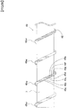
- FIG. 2 is an explanatory diagram of the inside of section A in FIG. 1
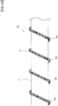
- FIG. 3 is an enlarged view of the shaft for an in vivo recovery mechanism according to the first embodiment.
- the in vivo recovery mechanism 1 of the present invention for removing a substance from a body lumen includes a catheter 3 having a long hollow tubular body, a cutter assembly 4 connected to the distal end of the catheter 3, a grip part 6 connected to the proximal end of the catheter 3, and a motor 8 connected to the proximal end of the grip part 6.
- the cutter assembly 4 includes a plurality of openings 41, a casing 43 connected to the distal end of the catheter 3, and a cutter 2 disposed inside the casing 43.
- the cutter 2 is connected to the distal end of the shaft 10 for an in vivo recovery mechanism described below (see FIG. 2 ), and is capable of rotating with the rotation of the motor 8.
- the cutter assembly 4 cuts a substance in the body D (see FIG. 2 ), such as plaque, that has entered from the openings 41 of the casing 43 by means of the rotating cutter 2, and then takes the substance into the interior of the cutter assembly 4.
- the grip part 6 is connected to the proximal end of the catheter 3, and includes a grip part main body 6a, and a grip part side body 6b, which is letter U-shaped and is connected to the grip part main body 6a. Furthermore, a gap S, which is can be gripped by the person performing the procedure, is formed in the grip part 6 by the grip part main body 6a and the grip part side body 6b.
- the casing of the motor 8 is connected to the proximal end of the grip part 6, and the rotation shaft of the motor 8 is connected to the proximal end of the shaft 10 for an in vivo recovery mechanism described below (see FIG. 2 ).
- the cutter assembly 4 is linearly connected to the catheter 3, and although the mechanism is not shown, in reality the cutter assembly 4 is capable of being bent by an operation of the grip part 6 in all 360 degrees with respect to the long axis of the catheter 3.
- the catheter 3 includes a catheter main body 3b, a bearing 3a connected to the interior of the distal end of the catheter main body 3b, and a bearing (not shown) connected to the interior of the proximal end of the catheter main body 3b. Furthermore, the catheter 3 has the distal end connected to the cutter assembly 4, the proximal end connected to the grip part 6, and the interior is provided with the rotatable shaft 10 for an in vivo recovery mechanism.
- the shaft 10 for an in vivo recovery mechanism is constituted by a shaft 7 and a side wire 5 sparsely wound onto the outer circumference of the shaft 7, and is capable of rotating inside the catheter 3 with the rotation of the motor 8.
- the shaft 7 is formed from a single long metallic wire, and is connected to the proximal end of the cutter 2 through the bearing 3a, which is connected to the interior of the distal end of the catheter 3.
- the material of the shaft 7 is not particularly limited if it is a biocompatible material such as stainless steel, Ni-Ti alloy, or cobalt alloy, stainless steel is used in the present embodiment.
- the shaft 7 may be formed from a long solid metal wire, or may be formed from a long hollow metal wire.
- the shaft 10 for an in vivo recovery mechanism can be made softer by forming the shaft 7 with a long hollow metallic wire, and by inserting a guide wire or the like into a void inside the hollow shaft and causing the hollow shaft to be positioned along the guide wire, the shaft 10 for an in vivo recovery mechanism is capable of reaching the periphery of a body lumen such as a blood vessel.
- Fine protruding and recessed parts 5w are formed on the outer circumferential surface of the side wire 5, and the area in which the protruding and recessed parts 5w are formed is indicated by a hatching pattern in FIG. 2 and FIG. 3 . That is to say, the protruding and recessed parts 5w in the present embodiment are formed on the entire outer circumferential surface of the side wire 5.
- the protruding and recessed parts 5w are formed on the entire outer circumferential surface of the side wire 5, they may be formed on part of the outer circumferential surface of the side wire 5. However, when the protruding and recessed parts 5w are formed on the entire outer circumferential surface of the side wire 5, it is possible to improve the retention performance of the substance in the body and improve the recovery and transport performance to a greater extent.
- the material of the side wire 5 is not particularly limited if it is a biocompatible material such as stainless steel, tungsten, or Ni-Ti alloy, stainless steel is used in the present embodiment.
- the substance in the body D such as plaque, which is cut by the cutter 2 and taken into the interior of the cutter assembly 4, is retained inside the gap G, and is transported in the X direction by the rotation of the shaft 10 for an in vivo recovery mechanism.
- the shaft 10 for an in vivo recovery mechanism is provided with the shaft 7, and the side wire 5 sparsely wound onto the outer circumference of the shaft 7 and having protruding and recessed parts 5w on the outer circumferential surface thereof, and therefore, when rotating the shaft 10 for an in vivo recovery mechanism, the substance in the body D is caught between the sparsely wound side wire 5 on the shaft 7 and held by the protruding and recessed parts 5w formed on the side wire 5, and the performance for recovering and transporting the substance in the body can be improved.
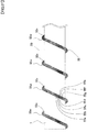
- FIG. 4 is an enlarged view of a shaft for an in vivo recovery mechanism according to the second embodiment.
- the in vivo recovery mechanism used in the shaft for an in vivo recovery mechanism of the present embodiment is identical to that of the shaft for an in vivo recovery mechanism 1 of the first embodiment, and the interior of the distal end of the in vivo recovery mechanism 1 is identical to FIG. 2 , and therefore, the description thereof will be omitted, and further, those parts that are the same as the first embodiment will be referred to by the same reference numerals, and the description will be omitted.
- the shaft 20 for an in vivo recovery mechanism of the present embodiment has the distal end connected to the cutter 2 through the bearing 3a connected to the interior of the distal end of the catheter main body 3b, the proximal end connected to the motor 8 through a bearing (not shown) connected to the interior of the proximal end of the catheter main body 3b, and is capable of rotating with the rotation of the motor 8.
- the shaft 20 for an in vivo recovery mechanism is constituted by the shaft 7 and a strand 25 (corresponding to a "first strand” of the present invention) serving as the side wire sparsely wound onto the outer circumference of the shaft 7, and the strand 25 is formed by twisting seven wires (corresponding to "first wires" of the present invention) 25a, 25b, 25c, 25d, 25e, 25f, and 25g.
- twisting direction of the strand 25 is a counterclockwise direction (hereinafter, referred to as "S-twisting") toward the left direction in the drawing
- winding direction of the strand 25 onto the shaft 7 is a clockwise winding (hereinafter, referred to as "Z-winding") toward the left direction of the drawing, such that the twisting direction of the strand 25 and the winding direction of the strand 25 onto the shaft 7 are opposite directions.
- Protruding and recessed parts 25w are formed from the outline of the strand 25, and the protruding and recessed parts 25w are formed around the entire outer circumferential surface of the strand 25.
- the material of the wires (corresponding to "first wires" of the present invention) 25a, 25b, 25c, 25d, 25e, 25f, and 25g constituting the strand 25 is not particularly limited if it is a biocompatible material such as stainless steel, tungsten, or Ni-Ti alloy, stainless steel is used in the present embodiment.
- the shaft 20 for an in vivo recovery mechanism is provided with the shaft 7, and the strand 25 sparsely wound onto the outer circumference of the shaft 7 and having protruding and recessed parts 25w on the outer circumferential surface thereof, and therefore, the protruding and recessed parts 25w of the strand 25 can be easily formed, and when rotating the shaft 20 for an in vivo recovery mechanism, the substance in the body D is caught between the sparsely wound strand 25 on the shaft 7 and held by the protruding and recessed parts 25w formed from the outline of the strand 25, and the performance for recovering and transporting the substance in the body can be improved.
- the strand 25 (corresponding to the "first strand" of the present invention) serving as the side wire is a strand consisting of seven wires, however the number of wires is not limited to seven, and may be a strand consisting of any number of two or more wires which enables a strand to be formed. However, from the viewpoint of the effect of the protruding and recessed parts 25W of the present embodiment, it is better to form the strand using the largest possible number of wires.
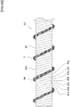
- FIG. 5 is an enlarged view of a shaft for an in vivo recovery mechanism according to the third embodiment.
- the in vivo recovery mechanism used in the shaft for an in vivo recovery mechanism of the present embodiment is identical to that of the shaft for an in vivo recovery mechanism 1 of the first embodiment, and the interior of the distal end of the in vivo recovery mechanism 1 is identical to FIG. 2 , and therefore, the description thereof will be omitted, and further, those parts that are the same as the first embodiment will be referred to by the same reference numerals, and the description will be omitted.
- the shaft 30 for an in vivo recovery mechanism of the present embodiment has the distal end connected to the cutter 2 through the bearing 3a connected to the interior of the distal end of the catheter main body 3b, the proximal end connected to the motor 8 through a bearing (not shown) connected to the interior of the proximal end of the catheter main body 3b, and is capable of rotating with the rotation of the motor 8.
- the shaft 30 for an in vivo recovery mechanism is constituted by the shaft 7 and a strand 35 (corresponding to a "first strand” of the present invention) serving as the side wire sparsely wound onto the outer circumference of the shaft 7, and the strand 35 is formed by twisting seven wires (corresponding to "first wires" of the present invention) 35a, 35b, 35c, 35d, 35e, 35f, and 35g.
- twisting direction of the strand 35 is a clockwise direction (hereinafter, referred to as "Z-twisting") toward the left direction of the drawing
- winding direction of the strand 35 onto the shaft 7 is a Z-winding, such that the twisting direction of the strand 35 and the winding direction of the strand 35 onto the shaft 7 are the same direction.
- protruding and recessed parts 35w are formed from the outline of the strand 35, and the protruding and recessed parts 35w are formed around the entire outer circumferential surface of the strand 35.
- the protruding and recessed parts 35w have protruding parts and recessed parts, which are perpendicularly inclined in a direction parallel to the long axis direction of the shaft 7.
- the material of the wires (corresponding to "first wires" of the present invention) 35a, 35b, 35c, 35d, 35e, 35f, and 35g constituting the strand 35 is not particularly limited if it is a biocompatible material such as stainless steel, tungsten, or Ni-Ti alloy, stainless steel is used in the present embodiment.
- the twisting direction of the strand 35 serving as the side wire and the winding direction of the strand 35 onto the shaft 7 are the same direction, and therefore, the protruding and recessed parts 35w have protruding parts and recessed parts which are perpendicularly inclined in a direction parallel to the long axis of the shaft 7, and when rotating the shaft 30 for an in vivo recovery mechanism, the performance for recovering and transporting the substance in the body can be further improved.
- the strand 35 (corresponding to a "first strand" of the present invention) serving as the side wire is a strand consisting of seven wires, however the number of wires is not limited to seven, and may be a strand consisting of any number of two or more wires which enables a strand to be formed. However, from the viewpoint of the effect of the protruding and recessed parts 35W of the present embodiment, it is better to form the strand using the largest possible number of wires.
- FIG. 6 is an enlarged view of a shaft for an in vivo recovery mechanism according to the fourth embodiment.
- the in vivo recovery mechanism used in the shaft for an in vivo recovery mechanism of the present embodiment is identical to that of the shaft for an in vivo recovery mechanism 1 of the first embodiment, and the interior of the distal end of the in vivo recovery mechanism 1 is identical to FIG. 2 , and therefore, the description thereof will be omitted, and further, those parts that are the same as the first embodiment will be referred to by the same reference numerals, and the description will be omitted.
- the shaft 40 for an in vivo recovery mechanism of the present embodiment has the distal end connected to the cutter 2 through the bearing 3a connected to the interior of the distal end of the catheter main body 3b, the proximal end connected to the motor 8 through a bearing (not shown) connected to the interior of the proximal end of the catheter main body 3b, and is capable of rotating with the rotation of the motor 8.
- the shaft 40 for an in vivo recovery mechanism includes the shaft 7 and a strand 45 (corresponding to a "first strand” of the present invention) serving as the side wire sparsely wound onto the outer circumference of the shaft 7, and the strand 45 is formed by twisting seven wires (corresponding to "first wires" of the present invention) 45a, 45b, 45c, 45d, 45e, 45f, and 45g.
- twisting direction of the strand 45 is a Z-twisting
- winding direction of the strand 45 onto the shaft 7 is a Z-winding, such that the twisting direction of the strand 45 and the winding direction of the strand 45 onto the shaft 7 are the same direction.
- protruding and recessed parts 45w are formed from the outline of the strand 45, and the protruding and recessed parts 45w are formed around the entire outer circumferential surface of the strand 45.
- the protruding and recessed parts 45w have protruding parts and recessed parts, which extend along a direction substantially perpendicular to the long axis direction of the shaft 7, in a direction parallel to the long axis direction.
- the material of the wires (corresponding to "first wires" of the present invention) 45a, 45b, 45c, 45d, 45e, 45f, and 45g constituting the strand 45 is not particularly limited if it is a biocompatible material such as stainless steel, tungsten, or Ni-Ti alloy, stainless steel is used in the present embodiment.
- the protruding and recessed parts 45w have protruding parts and recessed parts, which extend along a direction substantially perpendicular to a long axis direction of the shaft 7, in a direction parallel to the long axis direction, and therefore, when the shaft 40 for an in vivo recovery mechanism is rotated, the performance for recovering and transporting the substance in the body can be further improved.
- the strand 45 (corresponding to a "first strand" of the present invention) serving as the side wire is a strand consisting of seven wires, however the number of wires is not limited to seven, and may be a strand consisting of any number of two or more wires which enables a strand to be formed. However, from the viewpoint of the effect of the protruding and recessed parts 45W of the present embodiment, it is better to form the strand using the largest possible number of wires.
- protruding and recessed parts 45w are formed from the outline of the strand 45 serving as the side wire, by application to the shaft 10 for an in vivo recovery mechanism of the first embodiment, protruding parts and recessed parts may be formed on the outer circumferential surface of the side wire 5 so as to extend along a direction substantially perpendicular to the long axis direction of the shaft 7, in a direction parallel to the long axis direction.
- FIG. 7 is an enlarged view of a shaft for an in vivo recovery mechanism according to the fifth embodiment.
- the in vivo recovery mechanism used in the shaft for an in vivo recovery mechanism of the present embodiment is identical to that of the shaft for an in vivo recovery mechanism 1 of the first embodiment, and the interior of the distal end of the in vivo recovery mechanism 1 is identical to FIG. 2 , and therefore, the description thereof will be omitted, and further, those parts that are the same as the first embodiment will be referred to by the same reference numerals, and the description will be omitted.
- the shaft 50 for an in vivo recovery mechanism of the present embodiment has the distal end connected to the cutter 2 through the bearing 3a connected to the interior of the distal end of the catheter main body 3b, and the proximal end connected to the motor 8 through a bearing (not shown) connected to the interior of the proximal end of the catheter main body 3b, and is capable of rotating with the rotation of the motor 8.
- the shaft 50 for an in vivo recovery mechanism is constituted by the shaft 7 and a strand 55 (corresponding to a "first strand” of the present invention) serving as the side wire sparsely wound onto the outer circumference of the shaft 7, and the strand 55 is formed by twisting seven wires (corresponding to "first wires" of the present invention) 55a, 55b, 55c, 55d, 55e, 55f, and 55g.
- the twisting direction of the strand 55 is a Z-twisting
- the winding direction of the strand 55 onto the shaft 7 is a counterclockwise winding (hereinafter, referred to as "S-winding") toward the left direction of the drawing, such that the twisting direction of the strand 55 and the winding direction of the strand 55 onto the shaft 7 are opposite directions.
- protruding and recessed parts 55w are formed from the outline of the strand 55, and fine protruding and recessed parts 55x are formed on the outer circumferential surface of the wires (corresponding to the "first wires" of the present invention) 55a, 55b, 55c, 55d, 55e, 55f, and 55g constituting the strand 55.
- the area in which the protruding and recessed parts 55x are formed is indicated by a hatching pattern in FIG. 7 . That is to say, the protruding and recessed parts 55x in the present embodiment are formed on the entire outer circumferential surface of the wires 55a, 55b, 55c, 55d, 55e, 55f, and 55g.
- the protruding and recessed parts 55x are formed on the entire outer circumferential surface of the wires 55a, 55b, 55c, 55d, 55e, 55f, and 55g, however they may be formed on part of the outer circumferential surface of the wires, and further, they may be formed on the entire outer circumferential surface of some of the wires and not formed at all on the outer circumferential surface of the other wires.
- the protruding and recessed parts 55x are formed on the entire outer circumferential surface of the wires 55a, 55b, 55c, 55d, 55e, 55f, and 55g, it is possible to improve the retention performance of the substance in the body and improve the recovery and transport performance to a greater extent.
- the material of the wires (corresponding to "first wires" of the present invention) 55a, 55b, 55c, 55d, 55e, 55f, and 55g constituting the strand 55 is not particularly limited if it is a biocompatible material such as stainless steel, tungsten, or Ni-Ti alloy, stainless steel is used in the present embodiment.
- the protruding and recessed parts 55w are formed from the outline of the strand 55, and the protruding and recessed parts 55x are formed on the outer circumferential surface of the wires 55a, 55b, 55c, 55d, 55e, 55f, and 55g constituting the strand 55, and therefore, the performance for recovering and transporting the substance in the body can be further improved.
- the strand 55 (corresponding to a "first strand" of the present invention) serving as the side wire is a strand consisting of seven wires, however the number of wires is not limited to seven, and may be a strand consisting of any number of two or more wires which enables a strand to be formed. However, from the viewpoint of the effect of the protruding and recessed parts 55W of the present embodiment, it is better to form the strand using the largest possible number of wires.
- FIG. 8 is an enlarged view of a shaft for an in vivo recovery mechanism according to the sixth embodiment.
- the in vivo recovery mechanism used in the shaft for an in vivo recovery mechanism of the present embodiment is identical to that of the shaft for an in vivo recovery mechanism 1 of the first embodiment, and the interior of the distal end of the in vivo recovery mechanism 1 is identical to FIG. 2 , and therefore, the description thereof will be omitted, and further, those parts that are the same as the first embodiment will be referred to by the same reference numerals, and the description will be omitted.
- the shaft 60 for an in vivo recovery mechanism of the present embodiment has the distal end connected to the cutter 2 through the bearing 3a connected to the interior of the distal end of the catheter main body 3b, and the proximal end connected to the motor 8 through a bearing (not shown) connected to the interior of the proximal end of the catheter main body 3b, and is capable of rotating with the rotation of the motor 8.
- the shaft 60 for an in vivo recovery mechanism includes a strand 67, which is a shaft formed by twisting seven wires (corresponding to "second wires" of the present invention) 67a, 67b, 67c, 67d, 67e, 67f, and 67g, and the side wire 5 sparsely wound onto the outer circumference of the strand 67.
- a strand 67 which is a shaft formed by twisting seven wires (corresponding to "second wires" of the present invention) 67a, 67b, 67c, 67d, 67e, 67f, and 67g, and the side wire 5 sparsely wound onto the outer circumference of the strand 67.
- twisting direction of the strand 67 is a Z-twisting
- winding direction of the side wire 5 onto the shaft 7 is a Z-winding, such that the twisting direction of the strand 67 and the winding direction of the side wire 5 onto the shaft 67 are the same direction.
- protruding and recessed parts 67w are formed from the outline of the strand 67.
- the material of the wires (corresponding to "second wires" of the present invention) 67a, 67b, 67c, 67d, 67e, 67f, and 67g constituting the strand 67 is not particularly limited if it is a biocompatible material such as stainless steel, tungsten, or Ni-Ti alloy, stainless steel is used in the present embodiment.
- the shaft 60 for an in vivo recovery mechanism of the present embodiment is constituted by a strand 67 (corresponding to a "second strand" of the present invention) formed by twisting a plurality of wires 67a, 67b, 67c, 67d, 67e, 67f, and 67g, and therefore, the shaft 60 for an in vivo recovery mechanism is made softer, and further, when rotating the shaft 60 for an in vivo recovery mechanism, the substance in the body D is caught between the sparsely wound side wire 5 on the strand 67 and held by the protruding and recessed parts 67w formed from the strand 67 and the protruding and recessed parts 5w formed on the side wire 5, and the performance for recovering and transporting the substance in the body can be further improved.
- the strand 67 (corresponding to a "second strand" of the present invention) serving as the shaft is a strand consisting of seven wires, however the number of wires is not limited to seven, and may be a strand consisting of any number of two or more wires which enables a strand to be formed. However, from the viewpoint of the effect of the protruding and recessed parts 67W of the present embodiment, it is better to form the strand using the largest possible number of wires.
- the present embodiment was described by applying the side wire 5 of the first embodiment to the side wire, but the strand 25 of the second embodiment, the strand 35 of the third embodiment, the strand 45 of the fourth embodiment, and the strand 55 of the fifth embodiment may be applied instead of the side wire 5 sparsely wound onto the outer circumference of the strand 67 of the present embodiment, and in those cases, the effects of each alternative side wire described in the respective embodiments are provided in addition to the effects of the strand 67.
- FIG. 9 is an enlarged view of a shaft for an in vivo recovery mechanism according to the seventh embodiment.
- the in vivo recovery mechanism used in the shaft for an in vivo recovery mechanism of the present embodiment is identical to that of the shaft for an in vivo recovery mechanism 1 of the first embodiment, and the interior of the distal end of the in vivo recovery mechanism 1 is identical to FIG. 2 , and therefore, the description thereof will be omitted, and further, those parts that are the same as the first embodiment will be referred to by the same reference numerals, and the description will be omitted.
- the shaft 70 for an in vivo recovery mechanism of the present embodiment has the distal end connected to the cutter 2 through the bearing 3a connected to the interior of the distal end of the catheter main body 3b, the proximal end connected to the motor 8 through a bearing (not shown) connected to the interior of the proximal end of the catheter main body 3b, and is capable of rotating with the rotation of the motor 8.
- the shaft 70 for an in vivo recovery mechanism includes a hollow strand 77, which is a hollow shaft formed by twisting six wires (corresponding to "third wires" of the present invention) 77a, 77b, 77c, 77d, 77e, and 77f, and the strand 45 sparsely wound onto the outer circumference of the hollow strand 77.
- twisting direction of the hollow strand 77 is a Z-twisting
- winding direction of the strand 45 onto the hollow strand 77 is a Z-winding, such that the twisting direction of the hollow strand 77 and the winding direction of the strand 45 onto the hollow strand 77 are the same direction.
- protruding and recessed parts 77w are formed from the outline of the hollow strand 77.
- the material of the wires (corresponding to "third wires" of the present invention) 77a, 77b, 77c, 77d, 77e, and 77f, constituting the hollow strand 77 is not particularly limited if it is a biocompatible material such as stainless steel, tungsten, or Ni-Ti alloy, stainless steel is used in the present embodiment.
- the shaft 70 for an in vivo recovery mechanism of the present embodiment is constituted by the hollow strand 77 formed by twisting the plurality of wires (corresponding to "third wires" of the present invention) 77a, 77b, 77c, 77d, 77e, and 77f, and therefore, the shaft 70 for an in vivo recovery mechanism is made softer, and further, when rotating the shaft 70 for an in vivo recovery mechanism, the substance in the body D is caught between the sparsely wound strand 45 on the hollow strand 77 and held by the protruding and recessed parts 77w formed from the hollow strand 77 and the protruding and recessed parts 45w formed on the side wire, and the performance for recovering and transporting the substance in the body can be further improved.
- the shaft 70 for an in vivo recovery mechanism is capable of reaching the periphery of a body lumen such as a blood vessel.
- the hollow strand 77 serving as the shaft is a strand consisting of seven wires, however the number of wires is not limited to seven, and may be a strand consisting of any number of two or more wires which enables a strand to be formed. However, from the viewpoint of the effect of the protruding and recessed parts 77W of the present embodiment, it is better to form the strand using the largest possible number of wires.
- the present embodiment was described by applying the strand 45 of the fourth embodiment to the side wire, but the side wire 5 of the first embodiment, the strand 25 of the second embodiment, the strand 35 of the third embodiment, and the strand 55 of the fifth embodiment may be applied instead of the strand 45 sparsely wound onto the outer circumference of the strand 77 of the present embodiment, and in those cases, the effects of each alternative side wire described in the respective embodiments are provided in addition to the effects of the strand 77.
Landscapes
- Health & Medical Sciences (AREA)
- Surgery (AREA)
- Life Sciences & Earth Sciences (AREA)
- Medical Informatics (AREA)
- Nuclear Medicine, Radiotherapy & Molecular Imaging (AREA)
- Engineering & Computer Science (AREA)
- Biomedical Technology (AREA)
- Heart & Thoracic Surgery (AREA)
- Vascular Medicine (AREA)
- Molecular Biology (AREA)
- Animal Behavior & Ethology (AREA)
- General Health & Medical Sciences (AREA)
- Public Health (AREA)
- Veterinary Medicine (AREA)
- Orthopedic Medicine & Surgery (AREA)
- Surgical Instruments (AREA)
Abstract
Description
- The present invention relates to a shaft for an in vivo recovery mechanism for use in an in vivo recovery mechanism that removes a substance from a body lumen.
- Conventionally, various devices have been developed that remove a substance from a body lumen of a patient. For example, in
Patent Document 1, a device for removing a substance from a body lumen is described which includes a catheter having a proximal end, a distal end, and a catheter lumen that extends therethrough, a cutter assembly which is rotatably joined to the distal end of the catheter, and a rotatable torque shaft having a first end, which extends through the catheter lumen and is joined to the cutter assembly, and a second end which is configured so as to be joined to a rotation mechanism, wherein an outer coil is provided on an outer surface of the torque shaft, and the outer coil is spirally formed on the outer surface of the torque shaft such that a substance inside a body lumen is transported in the proximal direction when the torque shaft is rotated (see FIG. 20, etc.). - Patent Document 1: Japanese Unexamined Patent Application Publication No.
2013-138877 - The device described in Patent Document 1 (hereinafter referred to as "in vivo recovery mechanism") discharges a substance inside a body lumen (hereinafter referred to as "substance in the body") to the outside of a patient's body by means of the outer coil spirally formed on the torque shaft, and the performance for recovering and transporting the substance in the body depends on the outer coil.
- Furthermore, in procedures and surgeries, it is vital to quickly perform the work of recovering and transporting the substance in the body, and enhancements that enable the recovery and transport performance to be further improved are desired.
- The present invention has been made in response to the above problems associated with the conventional technique, and an object of the present invention is to provide a shaft for an in vivo recovery mechanism that improves the recovery and transport performance of an in vivo recovery mechanism to enable in vivo recovery work in procedures and surgeries to be quickly and reliably performed.
- In order to solve the above problems, a shaft for an in vivo recovery mechanism according to a first aspect of the present invention includes a shaft, and a side wire sparsely wound onto an outer circumference of the shaft, and having protruding and recessed parts on an outer circumferential surface thereof.
- Furthermore, a second aspect of the present invention is the shaft for an in vivo recovery mechanism according to the first aspect, wherein the side wire is constituted by a first strand formed by twisting a plurality of first wires, and the protruding and recessed parts of the side wire are formed from an outline of the first strand.
- Moreover, a third aspect of the present invention is the shaft for an in vivo recovery mechanism according to the second aspect, wherein a twisting direction of the first strand is the same direction as a winding direction of the side wire onto the shaft.
- Also, a fourth aspect of the present invention is the shaft for an in vivo recovery mechanism according to the second aspect or the third aspect, wherein protruding and recessed parts are formed on an outer circumferential surface of the wires constituting the first strand.
- In addition, a fifth aspect of the present invention is the shaft for an in vivo recovery mechanism according to any one of the first aspect to the fourth aspect, wherein the protruding and recessed parts have protruding parts and recessed parts, which extend along a direction substantially perpendicular to a long axis direction of the shaft, in a direction parallel to the long axis direction.
- Moreover, a sixth aspect of the present invention is the shaft for an in vivo recovery mechanism according to any one of the first aspect to the fifth aspect, wherein the shaft is constituted by a second strand formed by twisting a plurality of second wires.
- Further, a seventh aspect of the present invention is the shaft for an in vivo recovery mechanism of any one of the first aspect to the fifth aspect, wherein the shaft is constituted by a hollow strand formed by twisting a plurality of third wires.
- The shaft for an in vivo recovery mechanism according to the first aspect of the present invention is provided with a shaft, and a side wire sparsely wound onto the outer circumference of the shaft and having protruding and recessed parts on the outer circumferential surface thereof, and therefore, when rotating the shaft for an in vivo recovery mechanism, a substance in the body is caught between the sparsely wound side wire on the shaft and held by the protruding and recessed parts formed on the side wire, and the performance for recovering and transporting the substance in the body can be improved.
- Furthermore, the second aspect of the present invention is the shaft for an in vivo recovery mechanism according to the first aspect, wherein the side wire is constituted by a first strand formed by twisting a plurality of first wires, and the protruding and recessed parts of the side wire are formed from an outline of the first strand, and therefore, the protruding and recessed parts of the side wire are easily formed, and when rotating the shaft for an in vivo recovery mechanism, a substance in the body is caught between the sparsely wound side wire on the shaft and held by the protruding and recessed parts formed from the outline of the first strand, and the performance for recovering and transporting the substance in the body can be improved.
- Moreover, the third aspect of the present invention is the shaft for an in vivo recovery mechanism according to the second aspect, wherein a twisting direction of the first strand is the same direction as a winding direction of the side wire onto the shaft, and therefore, the protruding and recessed parts have protruding parts and recessed parts, which are perpendicularly inclined in a direction parallel to the long axis of the shaft, and when rotating the shaft for an in vivo recovery mechanism, in addition to the effects of the shaft for an in vivo recovery mechanism of the second aspect, the performance for recovering and transporting the substance in the body can be further improved.
- Also, the fourth aspect of the present invention is the shaft for an in vivo recovery mechanism according to the second aspect or the third aspect, wherein protruding and recessed parts are formed on an outer circumferential surface of the wires constituting the first strand, and therefore, in addition to the effects of the shaft for an in vivo recovery mechanism of the second aspect or the third aspect, the performance for recovering and transporting the substance in the body can be further improved.
- In addition, the fifth aspect of the present invention is the shaft for an in vivo recovery mechanism according to any one of the first aspect to the fourth aspect, wherein the protruding and recessed parts have protruding parts and recessed parts, which extend along a direction substantially perpendicular to a long axis direction of a hollow shaft, in a direction parallel to the long axis direction, and therefore, when rotating the shaft for an in vivo recovery mechanism, in addition to the effects of the shaft for an in vivo recovery mechanism of any one of the first aspect to the fourth aspect, the performance for recovering and transporting the substance in the body can be further improved.
- Furthermore, the sixth aspect of the present invention is the shaft for an in vivo recovery mechanism according to any one of the first aspect to the fifth aspect, wherein the shaft is constituted by a second strand formed by twisting a plurality of second wires, and therefore, in addition to the effects of the shaft for an in vivo recovery mechanism of any one of the first aspect to the fifth aspect, the shaft for an in vivo recovery mechanism is made softer, and further, when rotating the shaft for an in vivo recovery mechanism, the substance in the body is caught between the sparsely wound side wire on the shaft and held by the protruding and recessed parts formed from the second strand of the shaft and the protruding and recessed parts formed on the side wire, and the performance for recovering and transporting the substance in the body can be further improved.
- In addition, the seventh aspect of the present invention is the shaft for an in vivo recovery mechanism according to any one of the first aspect to the fifth aspect, wherein the shaft is constituted by a hollow strand formed by twisting a plurality of third wires, and therefore, in addition to the effects of the shaft for an in vivo recovery mechanism of any one of the first aspect to the fifth aspect, the shaft for an in vivo recovery mechanism is made even softer, and further, when rotating the shaft for an in vivo recovery mechanism, the substance in the body is caught between the sparsely wound side wire on the shaft and held by the protruding and recessed parts formed from the hollow strand of the shaft and the protruding and recessed parts formed on the side wire, and the performance for recovering and transporting the substance in the body can be further improved. Furthermore, by inserting a guide wire or the like into a void inside the hollow strand and causing the hollow strand to be positioned along the guide wire, the shaft for an in vivo recovery mechanism is capable of reaching the periphery of a body lumen such as a blood vessel.
-
-
FIG. 1 is an external view of an in vivo recovery mechanism using a shaft for an in vivo recovery mechanism according to a first embodiment of the present invention. -
FIG. 2 is an explanatory diagram of the inside of section A inFIG. 1 . -
FIG. 3 is an enlarged view of the shaft for an in vivo recovery mechanism of the first embodiment. -
FIG. 4 is an enlarged view of a shaft for an in vivo recovery mechanism according to a second embodiment. -
FIG. 5 is an enlarged view of a shaft for an in vivo recovery mechanism according to a third embodiment. -
FIG. 6 is an enlarged view of a shaft for an in vivo recovery mechanism according to a fourth embodiment. -
FIG. 7 is an enlarged view of a shaft for an in vivo recovery mechanism according to a fifth embodiment. -
FIG. 8 is an enlarged view of a shaft for an in vivo recovery mechanism according to a sixth embodiment. -
FIG. 9 is an enlarged view of a shaft for an in vivo recovery mechanism according to a seventh embodiment. - Hereinafter, embodiments of the present invention will be described with reference to the drawings.
- First, a first embodiment of the present invention will be described.
-
FIG. 1 is an external view of an in vivo recovery mechanism using a shaft for an in vivo recovery mechanism according to the first embodiment of the present invention,FIG. 2 is an explanatory diagram of the inside of section A inFIG. 1 , andFIG. 3 is an enlarged view of the shaft for an in vivo recovery mechanism according to the first embodiment. - As shown in
FIG. 1 , the invivo recovery mechanism 1 of the present invention for removing a substance from a body lumen includes acatheter 3 having a long hollow tubular body, acutter assembly 4 connected to the distal end of thecatheter 3, agrip part 6 connected to the proximal end of thecatheter 3, and amotor 8 connected to the proximal end of thegrip part 6. - The
cutter assembly 4 includes a plurality ofopenings 41, acasing 43 connected to the distal end of thecatheter 3, and acutter 2 disposed inside thecasing 43. Thecutter 2 is connected to the distal end of theshaft 10 for an in vivo recovery mechanism described below (seeFIG. 2 ), and is capable of rotating with the rotation of themotor 8. - Therefore, the
cutter assembly 4 cuts a substance in the body D (seeFIG. 2 ), such as plaque, that has entered from theopenings 41 of thecasing 43 by means of the rotatingcutter 2, and then takes the substance into the interior of thecutter assembly 4. - The
grip part 6 is connected to the proximal end of thecatheter 3, and includes a grip partmain body 6a, and a grippart side body 6b, which is letter U-shaped and is connected to the grip partmain body 6a. Furthermore, a gap S, which is can be gripped by the person performing the procedure, is formed in thegrip part 6 by the grip partmain body 6a and the grippart side body 6b. - Moreover, the casing of the
motor 8 is connected to the proximal end of thegrip part 6, and the rotation shaft of themotor 8 is connected to the proximal end of theshaft 10 for an in vivo recovery mechanism described below (seeFIG. 2 ). - In
FIG. 1 , thecutter assembly 4 is linearly connected to thecatheter 3, and although the mechanism is not shown, in reality thecutter assembly 4 is capable of being bent by an operation of thegrip part 6 in all 360 degrees with respect to the long axis of thecatheter 3. - The
catheter 3 includes a cathetermain body 3b, abearing 3a connected to the interior of the distal end of the cathetermain body 3b, and a bearing (not shown) connected to the interior of the proximal end of the cathetermain body 3b. Furthermore, thecatheter 3 has the distal end connected to thecutter assembly 4, the proximal end connected to thegrip part 6, and the interior is provided with therotatable shaft 10 for an in vivo recovery mechanism. - As shown in
FIG. 2 , theshaft 10 for an in vivo recovery mechanism is constituted by ashaft 7 and aside wire 5 sparsely wound onto the outer circumference of theshaft 7, and is capable of rotating inside thecatheter 3 with the rotation of themotor 8. - The
shaft 7 is formed from a single long metallic wire, and is connected to the proximal end of thecutter 2 through thebearing 3a, which is connected to the interior of the distal end of thecatheter 3. Although the material of theshaft 7 is not particularly limited if it is a biocompatible material such as stainless steel, Ni-Ti alloy, or cobalt alloy, stainless steel is used in the present embodiment. - The
shaft 7 may be formed from a long solid metal wire, or may be formed from a long hollow metal wire. However, theshaft 10 for an in vivo recovery mechanism can be made softer by forming theshaft 7 with a long hollow metallic wire, and by inserting a guide wire or the like into a void inside the hollow shaft and causing the hollow shaft to be positioned along the guide wire, theshaft 10 for an in vivo recovery mechanism is capable of reaching the periphery of a body lumen such as a blood vessel. - Fine protruding and recessed
parts 5w are formed on the outer circumferential surface of theside wire 5, and the area in which the protruding and recessedparts 5w are formed is indicated by a hatching pattern inFIG. 2 andFIG. 3 . That is to say, the protruding and recessedparts 5w in the present embodiment are formed on the entire outer circumferential surface of theside wire 5. - In the present embodiment, although the protruding and recessed
parts 5w are formed on the entire outer circumferential surface of theside wire 5, they may be formed on part of the outer circumferential surface of theside wire 5. However, when the protruding and recessedparts 5w are formed on the entire outer circumferential surface of theside wire 5, it is possible to improve the retention performance of the substance in the body and improve the recovery and transport performance to a greater extent. - Furthermore, although the material of the
side wire 5 is not particularly limited if it is a biocompatible material such as stainless steel, tungsten, or Ni-Ti alloy, stainless steel is used in the present embodiment. - Moreover, because a gap G is formed between the
catheter 3 and theshaft 10 for an in vivo recovery mechanism, the substance in the body D, such as plaque, which is cut by thecutter 2 and taken into the interior of thecutter assembly 4, is retained inside the gap G, and is transported in the X direction by the rotation of theshaft 10 for an in vivo recovery mechanism. - The
shaft 10 for an in vivo recovery mechanism is provided with theshaft 7, and theside wire 5 sparsely wound onto the outer circumference of theshaft 7 and having protruding and recessedparts 5w on the outer circumferential surface thereof, and therefore, when rotating theshaft 10 for an in vivo recovery mechanism, the substance in the body D is caught between the sparselywound side wire 5 on theshaft 7 and held by the protruding and recessedparts 5w formed on theside wire 5, and the performance for recovering and transporting the substance in the body can be improved. - Next, a second embodiment of the present invention will be described.
-
FIG. 4 is an enlarged view of a shaft for an in vivo recovery mechanism according to the second embodiment. - Hereinafter, the second embodiment of the present invention will be described, however, the in vivo recovery mechanism used in the shaft for an in vivo recovery mechanism of the present embodiment is identical to that of the shaft for an in
vivo recovery mechanism 1 of the first embodiment, and the interior of the distal end of the invivo recovery mechanism 1 is identical toFIG. 2 , and therefore, the description thereof will be omitted, and further, those parts that are the same as the first embodiment will be referred to by the same reference numerals, and the description will be omitted. - The
shaft 20 for an in vivo recovery mechanism of the present embodiment has the distal end connected to thecutter 2 through thebearing 3a connected to the interior of the distal end of the cathetermain body 3b, the proximal end connected to themotor 8 through a bearing (not shown) connected to the interior of the proximal end of the cathetermain body 3b, and is capable of rotating with the rotation of themotor 8. - As shown in
FIG. 4 , theshaft 20 for an in vivo recovery mechanism is constituted by theshaft 7 and a strand 25 (corresponding to a "first strand" of the present invention) serving as the side wire sparsely wound onto the outer circumference of theshaft 7, and thestrand 25 is formed by twisting seven wires (corresponding to "first wires" of the present invention) 25a, 25b, 25c, 25d, 25e, 25f, and 25g. - Furthermore, the twisting direction of the
strand 25 is a counterclockwise direction (hereinafter, referred to as "S-twisting") toward the left direction in the drawing, and the winding direction of thestrand 25 onto theshaft 7 is a clockwise winding (hereinafter, referred to as "Z-winding") toward the left direction of the drawing, such that the twisting direction of thestrand 25 and the winding direction of thestrand 25 onto theshaft 7 are opposite directions. - Protruding and recessed
parts 25w are formed from the outline of thestrand 25, and the protruding and recessedparts 25w are formed around the entire outer circumferential surface of thestrand 25. - Furthermore, although the material of the wires (corresponding to "first wires" of the present invention) 25a, 25b, 25c, 25d, 25e, 25f, and 25g constituting the
strand 25 is not particularly limited if it is a biocompatible material such as stainless steel, tungsten, or Ni-Ti alloy, stainless steel is used in the present embodiment. - The
shaft 20 for an in vivo recovery mechanism is provided with theshaft 7, and thestrand 25 sparsely wound onto the outer circumference of theshaft 7 and having protruding and recessedparts 25w on the outer circumferential surface thereof, and therefore, the protruding and recessedparts 25w of thestrand 25 can be easily formed, and when rotating theshaft 20 for an in vivo recovery mechanism, the substance in the body D is caught between the sparsely woundstrand 25 on theshaft 7 and held by the protruding and recessedparts 25w formed from the outline of thestrand 25, and the performance for recovering and transporting the substance in the body can be improved. - Note that, in the present embodiment, the strand 25 (corresponding to the "first strand" of the present invention) serving as the side wire is a strand consisting of seven wires, however the number of wires is not limited to seven, and may be a strand consisting of any number of two or more wires which enables a strand to be formed. However, from the viewpoint of the effect of the protruding and recessed parts 25W of the present embodiment, it is better to form the strand using the largest possible number of wires.
- Next, a third embodiment of the present invention will be described.
-
FIG. 5 is an enlarged view of a shaft for an in vivo recovery mechanism according to the third embodiment. - Hereinafter, the third embodiment of the present invention will be described, however, the in vivo recovery mechanism used in the shaft for an in vivo recovery mechanism of the present embodiment is identical to that of the shaft for an in
vivo recovery mechanism 1 of the first embodiment, and the interior of the distal end of the invivo recovery mechanism 1 is identical toFIG. 2 , and therefore, the description thereof will be omitted, and further, those parts that are the same as the first embodiment will be referred to by the same reference numerals, and the description will be omitted. - The
shaft 30 for an in vivo recovery mechanism of the present embodiment has the distal end connected to thecutter 2 through thebearing 3a connected to the interior of the distal end of the cathetermain body 3b, the proximal end connected to themotor 8 through a bearing (not shown) connected to the interior of the proximal end of the cathetermain body 3b, and is capable of rotating with the rotation of themotor 8. - As shown in
FIG. 5 , theshaft 30 for an in vivo recovery mechanism is constituted by theshaft 7 and a strand 35 (corresponding to a "first strand" of the present invention) serving as the side wire sparsely wound onto the outer circumference of theshaft 7, and thestrand 35 is formed by twisting seven wires (corresponding to "first wires" of the present invention) 35a, 35b, 35c, 35d, 35e, 35f, and 35g. - Furthermore, the twisting direction of the
strand 35 is a clockwise direction (hereinafter, referred to as "Z-twisting") toward the left direction of the drawing, and the winding direction of thestrand 35 onto theshaft 7 is a Z-winding, such that the twisting direction of thestrand 35 and the winding direction of thestrand 35 onto theshaft 7 are the same direction. - Moreover, protruding and recessed
parts 35w are formed from the outline of thestrand 35, and the protruding and recessedparts 35w are formed around the entire outer circumferential surface of thestrand 35. In addition, the protruding and recessedparts 35w have protruding parts and recessed parts, which are perpendicularly inclined in a direction parallel to the long axis direction of theshaft 7. - Although the material of the wires (corresponding to "first wires" of the present invention) 35a, 35b, 35c, 35d, 35e, 35f, and 35g constituting the
strand 35 is not particularly limited if it is a biocompatible material such as stainless steel, tungsten, or Ni-Ti alloy, stainless steel is used in the present embodiment. - According to the
shaft 30 for an in vivo recovery mechanism of the present embodiment, the twisting direction of thestrand 35 serving as the side wire and the winding direction of thestrand 35 onto theshaft 7 are the same direction, and therefore, the protruding and recessedparts 35w have protruding parts and recessed parts which are perpendicularly inclined in a direction parallel to the long axis of theshaft 7, and when rotating theshaft 30 for an in vivo recovery mechanism, the performance for recovering and transporting the substance in the body can be further improved. - Note that, in the present embodiment, the strand 35 (corresponding to a "first strand" of the present invention) serving as the side wire is a strand consisting of seven wires, however the number of wires is not limited to seven, and may be a strand consisting of any number of two or more wires which enables a strand to be formed. However, from the viewpoint of the effect of the protruding and recessed parts 35W of the present embodiment, it is better to form the strand using the largest possible number of wires.
- Next, a fourth embodiment of the present invention will be described.
-
FIG. 6 is an enlarged view of a shaft for an in vivo recovery mechanism according to the fourth embodiment. - Hereinafter, the fourth embodiment of the present invention will be described, however, the in vivo recovery mechanism used in the shaft for an in vivo recovery mechanism of the present embodiment is identical to that of the shaft for an in
vivo recovery mechanism 1 of the first embodiment, and the interior of the distal end of the invivo recovery mechanism 1 is identical toFIG. 2 , and therefore, the description thereof will be omitted, and further, those parts that are the same as the first embodiment will be referred to by the same reference numerals, and the description will be omitted. - The
shaft 40 for an in vivo recovery mechanism of the present embodiment has the distal end connected to thecutter 2 through thebearing 3a connected to the interior of the distal end of the cathetermain body 3b, the proximal end connected to themotor 8 through a bearing (not shown) connected to the interior of the proximal end of the cathetermain body 3b, and is capable of rotating with the rotation of themotor 8. - As shown in
FIG. 6 , theshaft 40 for an in vivo recovery mechanism includes theshaft 7 and a strand 45 (corresponding to a "first strand" of the present invention) serving as the side wire sparsely wound onto the outer circumference of theshaft 7, and thestrand 45 is formed by twisting seven wires (corresponding to "first wires" of the present invention) 45a, 45b, 45c, 45d, 45e, 45f, and 45g. - Furthermore, the twisting direction of the
strand 45 is a Z-twisting, and the winding direction of thestrand 45 onto theshaft 7 is a Z-winding, such that the twisting direction of thestrand 45 and the winding direction of thestrand 45 onto theshaft 7 are the same direction. - Moreover, protruding and recessed
parts 45w are formed from the outline of thestrand 45, and the protruding and recessedparts 45w are formed around the entire outer circumferential surface of thestrand 45. In addition, the protruding and recessedparts 45w have protruding parts and recessed parts, which extend along a direction substantially perpendicular to the long axis direction of theshaft 7, in a direction parallel to the long axis direction. - Furthermore, although the material of the wires (corresponding to "first wires" of the present invention) 45a, 45b, 45c, 45d, 45e, 45f, and 45g constituting the
strand 45 is not particularly limited if it is a biocompatible material such as stainless steel, tungsten, or Ni-Ti alloy, stainless steel is used in the present embodiment. - According to the
shaft 40 for an in vivo recovery mechanism of the present embodiment, the protruding and recessedparts 45w have protruding parts and recessed parts, which extend along a direction substantially perpendicular to a long axis direction of theshaft 7, in a direction parallel to the long axis direction, and therefore, when theshaft 40 for an in vivo recovery mechanism is rotated, the performance for recovering and transporting the substance in the body can be further improved. - Note that, in the present embodiment, the strand 45 (corresponding to a "first strand" of the present invention) serving as the side wire is a strand consisting of seven wires, however the number of wires is not limited to seven, and may be a strand consisting of any number of two or more wires which enables a strand to be formed. However, from the viewpoint of the effect of the protruding and recessed parts 45W of the present embodiment, it is better to form the strand using the largest possible number of wires.
- Furthermore, in the present embodiment, although the protruding and recessed
parts 45w are formed from the outline of thestrand 45 serving as the side wire, by application to theshaft 10 for an in vivo recovery mechanism of the first embodiment, protruding parts and recessed parts may be formed on the outer circumferential surface of theside wire 5 so as to extend along a direction substantially perpendicular to the long axis direction of theshaft 7, in a direction parallel to the long axis direction. - Next, a fifth embodiment of the present invention will be described.
-
FIG. 7 is an enlarged view of a shaft for an in vivo recovery mechanism according to the fifth embodiment. - Hereinafter, the fifth embodiment of the present invention will be described, however, the in vivo recovery mechanism used in the shaft for an in vivo recovery mechanism of the present embodiment is identical to that of the shaft for an in
vivo recovery mechanism 1 of the first embodiment, and the interior of the distal end of the invivo recovery mechanism 1 is identical toFIG. 2 , and therefore, the description thereof will be omitted, and further, those parts that are the same as the first embodiment will be referred to by the same reference numerals, and the description will be omitted. - The
shaft 50 for an in vivo recovery mechanism of the present embodiment has the distal end connected to thecutter 2 through thebearing 3a connected to the interior of the distal end of the cathetermain body 3b, and the proximal end connected to themotor 8 through a bearing (not shown) connected to the interior of the proximal end of the cathetermain body 3b, and is capable of rotating with the rotation of themotor 8. - As shown in
FIG. 7 , theshaft 50 for an in vivo recovery mechanism is constituted by theshaft 7 and a strand 55 (corresponding to a "first strand" of the present invention) serving as the side wire sparsely wound onto the outer circumference of theshaft 7, and thestrand 55 is formed by twisting seven wires (corresponding to "first wires" of the present invention) 55a, 55b, 55c, 55d, 55e, 55f, and 55g. - The twisting direction of the
strand 55 is a Z-twisting, and the winding direction of thestrand 55 onto theshaft 7 is a counterclockwise winding (hereinafter, referred to as "S-winding") toward the left direction of the drawing, such that the twisting direction of thestrand 55 and the winding direction of thestrand 55 onto theshaft 7 are opposite directions. - Moreover, protruding and recessed
parts 55w are formed from the outline of thestrand 55, and fine protruding and recessedparts 55x are formed on the outer circumferential surface of the wires (corresponding to the "first wires" of the present invention) 55a, 55b, 55c, 55d, 55e, 55f, and 55g constituting thestrand 55. - The area in which the protruding and recessed
parts 55x are formed is indicated by a hatching pattern inFIG. 7 . That is to say, the protruding and recessedparts 55x in the present embodiment are formed on the entire outer circumferential surface of thewires - In the present embodiment, the protruding and recessed
parts 55x are formed on the entire outer circumferential surface of thewires - However, when the protruding and recessed
parts 55x are formed on the entire outer circumferential surface of thewires - Furthermore, although the material of the wires (corresponding to "first wires" of the present invention) 55a, 55b, 55c, 55d, 55e, 55f, and 55g constituting the
strand 55 is not particularly limited if it is a biocompatible material such as stainless steel, tungsten, or Ni-Ti alloy, stainless steel is used in the present embodiment. - According to the
shaft 60 for an in vivo recovery mechanism of the present embodiment, the protruding and recessedparts 55w are formed from the outline of thestrand 55, and the protruding and recessedparts 55x are formed on the outer circumferential surface of thewires strand 55, and therefore, the performance for recovering and transporting the substance in the body can be further improved. - Note that, in the present embodiment, the strand 55 (corresponding to a "first strand" of the present invention) serving as the side wire is a strand consisting of seven wires, however the number of wires is not limited to seven, and may be a strand consisting of any number of two or more wires which enables a strand to be formed. However, from the viewpoint of the effect of the protruding and recessed parts 55W of the present embodiment, it is better to form the strand using the largest possible number of wires.
- Next, a sixth embodiment of the present invention will be described.
-
FIG. 8 is an enlarged view of a shaft for an in vivo recovery mechanism according to the sixth embodiment. - Hereinafter, the sixth embodiment of the present invention will be described, however, the in vivo recovery mechanism used in the shaft for an in vivo recovery mechanism of the present embodiment is identical to that of the shaft for an in
vivo recovery mechanism 1 of the first embodiment, and the interior of the distal end of the invivo recovery mechanism 1 is identical toFIG. 2 , and therefore, the description thereof will be omitted, and further, those parts that are the same as the first embodiment will be referred to by the same reference numerals, and the description will be omitted. - The
shaft 60 for an in vivo recovery mechanism of the present embodiment has the distal end connected to thecutter 2 through thebearing 3a connected to the interior of the distal end of the cathetermain body 3b, and the proximal end connected to themotor 8 through a bearing (not shown) connected to the interior of the proximal end of the cathetermain body 3b, and is capable of rotating with the rotation of themotor 8. - As shown in
FIG. 8 , theshaft 60 for an in vivo recovery mechanism includes astrand 67, which is a shaft formed by twisting seven wires (corresponding to "second wires" of the present invention) 67a, 67b, 67c, 67d, 67e, 67f, and 67g, and theside wire 5 sparsely wound onto the outer circumference of thestrand 67. - Furthermore, the twisting direction of the
strand 67 is a Z-twisting, and the winding direction of theside wire 5 onto theshaft 7 is a Z-winding, such that the twisting direction of thestrand 67 and the winding direction of theside wire 5 onto theshaft 67 are the same direction. - Moreover, protruding and recessed
parts 67w are formed from the outline of thestrand 67. - Although the material of the wires (corresponding to "second wires" of the present invention) 67a, 67b, 67c, 67d, 67e, 67f, and 67g constituting the
strand 67 is not particularly limited if it is a biocompatible material such as stainless steel, tungsten, or Ni-Ti alloy, stainless steel is used in the present embodiment. - According to the
shaft 60 for an in vivo recovery mechanism of the present embodiment, the shaft is constituted by a strand 67 (corresponding to a "second strand" of the present invention) formed by twisting a plurality ofwires shaft 60 for an in vivo recovery mechanism is made softer, and further, when rotating theshaft 60 for an in vivo recovery mechanism, the substance in the body D is caught between the sparsely woundside wire 5 on thestrand 67 and held by the protruding and recessedparts 67w formed from thestrand 67 and the protruding and recessedparts 5w formed on theside wire 5, and the performance for recovering and transporting the substance in the body can be further improved. - Note that, in the present embodiment, the strand 67 (corresponding to a "second strand" of the present invention) serving as the shaft is a strand consisting of seven wires, however the number of wires is not limited to seven, and may be a strand consisting of any number of two or more wires which enables a strand to be formed. However, from the viewpoint of the effect of the protruding and recessed parts 67W of the present embodiment, it is better to form the strand using the largest possible number of wires.
- Furthermore, the present embodiment was described by applying the
side wire 5 of the first embodiment to the side wire, but thestrand 25 of the second embodiment, thestrand 35 of the third embodiment, thestrand 45 of the fourth embodiment, and thestrand 55 of the fifth embodiment may be applied instead of theside wire 5 sparsely wound onto the outer circumference of thestrand 67 of the present embodiment, and in those cases, the effects of each alternative side wire described in the respective embodiments are provided in addition to the effects of thestrand 67. - Next, a seventh embodiment of the present invention will be described.
-
FIG. 9 is an enlarged view of a shaft for an in vivo recovery mechanism according to the seventh embodiment. - Hereinafter, the seventh embodiment of the present invention will be described, however, the in vivo recovery mechanism used in the shaft for an in vivo recovery mechanism of the present embodiment is identical to that of the shaft for an in
vivo recovery mechanism 1 of the first embodiment, and the interior of the distal end of the invivo recovery mechanism 1 is identical toFIG. 2 , and therefore, the description thereof will be omitted, and further, those parts that are the same as the first embodiment will be referred to by the same reference numerals, and the description will be omitted. - The
shaft 70 for an in vivo recovery mechanism of the present embodiment has the distal end connected to thecutter 2 through thebearing 3a connected to the interior of the distal end of the cathetermain body 3b, the proximal end connected to themotor 8 through a bearing (not shown) connected to the interior of the proximal end of the cathetermain body 3b, and is capable of rotating with the rotation of themotor 8. - As shown in
FIG. 9 , theshaft 70 for an in vivo recovery mechanism includes ahollow strand 77, which is a hollow shaft formed by twisting six wires (corresponding to "third wires" of the present invention) 77a, 77b, 77c, 77d, 77e, and 77f, and thestrand 45 sparsely wound onto the outer circumference of thehollow strand 77. - Furthermore, the twisting direction of the
hollow strand 77 is a Z-twisting, and the winding direction of thestrand 45 onto thehollow strand 77 is a Z-winding, such that the twisting direction of thehollow strand 77 and the winding direction of thestrand 45 onto thehollow strand 77 are the same direction. - Moreover, protruding and recessed
parts 77w are formed from the outline of thehollow strand 77. - In addition, although the material of the wires (corresponding to "third wires" of the present invention) 77a, 77b, 77c, 77d, 77e, and 77f, constituting the
hollow strand 77 is not particularly limited if it is a biocompatible material such as stainless steel, tungsten, or Ni-Ti alloy, stainless steel is used in the present embodiment. - According to the
shaft 70 for an in vivo recovery mechanism of the present embodiment, the shaft is constituted by thehollow strand 77 formed by twisting the plurality of wires (corresponding to "third wires" of the present invention) 77a, 77b, 77c, 77d, 77e, and 77f, and therefore, theshaft 70 for an in vivo recovery mechanism is made softer, and further, when rotating theshaft 70 for an in vivo recovery mechanism, the substance in the body D is caught between the sparsely woundstrand 45 on thehollow strand 77 and held by the protruding and recessedparts 77w formed from thehollow strand 77 and the protruding and recessedparts 45w formed on the side wire, and the performance for recovering and transporting the substance in the body can be further improved. - Furthermore, by inserting a guide wire or the like into a void inside the
hollow strand 77 and causing thehollow strand 77 to be positioned along the guide wire, theshaft 70 for an in vivo recovery mechanism is capable of reaching the periphery of a body lumen such as a blood vessel. - Note that, in the present embodiment, the
hollow strand 77 serving as the shaft is a strand consisting of seven wires, however the number of wires is not limited to seven, and may be a strand consisting of any number of two or more wires which enables a strand to be formed. However, from the viewpoint of the effect of the protruding and recessed parts 77W of the present embodiment, it is better to form the strand using the largest possible number of wires. - Furthermore, the present embodiment was described by applying the
strand 45 of the fourth embodiment to the side wire, but theside wire 5 of the first embodiment, thestrand 25 of the second embodiment, thestrand 35 of the third embodiment, and thestrand 55 of the fifth embodiment may be applied instead of thestrand 45 sparsely wound onto the outer circumference of thestrand 77 of the present embodiment, and in those cases, the effects of each alternative side wire described in the respective embodiments are provided in addition to the effects of thestrand 77. -
- 1 In vivo recovery mechanism
- 2 Cutter
- 3 Catheter
- 4 Cutter assembly
- 5 Side wire
- 5w, 25w, 35w, 45w, 55w, 55x, 67w, 77w Protruding and recessed parts
- 6 Grip part
- 7 Shaft
- 8 Motor
- 10, 20, 30, 40, 50, 60, 70 Shaft for an in vivo recovery mechanism
- 25, 35, 45, 55 Strand
- 77 Hollow strand
- D Substance in the body
- G Gap
Claims (7)
- A shaft for an in vivo recovery mechanism comprising:a shaft; anda side wire sparsely wound onto an outer circumference of the shaft and including protruding and recessed parts on an outer circumferential surface thereof.
- The shaft for an in vivo recovery mechanism according to claim 1, wherein
the side wire is constituted by a first strand formed by twisting a plurality of first wires, and
the protruding and recessed parts of the side wire are formed from an outline of the first strand. - The shaft for an in vivo recovery mechanism according to claim 2, wherein
a twisting direction of the first strand is a same direction as a winding direction of the side wire onto the shaft. - The shaft for an in vivo recovery mechanism according to claim 2 or claim 3, wherein
protruding and recessed parts are formed on an outer circumferential surface of the wires constituting the first strand. - The shaft for an in vivo recovery mechanism according to any one of claims 1 to 4, wherein
the protruding and recessed parts include protruding parts and recessed parts, which extend along a direction substantially perpendicular to a long axis direction of the shaft, in a direction parallel to the long axis direction. - The shaft for an in vivo recovery mechanism according to any one of claims 1 to 5, wherein
the shaft is constituted by a second strand formed by twisting a plurality of second wires. - The shaft for an in vivo recovery mechanism according to any one of claims 1 to 5, wherein
the shaft is constituted by a hollow strand formed by twisting a plurality of third wires.
Applications Claiming Priority (1)
| Application Number | Priority Date | Filing Date | Title |
|---|---|---|---|
| PCT/JP2018/009840 WO2019175996A1 (en) | 2018-03-14 | 2018-03-14 | Shaft for in vivo recovery mechanism |
Publications (3)
| Publication Number | Publication Date |
|---|---|
| EP3766442A1 true EP3766442A1 (en) | 2021-01-20 |
| EP3766442A4 EP3766442A4 (en) | 2021-10-20 |
| EP3766442B1 EP3766442B1 (en) | 2024-06-05 |
Family
ID=67907545
Family Applications (1)
| Application Number | Title | Priority Date | Filing Date |
|---|---|---|---|
| EP18909838.7A Active EP3766442B1 (en) | 2018-03-14 | 2018-03-14 | Shaft for in vivo recovery mechanism |
Country Status (5)
| Country | Link |
|---|---|
| US (1) | US20200315641A1 (en) |
| EP (1) | EP3766442B1 (en) |
| JP (2) | JP6940681B2 (en) |
| CN (1) | CN111601565B (en) |
| WO (1) | WO2019175996A1 (en) |
Families Citing this family (2)
| Publication number | Priority date | Publication date | Assignee | Title |
|---|---|---|---|---|
| EP3766442B1 (en) * | 2018-03-14 | 2024-06-05 | Asahi Intecc Co., Ltd. | Shaft for in vivo recovery mechanism |
| JP7780892B2 (en) * | 2021-08-31 | 2025-12-05 | 朝日インテック株式会社 | Lesion retrieval devices and atherectomy devices |
Family Cites Families (21)
| Publication number | Priority date | Publication date | Assignee | Title |
|---|---|---|---|---|
| US5882329A (en) * | 1997-02-12 | 1999-03-16 | Prolifix Medical, Inc. | Apparatus and method for removing stenotic material from stents |
| US9498604B2 (en) * | 1997-11-12 | 2016-11-22 | Genesis Technologies Llc | Medical device and method |
| US7655016B2 (en) * | 1999-09-17 | 2010-02-02 | Covidien | Mechanical pump for removal of fragmented matter and methods of manufacture and use |
| WO2002083009A1 (en) * | 2001-04-12 | 2002-10-24 | Olympus Optical Co., Ltd. | Treatment tool for endoscope |
| CN101511284B (en) * | 2006-06-30 | 2011-11-09 | 阿瑟罗迈德公司 | Atherectomy devices and methods |
| US8920448B2 (en) * | 2006-06-30 | 2014-12-30 | Atheromed, Inc. | Atherectomy devices and methods |
| US8870755B2 (en) * | 2007-05-18 | 2014-10-28 | Olympus Endo Technology America Inc. | Rotate-to-advance catheterization system |
| EP2356943B1 (en) * | 2009-03-05 | 2017-01-18 | Olympus Corporation | Biopsy tissue collecting and treating device |
| EP2413822A4 (en) * | 2009-04-02 | 2017-10-04 | Spine View, Inc. | Minimally invasive discectomy |
| EP2812044B1 (en) * | 2012-02-07 | 2021-04-07 | Hridaya, Inc. | Hemodynamic assist device |
| US9539022B2 (en) * | 2012-11-28 | 2017-01-10 | Microvention, Inc. | Matter conveyance system |
| JP2014233312A (en) * | 2013-05-30 | 2014-12-15 | 朝日インテック株式会社 | Guide wire |
| EP4316561B1 (en) * | 2013-08-20 | 2025-10-29 | Boston Scientific Scimed, Inc. | Braided hemostasis shaft for improved torsional response |
| JP2015093122A (en) * | 2013-11-13 | 2015-05-18 | 朝日インテック株式会社 | Coil body, and guide wire having coil body |
| JP5901078B2 (en) * | 2014-03-25 | 2016-04-06 | 朝日インテック株式会社 | catheter |
| US10702299B2 (en) * | 2014-07-03 | 2020-07-07 | Taryag Medical Ltd. | Atherectomy device |
| WO2016110854A1 (en) * | 2015-01-08 | 2016-07-14 | Sinusafe Medical Ltd | Paranasal sinus medical device and uses thereof |
| JP2017063827A (en) * | 2015-09-28 | 2017-04-06 | テルモ株式会社 | Foreign object collection device |
| JP6737870B2 (en) * | 2016-03-25 | 2020-08-12 | 株式会社カネカ | Bidirectional suturing device for medical use and its operating method |
| JP6671072B2 (en) * | 2017-10-24 | 2020-03-25 | 朝日インテック株式会社 | Guide wire |
| EP3766442B1 (en) * | 2018-03-14 | 2024-06-05 | Asahi Intecc Co., Ltd. | Shaft for in vivo recovery mechanism |
-
2018
- 2018-03-14 EP EP18909838.7A patent/EP3766442B1/en active Active
- 2018-03-14 WO PCT/JP2018/009840 patent/WO2019175996A1/en not_active Ceased
- 2018-03-14 JP JP2020506010A patent/JP6940681B2/en active Active
- 2018-03-14 CN CN201880086401.XA patent/CN111601565B/en active Active
-
2020
- 2020-06-19 US US16/906,103 patent/US20200315641A1/en not_active Abandoned
-
2021
- 2021-09-02 JP JP2021142960A patent/JP7184982B2/en active Active
Also Published As
| Publication number | Publication date |
|---|---|
| CN111601565A (en) | 2020-08-28 |
| JPWO2019175996A1 (en) | 2020-10-22 |
| JP6940681B2 (en) | 2021-09-29 |
| EP3766442A4 (en) | 2021-10-20 |
| JP2021183261A (en) | 2021-12-02 |
| WO2019175996A1 (en) | 2019-09-19 |
| EP3766442B1 (en) | 2024-06-05 |
| CN111601565B (en) | 2023-08-08 |
| US20200315641A1 (en) | 2020-10-08 |
| JP7184982B2 (en) | 2022-12-06 |
Similar Documents
| Publication | Publication Date | Title |
|---|---|---|
| EP2923724B1 (en) | Catheter | |
| US9126021B2 (en) | Guidewire | |
| JP7431001B2 (en) | dilator | |
| EP3072549A1 (en) | Catheter | |
| EP3804641A1 (en) | Dilator | |
| US10493245B2 (en) | Guide wire | |
| EP3766442B1 (en) | Shaft for in vivo recovery mechanism | |
| JP6237733B2 (en) | Medical basket-type treatment instrument | |
| EP3025752A1 (en) | Catheter | |
| US20230121231A1 (en) | Guide Wires | |
| EP3508246B1 (en) | Guide wire | |
| EP3744380A1 (en) | Catheter | |
| JP6864110B2 (en) | Guide wire | |
| US20220184349A1 (en) | Guide Wires | |
| JP2018108119A (en) | Guide wire and medical coil | |
| US9855407B2 (en) | Guide wire | |
| WO2024024349A1 (en) | Dilator | |
| JP6313183B2 (en) | Guide wire | |
| WO2022249413A1 (en) | Catheter | |
| JP2015077159A (en) | Guide wire | |
| JP6707574B2 (en) | Guide wire |
Legal Events
| Date | Code | Title | Description |
|---|---|---|---|
| STAA | Information on the status of an ep patent application or granted ep patent |
Free format text: STATUS: THE INTERNATIONAL PUBLICATION HAS BEEN MADE |
|
| PUAI | Public reference made under article 153(3) epc to a published international application that has entered the european phase |
Free format text: ORIGINAL CODE: 0009012 |
|
| STAA | Information on the status of an ep patent application or granted ep patent |
Free format text: STATUS: REQUEST FOR EXAMINATION WAS MADE |
|
| 17P | Request for examination filed |
Effective date: 20200615 |
|
| AK | Designated contracting states |
Kind code of ref document: A1 Designated state(s): AL AT BE BG CH CY CZ DE DK EE ES FI FR GB GR HR HU IE IS IT LI LT LU LV MC MK MT NL NO PL PT RO RS SE SI SK SM TR |
|
| AX | Request for extension of the european patent |
Extension state: BA ME |
|
| DAV | Request for validation of the european patent (deleted) | ||
| DAX | Request for extension of the european patent (deleted) | ||
| A4 | Supplementary search report drawn up and despatched |
Effective date: 20210916 |
|
| RIC1 | Information provided on ipc code assigned before grant |
Ipc: A61B 17/22 20060101ALI20210910BHEP Ipc: A61B 17/3207 20060101AFI20210910BHEP |
|
| STAA | Information on the status of an ep patent application or granted ep patent |
Free format text: STATUS: EXAMINATION IS IN PROGRESS |
|
| 17Q | First examination report despatched |
Effective date: 20220725 |
|
| GRAP | Despatch of communication of intention to grant a patent |
Free format text: ORIGINAL CODE: EPIDOSNIGR1 |
|
| STAA | Information on the status of an ep patent application or granted ep patent |
Free format text: STATUS: GRANT OF PATENT IS INTENDED |
|
| INTG | Intention to grant announced |
Effective date: 20240109 |
|
| GRAS | Grant fee paid |
Free format text: ORIGINAL CODE: EPIDOSNIGR3 |
|
| GRAA | (expected) grant |
Free format text: ORIGINAL CODE: 0009210 |
|
| STAA | Information on the status of an ep patent application or granted ep patent |
Free format text: STATUS: THE PATENT HAS BEEN GRANTED |
|
| AK | Designated contracting states |
Kind code of ref document: B1 Designated state(s): AL AT BE BG CH CY CZ DE DK EE ES FI FR GB GR HR HU IE IS IT LI LT LU LV MC MK MT NL NO PL PT RO RS SE SI SK SM TR |
|
| REG | Reference to a national code |
Ref country code: CH Ref legal event code: EP |
|
| REG | Reference to a national code |
Ref country code: DE Ref legal event code: R096 Ref document number: 602018070417 Country of ref document: DE |
|
| REG | Reference to a national code |
Ref country code: IE Ref legal event code: FG4D |
|
| REG | Reference to a national code |
Ref country code: LT Ref legal event code: MG9D |
|
| PG25 | Lapsed in a contracting state [announced via postgrant information from national office to epo] |
Ref country code: BG Free format text: LAPSE BECAUSE OF FAILURE TO SUBMIT A TRANSLATION OF THE DESCRIPTION OR TO PAY THE FEE WITHIN THE PRESCRIBED TIME-LIMIT Effective date: 20240605 |
|
| REG | Reference to a national code |
Ref country code: NL Ref legal event code: MP Effective date: 20240605 |
|
| PG25 | Lapsed in a contracting state [announced via postgrant information from national office to epo] |
Ref country code: FI Free format text: LAPSE BECAUSE OF FAILURE TO SUBMIT A TRANSLATION OF THE DESCRIPTION OR TO PAY THE FEE WITHIN THE PRESCRIBED TIME-LIMIT Effective date: 20240605 Ref country code: HR Free format text: LAPSE BECAUSE OF FAILURE TO SUBMIT A TRANSLATION OF THE DESCRIPTION OR TO PAY THE FEE WITHIN THE PRESCRIBED TIME-LIMIT Effective date: 20240605 |
|
| PG25 | Lapsed in a contracting state [announced via postgrant information from national office to epo] |
Ref country code: GR Free format text: LAPSE BECAUSE OF FAILURE TO SUBMIT A TRANSLATION OF THE DESCRIPTION OR TO PAY THE FEE WITHIN THE PRESCRIBED TIME-LIMIT Effective date: 20240906 |
|
| PG25 | Lapsed in a contracting state [announced via postgrant information from national office to epo] |
Ref country code: ES Free format text: LAPSE BECAUSE OF FAILURE TO SUBMIT A TRANSLATION OF THE DESCRIPTION OR TO PAY THE FEE WITHIN THE PRESCRIBED TIME-LIMIT Effective date: 20240605 |
|
| PG25 | Lapsed in a contracting state [announced via postgrant information from national office to epo] |
Ref country code: LV Free format text: LAPSE BECAUSE OF FAILURE TO SUBMIT A TRANSLATION OF THE DESCRIPTION OR TO PAY THE FEE WITHIN THE PRESCRIBED TIME-LIMIT Effective date: 20240605 |
|
| PG25 | Lapsed in a contracting state [announced via postgrant information from national office to epo] |
Ref country code: NO Free format text: LAPSE BECAUSE OF FAILURE TO SUBMIT A TRANSLATION OF THE DESCRIPTION OR TO PAY THE FEE WITHIN THE PRESCRIBED TIME-LIMIT Effective date: 20240905 Ref country code: LV Free format text: LAPSE BECAUSE OF FAILURE TO SUBMIT A TRANSLATION OF THE DESCRIPTION OR TO PAY THE FEE WITHIN THE PRESCRIBED TIME-LIMIT Effective date: 20240605 Ref country code: HR Free format text: LAPSE BECAUSE OF FAILURE TO SUBMIT A TRANSLATION OF THE DESCRIPTION OR TO PAY THE FEE WITHIN THE PRESCRIBED TIME-LIMIT Effective date: 20240605 Ref country code: GR Free format text: LAPSE BECAUSE OF FAILURE TO SUBMIT A TRANSLATION OF THE DESCRIPTION OR TO PAY THE FEE WITHIN THE PRESCRIBED TIME-LIMIT Effective date: 20240906 Ref country code: FI Free format text: LAPSE BECAUSE OF FAILURE TO SUBMIT A TRANSLATION OF THE DESCRIPTION OR TO PAY THE FEE WITHIN THE PRESCRIBED TIME-LIMIT Effective date: 20240605 Ref country code: ES Free format text: LAPSE BECAUSE OF FAILURE TO SUBMIT A TRANSLATION OF THE DESCRIPTION OR TO PAY THE FEE WITHIN THE PRESCRIBED TIME-LIMIT Effective date: 20240605 Ref country code: BG Free format text: LAPSE BECAUSE OF FAILURE TO SUBMIT A TRANSLATION OF THE DESCRIPTION OR TO PAY THE FEE WITHIN THE PRESCRIBED TIME-LIMIT Effective date: 20240605 Ref country code: RS Free format text: LAPSE BECAUSE OF FAILURE TO SUBMIT A TRANSLATION OF THE DESCRIPTION OR TO PAY THE FEE WITHIN THE PRESCRIBED TIME-LIMIT Effective date: 20240905 |
|
| PG25 | Lapsed in a contracting state [announced via postgrant information from national office to epo] |
Ref country code: NL Free format text: LAPSE BECAUSE OF FAILURE TO SUBMIT A TRANSLATION OF THE DESCRIPTION OR TO PAY THE FEE WITHIN THE PRESCRIBED TIME-LIMIT Effective date: 20240605 |
|
| REG | Reference to a national code |
Ref country code: AT Ref legal event code: MK05 Ref document number: 1691849 Country of ref document: AT Kind code of ref document: T Effective date: 20240605 |
|
| PG25 | Lapsed in a contracting state [announced via postgrant information from national office to epo] |
Ref country code: NL Free format text: LAPSE BECAUSE OF FAILURE TO SUBMIT A TRANSLATION OF THE DESCRIPTION OR TO PAY THE FEE WITHIN THE PRESCRIBED TIME-LIMIT Effective date: 20240605 |
|
| PG25 | Lapsed in a contracting state [announced via postgrant information from national office to epo] |
Ref country code: PT Free format text: LAPSE BECAUSE OF FAILURE TO SUBMIT A TRANSLATION OF THE DESCRIPTION OR TO PAY THE FEE WITHIN THE PRESCRIBED TIME-LIMIT Effective date: 20241007 |
|
| PG25 | Lapsed in a contracting state [announced via postgrant information from national office to epo] |
Ref country code: PT Free format text: LAPSE BECAUSE OF FAILURE TO SUBMIT A TRANSLATION OF THE DESCRIPTION OR TO PAY THE FEE WITHIN THE PRESCRIBED TIME-LIMIT Effective date: 20241007 |
|
| PG25 | Lapsed in a contracting state [announced via postgrant information from national office to epo] |
Ref country code: PL Free format text: LAPSE BECAUSE OF FAILURE TO SUBMIT A TRANSLATION OF THE DESCRIPTION OR TO PAY THE FEE WITHIN THE PRESCRIBED TIME-LIMIT Effective date: 20240605 |
|
| PG25 | Lapsed in a contracting state [announced via postgrant information from national office to epo] |
Ref country code: EE Free format text: LAPSE BECAUSE OF FAILURE TO SUBMIT A TRANSLATION OF THE DESCRIPTION OR TO PAY THE FEE WITHIN THE PRESCRIBED TIME-LIMIT Effective date: 20240605 |
|
| PG25 | Lapsed in a contracting state [announced via postgrant information from national office to epo] |
Ref country code: AT Free format text: LAPSE BECAUSE OF FAILURE TO SUBMIT A TRANSLATION OF THE DESCRIPTION OR TO PAY THE FEE WITHIN THE PRESCRIBED TIME-LIMIT Effective date: 20240605 Ref country code: IS Free format text: LAPSE BECAUSE OF FAILURE TO SUBMIT A TRANSLATION OF THE DESCRIPTION OR TO PAY THE FEE WITHIN THE PRESCRIBED TIME-LIMIT Effective date: 20241005 |
|
| PG25 | Lapsed in a contracting state [announced via postgrant information from national office to epo] |
Ref country code: CZ Free format text: LAPSE BECAUSE OF FAILURE TO SUBMIT A TRANSLATION OF THE DESCRIPTION OR TO PAY THE FEE WITHIN THE PRESCRIBED TIME-LIMIT Effective date: 20240605 |
|
| PG25 | Lapsed in a contracting state [announced via postgrant information from national office to epo] |
Ref country code: SK Free format text: LAPSE BECAUSE OF FAILURE TO SUBMIT A TRANSLATION OF THE DESCRIPTION OR TO PAY THE FEE WITHIN THE PRESCRIBED TIME-LIMIT Effective date: 20240605 Ref country code: RO Free format text: LAPSE BECAUSE OF FAILURE TO SUBMIT A TRANSLATION OF THE DESCRIPTION OR TO PAY THE FEE WITHIN THE PRESCRIBED TIME-LIMIT Effective date: 20240605 |
|
| PG25 | Lapsed in a contracting state [announced via postgrant information from national office to epo] |
Ref country code: SM Free format text: LAPSE BECAUSE OF FAILURE TO SUBMIT A TRANSLATION OF THE DESCRIPTION OR TO PAY THE FEE WITHIN THE PRESCRIBED TIME-LIMIT Effective date: 20240605 |
|
| PG25 | Lapsed in a contracting state [announced via postgrant information from national office to epo] |
Ref country code: SM Free format text: LAPSE BECAUSE OF FAILURE TO SUBMIT A TRANSLATION OF THE DESCRIPTION OR TO PAY THE FEE WITHIN THE PRESCRIBED TIME-LIMIT Effective date: 20240605 Ref country code: SK Free format text: LAPSE BECAUSE OF FAILURE TO SUBMIT A TRANSLATION OF THE DESCRIPTION OR TO PAY THE FEE WITHIN THE PRESCRIBED TIME-LIMIT Effective date: 20240605 Ref country code: RO Free format text: LAPSE BECAUSE OF FAILURE TO SUBMIT A TRANSLATION OF THE DESCRIPTION OR TO PAY THE FEE WITHIN THE PRESCRIBED TIME-LIMIT Effective date: 20240605 Ref country code: PL Free format text: LAPSE BECAUSE OF FAILURE TO SUBMIT A TRANSLATION OF THE DESCRIPTION OR TO PAY THE FEE WITHIN THE PRESCRIBED TIME-LIMIT Effective date: 20240605 Ref country code: IS Free format text: LAPSE BECAUSE OF FAILURE TO SUBMIT A TRANSLATION OF THE DESCRIPTION OR TO PAY THE FEE WITHIN THE PRESCRIBED TIME-LIMIT Effective date: 20241005 Ref country code: EE Free format text: LAPSE BECAUSE OF FAILURE TO SUBMIT A TRANSLATION OF THE DESCRIPTION OR TO PAY THE FEE WITHIN THE PRESCRIBED TIME-LIMIT Effective date: 20240605 Ref country code: CZ Free format text: LAPSE BECAUSE OF FAILURE TO SUBMIT A TRANSLATION OF THE DESCRIPTION OR TO PAY THE FEE WITHIN THE PRESCRIBED TIME-LIMIT Effective date: 20240605 Ref country code: AT Free format text: LAPSE BECAUSE OF FAILURE TO SUBMIT A TRANSLATION OF THE DESCRIPTION OR TO PAY THE FEE WITHIN THE PRESCRIBED TIME-LIMIT Effective date: 20240605 |
|
| PG25 | Lapsed in a contracting state [announced via postgrant information from national office to epo] |
Ref country code: IT Free format text: LAPSE BECAUSE OF FAILURE TO SUBMIT A TRANSLATION OF THE DESCRIPTION OR TO PAY THE FEE WITHIN THE PRESCRIBED TIME-LIMIT Effective date: 20240605 |
|
| REG | Reference to a national code |
Ref country code: DE Ref legal event code: R097 Ref document number: 602018070417 Country of ref document: DE |
|
| PLBE | No opposition filed within time limit |
Free format text: ORIGINAL CODE: 0009261 |
|
| STAA | Information on the status of an ep patent application or granted ep patent |
Free format text: STATUS: NO OPPOSITION FILED WITHIN TIME LIMIT |
|
| PG25 | Lapsed in a contracting state [announced via postgrant information from national office to epo] |
Ref country code: DK Free format text: LAPSE BECAUSE OF FAILURE TO SUBMIT A TRANSLATION OF THE DESCRIPTION OR TO PAY THE FEE WITHIN THE PRESCRIBED TIME-LIMIT Effective date: 20240605 |
|
| 26N | No opposition filed |
Effective date: 20250306 |
|
| PG25 | Lapsed in a contracting state [announced via postgrant information from national office to epo] |
Ref country code: SE Free format text: LAPSE BECAUSE OF FAILURE TO SUBMIT A TRANSLATION OF THE DESCRIPTION OR TO PAY THE FEE WITHIN THE PRESCRIBED TIME-LIMIT Effective date: 20240605 |
|
| PG25 | Lapsed in a contracting state [announced via postgrant information from national office to epo] |
Ref country code: MC Free format text: LAPSE BECAUSE OF FAILURE TO SUBMIT A TRANSLATION OF THE DESCRIPTION OR TO PAY THE FEE WITHIN THE PRESCRIBED TIME-LIMIT Effective date: 20240605 |
|
| REG | Reference to a national code |
Ref country code: CH Ref legal event code: H13 Free format text: ST27 STATUS EVENT CODE: U-0-0-H10-H13 (AS PROVIDED BY THE NATIONAL OFFICE) Effective date: 20251024 |
|
| PG25 | Lapsed in a contracting state [announced via postgrant information from national office to epo] |
Ref country code: LU Free format text: LAPSE BECAUSE OF NON-PAYMENT OF DUE FEES Effective date: 20250314 |
|
| REG | Reference to a national code |
Ref country code: BE Ref legal event code: MM Effective date: 20250331 |
|
| PG25 | Lapsed in a contracting state [announced via postgrant information from national office to epo] |
Ref country code: BE Free format text: LAPSE BECAUSE OF NON-PAYMENT OF DUE FEES Effective date: 20250331 |
|
| PG25 | Lapsed in a contracting state [announced via postgrant information from national office to epo] |
Ref country code: CH Free format text: LAPSE BECAUSE OF NON-PAYMENT OF DUE FEES Effective date: 20250331 |
|
| PG25 | Lapsed in a contracting state [announced via postgrant information from national office to epo] |
Ref country code: IE Free format text: LAPSE BECAUSE OF NON-PAYMENT OF DUE FEES Effective date: 20250314 |
|
| PGFP | Annual fee paid to national office [announced via postgrant information from national office to epo] |
Ref country code: GB Payment date: 20260324 Year of fee payment: 9 |
|
| PGFP | Annual fee paid to national office [announced via postgrant information from national office to epo] |
Ref country code: DE Payment date: 20260319 Year of fee payment: 9 |
|
| PGFP | Annual fee paid to national office [announced via postgrant information from national office to epo] |
Ref country code: FR Payment date: 20260323 Year of fee payment: 9 |