EP3766438A2 - Adjustable drill guide - Google Patents
Adjustable drill guide Download PDFInfo
- Publication number
- EP3766438A2 EP3766438A2 EP20186416.2A EP20186416A EP3766438A2 EP 3766438 A2 EP3766438 A2 EP 3766438A2 EP 20186416 A EP20186416 A EP 20186416A EP 3766438 A2 EP3766438 A2 EP 3766438A2
- Authority
- EP
- European Patent Office
- Prior art keywords
- sleeve
- aimer arm
- assembly
- channel
- drill
- Prior art date
- Legal status (The legal status is an assumption and is not a legal conclusion. Google has not performed a legal analysis and makes no representation as to the accuracy of the status listed.)
- Granted
Links
Images




Classifications
-
- A—HUMAN NECESSITIES
- A61—MEDICAL OR VETERINARY SCIENCE; HYGIENE
- A61B—DIAGNOSIS; SURGERY; IDENTIFICATION
- A61B17/00—Surgical instruments, devices or methods
- A61B17/16—Instruments for performing osteoclasis; Drills or chisels for bones; Trepans
- A61B17/17—Guides or aligning means for drills, mills, pins or wires
-
- A—HUMAN NECESSITIES
- A61—MEDICAL OR VETERINARY SCIENCE; HYGIENE
- A61B—DIAGNOSIS; SURGERY; IDENTIFICATION
- A61B17/00—Surgical instruments, devices or methods
- A61B17/16—Instruments for performing osteoclasis; Drills or chisels for bones; Trepans
- A61B17/1613—Component parts
- A61B17/1626—Control means; Display units
-
- A—HUMAN NECESSITIES
- A61—MEDICAL OR VETERINARY SCIENCE; HYGIENE
- A61B—DIAGNOSIS; SURGERY; IDENTIFICATION
- A61B17/00—Surgical instruments, devices or methods
- A61B17/16—Instruments for performing osteoclasis; Drills or chisels for bones; Trepans
- A61B17/17—Guides or aligning means for drills, mills, pins or wires
- A61B17/1739—Guides or aligning means for drills, mills, pins or wires specially adapted for particular parts of the body
- A61B17/1778—Guides or aligning means for drills, mills, pins or wires specially adapted for particular parts of the body for the shoulder
-
- A—HUMAN NECESSITIES
- A61—MEDICAL OR VETERINARY SCIENCE; HYGIENE
- A61B—DIAGNOSIS; SURGERY; IDENTIFICATION
- A61B17/00—Surgical instruments, devices or methods
- A61B17/16—Instruments for performing osteoclasis; Drills or chisels for bones; Trepans
- A61B17/17—Guides or aligning means for drills, mills, pins or wires
- A61B17/1796—Guides or aligning means for drills, mills, pins or wires for holes for sutures or flexible wires
-
- A—HUMAN NECESSITIES
- A61—MEDICAL OR VETERINARY SCIENCE; HYGIENE
- A61B—DIAGNOSIS; SURGERY; IDENTIFICATION
- A61B17/00—Surgical instruments, devices or methods
- A61B2017/00367—Details of actuation of instruments, e.g. relations between pushing buttons, or the like, and activation of the tool, working tip, or the like
- A61B2017/00389—Button or wheel for performing multiple functions, e.g. rotation of shaft and end effector
-
- A—HUMAN NECESSITIES
- A61—MEDICAL OR VETERINARY SCIENCE; HYGIENE
- A61B—DIAGNOSIS; SURGERY; IDENTIFICATION
- A61B17/00—Surgical instruments, devices or methods
- A61B2017/00367—Details of actuation of instruments, e.g. relations between pushing buttons, or the like, and activation of the tool, working tip, or the like
- A61B2017/00398—Details of actuation of instruments, e.g. relations between pushing buttons, or the like, and activation of the tool, working tip, or the like using powered actuators, e.g. stepper motors, solenoids
-
- A—HUMAN NECESSITIES
- A61—MEDICAL OR VETERINARY SCIENCE; HYGIENE
- A61B—DIAGNOSIS; SURGERY; IDENTIFICATION
- A61B17/00—Surgical instruments, devices or methods
- A61B2017/00367—Details of actuation of instruments, e.g. relations between pushing buttons, or the like, and activation of the tool, working tip, or the like
- A61B2017/00407—Ratchet means
Definitions
- the present disclosure relates generally to surgical drill guides. More specifically, the present disclosure relates to adjustable drill guide assemblies for the positioning and orienting of bone tunnels to be drilled in a glenoid bone.
- a Latarjet operation also known as the Latarjet-Bristow procedure, is a surgical procedure used to treat recurrent shoulder dislocations, typically caused by bone loss or a fracture of the glenoid.
- the Latarjet procedure typically involves the removal and transfer of a section of the coracoid process, as well as its attached soft tissue, to the glenoid cavity. This placement of the coracoid acts as a bone block which, combined with the transferred soft tissue, prevents further dislocation of the joint.
- holes are generally drilled through both of the coracoid and the glenoid through which screws or sutures attached to anchors or buttons can be placed for securing the section of the coracoid to the glenoid.
- Surgical drill guides can be used to place the holes in the glenoid neck at a fixed distance from the glenoid articulating surface to align with the drill holes of the coracoid.
- misalignment between the two sets of holes can occur.
- the suture/anchor or button constructs generally allow some tolerance in aligning the coracoid flush to the glenoid surface, because the suture has play within the drill holes.
- retroactive alignment is not possible once the holes are drilled.
- Surgeons generally address the misalignment by shaving down the thickness of the coracoid with a burr.
- use of a burr can potentially cause cartilage damage and affect the accuracy of the surface alignment between the glenoid and the coracoid, as well as affecting surface quality.
- a drill guide assembly in which the drill guide is adjustable for properly aligning the holes in the glenoid with the holes in the coracoid in a Latarjet procedure.
- the drill guide has an aimer arm extending from the body of the drill guide which has a fixed angle with respect to a drill sleeve inserted through the guide.
- the aimer arm can move up or down relative to the drill sleeve while maintaining the fixed angle relative to the drill sleeve by actuation of a translation member on the body.
- the aimer arm can move in a stepped fashion in 1 mm increments, or in a non-stepped fashion.
- a locking knob on the aimer arm can be used to lock the aimer arm at the desired position.
- the component parts of the drill guide assembly can be disassembled for cleaning.
- Examples of the drill guide assembly of this disclosure may include one or more of the following, in any suitable combination.
- a drill guide assembly of this disclosure includes an elongate body including a proximal end, a distal end and a longitudinal axis extending between the proximal and distal ends. At least one channel extends along the longitudinal axis of the body from the proximal end to the distal end. A sleeve is slidably disposed within the at least one channel. A distal end of the sleeve is configured to be secured to a first surface of a bone.
- An aimer arm extends distally from the body. A distal end of the aimer arm is configured to be secured to a second surface of the bone. The aimer arm extends at a fixed angle with respect to the sleeve. A vertical distance between the aimer arm and the sleeve is adjustable to a pre-selected distance by actuation of a translation member on the body such that the aimer arm maintains the fixed angle with respect to the sleeve.
- the assembly further includes a handle extending from a lower surface of the body configured to be held by a user.
- the preselected distance is between 6 mm and 9 mm.
- the at least one channel is two channels extending on opposing sides of the aimer arm, and a distance between the two channels is about 10 mm.
- the sleeve includes a bore extending from a proximal end to a distal end of the sleeve for the passage of a drill.
- the assembly further includes a locking mechanism for locking the sleeve at a predetermined position within the at least one channel.
- the proximal end of the sleeve includes a depth stop.
- a diameter of the depth stop selected to be larger than a diameter of the channel for limiting distal movement of the sleeve within the channel.
- the fixed angle is 10°.
- the distance between the aimer arm and the sleeve is adjustable in a stepped or a non-stepped manner.
- the assembly further includes an alignment member extending from an upper surface of the body adjacent the distal end of the body.
- the alignment member defines a plurality of longitudinal slots.
- the translation member is a rotatable wheel.
- the aimer arm extends through opposing ones of the plurality of slots along the longitudinal axis.
- a projection of the aimer arm is configured to serially engage the rotatable wheel such that the distance between the aimer arm and the sleeve is adjustable by rotation of the rotatable wheel by 90°.
- a pivot point of the rotatable wheel is offset from a center of the rotatable wheel in both a horizontal and a vertical direction.
- a proximal end of the aimer arm includes a locking knob for securing the aimer arm against the alignment member at the preselected distance.
- the assembly further includes a compression spring disposed within the alignment member for biasing the projection of the aimer arm against the rotatable wheel.
- Examples of a method for positioning a bone tunnel in bone of this disclosure include positioning a distal tip of an aimer arm of a drill guide assembly against a first surface of a bone.
- the drill guide assembly includes an elongate body including a proximal end, a distal end and a longitudinal axis extending between the proximal and distal ends. At least one channel extends along the longitudinal axis of the body from the proximal end to the distal end.
- a sleeve is slidably disposed within the at least one channel. A distal end of the sleeve is configured to be secured to a second surface of the bone.
- the aimer arm extends from the body at a fixed angle with respect to the sleeve.
- the method also includes advancing the sleeve through the at least one channel, whereby the bone is fixed between the distal tip of the aimer arm and the distal end of the sleeve.
- the method also includes actuating a translation member on the body such that a vertical distance between the aimer arm and the sleeve is adjusted to a preselected distance while maintaining the fixed angle with respect to the sleeve.
- the translation member is a rotatable wheel, and actuating the translation member includes rotating the rotatable wheel by 90°.
- the method also includes locking the aimer arm at the preselected distance.
- the vertical distance between the aimer arm and the drill sleeve is adjusted in a stepped or a non-stepped manner.
- the method further includes locking the sleeve within the channel at a preselected position with a locking mechanism.
- the fixed angle is 10°.
- the preselected distance is between 6 mm and 9 mm.
- the terms “about” and “substantially” are used to represent the inherent degree of uncertainty that may be attributed to any quantitative comparison, value, measurement, or other representation.
- the terms “about” and “substantially” are also used herein to represent the degree by which a quantitative representation may vary from a stated reference without resulting in a change in the basic function of the subject matter at issue.
- “Comprise,” “include,” and/or plural forms of each are open ended and include the listed parts and can include additional parts that are not listed.
- “And/or” is open-ended and includes one or more of the listed parts and combinations of the listed parts. Use of the terms “upper,” “lower,” and the like is intended only to help in the clear description of the present disclosure and are not intended to limit the structure, positioning and/or operation of the disclosure in any manner.
- the assembly 100 includes a guide body 102 having a proximal end 102a and a distal end 102b.
- An upper surface 102c and a lower surface 102d extend between the proximal end 102a and the distal end 102b of the body 102.
- a handle 104 extends from the lower surface 102d of the body 102 and is configured to be held by a user in a "pistol-style" configuration.
- the handle 104 is an in-line handle, formed substantially coaxially with the body 102.
- the body 102 further includes at least one cylindrical channel 120 extending from the proximal end 102a to the distal end 102b of the body 102 for slidably receiving an elongate drill sleeve 134 (FIG. ID).
- the drill sleeve 134 is configured for the passage of a guidewire (not shown) for locating the bone tunnels to be drilled in the bone.
- two channels 120 are defined on opposite sides of the body 102 configured for positioning two parallel bone tunnels through the bone.
- a distance between the channels 120 is about 10 mm, ensuring accurate and consistent placement of the bone tunnels about 10 mm apart within the bone.
- An elongate aimer arm 110 extends distally from the body 102 at about a 10° angle toward the longitudinal axis L of a path defined by the channels 120 for insertion of the drill sleeve 134.
- the aimer arm 110 includes a distal tip 116 with a spiked hook 118 which is configured to contact a bone surface.
- the distal tip 116 could be pointed or comprise a blunted end, such as a spherical tip.
- the assembly 100 is configured such that a vertical distance between the aimer arm 110 and the drill sleeve 134 is adjustable based on a pre-measured thickness of the bone to be drilled by actuation of a translation member on the body, such as a rotatable wheel 126, while still maintaining the 10° angle between the aimer arm 110 and the drill sleeve 134.
- the upper surface 102c of the body 102 also includes at least one threaded opening 128 adjacent the proximal end 102a for receiving a threaded ratchet pawl (not shown) for locking the drill sleeve 134 within the channel 120 at a desired position.
- an alignment member 106 extends from the upper surface 102c of the body 102 adjacent the distal end 102b.
- the alignment member 106 defines a plurality of longitudinal slots 108 within the alignment member 106.
- the aimer arm 110 extends through opposing slots 108 along the longitudinal axis and is vertically moveable within the slots 108 relative to the drill sleeve 134.
- a proximal end of the aimer arm 110 includes a locking knob 114 which can be used to secure the aimer arm 110 in the desired vertical position within the slots 108.
- a projection 112 on the aimer arm 110 extends through a third slot 108 and is configured to serially engage a flat edge of the rotatable wheel 126, as further described below.
- a compression spring 122 is disposed within the alignment member 106 between the aimer arm 110 and an upper knob 124. The spring 122 is configured to bias the projection 112 of the aimer arm 110 against the rotatable wheel 126.
- the rotatable wheel 126 is shown rotated 90° from the position of the rotatable wheel 126 shown in FIG. 1A .
- the spring 122 is also shown as more compressed and the aimer arm 110 in a higher vertical position than the spring 122 and the aimer arm 110 of FIG. 1A .
- the rotatable wheel 126 includes a pivot point 127 that is offset from the center of the rotatable wheel 126 in both a horizontal and vertical direction.
- the pivot point 127 may be disposed at a first distance A from a first flat edge 126a of the rotatable wheel 126 selected to be smaller than a second distance B from a second flat edge 126b of the rotatable wheel 126 in a horizontal direction.
- the first distance A may be 8 mm and second distance B may be 9 mm.
- the pivot point 127 may be disposed at a third distance C from a third flat edge 126c of the rotatable wheel 126 selected to be smaller than a fourth distance D from a fourth flat edge 126d of the rotatable wheel 126 in a vertical direction.
- the third distance C may be 7 mm and the fourth distance D may be 10 mm.
- each drill sleeve 134 includes a depth stop 136 at a proximal end of the drill sleeve 134.
- the depth stop 136 can be used by a surgeon to grasp and manipulate the drill sleeve 134 during surgery.
- the depth stop 136 has a larger outer diameter than that of the channel 120, such that when drill sleeve 134 is inserted through the channel 120, the depth stop 136 prevents drill sleeve 134 from being inserted completely through the channel 120.
- the distal end of the drill sleeve 134 may be angled and include a plurality of teeth 135 for securing the drill sleeve 134 against bone.
- a diameter of a proximal portion 134a of the drill sleeve 134 is selected to be larger than a diameter of a distal portion 134b of the drill sleeve 134.
- the drill sleeve 134 has a cylindrical bore 138 ( FIG. 2A ) extending through the drill sleeve 134 which provides a passageway for a guidewire (not shown).
- the proximal portion 134a of the drill sleeve 134 also includes a rack 140 in the form of a series of ratchet teeth or radial grooves along one side of drill sleeve 134.
- a ratchet pawl 130 ( FIG. 2A ) is configured to engage with the rack 140 and lock the drill sleeve 134 in a desired position within channel 120.
- the glenoid 132 may be initially prepared for the procedure by rasping the inferior surface 132a of the glenoid 132 for better attachment to the coracoid.
- drill holes 150 are drilled in a center of the coracoid 151 at a distance from the lateral border 151a (typically 5 to 9 mm from the lateral border 151a, depending on the width of the coracoid 151).
- the distance of the drill holes 150 to the lateral border 151a of the coracoid 151 is measured and the result is used to set the pre-selected distance of the aimer arm 110 from the drill sleeve 134.
- the distance of the aimer arm 110 from the drill sleeve 134 is selected to be 6 mm.
- the surgeon adjusts the orientation of aimer arm 110 until the hook 118 is placed on the inferior surface 132a of the glenoid 132 to hold the aimer arm 110 in place, making sure that the under surface of the aimer arm 110 is in full contact with glenoid cartilage.
- the drill sleeve 134 is then inserted through channel 120 of the assembly 100 so that the distal tip of the drill sleeve 134 is flush against the anterior surface 132b of the glenoid 132.
- the drill sleeve 134 is then locked into the channel 120 by the ratchet pawl 130.
- a drill (not shown) is inserted through the bore 138 of the drill sleeve 134 and drilled through the glenoid 132.
- the assembly 100 is then removed from the patient's shoulder.
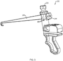
- FIG. 3 An alternative example of a drill guide assembly 300 is shown in FIG. 3 .
- a spring-loaded top knob 334 is used to adjust the height of the aimer arm 310 within the slots 308 in a non-stepped manner.
- the locking knob 314 is used to lock the height of the aimer arm 310 in place.
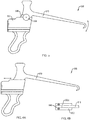
- the alignment member 406 includes a first plurality of teeth 440 spaced apart at a distance of about 1 mm.
- the plurality of teeth 440 are configured to engage a second plurality of teeth 442 ( FIG. 4B ) on the aimer arm 410 so that the height of the aimer arm 410 can be adjusted by 1 mm increments.
- a spring 422 is disposed within the alignment member 406 to ease the adjustment of the aimer arm 410.
- the locking knob 414 is used to lock the height of the aimer arm 410 in place.
- FIG. 5 Another example of a drill guide assembly 500 is shown in FIG. 5 .
- the aimer arm 510 is connected via a rotatable joint 544 to the guide body 502.
- the height of the aimer arm 510 is adjusted by moving the aimer arm 510 up or down relative to the guide body 502.
- a scale 546 on the guide body 502 would indicate the degree of adjustment in millimeters.
- the joint 544 could include a lock mechanism (e.g., a thumb wheel) to lock the aimer arm 510 at the desired height.
- FIGS. 6A and 6B An alternative example of a drill guide assembly 600 is shown in FIGS. 6A and 6B .
- a plurality of aimer arms 610 having different heights e.g., 5mm, 6mm, 7mm and 8mm
- a locking mechanism such as a thumb wheel or a click mechanism, would secure the aimer arm 610 in place.
- An alternative example of a drill guide assembly 700 shown in FIG. 7 , uses a parallelogram joint configuration. In the example of FIG. 7 , the fixed angle of the joint 744 is kept constant relative to the longitudinal axis L of the drill sleeve for all offsets.
- the aimer arm 710 is connected via the joints 744 and the lever arms 752 to the guide body 702 and a height of the aimer arm 710 can be adjusted by moving the aimer arm 710 up and down relative to the body 702.
- An additional device for example, a screw, an excenter, etc., along with a scale on the guide body 702, could be used to adjust the aimer arm 710 in a stepped or non-stepped manner.
Landscapes
- Health & Medical Sciences (AREA)
- Surgery (AREA)
- Life Sciences & Earth Sciences (AREA)
- Biomedical Technology (AREA)
- Medical Informatics (AREA)
- Orthopedic Medicine & Surgery (AREA)
- Oral & Maxillofacial Surgery (AREA)
- Engineering & Computer Science (AREA)
- Dentistry (AREA)
- Heart & Thoracic Surgery (AREA)
- Nuclear Medicine, Radiotherapy & Molecular Imaging (AREA)
- Molecular Biology (AREA)
- Animal Behavior & Ethology (AREA)
- General Health & Medical Sciences (AREA)
- Public Health (AREA)
- Veterinary Medicine (AREA)
- Surgical Instruments (AREA)
Abstract
Description
- This application claims priority to and benefit of
U.S. Provisional Application No. 62/876,031, filed July 19, 2019 - The present disclosure relates generally to surgical drill guides. More specifically, the present disclosure relates to adjustable drill guide assemblies for the positioning and orienting of bone tunnels to be drilled in a glenoid bone.
- A Latarjet operation, also known as the Latarjet-Bristow procedure, is a surgical procedure used to treat recurrent shoulder dislocations, typically caused by bone loss or a fracture of the glenoid. The Latarjet procedure typically involves the removal and transfer of a section of the coracoid process, as well as its attached soft tissue, to the glenoid cavity. This placement of the coracoid acts as a bone block which, combined with the transferred soft tissue, prevents further dislocation of the joint. During the procedure, holes are generally drilled through both of the coracoid and the glenoid through which screws or sutures attached to anchors or buttons can be placed for securing the section of the coracoid to the glenoid.
- Surgical drill guides can be used to place the holes in the glenoid neck at a fixed distance from the glenoid articulating surface to align with the drill holes of the coracoid. However, misalignment between the two sets of holes can occur. When the holes are misaligned, the suture/anchor or button constructs generally allow some tolerance in aligning the coracoid flush to the glenoid surface, because the suture has play within the drill holes. However, when a surgeon wants to use screws instead of the suture/anchor or button construct, retroactive alignment is not possible once the holes are drilled. Surgeons generally address the misalignment by shaving down the thickness of the coracoid with a burr. However, use of a burr can potentially cause cartilage damage and affect the accuracy of the surface alignment between the glenoid and the coracoid, as well as affecting surface quality.
- Described herein is a drill guide assembly in which the drill guide is adjustable for properly aligning the holes in the glenoid with the holes in the coracoid in a Latarjet procedure. The drill guide has an aimer arm extending from the body of the drill guide which has a fixed angle with respect to a drill sleeve inserted through the guide. The aimer arm can move up or down relative to the drill sleeve while maintaining the fixed angle relative to the drill sleeve by actuation of a translation member on the body. The aimer arm can move in a stepped fashion in 1 mm increments, or in a non-stepped fashion. A locking knob on the aimer arm can be used to lock the aimer arm at the desired position. Advantageously, the component parts of the drill guide assembly can be disassembled for cleaning.
- Examples of the drill guide assembly of this disclosure may include one or more of the following, in any suitable combination.
- In examples, a drill guide assembly of this disclosure includes an elongate body including a proximal end, a distal end and a longitudinal axis extending between the proximal and distal ends. At least one channel extends along the longitudinal axis of the body from the proximal end to the distal end. A sleeve is slidably disposed within the at least one channel. A distal end of the sleeve is configured to be secured to a first surface of a bone. An aimer arm extends distally from the body. A distal end of the aimer arm is configured to be secured to a second surface of the bone. The aimer arm extends at a fixed angle with respect to the sleeve. A vertical distance between the aimer arm and the sleeve is adjustable to a pre-selected distance by actuation of a translation member on the body such that the aimer arm maintains the fixed angle with respect to the sleeve.
- In examples, the assembly further includes a handle extending from a lower surface of the body configured to be held by a user. In examples, the preselected distance is between 6 mm and 9 mm. In examples, the at least one channel is two channels extending on opposing sides of the aimer arm, and a distance between the two channels is about 10 mm. In examples, the sleeve includes a bore extending from a proximal end to a distal end of the sleeve for the passage of a drill. In examples, the assembly further includes a locking mechanism for locking the sleeve at a predetermined position within the at least one channel. In examples, the proximal end of the sleeve includes a depth stop. A diameter of the depth stop selected to be larger than a diameter of the channel for limiting distal movement of the sleeve within the channel. In examples, the fixed angle is 10°. In examples, the distance between the aimer arm and the sleeve is adjustable in a stepped or a non-stepped manner. In examples, the assembly further includes an alignment member extending from an upper surface of the body adjacent the distal end of the body. The alignment member defines a plurality of longitudinal slots. In examples, the translation member is a rotatable wheel. In examples, the aimer arm extends through opposing ones of the plurality of slots along the longitudinal axis. A projection of the aimer arm is configured to serially engage the rotatable wheel such that the distance between the aimer arm and the sleeve is adjustable by rotation of the rotatable wheel by 90°. In examples, a pivot point of the rotatable wheel is offset from a center of the rotatable wheel in both a horizontal and a vertical direction. In examples, a proximal end of the aimer arm includes a locking knob for securing the aimer arm against the alignment member at the preselected distance. In examples, the assembly further includes a compression spring disposed within the alignment member for biasing the projection of the aimer arm against the rotatable wheel.
- Examples of a method for positioning a bone tunnel in bone of this disclosure include positioning a distal tip of an aimer arm of a drill guide assembly against a first surface of a bone. The drill guide assembly includes an elongate body including a proximal end, a distal end and a longitudinal axis extending between the proximal and distal ends. At least one channel extends along the longitudinal axis of the body from the proximal end to the distal end. A sleeve is slidably disposed within the at least one channel. A distal end of the sleeve is configured to be secured to a second surface of the bone. The aimer arm extends from the body at a fixed angle with respect to the sleeve. The method also includes advancing the sleeve through the at least one channel, whereby the bone is fixed between the distal tip of the aimer arm and the distal end of the sleeve. The method also includes actuating a translation member on the body such that a vertical distance between the aimer arm and the sleeve is adjusted to a preselected distance while maintaining the fixed angle with respect to the sleeve.
- In further examples, the translation member is a rotatable wheel, and actuating the translation member includes rotating the rotatable wheel by 90°. In examples, the method also includes locking the aimer arm at the preselected distance. In examples, the vertical distance between the aimer arm and the drill sleeve is adjusted in a stepped or a non-stepped manner. In examples, the method further includes locking the sleeve within the channel at a preselected position with a locking mechanism. In examples, the fixed angle is 10°. In examples, the preselected distance is between 6 mm and 9 mm.
- These and other features and advantages will be apparent from a reading of the following detailed description and a review of the associated drawings. It is to be understood that both the foregoing general description and the following detailed description are explanatory only and are not restrictive of aspects as claimed.
- The disclosure will be more fully understood by reference to the detailed description, in conjunction with the following figures, wherein:
-
FIGS. 1A and 1B are perspective views of an exemplary drill guide assembly of this disclosure; -
FIG. 1C is a detailed view of the side wheel of the drill guide assembly ofFIGS. 1A and 1B ; -
FIG. 1D is an assembled view of the drill guide assembly of this disclosure; -
FIG. 2 illustrates the use of the drill guide assembly of this disclosure; -
FIG. 3 illustrates an alternative example of the drill guide assembly of this disclosure; -
FIGS. 4A and 4B illustrate another alternative example of the drill guide assembly of this disclosure; -
FIG. 5 illustrates another alternative example of the drill guide assembly of this disclosure; -
FIGS. 6A and 6B illustrate yet another alternative example of the drill guide assembly of this disclosure; and -
FIG. 7 illustrates another alternative example of the drill guide assembly of this disclosure. - In the description that follows, like components have been given the same reference numerals, regardless of whether they are shown in different examples. To illustrate example(s) in a clear and concise manner, the drawings may not necessarily be to scale and certain features may be shown in somewhat schematic form. Features that are described and/or illustrated with respect to one example may be used in the same way or in a similar way in one or more other examples and/or in combination with or instead of the features of the other examples.
- As used in the specification and claims, for the purposes of describing and defining the invention, the terms "about" and "substantially" are used to represent the inherent degree of uncertainty that may be attributed to any quantitative comparison, value, measurement, or other representation. The terms "about" and "substantially" are also used herein to represent the degree by which a quantitative representation may vary from a stated reference without resulting in a change in the basic function of the subject matter at issue. "Comprise," "include," and/or plural forms of each are open ended and include the listed parts and can include additional parts that are not listed. "And/or" is open-ended and includes one or more of the listed parts and combinations of the listed parts. Use of the terms "upper," "lower," and the like is intended only to help in the clear description of the present disclosure and are not intended to limit the structure, positioning and/or operation of the disclosure in any manner.
- Referring now to
FIG. 1A , an exemplarydrill guide assembly 100 of this disclosure is shown in a perspective view. Theassembly 100 includes aguide body 102 having aproximal end 102a and adistal end 102b. Anupper surface 102c and alower surface 102d extend between theproximal end 102a and thedistal end 102b of thebody 102. Ahandle 104 extends from thelower surface 102d of thebody 102 and is configured to be held by a user in a "pistol-style" configuration. In alternative examples, not shown, thehandle 104 is an in-line handle, formed substantially coaxially with thebody 102. Thebody 102 further includes at least onecylindrical channel 120 extending from theproximal end 102a to thedistal end 102b of thebody 102 for slidably receiving an elongate drill sleeve 134 (FIG. ID). Thedrill sleeve 134 is configured for the passage of a guidewire (not shown) for locating the bone tunnels to be drilled in the bone. In the example ofFIG. 1A , twochannels 120 are defined on opposite sides of thebody 102 configured for positioning two parallel bone tunnels through the bone. In examples, a distance between thechannels 120 is about 10 mm, ensuring accurate and consistent placement of the bone tunnels about 10 mm apart within the bone. Anelongate aimer arm 110 extends distally from thebody 102 at about a 10° angle toward the longitudinal axis L of a path defined by thechannels 120 for insertion of thedrill sleeve 134. Theaimer arm 110 includes adistal tip 116 with aspiked hook 118 which is configured to contact a bone surface. In alternative examples, not shown, thedistal tip 116 could be pointed or comprise a blunted end, such as a spherical tip. Theassembly 100 is configured such that a vertical distance between theaimer arm 110 and thedrill sleeve 134 is adjustable based on a pre-measured thickness of the bone to be drilled by actuation of a translation member on the body, such as arotatable wheel 126, while still maintaining the 10° angle between theaimer arm 110 and thedrill sleeve 134. Theupper surface 102c of thebody 102 also includes at least one threadedopening 128 adjacent theproximal end 102a for receiving a threaded ratchet pawl (not shown) for locking thedrill sleeve 134 within thechannel 120 at a desired position. - Turning now to
FIG. 1B , in the example of theassembly 100, analignment member 106 extends from theupper surface 102c of thebody 102 adjacent thedistal end 102b. Thealignment member 106 defines a plurality oflongitudinal slots 108 within thealignment member 106. Theaimer arm 110 extends through opposingslots 108 along the longitudinal axis and is vertically moveable within theslots 108 relative to thedrill sleeve 134. A proximal end of theaimer arm 110 includes a lockingknob 114 which can be used to secure theaimer arm 110 in the desired vertical position within theslots 108. Aprojection 112 on theaimer arm 110 extends through athird slot 108 and is configured to serially engage a flat edge of therotatable wheel 126, as further described below. Acompression spring 122 is disposed within thealignment member 106 between theaimer arm 110 and anupper knob 124. Thespring 122 is configured to bias theprojection 112 of theaimer arm 110 against therotatable wheel 126. InFIG. 1B , therotatable wheel 126 is shown rotated 90° from the position of therotatable wheel 126 shown inFIG. 1A . InFIG. 1B , thespring 122 is also shown as more compressed and theaimer arm 110 in a higher vertical position than thespring 122 and theaimer arm 110 ofFIG. 1A . - Turning now to
FIG. 1C , therotatable wheel 126 includes apivot point 127 that is offset from the center of therotatable wheel 126 in both a horizontal and vertical direction. For example, thepivot point 127 may be disposed at a first distance A from a firstflat edge 126a of therotatable wheel 126 selected to be smaller than a second distance B from a secondflat edge 126b of therotatable wheel 126 in a horizontal direction. In examples, the first distance A may be 8 mm and second distance B may be 9 mm. Similarly, thepivot point 127 may be disposed at a third distance C from a third flat edge 126c of therotatable wheel 126 selected to be smaller than a fourth distance D from a fourthflat edge 126d of therotatable wheel 126 in a vertical direction. In examples, the third distance C may be 7 mm and the fourth distance D may be 10 mm. In this manner, by a 90° rotation of therotatable wheel 126, the distance between theaimer arm 110 and thedrill sleeve 134 may be adjusted in a stepped manner in 1 mm increments from about 6 mm to about 9 mm. - Turning now to FIG. ID, the
drill guide assembly 100 is shown withdrill sleeves 134 inserted through thechannels 120. Eachdrill sleeve 134 includes adepth stop 136 at a proximal end of thedrill sleeve 134. Thedepth stop 136 can be used by a surgeon to grasp and manipulate thedrill sleeve 134 during surgery. Thedepth stop 136 has a larger outer diameter than that of thechannel 120, such that whendrill sleeve 134 is inserted through thechannel 120, thedepth stop 136 preventsdrill sleeve 134 from being inserted completely through thechannel 120. The distal end of thedrill sleeve 134 may be angled and include a plurality ofteeth 135 for securing thedrill sleeve 134 against bone. A diameter of aproximal portion 134a of thedrill sleeve 134 is selected to be larger than a diameter of adistal portion 134b of thedrill sleeve 134. Thedrill sleeve 134 has a cylindrical bore 138 (FIG. 2A ) extending through thedrill sleeve 134 which provides a passageway for a guidewire (not shown). Theproximal portion 134a of thedrill sleeve 134 also includes arack 140 in the form of a series of ratchet teeth or radial grooves along one side ofdrill sleeve 134. A ratchet pawl 130 (FIG. 2A ) is configured to engage with therack 140 and lock thedrill sleeve 134 in a desired position withinchannel 120. - The use of the
drill guide assembly 100 will now be described with reference toFIG. 2 . The glenoid 132 may be initially prepared for the procedure by rasping theinferior surface 132a of the glenoid 132 for better attachment to the coracoid. Initially, drill holes 150 are drilled in a center of the coracoid 151 at a distance from thelateral border 151a (typically 5 to 9 mm from thelateral border 151a, depending on the width of the coracoid 151). The distance of the drill holes 150 to thelateral border 151a of the coracoid 151 is measured and the result is used to set the pre-selected distance of theaimer arm 110 from thedrill sleeve 134. For example, if the distance of the drill holes 150 from thelateral border 151a of the coracoid 151 is 6 mm, the distance of theaimer arm 110 from thedrill sleeve 134 is selected to be 6 mm. After an incision is made to introduce theassembly 100 into the patient's shoulder, the surgeon adjusts the orientation ofaimer arm 110 until thehook 118 is placed on theinferior surface 132a of the glenoid 132 to hold theaimer arm 110 in place, making sure that the under surface of theaimer arm 110 is in full contact with glenoid cartilage. Thedrill sleeve 134 is then inserted throughchannel 120 of theassembly 100 so that the distal tip of thedrill sleeve 134 is flush against theanterior surface 132b of the glenoid 132. Thedrill sleeve 134 is then locked into thechannel 120 by theratchet pawl 130. Subsequently, a drill (not shown) is inserted through thebore 138 of thedrill sleeve 134 and drilled through the glenoid 132. Theassembly 100 is then removed from the patient's shoulder. - An alternative example of a
drill guide assembly 300 is shown inFIG. 3 . In the example ofFIG. 3 , a spring-loadedtop knob 334 is used to adjust the height of theaimer arm 310 within theslots 308 in a non-stepped manner. The lockingknob 314 is used to lock the height of theaimer arm 310 in place. In an alternative example of adrill guide assembly 400, shown inFIGS. 4A and 4B , thealignment member 406 includes a first plurality ofteeth 440 spaced apart at a distance of about 1 mm. The plurality ofteeth 440 are configured to engage a second plurality of teeth 442 (FIG. 4B ) on theaimer arm 410 so that the height of theaimer arm 410 can be adjusted by 1 mm increments. Aspring 422 is disposed within thealignment member 406 to ease the adjustment of theaimer arm 410. The locking knob 414 is used to lock the height of theaimer arm 410 in place. - Another example of a
drill guide assembly 500 is shown inFIG. 5 . In the example ofFIG. 5 , theaimer arm 510 is connected via a rotatable joint 544 to theguide body 502. The height of theaimer arm 510 is adjusted by moving theaimer arm 510 up or down relative to theguide body 502. Ascale 546 on theguide body 502 would indicate the degree of adjustment in millimeters. The joint 544 could include a lock mechanism (e.g., a thumb wheel) to lock theaimer arm 510 at the desired height. - An alternative example of a
drill guide assembly 600 is shown inFIGS. 6A and 6B . In the example ofFIGS. 6A and 6B , a plurality ofaimer arms 610 having different heights (e.g., 5mm, 6mm, 7mm and 8mm) could be configured to slide into a T-shapedslot 648 on a top surface 602c of theguide body 602. A locking mechanism, such as a thumb wheel or a click mechanism, would secure theaimer arm 610 in place. An alternative example of adrill guide assembly 700, shown inFIG. 7 , uses a parallelogram joint configuration. In the example ofFIG. 7 , the fixed angle of the joint 744 is kept constant relative to the longitudinal axis L of the drill sleeve for all offsets. Theaimer arm 710 is connected via thejoints 744 and thelever arms 752 to theguide body 702 and a height of theaimer arm 710 can be adjusted by moving theaimer arm 710 up and down relative to thebody 702. An additional device (for example, a screw, an excenter, etc.), along with a scale on theguide body 702, could be used to adjust theaimer arm 710 in a stepped or non-stepped manner. - One skilled in the art will realize the disclosure may be embodied in other specific forms without departing from the spirit or essential characteristics thereof. The foregoing examples are therefore to be considered in all respects illustrative rather than limiting of the disclosure described herein. Scope of the disclosure is thus indicated by the appended claims, rather than by the foregoing description, and all changes that come within the meaning and range of equivalency of the claims are therefore intended to be embraced therein.
Claims (20)
- A drill guide assembly, comprising:an elongate body including a proximal end, a distal end and a longitudinal axis extending between the proximal and distal ends;at least one channel extending along the longitudinal axis of the body from the proximal end to the distal end;a sleeve slidably disposed within the at least one channel, a distal end of the sleeve configured to be secured to a first surface of a bone;an aimer arm extending distally from the body, a distal end of the aimer arm configured to be secured to a second surface of the bone, the aimer arm extending at a fixed angle with respect to the sleeve;wherein a vertical distance between the aimer arm and the sleeve is adjustable to a pre-selected distance by actuation of a translation member on the body such that the aimer arm maintains the fixed angle with respect to the sleeve.
- The assembly of claim 1, further comprising a handle extending from a lower surface of the body configured to be held by a user.
- The assembly of claim 1, wherein the preselected distance is between 6 mm and 9 mm.
- The assembly of claim 1, wherein the at least one channel is two channels extending on opposing sides of the aimer arm, and wherein a distance between the two channels is about 10 mm.
- The assembly of claim 1, wherein the sleeve comprises a bore extending from a proximal end to a distal end of the sleeve for the passage of a drill.
- The assembly of claim 1, further comprising a locking mechanism for locking the sleeve at a predetermined position within the at least one channel.
- The assembly of claim 1, wherein the proximal end of the sleeve comprises a depth stop, a diameter of the depth stop selected to be larger than a diameter of the channel for limiting distal movement of the sleeve within the channel.
- The assembly of claim 1, wherein the fixed angle is 10°.
- The assembly of claim 1, wherein the distance between the aimer arm and the sleeve is adjustable in a stepped or a non-stepped manner.
- The assembly of claim 1, further comprising an alignment member extending from an upper surface of the body adjacent the distal end of the body, the alignment member defining a plurality of longitudinal slots;
wherein the translation member is a rotatable wheel; and
wherein the aimer arm extends through opposing ones of the plurality of slots along the longitudinal axis, a projection of the aimer arm configured to serially engage the rotatable wheel such that the distance between the aimer arm and the sleeve is adjustable by rotation of the rotatable wheel by 90°. - The assembly of claim 10, wherein a pivot point of the rotatable wheel is offset from a center of the rotatable wheel in both a horizontal and a vertical direction.
- The assembly of claim 10, wherein a proximal end of the aimer arm comprises a locking knob for securing the aimer arm against the alignment member at the preselected distance.
- The assembly of claim 10, further comprising a compression spring disposed within the alignment member for biasing the projection of the aimer arm against the rotatable wheel.
- A method for positioning a bone tunnel in bone comprising:positioning a distal tip of an aimer arm of a drill guide assembly against a first surface of a bone, the drill guide assembly comprising:an elongate body including a proximal end, a distal end and a longitudinal axis extending between the proximal and distal ends;at least one channel extending along the longitudinal axis of the body from the proximal end to the distal end; anda sleeve slidably disposed within the at least one channel, a distal end of the sleeve configured to be secured to a second surface of the bone;wherein the aimer arm extends from the body at a fixed angle with respect to the sleeve;advancing the sleeve through the at least one channel, whereby the bone is fixed between the distal tip of the aimer arm and the distal end of the sleeve; andactuating a translation member on the body such that a vertical distance between the aimer arm and the sleeve is adjusted to a preselected distance while maintaining the fixed angle with respect to the sleeve.
- The method of claim 14, wherein the translation member is a rotatable wheel, and wherein the actuating the translation member comprises rotating the rotatable wheel by 90°.
- The method of claim 14, further comprising locking the aimer arm at the preselected distance.
- The method of claim 14, wherein the vertical distance between the aimer arm and the drill sleeve is adjusted in a stepped or a non-stepped manner.
- The method of claim 14, further comprising locking the sleeve within the channel at a preselected position with a locking mechanism.
- The method of claim 14, wherein the fixed angle is 10°.
- The method of claim 14, wherein the preselected distance is between 6 mm and 9 mm.
Applications Claiming Priority (1)
| Application Number | Priority Date | Filing Date | Title |
|---|---|---|---|
| US201962876031P | 2019-07-19 | 2019-07-19 |
Publications (3)
| Publication Number | Publication Date |
|---|---|
| EP3766438A2 true EP3766438A2 (en) | 2021-01-20 |
| EP3766438A3 EP3766438A3 (en) | 2021-04-21 |
| EP3766438B1 EP3766438B1 (en) | 2024-09-11 |
Family
ID=71670083
Family Applications (1)
| Application Number | Title | Priority Date | Filing Date |
|---|---|---|---|
| EP20186416.2A Active EP3766438B1 (en) | 2019-07-19 | 2020-07-17 | Adjustable drill guide |
Country Status (2)
| Country | Link |
|---|---|
| US (2) | US11172943B2 (en) |
| EP (1) | EP3766438B1 (en) |
Cited By (1)
| Publication number | Priority date | Publication date | Assignee | Title |
|---|---|---|---|---|
| CN118845143A (en) * | 2024-09-25 | 2024-10-29 | 浙江德康医疗器械有限公司 | Aiming module, intramedullary nail aiming arm and intramedullary nail aiming device |
Families Citing this family (6)
| Publication number | Priority date | Publication date | Assignee | Title |
|---|---|---|---|---|
| US11298143B2 (en) * | 2017-04-12 | 2022-04-12 | Smith & Nephew, Inc. | Surgical drill guide systems and methods of use thereof |
| US11819425B2 (en) * | 2021-04-29 | 2023-11-21 | Cc-Instruments Oy | Coracoid guiding system and a method for using thereof |
| US12329393B2 (en) * | 2021-08-10 | 2025-06-17 | Wright Medical Technology, Inc. | Targeting guide |
| US20240058022A1 (en) * | 2022-08-22 | 2024-02-22 | The Research Foundation For The State University Of New York | Surgical guide devices and surgical clamps including same |
| US20250040943A1 (en) * | 2023-08-04 | 2025-02-06 | Reconstruct Medical Supply LLC | Acl drill guide assembly |
| WO2025122698A1 (en) * | 2023-12-06 | 2025-06-12 | Smith & Nephew, Inc. | Methods and systems for tunnel planning and navigation |
Family Cites Families (24)
| Publication number | Priority date | Publication date | Assignee | Title |
|---|---|---|---|---|
| US4708139A (en) * | 1986-02-24 | 1987-11-24 | Dunbar Iv William H | Arthroscopic drill guide |
| US4739751A (en) * | 1986-10-03 | 1988-04-26 | Temple University | Apparatus and method for reconstructive surgery |
| US5300077A (en) * | 1990-07-16 | 1994-04-05 | Arthrotek | Method and instruments for ACL reconstruction |
| US6019767A (en) * | 1990-07-16 | 2000-02-01 | Arthrotek | Tibial guide |
| US5163940A (en) | 1991-03-04 | 1992-11-17 | American Cyanamid Company | Surgical drill guide for tibia |
| US5681333A (en) | 1995-11-08 | 1997-10-28 | Arthrex, Inc. | Method and apparatus for arthroscopic rotator cuff repair utilizing bone tunnels for suture attachment |
| US5968050A (en) | 1997-12-05 | 1999-10-19 | Smith & Nephew, Inc. | Positioning a tibial tunnel |
| US9468449B2 (en) | 2010-12-02 | 2016-10-18 | Smith & Nephew, Inc. | Reconstructive joint tunnel drilling locator |
| US8617168B2 (en) * | 2010-10-25 | 2013-12-31 | Smith & Nephew, Inc. | Oval tibia guide |
| WO2012061733A1 (en) * | 2010-11-04 | 2012-05-10 | Smith & Nephew, Inc. | Drill guide depth stop |
| MX348238B (en) * | 2011-03-09 | 2017-05-29 | Smith & Nephew Inc | Multiple portal guide. |
| WO2012170425A1 (en) * | 2011-06-06 | 2012-12-13 | Smith & Nephew, Inc. | Drill guide for shoulder |
| US8685033B2 (en) | 2011-06-27 | 2014-04-01 | Smith & Nephew, Inc. | Anatomic femoral guide |
| ES2415960B1 (en) * | 2011-10-06 | 2014-05-27 | Jose Manuel Abascal Rubio | TENSION DEVICE OF ONE OR MORE FASCICULAR BRANCHES OF SOFT MATERIAL OVERHEADING BY A BONE TUNNEL. |
| EP2852217B1 (en) | 2012-05-14 | 2016-10-19 | Huawei Technologies Co., Ltd. | Service indication message reporting method, device and system |
| AU2014228420B2 (en) | 2013-03-15 | 2018-11-08 | Smith & Nephew, Inc. | Surgical fastening |
| US10123813B2 (en) | 2014-02-17 | 2018-11-13 | Smith & Nephew, Inc. | Drill guide |
| RU2016151477A (en) * | 2014-06-13 | 2018-07-13 | Смит Энд Нефью, Инк. | METHOD FOR CORRECTING SHOULDER JOINT INSTABILITY |
| US10045789B2 (en) | 2014-09-30 | 2018-08-14 | Medos International Sàrl | Universal surgical guide systems and methods |
| US10098646B2 (en) * | 2014-09-30 | 2018-10-16 | Medos International Sàrl | Surgical guide for use in ligament repair procedures |
| CN105411657B (en) | 2015-12-23 | 2018-06-05 | 雷俊虎 | Orthopaedics glenoid lip of articulation of humerus fix tool system |
| DE102016103642A1 (en) * | 2016-03-01 | 2017-09-07 | Karl Storz Gmbh & Co. Kg | Targeting device for aligning a surgical drilling instrument |
| CN106618720B (en) * | 2017-01-11 | 2023-05-05 | 海口市人民医院 | Vertical adjustable fixed-point offset guide needle aiming hollow nail fixing minimally invasive device |
| CN107961057B (en) * | 2018-01-02 | 2020-02-07 | 吉林大学 | Coracoid clavicle closing and punching sighting device |
-
2020
- 2020-07-17 EP EP20186416.2A patent/EP3766438B1/en active Active
- 2020-07-17 US US16/931,538 patent/US11172943B2/en active Active
-
2021
- 2021-10-20 US US17/505,856 patent/US11911047B2/en active Active
Cited By (1)
| Publication number | Priority date | Publication date | Assignee | Title |
|---|---|---|---|---|
| CN118845143A (en) * | 2024-09-25 | 2024-10-29 | 浙江德康医疗器械有限公司 | Aiming module, intramedullary nail aiming arm and intramedullary nail aiming device |
Also Published As
| Publication number | Publication date |
|---|---|
| US11911047B2 (en) | 2024-02-27 |
| EP3766438A3 (en) | 2021-04-21 |
| US11172943B2 (en) | 2021-11-16 |
| EP3766438B1 (en) | 2024-09-11 |
| US20210015503A1 (en) | 2021-01-21 |
| US20220039809A1 (en) | 2022-02-10 |
Similar Documents
| Publication | Publication Date | Title |
|---|---|---|
| EP3766438B1 (en) | Adjustable drill guide | |
| US20230139017A1 (en) | Lateral mass fixation system | |
| US20240245413A1 (en) | Chevron osteotomy tools and methods | |
| US11253307B2 (en) | Suprapatellar insertion system, kit and method | |
| US9888930B2 (en) | Aiming device | |
| ES2521619T3 (en) | Help for the selection of a bone plate | |
| US8231661B2 (en) | Systems and methods for minimally invasive facet fusion | |
| US10349990B2 (en) | Method and device for attaching a bone plate | |
| US7141074B2 (en) | Variable depth drill with self-centering sleeve | |
| US5312412A (en) | Fixation alignment guide for surgical use | |
| CN101730837B (en) | Medical aligning device | |
| US12369952B2 (en) | Bone tie and portal | |
| US8439932B2 (en) | Submuscular plating system | |
| US8585705B2 (en) | Percutaneous instrumentation and surgical procedure | |
| US20050177171A1 (en) | Surgical drill guide | |
| JP2007531590A (en) | Drill bit with adjustable depth | |
| CA2406166A1 (en) | Dual drill guide for a locking bone plate | |
| CN101969865A (en) | Medical device and method | |
| US8372080B2 (en) | Trans-cut slot adjustment mechanism | |
| WO2020172451A1 (en) | System and method for high tibial osteotomy | |
| US12433532B2 (en) | Flexion/extension surgical guides and methods of using the same | |
| US20260130676A1 (en) | Apparatus and method for forming a cavity in a sacroiliac joint | |
| WO2018190971A2 (en) | Surgical drill guide systems and methods of use thereof | |
| AU2005201206B2 (en) | Instruments and methods for stabilization of bony structures |
Legal Events
| Date | Code | Title | Description |
|---|---|---|---|
| PUAI | Public reference made under article 153(3) epc to a published international application that has entered the european phase |
Free format text: ORIGINAL CODE: 0009012 |
|
| STAA | Information on the status of an ep patent application or granted ep patent |
Free format text: STATUS: THE APPLICATION HAS BEEN PUBLISHED |
|
| AK | Designated contracting states |
Kind code of ref document: A2 Designated state(s): AL AT BE BG CH CY CZ DE DK EE ES FI FR GB GR HR HU IE IS IT LI LT LU LV MC MK MT NL NO PL PT RO RS SE SI SK SM TR |
|
| AX | Request for extension of the european patent |
Extension state: BA ME |
|
| PUAL | Search report despatched |
Free format text: ORIGINAL CODE: 0009013 |
|
| AK | Designated contracting states |
Kind code of ref document: A3 Designated state(s): AL AT BE BG CH CY CZ DE DK EE ES FI FR GB GR HR HU IE IS IT LI LT LU LV MC MK MT NL NO PL PT RO RS SE SI SK SM TR |
|
| AX | Request for extension of the european patent |
Extension state: BA ME |
|
| RIC1 | Information provided on ipc code assigned before grant |
Ipc: A61B 17/17 20060101AFI20210315BHEP |
|
| STAA | Information on the status of an ep patent application or granted ep patent |
Free format text: STATUS: REQUEST FOR EXAMINATION WAS MADE |
|
| 17P | Request for examination filed |
Effective date: 20211021 |
|
| RBV | Designated contracting states (corrected) |
Designated state(s): AL AT BE BG CH CY CZ DE DK EE ES FI FR GB GR HR HU IE IS IT LI LT LU LV MC MK MT NL NO PL PT RO RS SE SI SK SM TR |
|
| STAA | Information on the status of an ep patent application or granted ep patent |
Free format text: STATUS: EXAMINATION IS IN PROGRESS |
|
| 17Q | First examination report despatched |
Effective date: 20230203 |
|
| GRAP | Despatch of communication of intention to grant a patent |
Free format text: ORIGINAL CODE: EPIDOSNIGR1 |
|
| STAA | Information on the status of an ep patent application or granted ep patent |
Free format text: STATUS: GRANT OF PATENT IS INTENDED |
|
| INTG | Intention to grant announced |
Effective date: 20240222 |
|
| P01 | Opt-out of the competence of the unified patent court (upc) registered |
Effective date: 20240222 |
|
| GRAS | Grant fee paid |
Free format text: ORIGINAL CODE: EPIDOSNIGR3 |
|
| GRAA | (expected) grant |
Free format text: ORIGINAL CODE: 0009210 |
|
| STAA | Information on the status of an ep patent application or granted ep patent |
Free format text: STATUS: THE PATENT HAS BEEN GRANTED |
|
| AK | Designated contracting states |
Kind code of ref document: B1 Designated state(s): AL AT BE BG CH CY CZ DE DK EE ES FI FR GB GR HR HU IE IS IT LI LT LU LV MC MK MT NL NO PL PT RO RS SE SI SK SM TR |
|
| REG | Reference to a national code |
Ref country code: GB Ref legal event code: FG4D |
|
| REG | Reference to a national code |
Ref country code: CH Ref legal event code: EP |
|
| REG | Reference to a national code |
Ref country code: DE Ref legal event code: R096 Ref document number: 602020037429 Country of ref document: DE |
|
| REG | Reference to a national code |
Ref country code: IE Ref legal event code: FG4D |
|
| REG | Reference to a national code |
Ref country code: LT Ref legal event code: MG9D |
|
| PG25 | Lapsed in a contracting state [announced via postgrant information from national office to epo] |
Ref country code: NO Free format text: LAPSE BECAUSE OF FAILURE TO SUBMIT A TRANSLATION OF THE DESCRIPTION OR TO PAY THE FEE WITHIN THE PRESCRIBED TIME-LIMIT Effective date: 20241211 |
|
| REG | Reference to a national code |
Ref country code: NL Ref legal event code: MP Effective date: 20240911 |
|
| PG25 | Lapsed in a contracting state [announced via postgrant information from national office to epo] |
Ref country code: GR Free format text: LAPSE BECAUSE OF FAILURE TO SUBMIT A TRANSLATION OF THE DESCRIPTION OR TO PAY THE FEE WITHIN THE PRESCRIBED TIME-LIMIT Effective date: 20241212 Ref country code: FI Free format text: LAPSE BECAUSE OF FAILURE TO SUBMIT A TRANSLATION OF THE DESCRIPTION OR TO PAY THE FEE WITHIN THE PRESCRIBED TIME-LIMIT Effective date: 20240911 |
|
| PG25 | Lapsed in a contracting state [announced via postgrant information from national office to epo] |
Ref country code: BG Free format text: LAPSE BECAUSE OF FAILURE TO SUBMIT A TRANSLATION OF THE DESCRIPTION OR TO PAY THE FEE WITHIN THE PRESCRIBED TIME-LIMIT Effective date: 20240911 |
|
| PG25 | Lapsed in a contracting state [announced via postgrant information from national office to epo] |
Ref country code: LV Free format text: LAPSE BECAUSE OF FAILURE TO SUBMIT A TRANSLATION OF THE DESCRIPTION OR TO PAY THE FEE WITHIN THE PRESCRIBED TIME-LIMIT Effective date: 20240911 |
|
| PG25 | Lapsed in a contracting state [announced via postgrant information from national office to epo] |
Ref country code: HR Free format text: LAPSE BECAUSE OF FAILURE TO SUBMIT A TRANSLATION OF THE DESCRIPTION OR TO PAY THE FEE WITHIN THE PRESCRIBED TIME-LIMIT Effective date: 20240911 |
|
| PG25 | Lapsed in a contracting state [announced via postgrant information from national office to epo] |
Ref country code: RS Free format text: LAPSE BECAUSE OF FAILURE TO SUBMIT A TRANSLATION OF THE DESCRIPTION OR TO PAY THE FEE WITHIN THE PRESCRIBED TIME-LIMIT Effective date: 20241211 Ref country code: ES Free format text: LAPSE BECAUSE OF FAILURE TO SUBMIT A TRANSLATION OF THE DESCRIPTION OR TO PAY THE FEE WITHIN THE PRESCRIBED TIME-LIMIT Effective date: 20240911 |
|
| PG25 | Lapsed in a contracting state [announced via postgrant information from national office to epo] |
Ref country code: RS Free format text: LAPSE BECAUSE OF FAILURE TO SUBMIT A TRANSLATION OF THE DESCRIPTION OR TO PAY THE FEE WITHIN THE PRESCRIBED TIME-LIMIT Effective date: 20241211 Ref country code: NO Free format text: LAPSE BECAUSE OF FAILURE TO SUBMIT A TRANSLATION OF THE DESCRIPTION OR TO PAY THE FEE WITHIN THE PRESCRIBED TIME-LIMIT Effective date: 20241211 Ref country code: LV Free format text: LAPSE BECAUSE OF FAILURE TO SUBMIT A TRANSLATION OF THE DESCRIPTION OR TO PAY THE FEE WITHIN THE PRESCRIBED TIME-LIMIT Effective date: 20240911 Ref country code: HR Free format text: LAPSE BECAUSE OF FAILURE TO SUBMIT A TRANSLATION OF THE DESCRIPTION OR TO PAY THE FEE WITHIN THE PRESCRIBED TIME-LIMIT Effective date: 20240911 Ref country code: GR Free format text: LAPSE BECAUSE OF FAILURE TO SUBMIT A TRANSLATION OF THE DESCRIPTION OR TO PAY THE FEE WITHIN THE PRESCRIBED TIME-LIMIT Effective date: 20241212 Ref country code: FI Free format text: LAPSE BECAUSE OF FAILURE TO SUBMIT A TRANSLATION OF THE DESCRIPTION OR TO PAY THE FEE WITHIN THE PRESCRIBED TIME-LIMIT Effective date: 20240911 Ref country code: ES Free format text: LAPSE BECAUSE OF FAILURE TO SUBMIT A TRANSLATION OF THE DESCRIPTION OR TO PAY THE FEE WITHIN THE PRESCRIBED TIME-LIMIT Effective date: 20240911 Ref country code: BG Free format text: LAPSE BECAUSE OF FAILURE TO SUBMIT A TRANSLATION OF THE DESCRIPTION OR TO PAY THE FEE WITHIN THE PRESCRIBED TIME-LIMIT Effective date: 20240911 |
|
| REG | Reference to a national code |
Ref country code: AT Ref legal event code: MK05 Ref document number: 1721986 Country of ref document: AT Kind code of ref document: T Effective date: 20240911 |
|
| PG25 | Lapsed in a contracting state [announced via postgrant information from national office to epo] |
Ref country code: NL Free format text: LAPSE BECAUSE OF FAILURE TO SUBMIT A TRANSLATION OF THE DESCRIPTION OR TO PAY THE FEE WITHIN THE PRESCRIBED TIME-LIMIT Effective date: 20240911 |
|
| PG25 | Lapsed in a contracting state [announced via postgrant information from national office to epo] |
Ref country code: PT Free format text: LAPSE BECAUSE OF FAILURE TO SUBMIT A TRANSLATION OF THE DESCRIPTION OR TO PAY THE FEE WITHIN THE PRESCRIBED TIME-LIMIT Effective date: 20250113 Ref country code: IS Free format text: LAPSE BECAUSE OF FAILURE TO SUBMIT A TRANSLATION OF THE DESCRIPTION OR TO PAY THE FEE WITHIN THE PRESCRIBED TIME-LIMIT Effective date: 20250111 |
|
| PG25 | Lapsed in a contracting state [announced via postgrant information from national office to epo] |
Ref country code: RO Free format text: LAPSE BECAUSE OF FAILURE TO SUBMIT A TRANSLATION OF THE DESCRIPTION OR TO PAY THE FEE WITHIN THE PRESCRIBED TIME-LIMIT Effective date: 20240911 Ref country code: SM Free format text: LAPSE BECAUSE OF FAILURE TO SUBMIT A TRANSLATION OF THE DESCRIPTION OR TO PAY THE FEE WITHIN THE PRESCRIBED TIME-LIMIT Effective date: 20240911 |
|
| PG25 | Lapsed in a contracting state [announced via postgrant information from national office to epo] |
Ref country code: AT Free format text: LAPSE BECAUSE OF FAILURE TO SUBMIT A TRANSLATION OF THE DESCRIPTION OR TO PAY THE FEE WITHIN THE PRESCRIBED TIME-LIMIT Effective date: 20240911 Ref country code: EE Free format text: LAPSE BECAUSE OF FAILURE TO SUBMIT A TRANSLATION OF THE DESCRIPTION OR TO PAY THE FEE WITHIN THE PRESCRIBED TIME-LIMIT Effective date: 20240911 |
|
| PG25 | Lapsed in a contracting state [announced via postgrant information from national office to epo] |
Ref country code: CZ Free format text: LAPSE BECAUSE OF FAILURE TO SUBMIT A TRANSLATION OF THE DESCRIPTION OR TO PAY THE FEE WITHIN THE PRESCRIBED TIME-LIMIT Effective date: 20240911 Ref country code: PL Free format text: LAPSE BECAUSE OF FAILURE TO SUBMIT A TRANSLATION OF THE DESCRIPTION OR TO PAY THE FEE WITHIN THE PRESCRIBED TIME-LIMIT Effective date: 20240911 |
|
| PG25 | Lapsed in a contracting state [announced via postgrant information from national office to epo] |
Ref country code: SK Free format text: LAPSE BECAUSE OF FAILURE TO SUBMIT A TRANSLATION OF THE DESCRIPTION OR TO PAY THE FEE WITHIN THE PRESCRIBED TIME-LIMIT Effective date: 20240911 Ref country code: IT Free format text: LAPSE BECAUSE OF FAILURE TO SUBMIT A TRANSLATION OF THE DESCRIPTION OR TO PAY THE FEE WITHIN THE PRESCRIBED TIME-LIMIT Effective date: 20240911 |
|
| REG | Reference to a national code |
Ref country code: DE Ref legal event code: R097 Ref document number: 602020037429 Country of ref document: DE |
|
| PG25 | Lapsed in a contracting state [announced via postgrant information from national office to epo] |
Ref country code: DK Free format text: LAPSE BECAUSE OF FAILURE TO SUBMIT A TRANSLATION OF THE DESCRIPTION OR TO PAY THE FEE WITHIN THE PRESCRIBED TIME-LIMIT Effective date: 20240911 |
|
| PGFP | Annual fee paid to national office [announced via postgrant information from national office to epo] |
Ref country code: GB Payment date: 20250619 Year of fee payment: 6 |
|
| PLBE | No opposition filed within time limit |
Free format text: ORIGINAL CODE: 0009261 |
|
| STAA | Information on the status of an ep patent application or granted ep patent |
Free format text: STATUS: NO OPPOSITION FILED WITHIN TIME LIMIT |
|
| 26N | No opposition filed |
Effective date: 20250612 |
|
| PG25 | Lapsed in a contracting state [announced via postgrant information from national office to epo] |
Ref country code: SE Free format text: LAPSE BECAUSE OF FAILURE TO SUBMIT A TRANSLATION OF THE DESCRIPTION OR TO PAY THE FEE WITHIN THE PRESCRIBED TIME-LIMIT Effective date: 20240911 |
|
| PGFP | Annual fee paid to national office [announced via postgrant information from national office to epo] |
Ref country code: DE Payment date: 20250618 Year of fee payment: 6 |
|
| REG | Reference to a national code |
Ref country code: CH Ref legal event code: H13 Free format text: ST27 STATUS EVENT CODE: U-0-0-H10-H13 (AS PROVIDED BY THE NATIONAL OFFICE) Effective date: 20260224 |
|
| PG25 | Lapsed in a contracting state [announced via postgrant information from national office to epo] |
Ref country code: LU Free format text: LAPSE BECAUSE OF NON-PAYMENT OF DUE FEES Effective date: 20250717 |
|
| REG | Reference to a national code |
Ref country code: BE Ref legal event code: MM Effective date: 20250731 |
|
| PG25 | Lapsed in a contracting state [announced via postgrant information from national office to epo] |
Ref country code: BE Free format text: LAPSE BECAUSE OF NON-PAYMENT OF DUE FEES Effective date: 20250731 |
|
| PG25 | Lapsed in a contracting state [announced via postgrant information from national office to epo] |
Ref country code: FR Free format text: LAPSE BECAUSE OF NON-PAYMENT OF DUE FEES Effective date: 20250731 |
|
| PG25 | Lapsed in a contracting state [announced via postgrant information from national office to epo] |
Ref country code: CH Free format text: LAPSE BECAUSE OF NON-PAYMENT OF DUE FEES Effective date: 20250731 |