EP3766400A1 - A spray arrangement for dishwashers - Google Patents
A spray arrangement for dishwashers Download PDFInfo
- Publication number
- EP3766400A1 EP3766400A1 EP20183623.6A EP20183623A EP3766400A1 EP 3766400 A1 EP3766400 A1 EP 3766400A1 EP 20183623 A EP20183623 A EP 20183623A EP 3766400 A1 EP3766400 A1 EP 3766400A1
- Authority
- EP
- European Patent Office
- Prior art keywords
- main body
- spray
- spray arm
- movement
- connection
- Prior art date
- Legal status (The legal status is an assumption and is not a legal conclusion. Google has not performed a legal analysis and makes no representation as to the accuracy of the status listed.)
- Granted
Links
Images


Classifications
-
- A—HUMAN NECESSITIES
- A47—FURNITURE; DOMESTIC ARTICLES OR APPLIANCES; COFFEE MILLS; SPICE MILLS; SUCTION CLEANERS IN GENERAL
- A47L—DOMESTIC WASHING OR CLEANING; SUCTION CLEANERS IN GENERAL
- A47L15/00—Washing or rinsing machines for crockery or tableware
- A47L15/14—Washing or rinsing machines for crockery or tableware with stationary crockery baskets and spraying devices within the cleaning chamber
- A47L15/18—Washing or rinsing machines for crockery or tableware with stationary crockery baskets and spraying devices within the cleaning chamber with movably-mounted spraying devices
- A47L15/22—Rotary spraying devices
- A47L15/23—Rotary spraying devices moved by means of the sprays
-
- A—HUMAN NECESSITIES
- A47—FURNITURE; DOMESTIC ARTICLES OR APPLIANCES; COFFEE MILLS; SPICE MILLS; SUCTION CLEANERS IN GENERAL
- A47L—DOMESTIC WASHING OR CLEANING; SUCTION CLEANERS IN GENERAL
- A47L15/00—Washing or rinsing machines for crockery or tableware
- A47L15/42—Details
- A47L15/4214—Water supply, recirculation or discharge arrangements; Devices therefor
- A47L15/4219—Water recirculation
- A47L15/4221—Arrangements for redirection of washing water, e.g. water diverters to selectively supply the spray arms
-
- A—HUMAN NECESSITIES
- A47—FURNITURE; DOMESTIC ARTICLES OR APPLIANCES; COFFEE MILLS; SPICE MILLS; SUCTION CLEANERS IN GENERAL
- A47L—DOMESTIC WASHING OR CLEANING; SUCTION CLEANERS IN GENERAL
- A47L15/00—Washing or rinsing machines for crockery or tableware
- A47L15/42—Details
- A47L15/4278—Nozzles
- A47L15/4282—Arrangements to change or modify spray pattern or direction
Definitions
- the present invention relates to spray arrangements for delivering a cleaning liquid onto dishes in dishwashers.
- Dishwashers generally comprise at least one cleaning compartment in which dishes are cleaned, at least one door controlling access into this compartment, at least one rack for placing the dishes to the compartment, and at least one spray arrangement for delivering a cleaning liquid (e.g. water and/or detergent water) to the dishes on the rack so as to clean the dishes.
- a cleaning liquid e.g. water and/or detergent water
- the spray arrangement comprises at least one (preferably, at least two) spray arm on which at least one angled nozzle is provided, wherein the spray arm can rotate around an axis with the effect of water ejected from the angled nozzle (water jet). Rotation of the spray arm ensures that the cleaning liquid is sprayed into a major part of the cleaning compartment.
- spray systems comprising a spray arm which is lengthens for the corner areas and shortens for the edge areas, wherein an example of such a spray arrangement is disclosed in US5842492A .
- a movement line which is formed to extend corner areas of the cleaning compartment, and the spray arm has a telescopic structure in connection with a line.
- the spray arm is lengthens towards the corner areas when approaching the corner areas and shortens when moving away from the corner areas. Therefore, the cleaning liquid can reach all areas inside the cleaning compartment in a more effective manner.
- use of a movement line requires an extra space inside the cleaning compartment and complicates the usage of system especially for the top spray arm.
- spray arrangements that can lengthen and shorten without using movement line are also available in the known art.
- the spray arm can be extended with the effect of water ejected from the angled nozzle while approaching the corner areas; however, since water pressure in the spray arrangement is much higher than the pressure that moves the spray arm, the spray arm cannot switch from its lengthened state to shortened state and thus, it gets stuck.
- the spray arrangement according to the present invention which is suitable for use in a dishwasher; wherein the dishwasher comprises a cleaning compartment in which the dishes are placed through a rack; such that the spray arrangement is located under and/or above the rack rotatable along a plane parallel to the base of the rack so that a cleaning liquid is sprayed to the dishes, the spray arrangement comprising:
- the spray arrangement according to the present invention cleaning liquid can be effectively delivered to a major part of the inner volume of the cleaning compartment, and dishes can be cleaned more efficiently and efficiently. Further, extendable/retractable spray arm is moved without using an external energy such as electricity; and the stuck problem that may occur while the spray arm, which is in the opened position during this movement, switches to the closed position can be solved in a simple and practical way by using the flexible delivery line. Therefore, an easy to use, cost-effective, practical and reliable spray arrangement can be achieved.
- An object of the present invention is to provide a spray arrangement for delivering a cleaning liquid effectively onto dishes placed at a cleaning compartment of the dishwasher.
- Another object of the present invention is to provide a spray arrangement having a spray arm which lengthens as it approaches corner areas of cleaning compartment and becomes shorter when corner areas are passed.
- a further object of the present invention is to provide a spray arrangement which allows both the dishes in the upper rack and the dishes in the lower rack to be cleaned effectively.
- Another object of the present invention is to provide a spray arrangement having a spray arm which can lengthen/shorten without requiring an extra space.
- Yet a further object of the present invention is to provide a spray arrangement in which the spray arm is prevented from getting stuck after lengthening.
- Another object of the present invention is to provide an easy to use, cost-effective, practical and reliable spray arrangement.
- Main body (1) Holder bearing (1a) First housing (1b) Second housing (1c) Connection member (1d) Movement channel (1e) Liquid inlet (1f) Spray arm (2) Angled hole (2a) Spray member (2b) Movement member (2c) Cover (3) Movement bearing (4) Connection slot (4a) Lug slot (4b) Liquid distribution member (5) Collection portion (5a) Distributing channel (5b) Delivery line (6) Intermediate cover (7) Fixed gear (8) Inlet portion (8a) Fixing portion (8b) First transfer member (9) First transfer body (9a) Movable gear (9b) Fourth connection section (9c) Sixth connection section (9d) Second transfer member (10) Second transfer body (10a) Fifth connection section (10b) Second chamber (c1) Delivery channel (c2) Third connection section (c3) Guide member (c4) Connection body (c5) First chamber (b1) First connection section (b2)
- Dishwashers comprise a cleaning compartment with quadrilateral section, and dirty dishes are placed at the cleaning compartment via a rack.
- There is provided at least one spray arrangement in the cleaning compartment the spray arrangement being located under and/or above the rack and rotating around an axis, preferably along a plane parallel to the base of the rack, so that a cleaning liquid is sprayed onto the dishes.
- the spray arrangement rotates around said axis with the effect of the liquid sprayed through an angled hole provided on a spray arm thereof and enables the cleaning liquid to reach any possible area within the cleaning compartment.
- the present invention provides a spray assembly for solving said problems.
- the spray arrangement according to the present invention is suitable for use in a dishwasher; wherein the dishwasher comprises a cleaning compartment in which the dishes are placed through a rack; such that the spray arrangement is located under and/or above the rack rotatable along a plane parallel to the base of the rack so that a cleaning liquid is sprayed to the dishes, the spray arrangement comprising: at least one main body (1) in the form of a chamber; at least one spray arm (2) which is in connection with a side of the main body (1) and at least a part of which passes through at least one opening provided at said side of the main body (1) so as to extend out of the main body (1), wherein the spray arm (2) has at least one angled hole (a water jet) (2a) thereon, enables the main body (1) (accordingly, itself) to rotate around an axis by spraying the cleaning liquid passing through the spray arm (2) through said angled hole (2a) by means of at least one passage opening provided at the side facing the main body (1) (e.g.
- part of the spray arm (2) extending out of the opening is the shortest, and in the opened position, part of the spray arm (2) extending out of the opening is the longest; at least one movement mechanism which is preferably located in the main body (1) and provides said movement of the spray arm (2) by transferring rotational movement of the main body (1) to the spray arm (2); and at least one liquid inlet (1f) located at the main body (1), wherein cleaning liquid received from a source is passed through the liquid inlet (1f) and delivered to the spray arm (2) and also to the dishes through holes on spray arm (2).
- the spray arrangement according to the present invention also comprises at least one holder bearing (1a) which is located above the opening, forms an arch shape above the opening and guides said movement of the spray arm (2), wherein the spray arm (2) is movably fitted at the space between the holder bearing (1a) and the opening; at least one liquid distribution member (5) which can rotate around said axis during the forward-backward movement of the spray arm (2) and has a closed chamber shape in connection with the liquid inlet (1f) from a side thereof, wherein the cleaning liquid from the liquid inlet (1f) is collected in the liquid distribution member (5) and distributed to the spray arm (2); and at least one delivery line (e.g. a hose) (6) which has a flexible form (i.e.
- the spray arrangement comprises at least two spray arms (2) located facing each other, and at least two delivery lines (6) each of which is connected to a spray arm (2).
- the cleaning liquid received into the spray arrangement through the liquid inlet (1f) reaches the liquid distribution member (5) and moves to the delivery lines (6) which are connected to the spray arms (2).
- the cleaning liquid which has moved through the delivery lines (6) reaches the spray arms (2), passes through the spray arms (2) and is sprayed through the holes on the spray arms (2) towards the dishes located in the dishwasher.
- Spraying the cleaning liquid through angled holes (2a) provided on the spray arms (2) causes the main body (1) to rotate around said axis, and with this rotational movement of the main body (1), the movement mechanism moves the spray arms (2), which are e.g. in the closed position, in the forward direction to bring the spray arms (2) into the opened position (on the contrary, it can also move the spray arms (2), which are in the open position, in the backward direction to ensure that the spray arms (2) is brought into the closed position).
- the spray arms (2) With rotational movement of the main body (1), the spray arms (2) lengthen as they approach corner areas of the cleaning compartment (more portion thereof extend out of the main body (1)); and when they are exactly aligned with the corner areas (for example, when they are positioned such that they fit perfectly with the diagonal of the cleaning compartment), they reach the opened position in which the extending part is maximum.
- the spray arms which start to move away from the corner area as the main body (1) continues to rotate, move backwards via the movement mechanism, and preferably, when they reach middle of the two successive corner areas, the spray arms (2) will have reached the closed position.
- the spray arms (2) in the closed position start to move forwards, and when they are aligned with another corner area, they will have reached the opened position.
- the spray arms (2) also move between closed/opened positions, thus the spray arms (2) are enabled to have the longest length when they are aligned with the exact corner areas and have the shortest length when they are aligned with middle areas of the lateral sides, so that dishes inside the cleaning compartment having quadrilateral section can be cleaned efficiently.
- movement of spray arms (2) is performed without an external energy (e.g. electric energy), thus avoiding an increase in the energy consumption.
- movement of spray arms (2) are enabled by rotational movement of main body (1) (i.e. by the thrust of the liquid sprayed through the angled hole (2) and rotating the main body (1)); in order for main body (1) to continue to rotate when the spray arms (2) have the longest length, i.e.
- delivery lines (6) which have a flexible form and a sufficient length in a way not to prevent the movement of the spray arms (2), and the cleaning liquid received from the liquid inlet (1f) is delivered to the spray arms (2) by these delivery lines (6) whose volume remain unchanged.
- parts in which the liquid delivery is carried out in the spray arrangement have a constant volume (i.e. the volume of the parts filled with cleaning liquid does not change) and hence the stuck problem can be avoided.
- additional equipment that require extra space in the cleaning compartment for the movement of spray arms (2) are no longer required, and the spray arrangement can be used efficiently for both the lower rack and the upper rack.
- the spray arrangement according to the invention preferably comprises at least one cover (3) which is located between the holder bearings (1a) and covers the main body (1) to form a closed chamber structure with the main body (1). Therefore, movable spray arm (2) and delivery line (6) are prevented from being displaced unintentionally and moving away from the main body (1) during movement.
- the spray arrangement preferably comprises at least one movement bearing (4), as illustrated in figure 8 , which is suitable for fixing to a surface in the cleaning compartment that is immobile during the operation of the dishwasher (e.g. base of the cleaning compartment, base of the rack where the dishes are placed), wherein the movement bearing (4) is connected to the liquid inlet (1f) via at least one connection slot (4a) in such a way as to allow rotational movement of the main body (1), thereby bearing the rotational movement of the main body (1), wherein the axis around which the main body (1) rotates passes through the connection slot (4a).
- the movement bearing (4) is connected to the liquid inlet (1f) via at least one connection slot (4a) in such a way as to allow rotational movement of the main body (1), thereby bearing the rotational movement of the main body (1), wherein the axis around which the main body (1) rotates passes through the connection slot (4a).
- a first side of the connection slot (4a) connected to the liquid inlet (1f) and a second side opposite to said first side are open, and the second side is suitable for connecting to a liquid source (e.g. to a liquid collection reservoir of the dishwasher).
- the connection slot (4a) engages with the liquid inlet (1f), and thus, the main body (1) is connected to the movement bearing (4). Cleaning liquid received from the liquid source enters into the connection slot (4) through the opening at the second side, and from there, it passes into the liquid inlet (1). Therefore, the main body (1) is enabled to rotate efficiently such that the liquid inlet is not prevented.
- the spray arm (2) comprises at least one spray member (2b), and at least one movement member (2c) which is connected from one side to the spray member (2b) and from an opposite side to the movement mechanism and the delivery line (6).
- the spray member (2b) comprises at least a first chamber (b1) which is a hollow structure preferably with a quadrilateral section and on which the angled hole (2a) is provided, wherein a first side of the first chamber (b1) is closed and a second side opposite to the first side is opened, and at least a first connection section (b2) preferably in the form of a lug (or a slot) which is located at the second side of the first chamber (b1).
- the movement member (2c) comprises at least a second chamber (c1) which is a hollow structure preferably with a quadrilateral section and a first side of which is open; at least a second connection section which is preferably in the form of a slot (or a lug), located at the first side of the second chamber (c1), and connected to the first connection section (b2) so that the movement member (2c) is attached to the spray member (2b); at least one delivery channel (c2) which is located at a second side of the second chamber (c1) opposite to the first side thereof and forms the passage opening, wherein the delivery line (6) is connected to the delivery channel (c2); and at least a third connection section (c3) which is preferably in the form of a hole (or a lug), located at the second side of the second chamber (c1) and provides connection to the movement mechanism.
- a second chamber (c1) which is a hollow structure preferably with a quadrilateral section and a first side of which is open
- at least a second connection section which is
- connection body (c5) located at the bottom part of the delivery channel (c2), connected from one end to the second side of the second chamber (c1) and extending towards the center of the main body (1) from another end, wherein the third connection section (c3) is located at a portion of this connection body (c5) extending towards the center of the main body (1).
- the spray arrangement also preferably comprises at least one guide member (c4) located at a bottom surface of the connection body (c5) and in the form of a protrusion extending from said bottom surface towards the main body (1), wherein the guide member (c4) is fitted in at least one movement channel (1e) located at the base of the main body (1) and extending in the movement direction of the spray arm (2). Therefore, movement of the spray arm (2) can be determined according to needs by means of the length of the movement channel (1e), and also the spray arm (2) is enabled to move linearly in a proper way.
- the movement mechanism preferably comprises at least one fixed gear (8), as illustrated in figure 7 , which is located in the main body (1) preferably in at least a first housing (1b) with a circular section located at the main body (1) (preferably at the center of the main body (1)), such that the fixed gear (8) coincides with rotational axis of the main body (1) and does not rotate with the rotational movement of the main body (1) (e.g. it is fixed with respect to the main body (1)); and at least a first transfer member (9) which provides connection between the spray arm (2) and the fixed gear (8) and thereby transfers the rotational movement of the main body (1) to the spray arm (2).
- the first transfer member (9) preferably comprises at least a first transfer body (9a) preferably in the form of a rod; at least one movable gear (9b) which is located at a bottom surface of a first side of the first transfer body (9a) and preferably positioned in at least a second housing (1c) at the main body (1) such that the movable gear (9b) is connected to a part of the fixed gear (8) closest to the spray arm (2) and rotates together with the main body (1) around its own axis to move around the fixed gear (8), wherein the second housing (1c) is preferably located at the main body (1) and is connected from one side to the first housing (1b) (i.e.
- the movement arrangement also comprises at least a second transfer member (10) which is rotatably connected from one side to the fourth connection section (9c) and rotatably connected from another side to the spray arm (2), preferably to the third connection section (c3) provided at the movement member (2c).
- the movable gear (9b) also rotates together with the main body (1) around its own axis because the fixed gear (8) is fixed relative to the main body (1), and with this rotational movement, rotates the first transfer body (9a) connected thereto around the axis the movable gear (9b) rotates.
- the second transfer member (10) rotates, in a plane parallel to the first transfer body (9a), around an axis passing through the fourth connection section (9c).
- the second transfer member (10) rotates in said plane around an axis passing through the portion at which it is connected to the spray arm (2), thus enabling forward-backward movement of the spray arm (2).
- the second transfer member (10) preferably comprises at least a second transfer body (10a) in the form of a rod; and at least two fifth connection sections (10b) which are in the form of a lug (or a hole) and are located at the lower surface on opposite sides (preferably on two ends facing each other) of the longitudinal axis of the second transfer body (10a), wherein the second transfer member (10) is connected to the first transfer member (9) (to the fourth connection section (9c)) and to the spray arm (2) (to the third connection section (c3)) so as to rotate around axes passing through the fifth connection sections (10b).
- the spray arrangement also preferably comprises at least one connection member (1d) which is located at the base of the main body (1) (preferably in the second housing (1c)) and is in the form of a lug extending upwards from the base of the main body (1), wherein the first transfer member (9) comprises at least a sixth connection section (9d) which is located at the portion where the movable gear (9b) is provided, and is in the form of a through hole comprising the rotational axis of the movable gear (9b), wherein the connection member (1d) is placed in the sixth connection section (9d) and forms rotational axis of the movable gear (9b).
- the fixed gear (8) preferably comprises at least one hole located substantially at the center thereof; and at least one inlet portion (8a) which is a hollow structure preferably with a cylindrical form, connected to an upper part of the hole and connected from another side to the liquid distribution member (5) such that the liquid distribution member (5) can rotate around the axis around which the main body (1) rotates (preferably communicating with the collection portion (5a)).
- the spray arrangement further comprises the movement bearing (4); and a plurality of lug slots (4b) are provided in the connection slot (4a).
- the fixed gear (8) also preferably comprises at least one fixing portion (8b) which is a hollow structure and is connected to a bottom part of the hole thereof, settled at the connection slot (4a), has a plurality of lugs attached to the lug slots (4b), fixes the fixed gear (8) by the lugs settling in the lug slots (4b) and thus prevents the fixed gear (8) from rotating with the rotation of the main body (1).
- cleaning liquid received from the liquid source passes from the connection slot (4a) into the fixing portion (8b), from where it reaches the inlet portion (8a) and goes to the liquid distribution member (5).
- the fixed gear (8) is prevented from rotating with respect to the main body (1), and rotational movement of the main body (1) is transferred to the spray arm (2) without requiring an external energy.
- distance between two successive lug slots (4b) is greater than distance between the other successive lug slots (4b).
- distance between two successive lugs located in the fixing portion (8b) is greater than distance between the other successive lugs. Therefore, it can be ensured that fixed gear (8) is positioned in the main body (1) properly and the spray arm (2) is the longest and shortest in the correct regions.
- four teeth with an angle of 45° in between are wider than the other teeth (for example, total width of other two teeth).
- distance between two successive teeth on the movable gear (9b) is greater than distance between the other successive teeth such that wider teeth on the fixed gear (8) can fit.
- the fixed gear (8) and the first transfer member (9) are 4 times the size of the movable disk (9b). Therefore, when aligned with the corner areas the spray arm (2) is in the open position in which it is the longest, and when in the middle area between the successive corners, it is in the closed position in which it is the shortest.
- the spray arrangement preferably comprises at least one intermediate cover (7) which is located at the main body (1) in the bottom part of the delivery line (6), wherein the liquid distribution member (5) is located at the intermediate cover (7).
- the intermediate cover (7) preferably in the form of a grid, the flexible delivery line (6) can be prevented from contacting other parts of the main body (1) while moving by the movement of the spray arm (2), thus the delivery line (6) and the other parts can be more durable.
- the spray arrangement according to the present invention cleaning liquid can be effectively delivered to a major part of the inner volume of the cleaning compartment, and dishes can be cleaned more efficiently and efficiently. Further, extendable/retractable spray arm (2) is moved without using an external energy such as electricity; and the stuck problem that may occur while the spray arm (2), which is in the opened position during this movement, switches to the closed position can be solved in a simple and practical way by using the flexible delivery line (6). Therefore, an easy to use, cost-effective, practical and reliable spray arrangement can be achieved.
Landscapes
- Engineering & Computer Science (AREA)
- Water Supply & Treatment (AREA)
- Washing And Drying Of Tableware (AREA)
Abstract
Description
- The present invention relates to spray arrangements for delivering a cleaning liquid onto dishes in dishwashers.
- Dirty dishes can be cleaned manually under running water. However, with advanced technology, dishwashers have been commonly used for cleaning the dishes. Dishwashers generally comprise at least one cleaning compartment in which dishes are cleaned, at least one door controlling access into this compartment, at least one rack for placing the dishes to the compartment, and at least one spray arrangement for delivering a cleaning liquid (e.g. water and/or detergent water) to the dishes on the rack so as to clean the dishes.
- The spray arrangement comprises at least one (preferably, at least two) spray arm on which at least one angled nozzle is provided, wherein the spray arm can rotate around an axis with the effect of water ejected from the angled nozzle (water jet). Rotation of the spray arm ensures that the cleaning liquid is sprayed into a major part of the cleaning compartment. However, especially in dishwashers having a cleaning compartment with quadrilateral section, cleaning liquid is failed to be efficiently delivered to the corners of the cleaning compartment, and dishes which are placed close to that corners cannot be cleaned efficiently. In order to solve said problem, known art includes spray systems comprising a spray arm which is lengthens for the corner areas and shortens for the edge areas, wherein an example of such a spray arrangement is disclosed in
US5842492A . In the embodiment disclosed in said document, there is provided a movement line which is formed to extend corner areas of the cleaning compartment, and the spray arm has a telescopic structure in connection with a line. By means of a connection member seated in the movement line, the spray arm is lengthens towards the corner areas when approaching the corner areas and shortens when moving away from the corner areas. Therefore, the cleaning liquid can reach all areas inside the cleaning compartment in a more effective manner. However, use of a movement line requires an extra space inside the cleaning compartment and complicates the usage of system especially for the top spray arm. - Moreover, spray arrangements that can lengthen and shorten without using movement line are also available in the known art. In such systems, the spray arm can be extended with the effect of water ejected from the angled nozzle while approaching the corner areas; however, since water pressure in the spray arrangement is much higher than the pressure that moves the spray arm, the spray arm cannot switch from its lengthened state to shortened state and thus, it gets stuck.
- The spray arrangement according to the present invention, which is suitable for use in a dishwasher; wherein the dishwasher comprises a cleaning compartment in which the dishes are placed through a rack; such that the spray arrangement is located under and/or above the rack rotatable along a plane parallel to the base of the rack so that a cleaning liquid is sprayed to the dishes, the spray arrangement comprising:
- at least one main body in the form of a chamber;
- at least one spray arm which is in connection with a side of the main body and at least a part of which passes through at least one opening provided at said side of the main body so as to extend out of the main body, wherein the spray arm has at least one angled hole thereon, enables the main body to rotate around an axis by spraying the cleaning liquid passing through the spray arm through said angled hole by means of at least one passage opening provided at the side facing the main body, moves backward and forward towards the center of the main body and away from its center, and brings into a closed position by moving backwards and into an opened position by moving forwards;
- at least one movement mechanism which provides said movement of the spray arm by transferring rotational movement of the main body to the spray arm;
- at least one liquid inlet located at the main body, wherein cleaning liquid received from a source is passed through the liquid inlet and delivered to the spray arm and also to the dishes through holes on spray arm;
- at least one holder bearing which is located above the opening, forms an arch shape above the opening and guides said movement of the spray arm, wherein the spray arm is movably fitted at the space between the holder bearing and the opening;
- at least one liquid distribution member which can rotate around said axis during the forward-backward movement of the spray arm and has a closed chamber shape in connection with the liquid inlet from a side thereof, wherein the cleaning liquid from the liquid inlet is collected in the liquid distribution member and distributed to the spray arm; and
- at least one delivery line which has a flexible form, is in connection with the passage opening from one side and connected to the liquid distribution member from another side such that the delivery line, in the closed position of the spray arm, is at an opposite side of the liquid distribution member facing the passage opening, wherein the cleaning liquid received from the liquid inlet and reaching the liquid distribution member is passed through the delivery line and transferred to the spray arm.
- Thanks to the spray arrangement according to the present invention, cleaning liquid can be effectively delivered to a major part of the inner volume of the cleaning compartment, and dishes can be cleaned more efficiently and efficiently. Further, extendable/retractable spray arm is moved without using an external energy such as electricity; and the stuck problem that may occur while the spray arm, which is in the opened position during this movement, switches to the closed position can be solved in a simple and practical way by using the flexible delivery line. Therefore, an easy to use, cost-effective, practical and reliable spray arrangement can be achieved.
- An object of the present invention is to provide a spray arrangement for delivering a cleaning liquid effectively onto dishes placed at a cleaning compartment of the dishwasher.
- Another object of the present invention is to provide a spray arrangement having a spray arm which lengthens as it approaches corner areas of cleaning compartment and becomes shorter when corner areas are passed.
- A further object of the present invention is to provide a spray arrangement which allows both the dishes in the upper rack and the dishes in the lower rack to be cleaned effectively.
- Another object of the present invention is to provide a spray arrangement having a spray arm which can lengthen/shorten without requiring an extra space.
- Yet a further object of the present invention is to provide a spray arrangement in which the spray arm is prevented from getting stuck after lengthening.
- Another object of the present invention is to provide an easy to use, cost-effective, practical and reliable spray arrangement.
- Exemplary embodiments of the spray arrangement according to the present invention are illustrated in the attached drawings, in which:
-
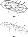
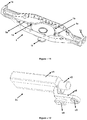
Figure 1 is a perspective view of the spray arrangement according to the present invention. -
Figure 2 is a perspective view of the spray arrangement according to the present invention in a semi-assembled state. -
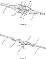
Figure 3 is a perspective view of an intermediate cover of the spray arrangement according to the present invention. -
Figure 4 is a sectional perspective view of the intermediate cover of the spray arrangement according to the present invention. -
Figure 5 is another perspective view of the spray arrangement according to the present invention in a semi-assembled state. -
Figure 6 is a sectional perspective view of the spray arrangement according to the present invention. -
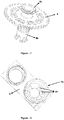
Figure 7 is a perspective view of a fixed gear of the spray arrangement according to the present invention. -
Figure 8 is a perspective view of a movement bearing of the spray arrangement according to the present invention. -
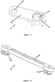
Figure 9 is a perspective view of a first transfer member of the spray arrangement according to the present invention. -
Figure 10 is a perspective view of a second transfer member of the spray arrangement according to the present invention. -
Figure 11 is a perspective view of a main body of the spray arrangement according to the present invention. -
Figure 12 is a perspective view of a movement member of the spray arrangement according to the present invention. -
Figure 13 is a perspective view of a spray member of the spray arrangement according to the present invention. - All the parts illustrated in figures are individually assigned a reference numeral and the corresponding terms of these numbers are listed below:
Main body (1) Holder bearing (1a) First housing (1b) Second housing (1c) Connection member (1d) Movement channel (1e) Liquid inlet (1f) Spray arm (2) Angled hole (2a) Spray member (2b) Movement member (2c) Cover (3) Movement bearing (4) Connection slot (4a) Lug slot (4b) Liquid distribution member (5) Collection portion (5a) Distributing channel (5b) Delivery line (6) Intermediate cover (7) Fixed gear (8) Inlet portion (8a) Fixing portion (8b) First transfer member (9) First transfer body (9a) Movable gear (9b) Fourth connection section (9c) Sixth connection section (9d) Second transfer member (10) Second transfer body (10a) Fifth connection section (10b) Second chamber (c1) Delivery channel (c2) Third connection section (c3) Guide member (c4) Connection body (c5) First chamber (b1) First connection section (b2) - Currently, dishwashers are widely used to clean dishes. Dishwashers comprise a cleaning compartment with quadrilateral section, and dirty dishes are placed at the cleaning compartment via a rack. There is provided at least one spray arrangement in the cleaning compartment, the spray arrangement being located under and/or above the rack and rotating around an axis, preferably along a plane parallel to the base of the rack, so that a cleaning liquid is sprayed onto the dishes. The spray arrangement rotates around said axis with the effect of the liquid sprayed through an angled hole provided on a spray arm thereof and enables the cleaning liquid to reach any possible area within the cleaning compartment. However, due to quadrilateral section of the cleaning compartment, sufficient amount of cleaning liquid cannot be sprayed especially onto corner areas of the cleaning compartment, and the dishes close to those corner areas cannot be cleaned efficiently. Prior art applications for solving said problem accommodate various limitations in terms of usage and/or these applications may cause a severe cost increase and/or remain incapable of cleaning the dishes properly. Within this context, the present invention provides a spray assembly for solving said problems.
- The spray arrangement according to the present invention, as illustrated in
figures 1-13 , is suitable for use in a dishwasher; wherein the dishwasher comprises a cleaning compartment in which the dishes are placed through a rack; such that the spray arrangement is located under and/or above the rack rotatable along a plane parallel to the base of the rack so that a cleaning liquid is sprayed to the dishes, the spray arrangement comprising: at least one main body (1) in the form of a chamber; at least one spray arm (2) which is in connection with a side of the main body (1) and at least a part of which passes through at least one opening provided at said side of the main body (1) so as to extend out of the main body (1), wherein the spray arm (2) has at least one angled hole (a water jet) (2a) thereon, enables the main body (1) (accordingly, itself) to rotate around an axis by spraying the cleaning liquid passing through the spray arm (2) through said angled hole (2a) by means of at least one passage opening provided at the side facing the main body (1) (e.g. facing the center of the main body (1)), moves towards the center of the main body (1) (backward direction) and away from its center (forward direction), and brings into a closed position by moving backwards and into an opened position by moving forwards (in the closed position, part of the spray arm (2) extending out of the opening is the shortest, and in the opened position, part of the spray arm (2) extending out of the opening is the longest); at least one movement mechanism which is preferably located in the main body (1) and provides said movement of the spray arm (2) by transferring rotational movement of the main body (1) to the spray arm (2); and at least one liquid inlet (1f) located at the main body (1), wherein cleaning liquid received from a source is passed through the liquid inlet (1f) and delivered to the spray arm (2) and also to the dishes through holes on spray arm (2). The spray arrangement according to the present invention also comprises at least one holder bearing (1a) which is located above the opening, forms an arch shape above the opening and guides said movement of the spray arm (2), wherein the spray arm (2) is movably fitted at the space between the holder bearing (1a) and the opening; at least one liquid distribution member (5) which can rotate around said axis during the forward-backward movement of the spray arm (2) and has a closed chamber shape in connection with the liquid inlet (1f) from a side thereof, wherein the cleaning liquid from the liquid inlet (1f) is collected in the liquid distribution member (5) and distributed to the spray arm (2); and at least one delivery line (e.g. a hose) (6) which has a flexible form (i.e. it can be bent/folded but does not change in size), is in connection with the passage opening from one side and connected to the liquid distribution member (5) from another side such that the delivery line (6), in the closed position of the spray arm (2), is at an opposite side of the liquid distribution member (5) facing the passage opening (i.e. connected to a side not facing the passage opening), wherein the cleaning liquid received from the liquid inlet (1f) and reaching the liquid distribution member (5) is passed through the delivery line (6) and transferred to the spray arm (2). - In an exemplary embodiment of the spray arrangement according to the present invention, as illustrated in figures, the spray arrangement comprises at least two spray arms (2) located facing each other, and at least two delivery lines (6) each of which is connected to a spray arm (2). During a cleaning process upon operating the dishwasher (e.g. during prewash, main wash and/or rinsing), the cleaning liquid received into the spray arrangement through the liquid inlet (1f) reaches the liquid distribution member (5) and moves to the delivery lines (6) which are connected to the spray arms (2). Then, the cleaning liquid which has moved through the delivery lines (6) reaches the spray arms (2), passes through the spray arms (2) and is sprayed through the holes on the spray arms (2) towards the dishes located in the dishwasher. Spraying the cleaning liquid through angled holes (2a) provided on the spray arms (2) causes the main body (1) to rotate around said axis, and with this rotational movement of the main body (1), the movement mechanism moves the spray arms (2), which are e.g. in the closed position, in the forward direction to bring the spray arms (2) into the opened position (on the contrary, it can also move the spray arms (2), which are in the open position, in the backward direction to ensure that the spray arms (2) is brought into the closed position). With rotational movement of the main body (1), the spray arms (2) lengthen as they approach corner areas of the cleaning compartment (more portion thereof extend out of the main body (1)); and when they are exactly aligned with the corner areas (for example, when they are positioned such that they fit perfectly with the diagonal of the cleaning compartment), they reach the opened position in which the extending part is maximum. The spray arms, which start to move away from the corner area as the main body (1) continues to rotate, move backwards via the movement mechanism, and preferably, when they reach middle of the two successive corner areas, the spray arms (2) will have reached the closed position. As the main body (1) continues to perform its rotational movement, the spray arms (2) in the closed position start to move forwards, and when they are aligned with another corner area, they will have reached the opened position. Therefore, as the main body (1) continues to rotate, the spray arms (2) also move between closed/opened positions, thus the spray arms (2) are enabled to have the longest length when they are aligned with the exact corner areas and have the shortest length when they are aligned with middle areas of the lateral sides, so that dishes inside the cleaning compartment having quadrilateral section can be cleaned efficiently. In addition, movement of spray arms (2) is performed without an external energy (e.g. electric energy), thus avoiding an increase in the energy consumption. However, since movement of spray arms (2) are enabled by rotational movement of main body (1) (i.e. by the thrust of the liquid sprayed through the angled hole (2) and rotating the main body (1)); in order for main body (1) to continue to rotate when the spray arms (2) have the longest length, i.e. in the opened position, it is required that the pressure inside spray arms (2) and delivery lines (6) are overcome and that volume of the spray arrangement is decreased by moving the spray arms (2) backwards. Therefore, a great force is required for this movement and the rotating force of the liquid sprayed through the angled holes (2a) may not be enough to overcome said pressure because liquid pressure inside spray arrangement is greater than the force generating a rotation force and sprayed out of the angled holes (2a). For that reason, the spray arms (2) may be stuck in the longest position, which may cause the main body (1) to be incapable of rotating. With the aim of solving said problem, there are used delivery lines (6) which have a flexible form and a sufficient length in a way not to prevent the movement of the spray arms (2), and the cleaning liquid received from the liquid inlet (1f) is delivered to the spray arms (2) by these delivery lines (6) whose volume remain unchanged. By this way, parts in which the liquid delivery is carried out in the spray arrangement have a constant volume (i.e. the volume of the parts filled with cleaning liquid does not change) and hence the stuck problem can be avoided. In addition, thanks to the spray arrangement according to the invention, additional equipment that require extra space in the cleaning compartment for the movement of spray arms (2) are no longer required, and the spray arrangement can be used efficiently for both the lower rack and the upper rack.
- In an alternative embodiment of the invention, the spray arrangement according to the invention preferably comprises at least one cover (3) which is located between the holder bearings (1a) and covers the main body (1) to form a closed chamber structure with the main body (1). Therefore, movable spray arm (2) and delivery line (6) are prevented from being displaced unintentionally and moving away from the main body (1) during movement.
- In another exemplary embodiment, the spray arrangement preferably comprises at least one movement bearing (4), as illustrated in
figure 8 , which is suitable for fixing to a surface in the cleaning compartment that is immobile during the operation of the dishwasher (e.g. base of the cleaning compartment, base of the rack where the dishes are placed), wherein the movement bearing (4) is connected to the liquid inlet (1f) via at least one connection slot (4a) in such a way as to allow rotational movement of the main body (1), thereby bearing the rotational movement of the main body (1), wherein the axis around which the main body (1) rotates passes through the connection slot (4a). In this embodiment, preferably, a first side of the connection slot (4a) connected to the liquid inlet (1f) and a second side opposite to said first side are open, and the second side is suitable for connecting to a liquid source (e.g. to a liquid collection reservoir of the dishwasher). In this embodiment, preferably, the connection slot (4a) engages with the liquid inlet (1f), and thus, the main body (1) is connected to the movement bearing (4). Cleaning liquid received from the liquid source enters into the connection slot (4) through the opening at the second side, and from there, it passes into the liquid inlet (1). Therefore, the main body (1) is enabled to rotate efficiently such that the liquid inlet is not prevented. - In another preferred embodiment illustrated in
figures 12 and13 , the spray arm (2) comprises at least one spray member (2b), and at least one movement member (2c) which is connected from one side to the spray member (2b) and from an opposite side to the movement mechanism and the delivery line (6). The spray member (2b) comprises at least a first chamber (b1) which is a hollow structure preferably with a quadrilateral section and on which the angled hole (2a) is provided, wherein a first side of the first chamber (b1) is closed and a second side opposite to the first side is opened, and at least a first connection section (b2) preferably in the form of a lug (or a slot) which is located at the second side of the first chamber (b1). The movement member (2c), on the other hand, comprises at least a second chamber (c1) which is a hollow structure preferably with a quadrilateral section and a first side of which is open; at least a second connection section which is preferably in the form of a slot (or a lug), located at the first side of the second chamber (c1), and connected to the first connection section (b2) so that the movement member (2c) is attached to the spray member (2b); at least one delivery channel (c2) which is located at a second side of the second chamber (c1) opposite to the first side thereof and forms the passage opening, wherein the delivery line (6) is connected to the delivery channel (c2); and at least a third connection section (c3) which is preferably in the form of a hole (or a lug), located at the second side of the second chamber (c1) and provides connection to the movement mechanism. Moreover, in this embodiment, there is preferably provided at least one connection body (c5) located at the bottom part of the delivery channel (c2), connected from one end to the second side of the second chamber (c1) and extending towards the center of the main body (1) from another end, wherein the third connection section (c3) is located at a portion of this connection body (c5) extending towards the center of the main body (1). In this embodiment, the spray arrangement also preferably comprises at least one guide member (c4) located at a bottom surface of the connection body (c5) and in the form of a protrusion extending from said bottom surface towards the main body (1), wherein the guide member (c4) is fitted in at least one movement channel (1e) located at the base of the main body (1) and extending in the movement direction of the spray arm (2). Therefore, movement of the spray arm (2) can be determined according to needs by means of the length of the movement channel (1e), and also the spray arm (2) is enabled to move linearly in a proper way. - In another embodiment of the spray arrangement according to the invention, the movement mechanism preferably comprises at least one fixed gear (8), as illustrated in
figure 7 , which is located in the main body (1) preferably in at least a first housing (1b) with a circular section located at the main body (1) (preferably at the center of the main body (1)), such that the fixed gear (8) coincides with rotational axis of the main body (1) and does not rotate with the rotational movement of the main body (1) (e.g. it is fixed with respect to the main body (1)); and at least a first transfer member (9) which provides connection between the spray arm (2) and the fixed gear (8) and thereby transfers the rotational movement of the main body (1) to the spray arm (2). The first transfer member (9) preferably comprises at least a first transfer body (9a) preferably in the form of a rod; at least one movable gear (9b) which is located at a bottom surface of a first side of the first transfer body (9a) and preferably positioned in at least a second housing (1c) at the main body (1) such that the movable gear (9b) is connected to a part of the fixed gear (8) closest to the spray arm (2) and rotates together with the main body (1) around its own axis to move around the fixed gear (8), wherein the second housing (1c) is preferably located at the main body (1) and is connected from one side to the first housing (1b) (i.e. communicates with the first housing (1b); and at least a fourth connection section (9c) preferably in the form of a hole (or a lug) which is located on a second side of the first transfer body (9a) opposite to the first side thereof, and provides connection with the spray arm (2). In this embodiment, the movement arrangement also comprises at least a second transfer member (10) which is rotatably connected from one side to the fourth connection section (9c) and rotatably connected from another side to the spray arm (2), preferably to the third connection section (c3) provided at the movement member (2c). In this embodiment, with rotation of the main body (1), the movable gear (9b) also rotates together with the main body (1) around its own axis because the fixed gear (8) is fixed relative to the main body (1), and with this rotational movement, rotates the first transfer body (9a) connected thereto around the axis the movable gear (9b) rotates. As a result of rotational movement of the first transfer body (9a), the second transfer member (10) rotates, in a plane parallel to the first transfer body (9a), around an axis passing through the fourth connection section (9c). Similarly, the second transfer member (10) rotates in said plane around an axis passing through the portion at which it is connected to the spray arm (2), thus enabling forward-backward movement of the spray arm (2). Therefore, rotational movement of the main body (1) can be transferred to the spray arm (2). The second transfer member (10) preferably comprises at least a second transfer body (10a) in the form of a rod; and at least two fifth connection sections (10b) which are in the form of a lug (or a hole) and are located at the lower surface on opposite sides (preferably on two ends facing each other) of the longitudinal axis of the second transfer body (10a), wherein the second transfer member (10) is connected to the first transfer member (9) (to the fourth connection section (9c)) and to the spray arm (2) (to the third connection section (c3)) so as to rotate around axes passing through the fifth connection sections (10b). In this embodiment, the spray arrangement also preferably comprises at least one connection member (1d) which is located at the base of the main body (1) (preferably in the second housing (1c)) and is in the form of a lug extending upwards from the base of the main body (1), wherein the first transfer member (9) comprises at least a sixth connection section (9d) which is located at the portion where the movable gear (9b) is provided, and is in the form of a through hole comprising the rotational axis of the movable gear (9b), wherein the connection member (1d) is placed in the sixth connection section (9d) and forms rotational axis of the movable gear (9b). In another alternative, the fixed gear (8) preferably comprises at least one hole located substantially at the center thereof; and at least one inlet portion (8a) which is a hollow structure preferably with a cylindrical form, connected to an upper part of the hole and connected from another side to the liquid distribution member (5) such that the liquid distribution member (5) can rotate around the axis around which the main body (1) rotates (preferably communicating with the collection portion (5a)). In this embodiment, the spray arrangement further comprises the movement bearing (4); and a plurality of lug slots (4b) are provided in the connection slot (4a). Moreover, the fixed gear (8) also preferably comprises at least one fixing portion (8b) which is a hollow structure and is connected to a bottom part of the hole thereof, settled at the connection slot (4a), has a plurality of lugs attached to the lug slots (4b), fixes the fixed gear (8) by the lugs settling in the lug slots (4b) and thus prevents the fixed gear (8) from rotating with the rotation of the main body (1). In this embodiment, cleaning liquid received from the liquid source passes from the connection slot (4a) into the fixing portion (8b), from where it reaches the inlet portion (8a) and goes to the liquid distribution member (5). At the same time, the fixed gear (8) is prevented from rotating with respect to the main body (1), and rotational movement of the main body (1) is transferred to the spray arm (2) without requiring an external energy. In this embodiment, distance between two successive lug slots (4b) is greater than distance between the other successive lug slots (4b). Likewise, distance between two successive lugs located in the fixing portion (8b) is greater than distance between the other successive lugs. Therefore, it can be ensured that fixed gear (8) is positioned in the main body (1) properly and the spray arm (2) is the longest and shortest in the correct regions. Furthermore, in this embodiment, among the teeth provided on the fixed gear (8), four teeth with an angle of 45° in between are wider than the other teeth (for example, total width of other two teeth). Accordingly, distance between two successive teeth on the movable gear (9b) is greater than distance between the other successive teeth such that wider teeth on the fixed gear (8) can fit. Thus, it is possible to assemble the fixed gear (8) and the first transfer member (9) correctly such that the spray arm (2) is the longest or shortest in the correct areas. Preferably, the fixed disk (8) is 4 times the size of the movable disk (9b). Therefore, when aligned with the corner areas the spray arm (2) is in the open position in which it is the longest, and when in the middle area between the successive corners, it is in the closed position in which it is the shortest. - In another exemplary embodiment illustrated in
figures 3 and 4 , the spray arrangement preferably comprises at least one intermediate cover (7) which is located at the main body (1) in the bottom part of the delivery line (6), wherein the liquid distribution member (5) is located at the intermediate cover (7). Thanks to the intermediate cover (7) preferably in the form of a grid, the flexible delivery line (6) can be prevented from contacting other parts of the main body (1) while moving by the movement of the spray arm (2), thus the delivery line (6) and the other parts can be more durable. - Thanks to the spray arrangement according to the present invention, cleaning liquid can be effectively delivered to a major part of the inner volume of the cleaning compartment, and dishes can be cleaned more efficiently and efficiently. Further, extendable/retractable spray arm (2) is moved without using an external energy such as electricity; and the stuck problem that may occur while the spray arm (2), which is in the opened position during this movement, switches to the closed position can be solved in a simple and practical way by using the flexible delivery line (6). Therefore, an easy to use, cost-effective, practical and reliable spray arrangement can be achieved.
Claims (15)
- A spray arrangement which is suitable for use in a dishwasher; wherein the dishwasher comprises a cleaning compartment in which the dishes are placed through a rack; such that the spray arrangement is located under and/or above the rack rotatable along a plane parallel to the base of the rack so that a cleaning liquid is sprayed to the dishes, and which comprises:• at least one main body (1) in the form of a chamber;• at least one spray arm (2) which is in connection with a side of the main body (1) and at least a part of which passes through at least one opening provided at said side of the main body (1) so as to extend out of the main body (1), wherein the spray arm (2) has at least one angled hole (2a) thereon, enables the main body (1) to rotate around an axis by spraying the cleaning liquid passing through the spray arm (2) through said angled hole (2a) by means of at least one passage opening provided at the side facing the main body (1), moves backward and forward towards the center of the main body (1) and away from its center, and brings into a closed position by moving backwards and into an opened position by moving forwards;• at least one movement mechanism which provides said movement of the spray arm (2) by transferring rotational movement of the main body (1) to the spray arm (2);• at least one liquid inlet (1f) located at the main body (1), wherein cleaning liquid received from a source is passed through the liquid inlet (1f) and delivered to the spray arm (2) and also to the dishes through holes on spray arm (2);
the spray arrangement characterized by comprising:• at least one holder bearing (1a) which is located above the opening, forms an arch shape above the opening and guides said movement of the spray arm (2), wherein the spray arm (2) is movably fitted at the space between the holder bearing (1a) and the opening;• at least one liquid distribution member (5) which can rotate around said axis during the forward-backward movement of the spray arm (2) and has a closed chamber shape in connection with the liquid inlet (1f) from a side thereof, wherein the cleaning liquid from the liquid inlet (1f) is collected in the liquid distribution member (5) and distributed to the spray arm (2); and• at least one delivery line (6) which has a flexible form, is in connection with the passage opening from one side and connected to the liquid distribution member (5) from another side such that the delivery line (6), in the closed position of the spray arm (2), is at an opposite side of the liquid distribution member (5) facing the passage opening, wherein the cleaning liquid received from the liquid inlet (1f) and reaching the liquid distribution member (5) is passed through the delivery line (6) and transferred to the spray arm (2). - A spray arrangement according to claim 1, characterized in that the movement mechanism is located in the main body (1).
- A spray arrangement according to claim 1, characterized in that the delivery line (6) is a hose.
- A spray arrangement according to claim 1, characterized in that the spray arrangement comprises at least one cover (3) which is located between the holder bearings (1a) and covers the main body (1) to form a closed chamber structure with the main body (1).
- A spray arrangement according to claim 1, characterized in that the spray arrangement comprises at least one movement bearing (4) which is suitable for fixing to a surface in the cleaning compartment that is immobile during the operation of the dishwasher, wherein the movement bearing (4) is connected to the liquid inlet (1f) via at least one connection slot (4a) in such a way as to allow rotational movement of the main body (1), thereby bearing the rotational movement of the main body (1), wherein a first side of the connection slot (4a) connected to the liquid inlet (1f) and a second side opposite to said first side are open, and the second side is connected to a liquid source.
- A spray arrangement according to claim 1, characterized in that the spray arm (2) comprises:• at least one spray member (2b) which comprises at least a first chamber (b1) which is a hollow structure and on which the angled hole (2a) is provided, wherein a first side of the first chamber (b1) is closed and a second side opposite to the first side is open, and at least a first connection section (b2) which is located at the second side of the first chamber (b1); and• at least one movement member (2c) which is connected from one side to the spray member (2b) and from an opposite side to the movement mechanism and the delivery line (6), the movement member (2c) comprising:at least a second chamber (c1) which is a hollow structure and a first side of which is open; at least a second connection section which is located at the first side of the second chamber (c1), and connected to the first connection section (b2) so that the movement member (2c) is attached to the spray member (2b);at least one delivery channel (c2) which is located at a second side of the second chamber (c1) opposite to the first side thereof and forms the passage opening, wherein the delivery line (6) is connected to the delivery channel (c2); and at least a third connection section (c3) which is located at the second side of the second chamber (c1) and provides connection to the movement mechanism.
- A spray arrangement according to claim 6, characterized in that the spray arrangement comprises at least one connection body (c5) located at the bottom part of the delivery channel (c2), connected from one end to the second side of the second chamber (c1) and extending towards the center of the main body (1) from another end, wherein the third connection section (c3) is located at a portion of the connection body (c5) extending towards the center of the main body (1); at least one guide member (c4) located at a bottom surface of the connection body (c5) and in the form of a protrusion extending from said bottom surface towards the main body (1); and at least one movement channel (1e) in which the guide member (c4) is fitted and which is located at the base of the main body (1) and extends in the movement direction of the spray arm (2).
- A spray arrangement according to any of the preceding claims, characterized in that the movement mechanism comprises:• at least one fixed gear (8) which is provided in the main body (1) such that the fixed gear (8) coincides with rotational axis of the main body (1) and does not rotate with the rotational movement of the main body (1), the fixed gear (8) being located in at least a first housing (1b) with a circular section, which is provided at the main body (1);• at least a first transfer member (9) which provides connection between the spray arm (2) and the fixed gear (8) and thereby transfers the rotational movement of the main body (1) to the spray arm (2); and• at least a second transfer member (10) which is rotatably connected from one side to the fourth connection section (9c) and rotatably connected from another side to the spray arm (2).
- A spray arrangement according to claim 8, characterized in that the first transfer member (9) comprises:• at least a first transfer body (9a);• at least one movable gear (9b) which is located at a bottom surface of a first side of the first transfer body (9a) and positioned at the main body (1) such that the movable gear (9b) is connected to a part of the fixed gear (8) closest to the spray arm (2) and rotates together with the main body (1) around its own axis to move around the fixed gear (8), wherein the movable gear (9b) is provided in at least a second housing (1c) which is located at the main body (1) and is connected from one side to the first housing (1b); and• at least a fourth connection section (9c) which is located on a second side of the first transfer body (9a) opposite to the first side thereof, and provides connection with the spray arm (2).
- A spray arrangement according to claim 8, characterized in that the second transfer member (10) comprises at least a second transfer body (10a) in the form of a rod, and at least two fifth connection sections (10b) which are located at the lower surface on opposite sides of the longitudinal axis of the second transfer body (10a), and that the second transfer member (10) is connected to the first transfer member (9) and the spray arm (2) so as to rotate around axes passing through the fifth connection sections (10b).
- A spray arrangement according to claim 9 or 10, characterized in that the spray arrangement comprises at least one connection member (1d) which is in the form of a lug extending upwards from the base of the main body (1), located at the base of the main body (1), and positioned in a second housing (1c) which is located at the main body (9) and in which the movable gear (9b) is provided; and that the first transfer member (9) comprises at least a sixth connection section (9d) which is located at the portion where the movable gear (9b) is provided and is in the form of a through hole comprising the rotational axis of the movable gear (9b), wherein the connection member (1d) is placed in the sixth connection section (9d) and forms rotational axis of the movable gear (9b).
- A spray arrangement according to any of the claims 8 to 11, characterized in that:• the fixed gear (8) comprises at least one hole located substantially at the center thereof; at least one inlet portion (8a) which is a hollow structure, connected to an upper part of the hole and connected from another side to the liquid distribution member (5) such that the liquid distribution member (5) can rotate around the axis around which the main body (1) rotates;• the spray arrangement comprises at least one movement bearing (4) which is suitable for fixing to a surface in the cleaning compartment that is immobile during the operation of the dishwasher, wherein the movement bearing (4) is connected to the liquid inlet (1f) via at least one connection slot (4a) in such a way as to allow rotational movement of the main body (1), thereby bearing the rotational movement of the main body (1), wherein a plurality of lug slots (4b) are provided in the connection slot (4a); and• the fixed gear (8) also comprises at least one fixing portion (8b) which is a hollow structure and is connected to a bottom part of the hole thereof, fitted at the connection slot (4a), has a plurality of lugs attached to the lug slots (4b), fixes the fixed gear (8) by the lugs settling in the lug slots (4b) and thus prevents the fixed gear (8) from rotating with the rotation of the main body (1).
- A spray arrangement according to claim 12, characterized in that distance between two successive lug slots (4b) is greater than distance between the other successive lug slots (4b) and distance between two successive lugs located in the fixing portion (8b) is greater than distance between the other successive lugs.
- A spray arrangement according to claim 9 or 13, characterized in that four teeth, among the teeth provided on the fixed gear (8), with an angle of 45° in between are wider than the other teeth, and distance between two successive teeth on the movable gear (9b) is greater than distance between the other teeth such that wider teeth on the fixed gear (8) can fit.
- A spray arrangement according to any of the preceding claims, characterized in that the spray arrangement comprises at least one intermediate cover (7) which is located at the main body (1) in the bottom part of the delivery line (6), wherein the liquid distribution member (5) is located at the intermediate cover (7).
Applications Claiming Priority (1)
| Application Number | Priority Date | Filing Date | Title |
|---|---|---|---|
| TR2019/10146A TR201910146A2 (en) | 2019-07-08 | 2019-07-08 | A fountain assembly for dishwashers. |
Publications (2)
| Publication Number | Publication Date |
|---|---|
| EP3766400A1 true EP3766400A1 (en) | 2021-01-20 |
| EP3766400B1 EP3766400B1 (en) | 2023-09-06 |
Family
ID=71579510
Family Applications (1)
| Application Number | Title | Priority Date | Filing Date |
|---|---|---|---|
| EP20183623.6A Active EP3766400B1 (en) | 2019-07-08 | 2020-07-02 | A spray arrangement for dishwashers |
Country Status (3)
| Country | Link |
|---|---|
| US (1) | US11179019B2 (en) |
| EP (1) | EP3766400B1 (en) |
| TR (1) | TR201910146A2 (en) |
Families Citing this family (9)
| Publication number | Priority date | Publication date | Assignee | Title |
|---|---|---|---|---|
| CN111345761A (en) * | 2018-12-20 | 2020-06-30 | 惠而浦公司 | Dish washing machine |
| US11375874B2 (en) | 2020-03-30 | 2022-07-05 | Whirlpool Corporation | Dishwasher with a dish rack and utensil caddy |
| CN113907684B (en) * | 2021-09-28 | 2023-06-27 | 追觅创新科技(苏州)有限公司 | Spray set and cleaning equipment |
| CN114668358B (en) * | 2022-05-05 | 2025-06-03 | 珠海格力电器股份有限公司 | Spray arm and dish washer |
| TR2022010887A1 (en) * | 2022-06-30 | 2024-01-22 | Arcelik As | A DISHWASHER WITH A CUSTOMIZED SPRAY ELEMENT |
| CN115040048B (en) * | 2022-07-04 | 2026-03-03 | 杭州老板电器股份有限公司 | Spray disk device and cleaning equipment |
| CN116098553B (en) * | 2023-02-27 | 2025-09-26 | 华帝股份有限公司 | Spray arm device of dishwasher |
| CN116530907A (en) * | 2023-06-12 | 2023-08-04 | 广东慧曼智能科技有限公司 | Telescopic spray arm structure of dish washer |
| CN118557111B (en) * | 2024-07-31 | 2024-10-11 | 杭州老板电器股份有限公司 | Cleaning Machine |
Citations (5)
| Publication number | Priority date | Publication date | Assignee | Title |
|---|---|---|---|---|
| DE1628755A1 (en) * | 1966-05-17 | 1971-01-28 | Philips Patentverwaltung | Dishwasher with spray arms arranged between the dish racks in the washing area |
| US5842492A (en) | 1996-06-14 | 1998-12-01 | Daewoo Electronics Co., Ltd. | Apparatus for dispersing washing water of a dishwasher |
| CN104814710A (en) * | 2015-05-26 | 2015-08-05 | 佛山市顺德区美的洗涤电器制造有限公司 | Gushing arm component and dish washing machine provided with same |
| EP3378370A1 (en) * | 2017-03-21 | 2018-09-26 | Candy S.p.A. | Dishwasher with rotary-translating spraying arm |
| CN105286752B (en) * | 2015-11-20 | 2018-10-26 | 佛山市顺德区美的洗涤电器制造有限公司 | For the gushing arm component of dish-washing machine and with its dish-washing machine |
Family Cites Families (1)
| Publication number | Priority date | Publication date | Assignee | Title |
|---|---|---|---|---|
| DE102010051218A1 (en) * | 2010-11-12 | 2012-05-16 | Belimed Ag | Washing arm for a cleaning machine for cleaning medical, pharmaceutical and / or laboratory utensils |
-
2019
- 2019-07-08 TR TR2019/10146A patent/TR201910146A2/en unknown
-
2020
- 2020-07-02 EP EP20183623.6A patent/EP3766400B1/en active Active
- 2020-07-07 US US16/922,312 patent/US11179019B2/en not_active Expired - Fee Related
Patent Citations (5)
| Publication number | Priority date | Publication date | Assignee | Title |
|---|---|---|---|---|
| DE1628755A1 (en) * | 1966-05-17 | 1971-01-28 | Philips Patentverwaltung | Dishwasher with spray arms arranged between the dish racks in the washing area |
| US5842492A (en) | 1996-06-14 | 1998-12-01 | Daewoo Electronics Co., Ltd. | Apparatus for dispersing washing water of a dishwasher |
| CN104814710A (en) * | 2015-05-26 | 2015-08-05 | 佛山市顺德区美的洗涤电器制造有限公司 | Gushing arm component and dish washing machine provided with same |
| CN105286752B (en) * | 2015-11-20 | 2018-10-26 | 佛山市顺德区美的洗涤电器制造有限公司 | For the gushing arm component of dish-washing machine and with its dish-washing machine |
| EP3378370A1 (en) * | 2017-03-21 | 2018-09-26 | Candy S.p.A. | Dishwasher with rotary-translating spraying arm |
Also Published As
| Publication number | Publication date |
|---|---|
| US11179019B2 (en) | 2021-11-23 |
| US20210007573A1 (en) | 2021-01-14 |
| EP3766400B1 (en) | 2023-09-06 |
| TR201910146A2 (en) | 2021-01-21 |
Similar Documents
| Publication | Publication Date | Title |
|---|---|---|
| EP3766400B1 (en) | A spray arrangement for dishwashers | |
| EP3900605B1 (en) | Dish-washing machine and spraying mechanism | |
| US9386903B2 (en) | Dishwasher with spray system | |
| US7980260B2 (en) | Dishwasher with driven rotatable spray arm | |
| US5842492A (en) | Apparatus for dispersing washing water of a dishwasher | |
| EP3703544B1 (en) | Fan-shaped spray detergent nozzle | |
| US20200281441A1 (en) | Supporting device and dish washer having the same | |
| US7754024B2 (en) | Crockery basket for a dishwasher machine, comprising an intensive washing zone | |
| US9173541B2 (en) | Dishwashing machine | |
| US20190053686A1 (en) | Pre-drying device for a dishwasher | |
| CN112672669A (en) | Dishwasher with docking device for a lifting rack | |
| EP1277430A1 (en) | Dishwasher with variable washing liquid distribution | |
| US10687684B2 (en) | Dishwasher with tine sprayer rings | |
| EP2185053B1 (en) | A dishwasher | |
| US11510547B2 (en) | Sprinkler device for dishwashers | |
| US20150136189A1 (en) | Sliding spray arm assembly for a dishwashing appliance | |
| DE102010032005A1 (en) | Quadratic dishwasher, has large spray arm moved around rotational axis, and small spray arm whose movements stand independence of movements of large spray arm, where small spray arm covers entire area of base surface of dishwasher | |
| KR100258614B1 (en) | Dishwasher | |
| EP3593697B1 (en) | Cutlery basket for dishwashers | |
| KR100258616B1 (en) | Dishwasher | |
| EP3796826B1 (en) | A dishwasher comprising spray arm | |
| KR100258617B1 (en) | Dishwasher | |
| US12458204B2 (en) | Locating clip for a bottle washer assembly of a dishwasher appliance | |
| JPS645579Y2 (en) | ||
| US20210378481A1 (en) | Scrubbing mechanism and scrubbing pad |
Legal Events
| Date | Code | Title | Description |
|---|---|---|---|
| PUAI | Public reference made under article 153(3) epc to a published international application that has entered the european phase |
Free format text: ORIGINAL CODE: 0009012 |
|
| STAA | Information on the status of an ep patent application or granted ep patent |
Free format text: STATUS: THE APPLICATION HAS BEEN PUBLISHED |
|
| AK | Designated contracting states |
Kind code of ref document: A1 Designated state(s): AL AT BE BG CH CY CZ DE DK EE ES FI FR GB GR HR HU IE IS IT LI LT LU LV MC MK MT NL NO PL PT RO RS SE SI SK SM TR |
|
| AX | Request for extension of the european patent |
Extension state: BA ME |
|
| STAA | Information on the status of an ep patent application or granted ep patent |
Free format text: STATUS: REQUEST FOR EXAMINATION WAS MADE |
|
| 17P | Request for examination filed |
Effective date: 20210701 |
|
| RBV | Designated contracting states (corrected) |
Designated state(s): AL AT BE BG CH CY CZ DE DK EE ES FI FR GB GR HR HU IE IS IT LI LT LU LV MC MK MT NL NO PL PT RO RS SE SI SK SM TR |
|
| GRAP | Despatch of communication of intention to grant a patent |
Free format text: ORIGINAL CODE: EPIDOSNIGR1 |
|
| STAA | Information on the status of an ep patent application or granted ep patent |
Free format text: STATUS: GRANT OF PATENT IS INTENDED |
|
| RIC1 | Information provided on ipc code assigned before grant |
Ipc: A47L 15/23 20060101AFI20230306BHEP |
|
| INTG | Intention to grant announced |
Effective date: 20230404 |
|
| GRAS | Grant fee paid |
Free format text: ORIGINAL CODE: EPIDOSNIGR3 |
|
| GRAA | (expected) grant |
Free format text: ORIGINAL CODE: 0009210 |
|
| STAA | Information on the status of an ep patent application or granted ep patent |
Free format text: STATUS: THE PATENT HAS BEEN GRANTED |
|
| AK | Designated contracting states |
Kind code of ref document: B1 Designated state(s): AL AT BE BG CH CY CZ DE DK EE ES FI FR GB GR HR HU IE IS IT LI LT LU LV MC MK MT NL NO PL PT RO RS SE SI SK SM TR |
|
| REG | Reference to a national code |
Ref country code: GB Ref legal event code: FG4D |
|
| REG | Reference to a national code |
Ref country code: CH Ref legal event code: EP |
|
| REG | Reference to a national code |
Ref country code: IE Ref legal event code: FG4D |
|
| REG | Reference to a national code |
Ref country code: DE Ref legal event code: R096 Ref document number: 602020017065 Country of ref document: DE |
|
| REG | Reference to a national code |
Ref country code: LT Ref legal event code: MG9D |
|
| REG | Reference to a national code |
Ref country code: NL Ref legal event code: MP Effective date: 20230906 |
|
| PG25 | Lapsed in a contracting state [announced via postgrant information from national office to epo] |
Ref country code: GR Free format text: LAPSE BECAUSE OF FAILURE TO SUBMIT A TRANSLATION OF THE DESCRIPTION OR TO PAY THE FEE WITHIN THE PRESCRIBED TIME-LIMIT Effective date: 20231207 |
|
| PG25 | Lapsed in a contracting state [announced via postgrant information from national office to epo] |
Ref country code: SE Free format text: LAPSE BECAUSE OF FAILURE TO SUBMIT A TRANSLATION OF THE DESCRIPTION OR TO PAY THE FEE WITHIN THE PRESCRIBED TIME-LIMIT Effective date: 20230906 Ref country code: RS Free format text: LAPSE BECAUSE OF FAILURE TO SUBMIT A TRANSLATION OF THE DESCRIPTION OR TO PAY THE FEE WITHIN THE PRESCRIBED TIME-LIMIT Effective date: 20230906 Ref country code: NO Free format text: LAPSE BECAUSE OF FAILURE TO SUBMIT A TRANSLATION OF THE DESCRIPTION OR TO PAY THE FEE WITHIN THE PRESCRIBED TIME-LIMIT Effective date: 20231206 Ref country code: LV Free format text: LAPSE BECAUSE OF FAILURE TO SUBMIT A TRANSLATION OF THE DESCRIPTION OR TO PAY THE FEE WITHIN THE PRESCRIBED TIME-LIMIT Effective date: 20230906 Ref country code: LT Free format text: LAPSE BECAUSE OF FAILURE TO SUBMIT A TRANSLATION OF THE DESCRIPTION OR TO PAY THE FEE WITHIN THE PRESCRIBED TIME-LIMIT Effective date: 20230906 Ref country code: HR Free format text: LAPSE BECAUSE OF FAILURE TO SUBMIT A TRANSLATION OF THE DESCRIPTION OR TO PAY THE FEE WITHIN THE PRESCRIBED TIME-LIMIT Effective date: 20230906 Ref country code: GR Free format text: LAPSE BECAUSE OF FAILURE TO SUBMIT A TRANSLATION OF THE DESCRIPTION OR TO PAY THE FEE WITHIN THE PRESCRIBED TIME-LIMIT Effective date: 20231207 Ref country code: FI Free format text: LAPSE BECAUSE OF FAILURE TO SUBMIT A TRANSLATION OF THE DESCRIPTION OR TO PAY THE FEE WITHIN THE PRESCRIBED TIME-LIMIT Effective date: 20230906 |
|
| REG | Reference to a national code |
Ref country code: AT Ref legal event code: MK05 Ref document number: 1607366 Country of ref document: AT Kind code of ref document: T Effective date: 20230906 |
|
| PG25 | Lapsed in a contracting state [announced via postgrant information from national office to epo] |
Ref country code: NL Free format text: LAPSE BECAUSE OF FAILURE TO SUBMIT A TRANSLATION OF THE DESCRIPTION OR TO PAY THE FEE WITHIN THE PRESCRIBED TIME-LIMIT Effective date: 20230906 |
|
| PG25 | Lapsed in a contracting state [announced via postgrant information from national office to epo] |
Ref country code: IS Free format text: LAPSE BECAUSE OF FAILURE TO SUBMIT A TRANSLATION OF THE DESCRIPTION OR TO PAY THE FEE WITHIN THE PRESCRIBED TIME-LIMIT Effective date: 20240106 |
|
| PG25 | Lapsed in a contracting state [announced via postgrant information from national office to epo] |
Ref country code: AT Free format text: LAPSE BECAUSE OF FAILURE TO SUBMIT A TRANSLATION OF THE DESCRIPTION OR TO PAY THE FEE WITHIN THE PRESCRIBED TIME-LIMIT Effective date: 20230906 |
|
| PG25 | Lapsed in a contracting state [announced via postgrant information from national office to epo] |
Ref country code: ES Free format text: LAPSE BECAUSE OF FAILURE TO SUBMIT A TRANSLATION OF THE DESCRIPTION OR TO PAY THE FEE WITHIN THE PRESCRIBED TIME-LIMIT Effective date: 20230906 |
|
| PG25 | Lapsed in a contracting state [announced via postgrant information from national office to epo] |
Ref country code: SM Free format text: LAPSE BECAUSE OF FAILURE TO SUBMIT A TRANSLATION OF THE DESCRIPTION OR TO PAY THE FEE WITHIN THE PRESCRIBED TIME-LIMIT Effective date: 20230906 Ref country code: RO Free format text: LAPSE BECAUSE OF FAILURE TO SUBMIT A TRANSLATION OF THE DESCRIPTION OR TO PAY THE FEE WITHIN THE PRESCRIBED TIME-LIMIT Effective date: 20230906 Ref country code: IS Free format text: LAPSE BECAUSE OF FAILURE TO SUBMIT A TRANSLATION OF THE DESCRIPTION OR TO PAY THE FEE WITHIN THE PRESCRIBED TIME-LIMIT Effective date: 20240106 Ref country code: ES Free format text: LAPSE BECAUSE OF FAILURE TO SUBMIT A TRANSLATION OF THE DESCRIPTION OR TO PAY THE FEE WITHIN THE PRESCRIBED TIME-LIMIT Effective date: 20230906 Ref country code: EE Free format text: LAPSE BECAUSE OF FAILURE TO SUBMIT A TRANSLATION OF THE DESCRIPTION OR TO PAY THE FEE WITHIN THE PRESCRIBED TIME-LIMIT Effective date: 20230906 Ref country code: CZ Free format text: LAPSE BECAUSE OF FAILURE TO SUBMIT A TRANSLATION OF THE DESCRIPTION OR TO PAY THE FEE WITHIN THE PRESCRIBED TIME-LIMIT Effective date: 20230906 Ref country code: AT Free format text: LAPSE BECAUSE OF FAILURE TO SUBMIT A TRANSLATION OF THE DESCRIPTION OR TO PAY THE FEE WITHIN THE PRESCRIBED TIME-LIMIT Effective date: 20230906 Ref country code: PT Free format text: LAPSE BECAUSE OF FAILURE TO SUBMIT A TRANSLATION OF THE DESCRIPTION OR TO PAY THE FEE WITHIN THE PRESCRIBED TIME-LIMIT Effective date: 20240108 Ref country code: SK Free format text: LAPSE BECAUSE OF FAILURE TO SUBMIT A TRANSLATION OF THE DESCRIPTION OR TO PAY THE FEE WITHIN THE PRESCRIBED TIME-LIMIT Effective date: 20230906 |
|
| PG25 | Lapsed in a contracting state [announced via postgrant information from national office to epo] |
Ref country code: PL Free format text: LAPSE BECAUSE OF FAILURE TO SUBMIT A TRANSLATION OF THE DESCRIPTION OR TO PAY THE FEE WITHIN THE PRESCRIBED TIME-LIMIT Effective date: 20230906 Ref country code: IT Free format text: LAPSE BECAUSE OF FAILURE TO SUBMIT A TRANSLATION OF THE DESCRIPTION OR TO PAY THE FEE WITHIN THE PRESCRIBED TIME-LIMIT Effective date: 20230906 |
|
| REG | Reference to a national code |
Ref country code: DE Ref legal event code: R097 Ref document number: 602020017065 Country of ref document: DE |
|
| PG25 | Lapsed in a contracting state [announced via postgrant information from national office to epo] |
Ref country code: DK Free format text: LAPSE BECAUSE OF FAILURE TO SUBMIT A TRANSLATION OF THE DESCRIPTION OR TO PAY THE FEE WITHIN THE PRESCRIBED TIME-LIMIT Effective date: 20230906 |
|
| PLBE | No opposition filed within time limit |
Free format text: ORIGINAL CODE: 0009261 |
|
| STAA | Information on the status of an ep patent application or granted ep patent |
Free format text: STATUS: NO OPPOSITION FILED WITHIN TIME LIMIT |
|
| PG25 | Lapsed in a contracting state [announced via postgrant information from national office to epo] |
Ref country code: DK Free format text: LAPSE BECAUSE OF FAILURE TO SUBMIT A TRANSLATION OF THE DESCRIPTION OR TO PAY THE FEE WITHIN THE PRESCRIBED TIME-LIMIT Effective date: 20230906 Ref country code: SI Free format text: LAPSE BECAUSE OF FAILURE TO SUBMIT A TRANSLATION OF THE DESCRIPTION OR TO PAY THE FEE WITHIN THE PRESCRIBED TIME-LIMIT Effective date: 20230906 |
|
| 26N | No opposition filed |
Effective date: 20240607 |
|
| PGFP | Annual fee paid to national office [announced via postgrant information from national office to epo] |
Ref country code: DE Payment date: 20240719 Year of fee payment: 5 |
|
| PGFP | Annual fee paid to national office [announced via postgrant information from national office to epo] |
Ref country code: GB Payment date: 20240725 Year of fee payment: 5 |
|
| PG25 | Lapsed in a contracting state [announced via postgrant information from national office to epo] |
Ref country code: BG Free format text: LAPSE BECAUSE OF FAILURE TO SUBMIT A TRANSLATION OF THE DESCRIPTION OR TO PAY THE FEE WITHIN THE PRESCRIBED TIME-LIMIT Effective date: 20230906 |
|
| PG25 | Lapsed in a contracting state [announced via postgrant information from national office to epo] |
Ref country code: BG Free format text: LAPSE BECAUSE OF FAILURE TO SUBMIT A TRANSLATION OF THE DESCRIPTION OR TO PAY THE FEE WITHIN THE PRESCRIBED TIME-LIMIT Effective date: 20230906 |
|
| PG25 | Lapsed in a contracting state [announced via postgrant information from national office to epo] |
Ref country code: MC Free format text: LAPSE BECAUSE OF FAILURE TO SUBMIT A TRANSLATION OF THE DESCRIPTION OR TO PAY THE FEE WITHIN THE PRESCRIBED TIME-LIMIT Effective date: 20230906 |
|
| REG | Reference to a national code |
Ref country code: CH Ref legal event code: PL |
|
| PG25 | Lapsed in a contracting state [announced via postgrant information from national office to epo] |
Ref country code: LU Free format text: LAPSE BECAUSE OF NON-PAYMENT OF DUE FEES Effective date: 20240702 |
|
| PG25 | Lapsed in a contracting state [announced via postgrant information from national office to epo] |
Ref country code: LU Free format text: LAPSE BECAUSE OF NON-PAYMENT OF DUE FEES Effective date: 20240702 |
|
| PG25 | Lapsed in a contracting state [announced via postgrant information from national office to epo] |
Ref country code: CH Free format text: LAPSE BECAUSE OF NON-PAYMENT OF DUE FEES Effective date: 20240731 Ref country code: BE Free format text: LAPSE BECAUSE OF NON-PAYMENT OF DUE FEES Effective date: 20240731 |
|
| PG25 | Lapsed in a contracting state [announced via postgrant information from national office to epo] |
Ref country code: FR Free format text: LAPSE BECAUSE OF NON-PAYMENT OF DUE FEES Effective date: 20240731 |
|
| REG | Reference to a national code |
Ref country code: BE Ref legal event code: MM Effective date: 20240731 |
|
| PG25 | Lapsed in a contracting state [announced via postgrant information from national office to epo] |
Ref country code: IE Free format text: LAPSE BECAUSE OF NON-PAYMENT OF DUE FEES Effective date: 20240702 |
|
| PG25 | Lapsed in a contracting state [announced via postgrant information from national office to epo] |
Ref country code: CY Free format text: LAPSE BECAUSE OF FAILURE TO SUBMIT A TRANSLATION OF THE DESCRIPTION OR TO PAY THE FEE WITHIN THE PRESCRIBED TIME-LIMIT; INVALID AB INITIO Effective date: 20200702 |
|
| REG | Reference to a national code |
Ref country code: DE Ref legal event code: R119 Ref document number: 602020017065 Country of ref document: DE |
|
| PG25 | Lapsed in a contracting state [announced via postgrant information from national office to epo] |
Ref country code: HU Free format text: LAPSE BECAUSE OF FAILURE TO SUBMIT A TRANSLATION OF THE DESCRIPTION OR TO PAY THE FEE WITHIN THE PRESCRIBED TIME-LIMIT; INVALID AB INITIO Effective date: 20200702 |
|
| GBPC | Gb: european patent ceased through non-payment of renewal fee |
Effective date: 20250702 |
|
| PG25 | Lapsed in a contracting state [announced via postgrant information from national office to epo] |
Ref country code: GB Free format text: LAPSE BECAUSE OF NON-PAYMENT OF DUE FEES Effective date: 20250702 |
|
| PG25 | Lapsed in a contracting state [announced via postgrant information from national office to epo] |
Ref country code: DE Free format text: LAPSE BECAUSE OF NON-PAYMENT OF DUE FEES Effective date: 20260203 |