EP3766302B1 - Portable autonomous vehicle connectivity platform - Google Patents
Portable autonomous vehicle connectivity platform Download PDFInfo
- Publication number
- EP3766302B1 EP3766302B1 EP19713611.2A EP19713611A EP3766302B1 EP 3766302 B1 EP3766302 B1 EP 3766302B1 EP 19713611 A EP19713611 A EP 19713611A EP 3766302 B1 EP3766302 B1 EP 3766302B1
- Authority
- EP
- European Patent Office
- Prior art keywords
- autonomous vehicle
- portable
- connectivity platform
- vehicle connectivity
- mission
- Prior art date
- Legal status (The legal status is an assumption and is not a legal conclusion. Google has not performed a legal analysis and makes no representation as to the accuracy of the status listed.)
- Active
Links
Images




Classifications
-
- H—ELECTRICITY
- H04—ELECTRIC COMMUNICATION TECHNIQUE
- H04W—WIRELESS COMMUNICATION NETWORKS
- H04W24/00—Supervisory, monitoring or testing arrangements
- H04W24/10—Scheduling measurement reports ; Arrangements for measurement reports
-
- G—PHYSICS
- G08—SIGNALLING
- G08G—TRAFFIC CONTROL SYSTEMS
- G08G5/00—Traffic control systems for aircraft
- G08G5/20—Arrangements for acquiring, generating, sharing or displaying traffic information
-
- G—PHYSICS
- G08—SIGNALLING
- G08G—TRAFFIC CONTROL SYSTEMS
- G08G5/00—Traffic control systems for aircraft
- G08G5/20—Arrangements for acquiring, generating, sharing or displaying traffic information
- G08G5/22—Arrangements for acquiring, generating, sharing or displaying traffic information located on the ground
-
- G—PHYSICS
- G08—SIGNALLING
- G08G—TRAFFIC CONTROL SYSTEMS
- G08G5/00—Traffic control systems for aircraft
- G08G5/20—Arrangements for acquiring, generating, sharing or displaying traffic information
- G08G5/26—Transmission of traffic-related information between aircraft and ground stations
-
- G—PHYSICS
- G08—SIGNALLING
- G08G—TRAFFIC CONTROL SYSTEMS
- G08G5/00—Traffic control systems for aircraft
- G08G5/30—Flight plan management
- G08G5/32—Flight plan management for flight plan preparation
-
- G—PHYSICS
- G08—SIGNALLING
- G08G—TRAFFIC CONTROL SYSTEMS
- G08G5/00—Traffic control systems for aircraft
- G08G5/50—Navigation or guidance aids
- G08G5/55—Navigation or guidance aids for a single aircraft
-
- G—PHYSICS
- G08—SIGNALLING
- G08G—TRAFFIC CONTROL SYSTEMS
- G08G5/00—Traffic control systems for aircraft
- G08G5/50—Navigation or guidance aids
- G08G5/57—Navigation or guidance aids for unmanned aircraft
-
- H—ELECTRICITY
- H04—ELECTRIC COMMUNICATION TECHNIQUE
- H04B—TRANSMISSION
- H04B7/00—Radio transmission systems, i.e. using radiation field
- H04B7/14—Relay systems
- H04B7/15—Active relay systems
- H04B7/185—Space-based or airborne stations; Stations for satellite systems
- H04B7/18502—Airborne stations
- H04B7/18504—Aircraft used as relay or high altitude atmospheric platform
-
- H—ELECTRICITY
- H04—ELECTRIC COMMUNICATION TECHNIQUE
- H04W—WIRELESS COMMUNICATION NETWORKS
- H04W76/00—Connection management
- H04W76/10—Connection setup
-
- H—ELECTRICITY
- H04—ELECTRIC COMMUNICATION TECHNIQUE
- H04W—WIRELESS COMMUNICATION NETWORKS
- H04W84/00—Network topologies
- H04W84/005—Moving wireless networks
-
- H—ELECTRICITY
- H04—ELECTRIC COMMUNICATION TECHNIQUE
- H04W—WIRELESS COMMUNICATION NETWORKS
- H04W88/00—Devices specially adapted for wireless communication networks, e.g. terminals, base stations or access point devices
- H04W88/08—Access point devices
-
- B—PERFORMING OPERATIONS; TRANSPORTING
- B64—AIRCRAFT; AVIATION; COSMONAUTICS
- B64U—UNMANNED AERIAL VEHICLES [UAV]; EQUIPMENT THEREFOR
- B64U10/00—Type of UAV
-
- B—PERFORMING OPERATIONS; TRANSPORTING
- B64—AIRCRAFT; AVIATION; COSMONAUTICS
- B64U—UNMANNED AERIAL VEHICLES [UAV]; EQUIPMENT THEREFOR
- B64U2101/00—UAVs specially adapted for particular uses or applications
- B64U2101/30—UAVs specially adapted for particular uses or applications for imaging, photography or videography
-
- B—PERFORMING OPERATIONS; TRANSPORTING
- B64—AIRCRAFT; AVIATION; COSMONAUTICS
- B64U—UNMANNED AERIAL VEHICLES [UAV]; EQUIPMENT THEREFOR
- B64U2201/00—UAVs characterised by their flight controls
- B64U2201/20—Remote controls
-
- H—ELECTRICITY
- H04—ELECTRIC COMMUNICATION TECHNIQUE
- H04W—WIRELESS COMMUNICATION NETWORKS
- H04W84/00—Network topologies
- H04W84/02—Hierarchically pre-organised networks, e.g. paging networks, cellular networks, WLAN [Wireless Local Area Network] or WLL [Wireless Local Loop]
- H04W84/10—Small scale networks; Flat hierarchical networks
- H04W84/12—WLAN [Wireless Local Area Networks]
Definitions
- This disclosure relates generally to autonomous vehicles, and in particular but not exclusively, relates to deployment connectivity for autonomous vehicles.
- An unmanned vehicle which may also be referred to as an autonomous vehicle (AV), is a vehicle capable of travel without a physically-present human operator.
- An unmanned vehicle may operate in a remote-control mode, in an autonomous mode, or in a partially autonomous mode.
- an unmanned vehicle When an unmanned vehicle operates in a remote-control mode, a pilot or driver that is at a remote location can control the unmanned vehicle via commands that are sent to the unmanned vehicle via a wireless link.
- the unmanned vehicle When the unmanned vehicle operates in autonomous mode, the unmanned vehicle typically moves based on preprogrammed navigation waypoints, dynamic automation systems, or a combination of these. Further, some unmanned vehicles can operate in both a remote-control mode and an autonomous mode, and in some instances may do so simultaneously. For instance, a remote pilot or driver may wish to leave navigation to an autonomous system while manually performing another task, such as operating a mechanical system for picking up objects, as an example.
- Unmanned aerial vehicles are becoming more popular in general. They are being deployed in a variety of different field settings including urban, suburban, and rural environments. The wide variety of deployment environments creates a challenge for providing the connectivity infrastructure that these AVs often rely upon. AV connectivity for long term, or even short term, deployments can require access to backend resources provided by a remote server, cloud services, or command terminal. It is desirable for these backend resources to be available in the full variety of field settings with minimal setup and teardown effort.
- WO 2016/130716 A2 discloses a method of unmanned aerial vehicle (UAV) operation, including: receiving from a customer a first data request, a first data request having: a first geographic coverage area, and a refresh rate for the first geographic coverage area, planning a first plurality of flight missions to accomplish the first data request, uploading flight missions data representing the first plurality of flight missions into a UAV pod, and deploying the UAV pod.
- UAV unmanned aerial vehicle
- US 9,466,219 B1 discloses a system and method for implementing multi-mission tracking and re-tasking for a plurality of unmanned vehicles from a central location to provide mission deconfliction and mission modification in an operating environment, including an evolving and moving operating environment, to effectively employ the plurality of locally-operated unmanned vehicles.
- a mission controller operating from a centralized location, takes a provided graphical situational awareness a step further in creating, modifying, or deleting/suspending missions for one or multiple unmanned vehicles to carry out, and then to transmit the proposed mission changes to the deployed unmanned vehicle operators for validation, acceptance, and execution.
- a nonvoice communication capability is provided for a mission controller in a centralized location to generate and transmit new mission details in a graphical format to translate to each of a plurality of fielded unmanned vehicle operators, each controlling one or more unmanned vehicles for executior [0004c] EP 2 138 921 A2 (HONEYWELL INT INC [US]) 30 December 2009 , discloses a "ground control station" (GCS) that controls a UAV (a drone).
- the GCS has also a link to a flight control center.
- the flight control center can get, via the GCS, the position of the UAV.
- the GCS may be a laptop with two transponders, one to communicate with the UAV, the other to communicate (e.g. via the internet) with the flight control center.
- Embodiments of a system, apparatus, and method of operation for a portable autonomous vehicle connectivity platform are described herein.
- PAVCP portable autonomous vehicle connectivity platform
- numerous specific details are set forth to provide a thorough understanding of the embodiments.
- One skilled in the relevant art will recognize, however, that the techniques described herein can be practiced without one or more of the specific details, or with other methods, components, materials, etc.
- well-known structures, materials, or operations are not shown or described in detail to avoid obscuring certain aspects.
- the operation of autonomous vehicles can require a variety of connectivity infrastructure to achieve full operational support.
- the connectivity infrastructure may include access to backend resources that can consume significant backhaul throughput.
- the local deployed equipment may require local connectivity between the AVs, local sensors (e.g., weather station), local operator terminal or other equipment. Maintaining adequate connectivity infrastructure to AVs across a large spectrum of deployment environments can be challenging.
- a portable autonomous vehicle connectivity platform (PAVCP) described herein provide full featured portable connectivity infrastructure for remote deployments in a variety of environments.
- the PAVCP provides wired and/or wireless local area network (LAN) connectivity for deployed devices along with wired and/or wireless wide area network (WAN) connectivity for backend connections.
- LAN local area network
- WAN wide area network
- embodiments described herein can provide significant broadband backhaul throughput
- local storage e.g., gigabyte, terabyte, or more
- embodiments of the PAVCP described herein can quickly download mission log reports from the AVs and subsequently upload those large files to cloud data storage services.
- the PAVCP also provides connectivity for local environment monitoring, along with remote configuration, monitoring, management, and support of the deployed AVs and supporting equipment.
- these connectivity services are integrated into a rugged, portable form factor that provides quick setup and teardown with flexible powering and data connectivity options to accommodate a wide variety of deployment environments.
- FIG. 1 is an illustration of an AV ecosystem 100 in which a PAVCP 101 links field deployed AVs 105 to backend resources including remote servers 110, in accordance with an embodiment of the disclosure.
- the illustrated embodiment of AV ecosystem 100 includes PAVCP 101, AVs 105, servers 110, wide area network (WAN) side networks 115, local area network (LAN) devices and sensors 120, and a weather sensor 125.
- the illustrated embodiment of PAVCP 101 includes a portable case 130, an internal chassis 135, shock isolators 140, a controller 145, a power adapter 150, a gateway router 155, wireless adapter(s) 160, a wired adapter 165, cellular modems 170, and wired WAN ports 175.
- the illustrated embodiment of controller 145 includes local storage 180 and processor(s) 185.
- PAVCP 101 is designed to have a rugged and portable form factor that can be easily and safely transported to various locations to provide connectivity to AVs 105 even in remote deployment locations. Accordingly, PAVCP 101 includes a portable case 130 that protects the internal components (e.g., gateway router 155, power adapter 150, controller 145, wireless adapters 160, wired adapter 165, cellular modems 170, wired WAN ports 175, etc.).
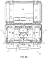
- FIGs. 4A and 4B illustrate an example form factor for portable case 130 that includes a ruggedized and weather-resistant case with a lid. Of course, other form factors may be implemented.
- the internal components are mounted on internal chassis 135, which is in turn suspended within portable case 130 by shock isolators 140.
- Shock isolators 140 are mounted between inside surfaces of portable case 130 and internal chassis 135 to provide mechanical shock absorption to protect the internal components in the event portable case 130 is dropped or otherwise impacted.
- no rigid connections are formed between the internal components mounted on internal chassis 135 and external ports of portable case 130. Rather, all power and communication connections to the internal components are made via flexible cables.
- four instances of shock isolators 140 are each coupled to respective corner regions of internal chassis 135 to suspend internal chassis 135.
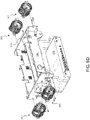
- FIGs. 5A , 5B , and 5D illustrate one possible implementation of internal chassis 135 and shock isolators 140. Of course, other shock isolating mechanisms may be implemented.
- Gateway router 155 is included within portable case 130 and operates to bridge communications between the WAN side adapters and the LAN side adapters, as well as, between the WAN/LAN side adapters and controller 145.
- the WAN side adapters may include cellular modems 170, wired WAN ports 175, or other communication technologies including a WiFi client or otherwise (not illustrated).
- the LAN side adapters may include wireless adapters 160 and wired adapter 165.
- gateway router 155 is additionally capable of bandwidth aggregation and failover support between the various WAN side adapters.
- PAVCP 101 may include multiple cellular modems 170 (e.g., two, four, or more) and gateway router 155 may be configured to aggregate the bandwidth across these multiple independent cellular connections to provide broadband backhaul throughput to remote servers 110 over networks 115.
- gateway router 155 is further capable of aggregating the bandwidth of cellular modems 170 and wired WAN port(s) 175.
- WAN port(s) 175 may provide a local wired internet service provider (ISP) connection.
- Networks 115 represent any number of networks (e.g., the Internet) or intermediary networks (e.g., cellular networks, metro area networks, etc.) that are used on the WAN side to connect with one or more remote servers 110.
- gateway router 155 may be implemented with either the Peplink MAX HD2 or Peplink MAX HD4 routers.
- the illustrated embodiment of PAVCP 101 includes both wireless and wired LAN side adapters for connecting to AVs 105, a weather sensor 125 of a local weather station, and/or various other LAN devices and sensors 120.
- Wireless adapters 160 may include a WiFi access point (e.g., 802.11ac/g/n WLAN) for high speed data transfer and an additional wireless adapter (e.g., 802.15.4 transceiver) that has lower power consumption and lower bandwidth than the WiFi transceiver for connecting to weather sensor 125.
- WiFi access point e.g., 802.11ac/g/n WLAN
- Wired adapter 165 may be included as a wired Ethernet LAN switch, USB hub, and/or otherwise to provide wired connections.
- wired adapter 165 is a powered wired LAN adapter (e.g., power over Ethernet switch) that is capable of powering one or more of LAN devices and sensors 120, since they may be deployed in remote field locations without independent power sources.
- wired adapter 165 is a powered wired LAN adapter (e.g., power over Ethernet switch) that is capable of powering one or more of LAN devices and sensors 120, since they may be deployed in remote field locations without independent power sources.
- all instances of PAVCPs 101 deployed in a particular region e.g., North America
- SSID network name e.g., SSID network name
- Controller 145 is included on internal chassis 135 to choreograph the operation of PAVCP 101 and the other internal components.
- Controller 145 includes local storage 180 and processor 185 coupled to gateway router 155.
- Local storage 180 stores data (e.g., mission log reports from AVs 105, analytics data, mission planning data, etc.) and application instructions executed by processor 185.
- Local storage 180 may be implemented as one or more physical memory units, such as hard disk drives, flash memory, or otherwise.
- Processor 185 may be implemented as one or more general purpose microprocessors.
- External storage may also be coupled to controller 145 via wired adapter 165 (e.g., USB port, etc.).
- the illustrated embodiment of PAVCP 101 includes a power adapter 150 for powering the internal components of PAVCP 101.
- the illustrated embodiment of power adapter 150 includes both an alternating current (AC) power regulator 151 and a direct current (DC) power regulator 152.
- AC alternating current
- DC direct current
- power adapter 150 is capable of powering PAVCP 101 from external sources of either AC or DC power.
- power adapter 150 may be plugged into one of AVs 105 (or other portable batteries) and powered from the internal battery of the AV 105.
- FIG. 2 is a functional block diagram illustrating various functional components of AV ecosystem 100 including software utilities installed on PAVCP 101, in accordance with an embodiment of the disclosure.
- controller 145 includes an AV log utility 205, an AV update utility 210, a remote access utility 215, a metrics collection utility 220, a remote management utility 225, and a sensor utility 230 installed on local storage 180 for execution by processor 185.
- cloud storage 240, remote terminal 245, management/configuration services 250, and mission services 255 are all provided as remote services installed across one or more of remote servers 110.
- the WAN side adapters are not illustrated in FIG. 2 so as not to clutter the drawing.
- AV log utility 205 is executed by controller 145 to manage the downloading, caching, and uploading of mission log reports.
- AV log utility 205 automatically receives the mission log reports from AVs 105 upon returning from a mission and establishing a communication session with PAVCP 101 over a wireless adapter 160 (e.g., WiFi connection) or wired adapter 165.
- the mission log reports include mission data acquired by AVs 105 during their missions.
- the mission log reports may include sensor data (e.g., GPS tracking data), image data, communication logs, telemetry data, or otherwise related to the recently completed flight mission.
- gateway router 155 may aggregate available bandwidth over the WAN side adapters to achieve reliable, broadband backhaul throughput to cloud storage 240.
- AV update utility 210 is a local utility installed on PAVCP 101 that manages the connectivity for transferring mission planning data and/or other updates from cloud storage 240 installed on a remote server 110 to AVs 105.
- Mission planning data may include new mission routes, activities, and other mission execution commands/data for execution or reference by AVs 105 during a new mission.
- the mission planning data is transferred directly to AVs 105 through PAVCP 101.
- the mission planning data is cached locally on local storage 180 and AV update utility 210 establishes a communication session with one or more AVs 105 over a LAN side adapter, and uploads the mission planning data into the connected AVs 105.
- AV update utility 210 may oversee the local distribution of mission planning data from remote server(s) 110 to AVs 105.
- AV update utility 210 further supports local caching of various other types of over-the-air (OTA) updates to be loaded onto AVs 105 at a later time.
- OTA over-the-air
- Remote access utility 215 is a utility that enables an operator at a remote terminal 245 (e.g., remote terminal installed on a remote server 110) to access AVs 105 in real-time.
- Remote access utility 215 facilitates secure encrypted communication sessions (e.g., encrypted VPN tunnels, SSH tunnels, etc.) between remote terminal 245 and AVs 105.
- secure encrypted communication sessions e.g., encrypted VPN tunnels, SSH tunnels, etc.
- These remote management connections between AVs 105 and remote terminal 245 can be used to convey real-time configuration commands and response confirmations for remote operator configurations, servicing, troubleshooting, programming, real-time remote engineering support, etc. of AVs 105.
- Metrics collection utility 220 is executed by controller 145 to monitor and track the operation of AV log utility 205 and AV update utility 210. For example, in one embodiment, metrics collection utility 220 generates analytics data measuring the accumulation rate of mission log reports, the storage occupancy of the mission log reports, and/or the offload rate of the mission log reports from local storage 180. In some cases, AVs 105 may accumulate large sums of data during each mission. As such, monitoring the downloading, caching, and uploading of this data can become an important task in order to provide timely remote oversight and monitoring of AVs 105. Overseeing availability of resources to cache and upload these mission log report is also important, in order to take timely remedial measures if mission log reports accumulate in local storage 180 quicker than they can be uploaded to cloud storage 240. Metrics collection utility 220 is also responsible for reporting this analytics data over the WAN side adapters to management/configuration services 250 installed on a remote server 110.
- Remote management utility 225 is installed on PAVCP 101 to provide remote management, servicing, troubleshooting, remote engineering support, and/or configuration of PAVCP 101 itself. Secure encrypted communications are also supported by remote management utility 225.
- Sensor utilities 230 are executed by controller 145 to acquire, cache, and/or stream real-time or historical sensor data from one or more local sensors to mission services 255.
- sensor utilities 230 stream weather data from a local weather station including weather sensor 125 for publishing by mission services 255.
- LAN devices and sensors 120 include an Automatic Dependent Surveillance - Broadcast (ADS-B) receiver and the manned aircraft broadcasts are streamed to mission services 255.
- LAN devices and sensors 120 include an Automatic Identification System (AIS) receiver for streaming vessel traffic services to mission services 255 in embodiments where AVs 105 are unmanned watercraft.
- AIS Automatic Identification System
- the sensor data streamed to mission services 255 can be amalgamated with sensor data received from many deployed instances of PAVCPs 101 for generating regional databases of real-time data.
- PAVCP 101 may include a GPS receiver and sensor utilities 230 may alos include a location utility that reports location data back to a remote server 110 in real-time. This location data can be combined with the weather data from weather sensor 125 to provide localization of the weather data. Additionally, the location data may be used with geofence operations to issue alarms or reports at a remote server 110 when PAVCP 101 is moved.
- FIG. 3 is a flow chart illustrating a process 300 for operation of the PAVCP 101, in accordance with an embodiment of the disclosure.
- the order in which some or all of the process blocks appear in process 300 should not be deemed limiting. Rather, one of ordinary skill in the art having the benefit of the present disclosure will understand that some of the process blocks may be executed in a variety of orders not illustrated, or even in parallel.
- PAVCP 101 is powered on.
- Power may be obtained from AC or DC external sources.
- DC power regulator 152 is capable of drawing power from 12V or 24V sources.
- AV update utility 210 connects to a remote server 110 to determine whether new mission planning data is available, and if so, downloads the new mission planning data from cloud storage 240 (process block 315), caches the new mission planned data into local storage 180 (process block 320), and subsequently uploads the new mission planning data to AVs 105 (process block 325).
- new mission planning data is transferred directly from cloud storage 240 to AVs 105 merely using PAVCP 101 for connectivity. Accordingly, in these embodiments, the mission planning data is not cached and process block 320 is omitted.
- AV log utility 205 upon returning from a mission the returning AV 105 connects to PAVCP 101, and AV log utility 205 receives a mission log report over a LAN side adapter (process block 335) from the returning AV 105.
- AV log utility 205 caches the mission log report into local storage 180 (process block 340).
- gateway router 155 can aggregate the WAN side bandwidth for broadband backhaul throughput (process block 345) and AV log utility 205 uploads the mission log report to cloud storage 240 on a remote server 110 (process block 350).
- metrics collection utility 220 acquires or otherwise generates analytics data from the local processes and data within PAVCP 101 (process block 360). Subsequently, the analytics data is reported over WAN side adapters to management/configuration services 250 executing on a remote server 110 (process block 365).
- a secure tunnel is established by remote access utility 215 between the AV 105 and remote terminal 245 (process block 375).
- the secure tunnel may use a secure shell (SHH) secure channel to convey real-time configuration commands to AV 105 and deliver response confirmations back to remote terminal 245 (process block 380).
- SHH secure shell
- FIGs. 4A & 4B are perspective view illustrations of a PAVCP 400, in accordance with an embodiment of the disclosure.
- PAVCP 400 is one possible implementation of PAVCP 101.
- FIG. 4A illustrates a front, topside of PAVCP 400 with a lid 405 of its portable case 410 open, while FIG. 4B illustrates a backside of PAVCP 400 with lid 405 closed.
- portable case 410 is a ruggedized, weather-resistant case that protects the internal components of PAVCP 400.
- These internal components include cellular modems and antennae 415 (WAN side adapters), a wireless access point and/or client 420 (LAN side and/or WAN side adapter), a user control panel 425, and flexible cabling 430 for coupling the internal components to external ports 435 on the backside of portable case 410.
- the illustrated embodiment of lid 405 further includes a cable management tray 440 mounted on the inside of lid 405. Cable management tray 440 is sized to stow power/communication cords for PAVCP 400. Cable management tray 440 aligns with a cutout in carriage lid 445, to which many of the internal components mount.
- Carriage lid 445 in turn mounts to a suspended internal chassis (see FIGs. 5A & 5B ) with thumb screws 450.
- Cable management tray 440 prevents the power/communication cords from interfering with the suspension travel of the internal chassis thereby protecting the internal components.
- portable case 410 may be larger and assume a variety of other shapes to accommodate additional/larger internal components.
- portable case 410 may be large enough to house an on-board battery to provide backup power for a limited period of time (e.g., several hours) in the event external power is unavailable.
- portable case 410 may include wheels to ease transport.
- external ports 435 may include external RF connectors for attaching external anntennas or attaching long runs of coaxial cables to provide flexible field setups.
- FIGs. 5A-D illustrate different views of an internal chassis 500 and shock isolators 505 for mounting and protecting the internal components of a PAVCP, in accordance with an embodiment of the disclosure.
- FIG. 5A is a perspective view illustration of internal chassis 500
- FIG. 5B is an exploded perspective view illustration of top side internal components mounted to internal chassis 500
- FIG. 5C is a perspective view illustration of an underside of carriage lid 445 and the topside internal components
- FIG. 5D is an exploded perspective view illustration of bottom side internal components mounted to internal chassis 500, all in accordance with an embodiment of the disclosure.
- Internal chassis 500 is one possible implementation of internal chassis 135 while shock isolators 505 are one possible implementation of shock isolators 140.
- internal chassis 500 provides a support or carriage to which the internal components of PAVCP are mounted along both the upper and lower sides in a sandwiching configuration (see FIGs. 5B and 5D ).
- This sandwiching configuration along with interior rails 515 of internal chassis 500 define a cooling cavity 510 extending through a central portion of the chassis.
- Vent cutouts 520 are disposed at either ends of cool cavity 510 and align with vents 460 on portable case 410 (see FIG. 4B ). Cutouts 530 reduce the overall weight of internal chassis 500.
- internal chassis 500 is fabricated of a bonded lightweight polycarbonate material and is assembled with snap fit, tongue and groove joints 535 so that special adhesive fixtures are not necessary.
- the illustrated embodiment includes shock isolators 505 disposed at the four corner regions of internal chassis 500 and serve to suspend internal chassis 500 along with the internal components within portable case 410 of a PAVCP.
- FIG. 5D illustrates a demonstrative gateway router 570 mounted to an underside of internal chassis 500.
- shock isolators 505 are implemented as wire rope isolators that flex to provide mechanical shock absorption.
- shock isolators 505 are preloaded under compression between the inside surface of portable case 410 and internal chassis 500. Preloading can provide more uniform suspension travel in tension and compression for a given sized isolator.
- other types, configurations, and mounting positions for shock isolators 505 may be implemented.
- Suspension of internal chassis 500 provides greater mechanical shock absorption and suspension travel relative to foam padding for a given interior volume of portable case 410. Furthermore, suspension of interior chassis 500 permits air flow around the internal components for improved convection cooling relative to foam padding.
- fans 540 are disposed at opposing distal ends of cooling cavity 510, with one orientated to push air into cooling cavity 510 and the other oriented to evacuate air from cooling cavity 510.
- a thermostat is provided internal to portable case 410 to provide self-regulated temperature control feedback to fans 540.
- FIG. 5C illustrates the underside of carriage lid 445, which mounts over the topside of internal chassis 500.
- a number of heat sinks 560 are mounted to the underside side of carriage lid 445 and serve to draw heat away from thermally connected internal components.
- heat sinks 560 extend into cooling cavity 510 to provide convection cooling via the air pushed through cooling cavity 510.
- FIGs. 5B and 5C further illustrate how internal components are electrically coupled to external ports 435 via flexible cables 430. No rigid connections that would impede the suspension travel of shock isolators 505 are established between the internal chassis 500, or internal components mounted thereto, and portable case 410.
- a tangible machine-readable storage medium includes any mechanism that provides (i.e., stores) information in a non-transitory form accessible by a machine (e.g., a computer, network device, personal digital assistant, manufacturing tool, any device with a set of one or more processors, etc.).
- a machine-readable storage medium includes recordable/non-recordable media (e.g., read only memory (ROM), random access memory (RAM), magnetic disk storage media, optical storage media, flash memory devices, etc.).
Landscapes
- Engineering & Computer Science (AREA)
- Aviation & Aerospace Engineering (AREA)
- Physics & Mathematics (AREA)
- General Physics & Mathematics (AREA)
- Computer Networks & Wireless Communication (AREA)
- Signal Processing (AREA)
- Astronomy & Astrophysics (AREA)
- Mobile Radio Communication Systems (AREA)
- Selective Calling Equipment (AREA)
Description
- This disclosure relates generally to autonomous vehicles, and in particular but not exclusively, relates to deployment connectivity for autonomous vehicles.
- An unmanned vehicle, which may also be referred to as an autonomous vehicle (AV), is a vehicle capable of travel without a physically-present human operator. An unmanned vehicle may operate in a remote-control mode, in an autonomous mode, or in a partially autonomous mode.
- When an unmanned vehicle operates in a remote-control mode, a pilot or driver that is at a remote location can control the unmanned vehicle via commands that are sent to the unmanned vehicle via a wireless link. When the unmanned vehicle operates in autonomous mode, the unmanned vehicle typically moves based on preprogrammed navigation waypoints, dynamic automation systems, or a combination of these. Further, some unmanned vehicles can operate in both a remote-control mode and an autonomous mode, and in some instances may do so simultaneously. For instance, a remote pilot or driver may wish to leave navigation to an autonomous system while manually performing another task, such as operating a mechanical system for picking up objects, as an example.
- Various types of unmanned vehicles exist for various different environments. For instance, unmanned vehicles exist for operation in the air, on the ground, on or under the water, and in space. Unmanned aerial vehicles (UAVs) are becoming more popular in general. They are being deployed in a variety of different field settings including urban, suburban, and rural environments. The wide variety of deployment environments creates a challenge for providing the connectivity infrastructure that these AVs often rely upon. AV connectivity for long term, or even short term, deployments can require access to backend resources provided by a remote server, cloud services, or command terminal. It is desirable for these backend resources to be available in the full variety of field settings with minimal setup and teardown effort.
-
WO 2016/130716 A2 discloses a method of unmanned aerial vehicle (UAV) operation, including: receiving from a customer a first data request, a first data request having: a first geographic coverage area, and a refresh rate for the first geographic coverage area, planning a first plurality of flight missions to accomplish the first data request, uploading flight missions data representing the first plurality of flight missions into a UAV pod, and deploying the UAV pod. -
US 9,466,219 B1 EP 2 138 921 A2 (HONEYWELL INT INC [US]) 30 December 2009 , discloses a "ground control station" (GCS) that controls a UAV (a drone). The GCS has also a link to a flight control center. The flight control center can get, via the GCS, the position of the UAV. The GCS may be a laptop with two transponders, one to communicate with the UAV, the other to communicate (e.g. via the internet) with the flight control center. - Non-limiting and non-exhaustive embodiments of the invention are described with reference to the following figures, wherein like reference numerals refer to like parts throughout the various views unless otherwise specified. Not all instances of an element are necessarily labeled so as not to clutter the drawings where appropriate. The drawings are not necessarily to scale, emphasis instead being placed upon illustrating the principles being described.
-
FIG. 1 is an illustration of an autonomous vehicle (AV) ecosystem for using a portable AV connectivity platform (PAVCP) that links field deployed AVs to backend remote servers, in accordance with an embodiment of the disclosure. -
FIG. 2 is a functional block diagram illustrating various functional components of the AV ecosystem including software utilities installed on the PAVCP, in accordance with an embodiment of the disclosure. -
FIG. 3 is a flow chart illustrating a process of operation of the PAVCP, in accordance with an embodiment of the disclosure. -
FIG. 4A is a perspective view illustration of the PAVCP with an open lid, in accordance with an embodiment of the disclosure. -
FIG. 4B is a perspective view illustration of a rear of the PAVCP with a closed lid, in accordance with an embodiment of the disclosure. -
FIG. 5A is a perspective view illustration of an internal chassis for mounting internal components within the portable case of the PAVCP, in accordance with an embodiment of the disclosure. -
FIG. 5B is an exploded perspective view illustration of top side components mounted to the internal chassis, in accordance with an embodiment of the disclosure. -
FIG. 5C is a perspective view illustration of an underside of the carriage lid and topside internal components, in accordance with an embodiment of the disclosure. -
FIG. 5D is an exploded perspective view illustration of bottom side internal components mounted to the internal chassis, in accordance with an embodiment of the disclosure. - Embodiments of a system, apparatus, and method of operation for a portable autonomous vehicle connectivity platform (PAVCP) are described herein. In the following description numerous specific details are set forth to provide a thorough understanding of the embodiments. One skilled in the relevant art will recognize, however, that the techniques described herein can be practiced without one or more of the specific details, or with other methods, components, materials, etc. In other instances, well-known structures, materials, or operations are not shown or described in detail to avoid obscuring certain aspects.
- Reference throughout this specification to "one embodiment" or "an embodiment" means that a particular feature, structure, or characteristic described in connection with the embodiment is included in at least one embodiment of the present invention. Thus, the appearances of the phrases "in one embodiment" or "in an embodiment" in various places throughout this specification are not necessarily all referring to the same embodiment. Furthermore, the particular features, structures, or characteristics may be combined in any suitable manner in one or more embodiments.
- The operation of autonomous vehicles (AVs) can require a variety of connectivity infrastructure to achieve full operational support. The connectivity infrastructure may include access to backend resources that can consume significant backhaul throughput. Correspondingly, the local deployed equipment may require local connectivity between the AVs, local sensors (e.g., weather station), local operator terminal or other equipment. Maintaining adequate connectivity infrastructure to AVs across a large spectrum of deployment environments can be challenging.
- Accordingly, embodiments of a portable autonomous vehicle connectivity platform (PAVCP) described herein provide full featured portable connectivity infrastructure for remote deployments in a variety of environments. The PAVCP provides wired and/or wireless local area network (LAN) connectivity for deployed devices along with wired and/or wireless wide area network (WAN) connectivity for backend connections. Although embodiments described herein can provide significant broadband backhaul throughput, local storage (e.g., gigabyte, terabyte, or more) solutions are also provided with the PAVCP to provide rapid data offloading, caching, and time shifted transmission to the backend resources. For example, embodiments of the PAVCP described herein can quickly download mission log reports from the AVs and subsequently upload those large files to cloud data storage services. The PAVCP also provides connectivity for local environment monitoring, along with remote configuration, monitoring, management, and support of the deployed AVs and supporting equipment. In various embodiments, these connectivity services are integrated into a rugged, portable form factor that provides quick setup and teardown with flexible powering and data connectivity options to accommodate a wide variety of deployment environments.
-
FIG. 1 is an illustration of anAV ecosystem 100 in which a PAVCP 101 links field deployed AVs 105 to backend resources includingremote servers 110, in accordance with an embodiment of the disclosure. The illustrated embodiment ofAV ecosystem 100 includes PAVCP 101,AVs 105,servers 110, wide area network (WAN)side networks 115, local area network (LAN) devices andsensors 120, and aweather sensor 125. The illustrated embodiment of PAVCP 101 includes aportable case 130, aninternal chassis 135,shock isolators 140, acontroller 145, apower adapter 150, agateway router 155, wireless adapter(s) 160, awired adapter 165,cellular modems 170, andwired WAN ports 175. The illustrated embodiment ofcontroller 145 includeslocal storage 180 and processor(s) 185. - PAVCP 101 is designed to have a rugged and portable form factor that can be easily and safely transported to various locations to provide connectivity to
AVs 105 even in remote deployment locations. Accordingly,PAVCP 101 includes aportable case 130 that protects the internal components (e.g.,gateway router 155,power adapter 150,controller 145,wireless adapters 160,wired adapter 165,cellular modems 170, wiredWAN ports 175, etc.).FIGs. 4A and4B (discussed in detail below) illustrate an example form factor forportable case 130 that includes a ruggedized and weather-resistant case with a lid. Of course, other form factors may be implemented. - In one embodiment, the internal components are mounted on
internal chassis 135, which is in turn suspended withinportable case 130 byshock isolators 140.Shock isolators 140 are mounted between inside surfaces ofportable case 130 andinternal chassis 135 to provide mechanical shock absorption to protect the internal components in the eventportable case 130 is dropped or otherwise impacted. In one embodiment, no rigid connections are formed between the internal components mounted oninternal chassis 135 and external ports ofportable case 130. Rather, all power and communication connections to the internal components are made via flexible cables. In the illustrated embodiment, four instances ofshock isolators 140 are each coupled to respective corner regions ofinternal chassis 135 to suspendinternal chassis 135.FIGs. 5A ,5B , and5D (discussed in detail below) illustrate one possible implementation ofinternal chassis 135 andshock isolators 140. Of course, other shock isolating mechanisms may be implemented. -
Gateway router 155 is included withinportable case 130 and operates to bridge communications between the WAN side adapters and the LAN side adapters, as well as, between the WAN/LAN side adapters andcontroller 145. The WAN side adapters may includecellular modems 170, wiredWAN ports 175, or other communication technologies including a WiFi client or otherwise (not illustrated). The LAN side adapters may includewireless adapters 160 andwired adapter 165. In one embodiment,gateway router 155 is additionally capable of bandwidth aggregation and failover support between the various WAN side adapters. For example,PAVCP 101 may include multiple cellular modems 170 (e.g., two, four, or more) andgateway router 155 may be configured to aggregate the bandwidth across these multiple independent cellular connections to provide broadband backhaul throughput toremote servers 110 overnetworks 115. In one embodiment,gateway router 155 is further capable of aggregating the bandwidth ofcellular modems 170 and wired WAN port(s) 175. WAN port(s) 175 may provide a local wired internet service provider (ISP) connection.Networks 115 represent any number of networks (e.g., the Internet) or intermediary networks (e.g., cellular networks, metro area networks, etc.) that are used on the WAN side to connect with one or moreremote servers 110. For example,gateway router 155 may be implemented with either the Peplink MAX HD2 or Peplink MAX HD4 routers. - The illustrated embodiment of
PAVCP 101 includes both wireless and wired LAN side adapters for connecting toAVs 105, aweather sensor 125 of a local weather station, and/or various other LAN devices andsensors 120.Wireless adapters 160 may include a WiFi access point (e.g., 802.11ac/g/n WLAN) for high speed data transfer and an additional wireless adapter (e.g., 802.15.4 transceiver) that has lower power consumption and lower bandwidth than the WiFi transceiver for connecting toweather sensor 125. Of course, other wireless transceivers may be implemented.Wired adapter 165 may be included as a wired Ethernet LAN switch, USB hub, and/or otherwise to provide wired connections. In one embodiment,wired adapter 165 is a powered wired LAN adapter (e.g., power over Ethernet switch) that is capable of powering one or more of LAN devices andsensors 120, since they may be deployed in remote field locations without independent power sources. In one embodiment, all instances ofPAVCPs 101 deployed in a particular region (e.g., North America), or even deployed worldwide, are assigned a common SSID network name to one of their LANside wireless adapters 160 to ensureAVs 105 are always able to identify and connect to a deployedPAVCP 101. -
Controller 145 is included oninternal chassis 135 to choreograph the operation ofPAVCP 101 and the other internal components.Controller 145 includeslocal storage 180 andprocessor 185 coupled togateway router 155.Local storage 180 stores data (e.g., mission log reports fromAVs 105, analytics data, mission planning data, etc.) and application instructions executed byprocessor 185.Local storage 180 may be implemented as one or more physical memory units, such as hard disk drives, flash memory, or otherwise.Processor 185 may be implemented as one or more general purpose microprocessors. External storage may also be coupled tocontroller 145 via wired adapter 165 (e.g., USB port, etc.). - The illustrated embodiment of
PAVCP 101 includes apower adapter 150 for powering the internal components ofPAVCP 101. The illustrated embodiment ofpower adapter 150 includes both an alternating current (AC)power regulator 151 and a direct current (DC)power regulator 152. As such,power adapter 150 is capable of poweringPAVCP 101 from external sources of either AC or DC power. In one embodiment,power adapter 150 may be plugged into one of AVs 105 (or other portable batteries) and powered from the internal battery of theAV 105. -
FIG. 2 is a functional block diagram illustrating various functional components ofAV ecosystem 100 including software utilities installed onPAVCP 101, in accordance with an embodiment of the disclosure. For example, the illustrated embodiment ofcontroller 145 includes anAV log utility 205, anAV update utility 210, a remote access utility 215, ametrics collection utility 220, aremote management utility 225, and asensor utility 230 installed onlocal storage 180 for execution byprocessor 185. Correspondingly,cloud storage 240, remote terminal 245, management/configuration services 250, andmission services 255 are all provided as remote services installed across one or more ofremote servers 110. Note, the WAN side adapters are not illustrated inFIG. 2 so as not to clutter the drawing. -
AV log utility 205 is executed bycontroller 145 to manage the downloading, caching, and uploading of mission log reports. During operation,AV log utility 205 automatically receives the mission log reports fromAVs 105 upon returning from a mission and establishing a communication session withPAVCP 101 over a wireless adapter 160 (e.g., WiFi connection) or wiredadapter 165. The mission log reports include mission data acquired byAVs 105 during their missions. In the case of UAVs, the mission log reports may include sensor data (e.g., GPS tracking data), image data, communication logs, telemetry data, or otherwise related to the recently completed flight mission. Once downloaded, the mission log reports are temporarily cached withinlocal storage 180 whileAV log utility 205 uploads each mission log report tocloud storage 240. As mentioned above,gateway router 155 may aggregate available bandwidth over the WAN side adapters to achieve reliable, broadband backhaul throughput tocloud storage 240. -
AV update utility 210 is a local utility installed onPAVCP 101 that manages the connectivity for transferring mission planning data and/or other updates fromcloud storage 240 installed on aremote server 110 toAVs 105. Mission planning data may include new mission routes, activities, and other mission execution commands/data for execution or reference byAVs 105 during a new mission. In one embodiment, the mission planning data is transferred directly toAVs 105 throughPAVCP 101. In other embodiments, the mission planning data is cached locally onlocal storage 180 andAV update utility 210 establishes a communication session with one ormore AVs 105 over a LAN side adapter, and uploads the mission planning data into theconnected AVs 105. Accordingly,AV update utility 210 may oversee the local distribution of mission planning data from remote server(s) 110 toAVs 105. In one embodiment,AV update utility 210 further supports local caching of various other types of over-the-air (OTA) updates to be loaded ontoAVs 105 at a later time. - Remote access utility 215 is a utility that enables an operator at a remote terminal 245 (e.g., remote terminal installed on a remote server 110) to access
AVs 105 in real-time. Remote access utility 215 facilitates secure encrypted communication sessions (e.g., encrypted VPN tunnels, SSH tunnels, etc.) between remote terminal 245 andAVs 105. These remote management connections betweenAVs 105 and remote terminal 245 can be used to convey real-time configuration commands and response confirmations for remote operator configurations, servicing, troubleshooting, programming, real-time remote engineering support, etc. ofAVs 105. -
Metrics collection utility 220 is executed bycontroller 145 to monitor and track the operation ofAV log utility 205 andAV update utility 210. For example, in one embodiment,metrics collection utility 220 generates analytics data measuring the accumulation rate of mission log reports, the storage occupancy of the mission log reports, and/or the offload rate of the mission log reports fromlocal storage 180. In some cases,AVs 105 may accumulate large sums of data during each mission. As such, monitoring the downloading, caching, and uploading of this data can become an important task in order to provide timely remote oversight and monitoring ofAVs 105. Overseeing availability of resources to cache and upload these mission log report is also important, in order to take timely remedial measures if mission log reports accumulate inlocal storage 180 quicker than they can be uploaded tocloud storage 240.Metrics collection utility 220 is also responsible for reporting this analytics data over the WAN side adapters to management/configuration services 250 installed on aremote server 110. -
Remote management utility 225 is installed onPAVCP 101 to provide remote management, servicing, troubleshooting, remote engineering support, and/or configuration ofPAVCP 101 itself. Secure encrypted communications are also supported byremote management utility 225. -
Sensor utilities 230 are executed bycontroller 145 to acquire, cache, and/or stream real-time or historical sensor data from one or more local sensors tomission services 255. For example, in one embodiment,sensor utilities 230 stream weather data from a local weather station includingweather sensor 125 for publishing bymission services 255. In one embodiment, LAN devices andsensors 120 include an Automatic Dependent Surveillance - Broadcast (ADS-B) receiver and the manned aircraft broadcasts are streamed tomission services 255. In yet another embodiment, LAN devices andsensors 120 include an Automatic Identification System (AIS) receiver for streaming vessel traffic services tomission services 255 in embodiments whereAVs 105 are unmanned watercraft. The sensor data streamed tomission services 255 can be amalgamated with sensor data received from many deployed instances ofPAVCPs 101 for generating regional databases of real-time data. In one embodiment,PAVCP 101 may include a GPS receiver andsensor utilities 230 may alos include a location utility that reports location data back to aremote server 110 in real-time. This location data can be combined with the weather data fromweather sensor 125 to provide localization of the weather data. Additionally, the location data may be used with geofence operations to issue alarms or reports at aremote server 110 whenPAVCP 101 is moved. -
FIG. 3 is a flow chart illustrating aprocess 300 for operation of thePAVCP 101, in accordance with an embodiment of the disclosure. The order in which some or all of the process blocks appear inprocess 300 should not be deemed limiting. Rather, one of ordinary skill in the art having the benefit of the present disclosure will understand that some of the process blocks may be executed in a variety of orders not illustrated, or even in parallel. - In a
process block 305,PAVCP 101 is powered on. Power may be obtained from AC or DC external sources. In one embodiment,DC power regulator 152 is capable of drawing power from 12V or 24V sources. - In a
decision block 310,AV update utility 210 connects to aremote server 110 to determine whether new mission planning data is available, and if so, downloads the new mission planning data from cloud storage 240 (process block 315), caches the new mission planned data into local storage 180 (process block 320), and subsequently uploads the new mission planning data to AVs 105 (process block 325). In yet other embodiments, new mission planning data is transferred directly fromcloud storage 240 toAVs 105 merely usingPAVCP 101 for connectivity. Accordingly, in these embodiments, the mission planning data is not cached and process block 320 is omitted. - In a
decision block 330, upon returning from a mission the returningAV 105 connects toPAVCP 101, andAV log utility 205 receives a mission log report over a LAN side adapter (process block 335) from the returningAV 105.AV log utility 205 caches the mission log report into local storage 180 (process block 340). Once downloaded,gateway router 155 can aggregate the WAN side bandwidth for broadband backhaul throughput (process block 345) andAV log utility 205 uploads the mission log report tocloud storage 240 on a remote server 110 (process block 350). - If metrics collection is enabled (decision block 355), then
metrics collection utility 220 acquires or otherwise generates analytics data from the local processes and data within PAVCP 101 (process block 360). Subsequently, the analytics data is reported over WAN side adapters to management/configuration services 250 executing on a remote server 110 (process block 365). - When remote management of an
AV 105 is desired (decision block 370), a secure tunnel is established by remote access utility 215 between theAV 105 and remote terminal 245 (process block 375). For example, the secure tunnel may use a secure shell (SHH) secure channel to convey real-time configuration commands toAV 105 and deliver response confirmations back to remote terminal 245 (process block 380). -
FIGs. 4A &4B are perspective view illustrations of aPAVCP 400, in accordance with an embodiment of the disclosure.PAVCP 400 is one possible implementation ofPAVCP 101.FIG. 4A illustrates a front, topside ofPAVCP 400 with alid 405 of itsportable case 410 open, whileFIG. 4B illustrates a backside ofPAVCP 400 withlid 405 closed. - As illustrated,
portable case 410 is a ruggedized, weather-resistant case that protects the internal components ofPAVCP 400. These internal components include cellular modems and antennae 415 (WAN side adapters), a wireless access point and/or client 420 (LAN side and/or WAN side adapter), auser control panel 425, andflexible cabling 430 for coupling the internal components toexternal ports 435 on the backside ofportable case 410. The illustrated embodiment oflid 405 further includes acable management tray 440 mounted on the inside oflid 405.Cable management tray 440 is sized to stow power/communication cords forPAVCP 400.Cable management tray 440 aligns with a cutout incarriage lid 445, to which many of the internal components mount.Carriage lid 445 in turn mounts to a suspended internal chassis (seeFIGs. 5A &5B ) with thumb screws 450.Cable management tray 440 prevents the power/communication cords from interfering with the suspension travel of the internal chassis thereby protecting the internal components. - It should be appreciated that in some embodiments,
portable case 410 may be larger and assume a variety of other shapes to accommodate additional/larger internal components. For example, in one embodiment,portable case 410 may be large enough to house an on-board battery to provide backup power for a limited period of time (e.g., several hours) in the event external power is unavailable. In larger embodiments,portable case 410 may include wheels to ease transport. In one embodiment,external ports 435 may include external RF connectors for attaching external anntennas or attaching long runs of coaxial cables to provide flexible field setups. -
FIGs. 5A-D illustrate different views of aninternal chassis 500 andshock isolators 505 for mounting and protecting the internal components of a PAVCP, in accordance with an embodiment of the disclosure.FIG. 5A is a perspective view illustration ofinternal chassis 500,FIG. 5B is an exploded perspective view illustration of top side internal components mounted tointernal chassis 500,FIG. 5C is a perspective view illustration of an underside ofcarriage lid 445 and the topside internal components, whileFIG. 5D is an exploded perspective view illustration of bottom side internal components mounted tointernal chassis 500, all in accordance with an embodiment of the disclosure.Internal chassis 500 is one possible implementation ofinternal chassis 135 whileshock isolators 505 are one possible implementation ofshock isolators 140. - Referring to
FIG. 5A ,internal chassis 500 provides a support or carriage to which the internal components of PAVCP are mounted along both the upper and lower sides in a sandwiching configuration (seeFIGs. 5B and5D ). This sandwiching configuration along withinterior rails 515 ofinternal chassis 500 define acooling cavity 510 extending through a central portion of the chassis.Vent cutouts 520 are disposed at either ends ofcool cavity 510 and align withvents 460 on portable case 410 (seeFIG. 4B ).Cutouts 530 reduce the overall weight ofinternal chassis 500. In one embodiment,internal chassis 500 is fabricated of a bonded lightweight polycarbonate material and is assembled with snap fit, tongue andgroove joints 535 so that special adhesive fixtures are not necessary. - Referring to
FIGs. 5B and5D , the illustrated embodiment includesshock isolators 505 disposed at the four corner regions ofinternal chassis 500 and serve to suspendinternal chassis 500 along with the internal components withinportable case 410 of a PAVCP.FIG. 5D illustrates ademonstrative gateway router 570 mounted to an underside ofinternal chassis 500. In the illustrated embodiment,shock isolators 505 are implemented as wire rope isolators that flex to provide mechanical shock absorption. In one embodiment,shock isolators 505 are preloaded under compression between the inside surface ofportable case 410 andinternal chassis 500. Preloading can provide more uniform suspension travel in tension and compression for a given sized isolator. Of course, other types, configurations, and mounting positions forshock isolators 505 may be implemented. - Suspension of
internal chassis 500 provides greater mechanical shock absorption and suspension travel relative to foam padding for a given interior volume ofportable case 410. Furthermore, suspension ofinterior chassis 500 permits air flow around the internal components for improved convection cooling relative to foam padding. In the illustrated embodiment,fans 540 are disposed at opposing distal ends of coolingcavity 510, with one orientated to push air into coolingcavity 510 and the other oriented to evacuate air from coolingcavity 510. Of course, other configurations may be implemented. In one embodiment, a thermostat is provided internal toportable case 410 to provide self-regulated temperature control feedback tofans 540. -
FIG. 5C illustrates the underside ofcarriage lid 445, which mounts over the topside ofinternal chassis 500. As illustrated, a number ofheat sinks 560 are mounted to the underside side ofcarriage lid 445 and serve to draw heat away from thermally connected internal components. Whencarriage lid 445 is mounted ontointernal chassis 500,heat sinks 560 extend into coolingcavity 510 to provide convection cooling via the air pushed through coolingcavity 510. -
FIGs. 5B and5C further illustrate how internal components are electrically coupled toexternal ports 435 viaflexible cables 430. No rigid connections that would impede the suspension travel ofshock isolators 505 are established between theinternal chassis 500, or internal components mounted thereto, andportable case 410. - The processes explained above are described in terms of computer software and hardware. The techniques described may constitute machine-executable instructions embodied within a tangible or non-transitory machine (e.g., computer) readable storage medium, that when executed by a machine will cause the machine to perform the operations described. Additionally, the processes may be embodied within hardware, such as an application specific integrated circuit ("ASIC") or otherwise.
- A tangible machine-readable storage medium includes any mechanism that provides (i.e., stores) information in a non-transitory form accessible by a machine (e.g., a computer, network device, personal digital assistant, manufacturing tool, any device with a set of one or more processors, etc.). For example, a machine-readable storage medium includes recordable/non-recordable media (e.g., read only memory (ROM), random access memory (RAM), magnetic disk storage media, optical storage media, flash memory devices, etc.).
- The above description of illustrated embodiments of the invention, including what is described in the Abstract, is not intended to be exhaustive or to limit the invention to the precise forms disclosed. Specific embodiments of, and examples for, the invention are described herein for illustrative purposes.
Claims (13)
- A portable autonomous vehicle connectivity platform (101; 400), comprising:a portable case (130; 410), wherein the portable case comprises a ruggedized, weather-resistant case with a lid;one or more local area network [LAN] side adapters (160, 165) disposed within the portable case (130; 410) configured to communicate with one or more local devices including an autonomous vehicle [AV] (105);one or more wide area network [WAN] side adapters (170, 175) disposed within the portable case (130; 410) configured to communicate with one or more remote servers (110);a gateway router (155) disposed within the portable case (130; 410) for bridging communications between the one or more LAN side adapters (160, 165) and the one or more WAN side adapters (170, 175); anda controller (145) including a processor (185) and local storage (180) coupled to the gateway router (155), wherein the local storage (180) stores instructions that, when executed by the processor (185), causes the portable autonomous vehicle connectivity platform (101; 400) to perform operations including:establishing a remote management connection between a remote terminal (245) and the AV (105) via the portable autonomous vehicle connectivity platform (101; 400);conveying real-time configuration commands and response confirmations between the AV (105) and the remote terminal (245) over an encrypted communication session between the AV (105) and the remote terminal (245).receiving a mission log report from the AV (105) over the one or more LAN side adapters (160, 165) after the AV (105) returns from a mission;caching the mission log report in the local storage (180); andtransmitting the mission log report from the local storage (180) to the one or more remote servers (110) over the one or more WAN side adapters (170, 175).
- The portable autonomous vehicle connectivity platform of claim 1, wherein the one or more WAN side adapters includes a plurality of cellular modems (170) and the one or more LAN side adapters includes a wireless LAN adapter (160) and a powered wired LAN adapter (165).
- The portable autonomous vehicle connectivity platform of claim 2, wherein the AV comprises one of a plurality of unmanned aerial vehicles [UAVs], and wherein the local storage stores further instructions that, when executed by the processor, causes the portable autonomous vehicle connectivity platform to perform further operations including:receiving a plurality of mission log reports from the UAVs over the wireless LAN adapter;caching the mission log reports in the local storage upon return of the UAVs after flying missions;aggregating a bandwidth of the plurality of cellular modems; andtransmitting the mission log reports to the one or more remote servers over the cellular modems.
- The portable autonomous vehicle connectivity platform of claim 3, wherein the local storage stores further instructions that, when executed by the processor, causes the portable autonomous vehicle connectivity platform to perform further operations including:generating analytics data measuring one or more of an accumulation rate of the mission log reports, a storage occupancy of the mission log reports, or an offload rate of the mission log reports; andreporting the analytics data over the WAN side adapters to one of the remote servers.
- The portable autonomous vehicle connectivity platform of any of claims 2-4, wherein the one or more LAN side adapters further includes an additional wireless adapter having a lower power consumption and lower bandwidth than the wireless LAN adapter, for wireless coupling to a local weather station.
- The portable autonomous vehicle connectivity platform of any preceding claim, wherein the local storage stores further instructions that, when executed by the processor, causes the portable autonomous vehicle connectivity platform to perform further operations including:receiving mission planning data describing a new mission route for the AV over the one or more WAN side adapters from one of the remote servers; andtransferring the mission planning data to the AV upon establishing a communication session with the AV via the one or more LAN side adapters.
- The portable autonomous vehicle connectivity platform of any preceding claim, further comprising:
a power adapter (150) disposed within the portable case and coupled to power the one or more LAN side adapters, the one or more WAN side adapters, the gateway router, and the controller, wherein the power adapter (150) includes alternating current [AC] and direct current [DC] power regulators (152) for powering internal components of the portable autonomous vehicle connectivity platform from external sources of either AC power or DC power. - The portable autonomous vehicle connectivity platform of any preceding claim, wherein the local storage stores further instructions that, when executed by the processor, causes the portable autonomous vehicle connectivity platform to perform further operations including:receiving an over-the-air [OTA] software update for the AV over one or more of the WAN side adapters;caching the OTA software update in the local storage; andtransmitting the OTA software update from the local storage to the AV over the LAN side adapter.
- The portable autonomous vehicle connectivity platform of any preceding claim, further comprising:an internal chassis (135; 500) disposed within the portable case and to which internal components including the one or more LAN side adapters, the one or more WAN side adapters, the gateway router, and the controller are mounted; andshock isolators (140; 505) mounted to inside surfaces of the portable case and mechanically coupled to the internal chassis (135; 500) to suspend the internal chassis (135; 500) within the portable case.
- The portable autonomous vehicle connectivity platform of claim 9, wherein the shock isolators comprise four instances of the shock isolators each coupling a respective corner region of the internal chassis to one of the inside surfaces of the portable case.
- The portable autonomous vehicle connectivity platform of claim 9 or claim 10, wherein the shock isolators are preloaded under compression between the inside surfaces and the internal chassis.
- The portable autonomous vehicle connectivity platform of any of claims 9 to 11, wherein the portable autonomous vehicle connectivity platform includes no rigid connections between the internal components and the portable case and wherein all power or communication connections between external ports on the portable case and the internal components are connected via flexible cables (430).
- The portable autonomous vehicle connectivity platform of any of claims 9 to 12, wherein the internal chassis includes a cooling cavity (510) extending through a central portion of the internal chassis and aligned with vents (460) disposed in the portable case, and wherein the internal components are mounted to top and bottom sides of the internal chassis sandwiching both sides of the cooling cavity (510) with one or more heat sinks (560) extending into the cooling cavity (510).
Applications Claiming Priority (2)
| Application Number | Priority Date | Filing Date | Title |
|---|---|---|---|
| US15/918,554 US10645603B2 (en) | 2018-03-12 | 2018-03-12 | Portable autonomous vehicle connectivity platform |
| PCT/US2019/021198 WO2019177868A1 (en) | 2018-03-12 | 2019-03-07 | Portable autonomous vehicle connectivity platform |
Publications (2)
| Publication Number | Publication Date |
|---|---|
| EP3766302A1 EP3766302A1 (en) | 2021-01-20 |
| EP3766302B1 true EP3766302B1 (en) | 2022-09-28 |
Family
ID=65911256
Family Applications (1)
| Application Number | Title | Priority Date | Filing Date |
|---|---|---|---|
| EP19713611.2A Active EP3766302B1 (en) | 2018-03-12 | 2019-03-07 | Portable autonomous vehicle connectivity platform |
Country Status (6)
| Country | Link |
|---|---|
| US (1) | US10645603B2 (en) |
| EP (1) | EP3766302B1 (en) |
| CN (1) | CN111837450B (en) |
| AU (1) | AU2019234381B2 (en) |
| SG (1) | SG11202008691YA (en) |
| WO (1) | WO2019177868A1 (en) |
Families Citing this family (12)
| Publication number | Priority date | Publication date | Assignee | Title |
|---|---|---|---|---|
| US10703383B1 (en) * | 2019-04-05 | 2020-07-07 | State Farm Mutual Automobile Insurance Company | Systems and methods for detecting software interactions for individual autonomous vehicles |
| US11321972B1 (en) | 2019-04-05 | 2022-05-03 | State Farm Mutual Automobile Insurance Company | Systems and methods for detecting software interactions for autonomous vehicles within changing environmental conditions |
| US11048261B1 (en) | 2019-04-05 | 2021-06-29 | State Farm Mutual Automobile Insurance Company | Systems and methods for evaluating autonomous vehicle software interactions for proposed trips |
| US10913464B1 (en) * | 2019-10-11 | 2021-02-09 | GM Global Technology Operations LLC | Intelligent escalation strategy for autonomous vehicle |
| JP2022550214A (en) * | 2019-11-21 | 2022-11-30 | スマートスカイ ネットワークス エルエルシー | Method and apparatus for enhancing air-to-ground WiFi systems |
| US12015523B2 (en) * | 2020-03-11 | 2024-06-18 | Nec Corporation | Communication apparatus, data recording method, and non-transitory computer-readable medium |
| US11600186B2 (en) | 2020-08-04 | 2023-03-07 | Wing Aviation Llc | Verification of unmanned aerial vehicle ADS-B receiver operability |
| WO2023009804A1 (en) * | 2021-07-29 | 2023-02-02 | Tmgcore, Inc. | Mobile command and control centers and boxes therefore |
| US12039483B2 (en) | 2022-05-20 | 2024-07-16 | Wing Aviation Llc | Staging unmanned aerial vehicles at merchant facilities |
| US20240422582A1 (en) * | 2023-06-16 | 2024-12-19 | James L. Gilbert | Enhancements for robust multi-station communication in remote environments |
| WO2025101234A2 (en) | 2023-06-23 | 2025-05-15 | File David J | Twin fan, redundantly configured vertical lift vehicle |
| WO2024260482A1 (en) * | 2023-06-23 | 2024-12-26 | České vysoké učení technické v Praze | Integrated mobile device for interconnecting privileged and unprivileged devices in field deployments |
Family Cites Families (13)
| Publication number | Priority date | Publication date | Assignee | Title |
|---|---|---|---|---|
| US20040085944A1 (en) | 2002-11-04 | 2004-05-06 | Boehm Lawrence D. | Portable wireless internet gateway |
| US9569587B2 (en) | 2006-12-29 | 2017-02-14 | Kip Prod Pi Lp | Multi-services application gateway and system employing the same |
| US8358677B2 (en) | 2008-06-24 | 2013-01-22 | Honeywell International Inc. | Virtual or remote transponder |
| US8096254B1 (en) * | 2010-03-29 | 2012-01-17 | The United States Of American As Represented By The Secretary Of The Navy | Unmanned vehicle launch and recovery system |
| US9981740B2 (en) | 2010-08-06 | 2018-05-29 | Northrup Grumman Systems Corporation | Layered architecture for customer payload systems |
| US9466219B1 (en) | 2014-06-27 | 2016-10-11 | Rockwell Collins, Inc. | Unmanned vehicle mission planning, coordination and collaboration |
| CN203480249U (en) | 2013-09-24 | 2014-03-12 | 安徽泽众安全科技有限公司 | Unmanned aerial vehicle ground monitoring control system |
| EP3053361A4 (en) | 2013-10-01 | 2017-04-26 | Argent Line, LLC | Communications platform |
| US20160045381A1 (en) * | 2014-08-13 | 2016-02-18 | Tribalco, Llc | Method and system for medical kits for tactical deployment |
| US9880563B2 (en) * | 2015-02-11 | 2018-01-30 | Aerovironment, Inc. | Geographic survey system for vertical take-off and landing (VTOL) unmanned aerial vehicles (UAVs) |
| US10142172B2 (en) | 2015-07-22 | 2018-11-27 | Facebook, Inc. | Internet service provider management platform |
| SG11201806440WA (en) * | 2016-01-29 | 2018-08-30 | Garuda Robotics Pte Ltd | System and method for controlling an unmanned vehicle and releasing a payload from the same |
| CN106628217B (en) * | 2016-12-23 | 2019-02-26 | 深圳市道通智能航空技术有限公司 | A detachable pan-tilt connection device and unmanned aerial vehicle |
-
2018
- 2018-03-12 US US15/918,554 patent/US10645603B2/en active Active
-
2019
- 2019-03-07 AU AU2019234381A patent/AU2019234381B2/en active Active
- 2019-03-07 WO PCT/US2019/021198 patent/WO2019177868A1/en not_active Ceased
- 2019-03-07 SG SG11202008691YA patent/SG11202008691YA/en unknown
- 2019-03-07 CN CN201980018655.2A patent/CN111837450B/en active Active
- 2019-03-07 EP EP19713611.2A patent/EP3766302B1/en active Active
Also Published As
| Publication number | Publication date |
|---|---|
| SG11202008691YA (en) | 2020-10-29 |
| CN111837450B (en) | 2023-08-01 |
| US10645603B2 (en) | 2020-05-05 |
| US20190281483A1 (en) | 2019-09-12 |
| CN111837450A (en) | 2020-10-27 |
| AU2019234381A1 (en) | 2020-09-17 |
| WO2019177868A1 (en) | 2019-09-19 |
| EP3766302A1 (en) | 2021-01-20 |
| AU2019234381B2 (en) | 2021-05-20 |
Similar Documents
| Publication | Publication Date | Title |
|---|---|---|
| AU2019234381B2 (en) | Portable autonomous vehicle connectivity platform | |
| US11271637B2 (en) | Network capacity management | |
| US11394457B2 (en) | Method, apparatus and system of providing communication coverage to an unmanned aerial vehicle | |
| US9927807B1 (en) | Command and control of unmanned vehicles using cellular and IP mesh technologies for data convergence | |
| US7908042B2 (en) | Methods and apparatus for wireless upload and download of aircraft data | |
| EP3046273B1 (en) | System and method for connecting aircraft to networks on ground | |
| TWI763651B (en) | Managing network communication of an unmanned autonomous vehicle | |
| US11962390B2 (en) | Methods, apparatus and system for extended wireless communications | |
| CN111262614A (en) | Unmanned aerial vehicle modular redundant communication | |
| EP1368725B1 (en) | Methods and apparatus for wireless upload and download of aircraft data | |
| US20180020081A1 (en) | Managing a Parameter of an Unmanned Autonomous Vehicle Based on Manned Aviation Data | |
| WO2021168485A1 (en) | Distribution of location information to aid user equipment link with moving non-terrestrial network nodes | |
| US20250030477A1 (en) | Method of providing edge computing service and network therefor | |
| Sander et al. | Ground Segment Design for Command & Control and Payload Data of High Altitude Platforms | |
| Jadon et al. | A database system architecture for air-to-ground uas link characterization | |
| Olatunbosun | An Efficient Model for Communication Systems in Unmanned Aerial Vehicles (UAVs) | |
| Fourati et al. | for Unmanned Aerial Vehicle System |
Legal Events
| Date | Code | Title | Description |
|---|---|---|---|
| STAA | Information on the status of an ep patent application or granted ep patent |
Free format text: STATUS: UNKNOWN |
|
| STAA | Information on the status of an ep patent application or granted ep patent |
Free format text: STATUS: THE INTERNATIONAL PUBLICATION HAS BEEN MADE |
|
| PUAI | Public reference made under article 153(3) epc to a published international application that has entered the european phase |
Free format text: ORIGINAL CODE: 0009012 |
|
| STAA | Information on the status of an ep patent application or granted ep patent |
Free format text: STATUS: REQUEST FOR EXAMINATION WAS MADE |
|
| 17P | Request for examination filed |
Effective date: 20200824 |
|
| AK | Designated contracting states |
Kind code of ref document: A1 Designated state(s): AL AT BE BG CH CY CZ DE DK EE ES FI FR GB GR HR HU IE IS IT LI LT LU LV MC MK MT NL NO PL PT RO RS SE SI SK SM TR |
|
| AX | Request for extension of the european patent |
Extension state: BA ME |
|
| DAV | Request for validation of the european patent (deleted) | ||
| DAX | Request for extension of the european patent (deleted) | ||
| GRAP | Despatch of communication of intention to grant a patent |
Free format text: ORIGINAL CODE: EPIDOSNIGR1 |
|
| STAA | Information on the status of an ep patent application or granted ep patent |
Free format text: STATUS: GRANT OF PATENT IS INTENDED |
|
| INTG | Intention to grant announced |
Effective date: 20220429 |
|
| GRAS | Grant fee paid |
Free format text: ORIGINAL CODE: EPIDOSNIGR3 |
|
| GRAA | (expected) grant |
Free format text: ORIGINAL CODE: 0009210 |
|
| STAA | Information on the status of an ep patent application or granted ep patent |
Free format text: STATUS: THE PATENT HAS BEEN GRANTED |
|
| AK | Designated contracting states |
Kind code of ref document: B1 Designated state(s): AL AT BE BG CH CY CZ DE DK EE ES FI FR GB GR HR HU IE IS IT LI LT LU LV MC MK MT NL NO PL PT RO RS SE SI SK SM TR |
|
| REG | Reference to a national code |
Ref country code: GB Ref legal event code: FG4D |
|
| REG | Reference to a national code |
Ref country code: CH Ref legal event code: EP |
|
| REG | Reference to a national code |
Ref country code: AT Ref legal event code: REF Ref document number: 1522147 Country of ref document: AT Kind code of ref document: T Effective date: 20221015 |
|
| REG | Reference to a national code |
Ref country code: FI Ref legal event code: FGE |
|
| REG | Reference to a national code |
Ref country code: DE Ref legal event code: R096 Ref document number: 602019020035 Country of ref document: DE |
|
| REG | Reference to a national code |
Ref country code: IE Ref legal event code: FG4D |
|
| REG | Reference to a national code |
Ref country code: LT Ref legal event code: MG9D |
|
| PG25 | Lapsed in a contracting state [announced via postgrant information from national office to epo] |
Ref country code: SE Free format text: LAPSE BECAUSE OF FAILURE TO SUBMIT A TRANSLATION OF THE DESCRIPTION OR TO PAY THE FEE WITHIN THE PRESCRIBED TIME-LIMIT Effective date: 20220928 Ref country code: RS Free format text: LAPSE BECAUSE OF FAILURE TO SUBMIT A TRANSLATION OF THE DESCRIPTION OR TO PAY THE FEE WITHIN THE PRESCRIBED TIME-LIMIT Effective date: 20220928 Ref country code: NO Free format text: LAPSE BECAUSE OF FAILURE TO SUBMIT A TRANSLATION OF THE DESCRIPTION OR TO PAY THE FEE WITHIN THE PRESCRIBED TIME-LIMIT Effective date: 20221228 Ref country code: LV Free format text: LAPSE BECAUSE OF FAILURE TO SUBMIT A TRANSLATION OF THE DESCRIPTION OR TO PAY THE FEE WITHIN THE PRESCRIBED TIME-LIMIT Effective date: 20220928 Ref country code: LT Free format text: LAPSE BECAUSE OF FAILURE TO SUBMIT A TRANSLATION OF THE DESCRIPTION OR TO PAY THE FEE WITHIN THE PRESCRIBED TIME-LIMIT Effective date: 20220928 |
|
| REG | Reference to a national code |
Ref country code: NL Ref legal event code: MP Effective date: 20220928 |
|
| REG | Reference to a national code |
Ref country code: AT Ref legal event code: MK05 Ref document number: 1522147 Country of ref document: AT Kind code of ref document: T Effective date: 20220928 |
|
| PG25 | Lapsed in a contracting state [announced via postgrant information from national office to epo] |
Ref country code: HR Free format text: LAPSE BECAUSE OF FAILURE TO SUBMIT A TRANSLATION OF THE DESCRIPTION OR TO PAY THE FEE WITHIN THE PRESCRIBED TIME-LIMIT Effective date: 20220928 Ref country code: GR Free format text: LAPSE BECAUSE OF FAILURE TO SUBMIT A TRANSLATION OF THE DESCRIPTION OR TO PAY THE FEE WITHIN THE PRESCRIBED TIME-LIMIT Effective date: 20221229 |
|
| PG25 | Lapsed in a contracting state [announced via postgrant information from national office to epo] |
Ref country code: SM Free format text: LAPSE BECAUSE OF FAILURE TO SUBMIT A TRANSLATION OF THE DESCRIPTION OR TO PAY THE FEE WITHIN THE PRESCRIBED TIME-LIMIT Effective date: 20220928 Ref country code: RO Free format text: LAPSE BECAUSE OF FAILURE TO SUBMIT A TRANSLATION OF THE DESCRIPTION OR TO PAY THE FEE WITHIN THE PRESCRIBED TIME-LIMIT Effective date: 20220928 Ref country code: PT Free format text: LAPSE BECAUSE OF FAILURE TO SUBMIT A TRANSLATION OF THE DESCRIPTION OR TO PAY THE FEE WITHIN THE PRESCRIBED TIME-LIMIT Effective date: 20230130 Ref country code: ES Free format text: LAPSE BECAUSE OF FAILURE TO SUBMIT A TRANSLATION OF THE DESCRIPTION OR TO PAY THE FEE WITHIN THE PRESCRIBED TIME-LIMIT Effective date: 20220928 Ref country code: CZ Free format text: LAPSE BECAUSE OF FAILURE TO SUBMIT A TRANSLATION OF THE DESCRIPTION OR TO PAY THE FEE WITHIN THE PRESCRIBED TIME-LIMIT Effective date: 20220928 Ref country code: AT Free format text: LAPSE BECAUSE OF FAILURE TO SUBMIT A TRANSLATION OF THE DESCRIPTION OR TO PAY THE FEE WITHIN THE PRESCRIBED TIME-LIMIT Effective date: 20220928 |
|
| PG25 | Lapsed in a contracting state [announced via postgrant information from national office to epo] |
Ref country code: SK Free format text: LAPSE BECAUSE OF FAILURE TO SUBMIT A TRANSLATION OF THE DESCRIPTION OR TO PAY THE FEE WITHIN THE PRESCRIBED TIME-LIMIT Effective date: 20220928 Ref country code: PL Free format text: LAPSE BECAUSE OF FAILURE TO SUBMIT A TRANSLATION OF THE DESCRIPTION OR TO PAY THE FEE WITHIN THE PRESCRIBED TIME-LIMIT Effective date: 20220928 Ref country code: IS Free format text: LAPSE BECAUSE OF FAILURE TO SUBMIT A TRANSLATION OF THE DESCRIPTION OR TO PAY THE FEE WITHIN THE PRESCRIBED TIME-LIMIT Effective date: 20230128 Ref country code: EE Free format text: LAPSE BECAUSE OF FAILURE TO SUBMIT A TRANSLATION OF THE DESCRIPTION OR TO PAY THE FEE WITHIN THE PRESCRIBED TIME-LIMIT Effective date: 20220928 |
|
| REG | Reference to a national code |
Ref country code: DE Ref legal event code: R097 Ref document number: 602019020035 Country of ref document: DE |
|
| PG25 | Lapsed in a contracting state [announced via postgrant information from national office to epo] |
Ref country code: NL Free format text: LAPSE BECAUSE OF FAILURE TO SUBMIT A TRANSLATION OF THE DESCRIPTION OR TO PAY THE FEE WITHIN THE PRESCRIBED TIME-LIMIT Effective date: 20220928 Ref country code: AL Free format text: LAPSE BECAUSE OF FAILURE TO SUBMIT A TRANSLATION OF THE DESCRIPTION OR TO PAY THE FEE WITHIN THE PRESCRIBED TIME-LIMIT Effective date: 20220928 |
|
| P01 | Opt-out of the competence of the unified patent court (upc) registered |
Effective date: 20230530 |
|
| PG25 | Lapsed in a contracting state [announced via postgrant information from national office to epo] |
Ref country code: DK Free format text: LAPSE BECAUSE OF FAILURE TO SUBMIT A TRANSLATION OF THE DESCRIPTION OR TO PAY THE FEE WITHIN THE PRESCRIBED TIME-LIMIT Effective date: 20220928 |
|
| PLBE | No opposition filed within time limit |
Free format text: ORIGINAL CODE: 0009261 |
|
| STAA | Information on the status of an ep patent application or granted ep patent |
Free format text: STATUS: NO OPPOSITION FILED WITHIN TIME LIMIT |
|
| 26N | No opposition filed |
Effective date: 20230629 |
|
| PG25 | Lapsed in a contracting state [announced via postgrant information from national office to epo] |
Ref country code: MC Free format text: LAPSE BECAUSE OF FAILURE TO SUBMIT A TRANSLATION OF THE DESCRIPTION OR TO PAY THE FEE WITHIN THE PRESCRIBED TIME-LIMIT Effective date: 20220928 |
|
| PG25 | Lapsed in a contracting state [announced via postgrant information from national office to epo] |
Ref country code: SI Free format text: LAPSE BECAUSE OF FAILURE TO SUBMIT A TRANSLATION OF THE DESCRIPTION OR TO PAY THE FEE WITHIN THE PRESCRIBED TIME-LIMIT Effective date: 20220928 |
|
| REG | Reference to a national code |
Ref country code: BE Ref legal event code: MM Effective date: 20230331 |
|
| PG25 | Lapsed in a contracting state [announced via postgrant information from national office to epo] |
Ref country code: LU Free format text: LAPSE BECAUSE OF NON-PAYMENT OF DUE FEES Effective date: 20230307 |
|
| REG | Reference to a national code |
Ref country code: IE Ref legal event code: MM4A |
|
| PG25 | Lapsed in a contracting state [announced via postgrant information from national office to epo] |
Ref country code: IE Free format text: LAPSE BECAUSE OF NON-PAYMENT OF DUE FEES Effective date: 20230307 |
|
| PG25 | Lapsed in a contracting state [announced via postgrant information from national office to epo] |
Ref country code: BE Free format text: LAPSE BECAUSE OF NON-PAYMENT OF DUE FEES Effective date: 20230331 |
|
| PG25 | Lapsed in a contracting state [announced via postgrant information from national office to epo] |
Ref country code: IT Free format text: LAPSE BECAUSE OF FAILURE TO SUBMIT A TRANSLATION OF THE DESCRIPTION OR TO PAY THE FEE WITHIN THE PRESCRIBED TIME-LIMIT Effective date: 20220928 |
|
| PG25 | Lapsed in a contracting state [announced via postgrant information from national office to epo] |
Ref country code: BG Free format text: LAPSE BECAUSE OF FAILURE TO SUBMIT A TRANSLATION OF THE DESCRIPTION OR TO PAY THE FEE WITHIN THE PRESCRIBED TIME-LIMIT Effective date: 20220928 |
|
| PG25 | Lapsed in a contracting state [announced via postgrant information from national office to epo] |
Ref country code: BG Free format text: LAPSE BECAUSE OF FAILURE TO SUBMIT A TRANSLATION OF THE DESCRIPTION OR TO PAY THE FEE WITHIN THE PRESCRIBED TIME-LIMIT Effective date: 20220928 |
|
| PG25 | Lapsed in a contracting state [announced via postgrant information from national office to epo] |
Ref country code: CY Free format text: LAPSE BECAUSE OF FAILURE TO SUBMIT A TRANSLATION OF THE DESCRIPTION OR TO PAY THE FEE WITHIN THE PRESCRIBED TIME-LIMIT; INVALID AB INITIO Effective date: 20190307 |
|
| PG25 | Lapsed in a contracting state [announced via postgrant information from national office to epo] |
Ref country code: HU Free format text: LAPSE BECAUSE OF FAILURE TO SUBMIT A TRANSLATION OF THE DESCRIPTION OR TO PAY THE FEE WITHIN THE PRESCRIBED TIME-LIMIT; INVALID AB INITIO Effective date: 20190307 |
|
| REG | Reference to a national code |
Ref country code: CH Ref legal event code: R17 Free format text: ST27 STATUS EVENT CODE: U-0-0-R10-R17 (AS PROVIDED BY THE NATIONAL OFFICE) Effective date: 20251031 |
|
| PG25 | Lapsed in a contracting state [announced via postgrant information from national office to epo] |
Ref country code: TR Free format text: LAPSE BECAUSE OF FAILURE TO SUBMIT A TRANSLATION OF THE DESCRIPTION OR TO PAY THE FEE WITHIN THE PRESCRIBED TIME-LIMIT Effective date: 20220928 |
|
| REG | Reference to a national code |
Ref country code: CH Ref legal event code: U11 Free format text: ST27 STATUS EVENT CODE: U-0-0-U10-U11 (AS PROVIDED BY THE NATIONAL OFFICE) Effective date: 20260401 |
|
| PGFP | Annual fee paid to national office [announced via postgrant information from national office to epo] |
Ref country code: GB Payment date: 20260323 Year of fee payment: 8 |
|
| PGFP | Annual fee paid to national office [announced via postgrant information from national office to epo] |
Ref country code: DE Payment date: 20260320 Year of fee payment: 8 |
|
| PGFP | Annual fee paid to national office [announced via postgrant information from national office to epo] |
Ref country code: FI Payment date: 20260323 Year of fee payment: 8 |
|
| PGFP | Annual fee paid to national office [announced via postgrant information from national office to epo] |
Ref country code: FR Payment date: 20260323 Year of fee payment: 8 |
|
| PGFP | Annual fee paid to national office [announced via postgrant information from national office to epo] |
Ref country code: CH Payment date: 20260401 Year of fee payment: 8 |