EP3765787B1 - Motorisierter einbaustrahler mit rack für drehung um eine longitudinale achse - Google Patents
Motorisierter einbaustrahler mit rack für drehung um eine longitudinale achse Download PDFInfo
- Publication number
- EP3765787B1 EP3765787B1 EP19716566.5A EP19716566A EP3765787B1 EP 3765787 B1 EP3765787 B1 EP 3765787B1 EP 19716566 A EP19716566 A EP 19716566A EP 3765787 B1 EP3765787 B1 EP 3765787B1
- Authority
- EP
- European Patent Office
- Prior art keywords
- spotlight
- motor
- rack
- wall
- shaft
- Prior art date
- Legal status (The legal status is an assumption and is not a legal conclusion. Google has not performed a legal analysis and makes no representation as to the accuracy of the status listed.)
- Active
Links
Images



Classifications
-
- F—MECHANICAL ENGINEERING; LIGHTING; HEATING; WEAPONS; BLASTING
- F21—LIGHTING
- F21V—FUNCTIONAL FEATURES OR DETAILS OF LIGHTING DEVICES OR SYSTEMS THEREOF; STRUCTURAL COMBINATIONS OF LIGHTING DEVICES WITH OTHER ARTICLES, NOT OTHERWISE PROVIDED FOR
- F21V21/00—Supporting, suspending, or attaching arrangements for lighting devices; Hand grips
- F21V21/14—Adjustable mountings
- F21V21/15—Adjustable mountings specially adapted for power operation, e.g. by remote control
-
- F—MECHANICAL ENGINEERING; LIGHTING; HEATING; WEAPONS; BLASTING
- F21—LIGHTING
- F21S—NON-PORTABLE LIGHTING DEVICES; SYSTEMS THEREOF; VEHICLE LIGHTING DEVICES SPECIALLY ADAPTED FOR VEHICLE EXTERIORS
- F21S8/00—Lighting devices intended for fixed installation
- F21S8/02—Lighting devices intended for fixed installation of recess-mounted type, e.g. downlighters
- F21S8/026—Lighting devices intended for fixed installation of recess-mounted type, e.g. downlighters intended to be recessed in a ceiling or like overhead structure, e.g. suspended ceiling
-
- F—MECHANICAL ENGINEERING; LIGHTING; HEATING; WEAPONS; BLASTING
- F21—LIGHTING
- F21V—FUNCTIONAL FEATURES OR DETAILS OF LIGHTING DEVICES OR SYSTEMS THEREOF; STRUCTURAL COMBINATIONS OF LIGHTING DEVICES WITH OTHER ARTICLES, NOT OTHERWISE PROVIDED FOR
- F21V21/00—Supporting, suspending, or attaching arrangements for lighting devices; Hand grips
- F21V21/02—Wall, ceiling, or floor bases; Fixing pendants or arms to the bases
- F21V21/04—Recessed bases
-
- F—MECHANICAL ENGINEERING; LIGHTING; HEATING; WEAPONS; BLASTING
- F21—LIGHTING
- F21V—FUNCTIONAL FEATURES OR DETAILS OF LIGHTING DEVICES OR SYSTEMS THEREOF; STRUCTURAL COMBINATIONS OF LIGHTING DEVICES WITH OTHER ARTICLES, NOT OTHERWISE PROVIDED FOR
- F21V14/00—Controlling the distribution of the light emitted by adjustment of elements
- F21V14/02—Controlling the distribution of the light emitted by adjustment of elements by movement of light sources
-
- F—MECHANICAL ENGINEERING; LIGHTING; HEATING; WEAPONS; BLASTING
- F21—LIGHTING
- F21V—FUNCTIONAL FEATURES OR DETAILS OF LIGHTING DEVICES OR SYSTEMS THEREOF; STRUCTURAL COMBINATIONS OF LIGHTING DEVICES WITH OTHER ARTICLES, NOT OTHERWISE PROVIDED FOR
- F21V23/00—Arrangement of electric circuit elements in or on lighting devices
- F21V23/04—Arrangement of electric circuit elements in or on lighting devices the elements being switches
- F21V23/0435—Arrangement of electric circuit elements in or on lighting devices the elements being switches activated by remote control means
-
- F—MECHANICAL ENGINEERING; LIGHTING; HEATING; WEAPONS; BLASTING
- F21—LIGHTING
- F21V—FUNCTIONAL FEATURES OR DETAILS OF LIGHTING DEVICES OR SYSTEMS THEREOF; STRUCTURAL COMBINATIONS OF LIGHTING DEVICES WITH OTHER ARTICLES, NOT OTHERWISE PROVIDED FOR
- F21V29/00—Protecting lighting devices from thermal damage; Cooling or heating arrangements specially adapted for lighting devices or systems
- F21V29/50—Cooling arrangements
- F21V29/70—Cooling arrangements characterised by passive heat-dissipating elements, e.g. heat-sinks
- F21V29/74—Cooling arrangements characterised by passive heat-dissipating elements, e.g. heat-sinks with fins or blades
- F21V29/77—Cooling arrangements characterised by passive heat-dissipating elements, e.g. heat-sinks with fins or blades with essentially identical diverging planar fins or blades, e.g. with fan-like or star-like cross-section
- F21V29/773—Cooling arrangements characterised by passive heat-dissipating elements, e.g. heat-sinks with fins or blades with essentially identical diverging planar fins or blades, e.g. with fan-like or star-like cross-section the planes containing the fins or blades having the direction of the light emitting axis
Definitions
- the present invention relates to a motorized recessed spotlight for rotation about a longitudinal axis.
- Such a feature is basically incompatible with the need to provide the spotlight with movement means which are able to allow rotations about at least one axis, and preferably several axes, but which at the same time cannot be seen by the user during use.
- US 2017/227201 A1 describes an example of a spotlight with a motor for rotation of the spotlight about a longitudinal axis, in which the rotational movement results in partial shielding (with a consequent limitation of the breadth) of the light beam emitted by the spotlight.
- the technical problem which is posed therefore is that of providing a recessed spotlight able to rotate about at least one axis, preferably two axes perpendicular to each other, and that of limiting the dimensions of the drive system to dimensions such that they may be contained within the spotlight and preferably are invisible from the exterior, without reducing the breadth of the light beam when there is a variation in the direction of the spotlight.
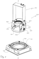
- a set of three reference axes have been assumed, i.e. in a longitudinal direction X-X, corresponding to the widthwise dimension of the spotlight; in a transverse direction Y-Y, corresponding to the depthwise dimension of the spotlight; and in a vertical direction Z-Z, at right angles to the other two directions; for easier description and with reference to the orientation shown in the figures, the longitudinal axis X-X is arranged coinciding with a first, horizontal, axis of rotation and the axis Z-Z is arranged coinciding with a second, vertical, axis of rotation.
- a motorized recessed spotlight according to the invention comprises essentially:
- Each wall 233,234 has a respective first eyelet 235 with a curved profile of predefined length open in the longitudinal direction X-X; only the second wall 234 has a second eyelet 236 with a curved profile of predefined length open in the longitudinal direction X-X as well as a through-hole 237 in turn formed in the longitudinal direction X-X;
- the rack 600 also moves parallel to the said eyelet while resting against the shoulder 237 and the pin 602 moves, along with it, the third tongue 223, forcing the light unit to perform a tilting movement resulting from its rotation about the pins 502 fixed to the first tongues 222 and a translational movement caused by the movement of the rack 600; the tilting action has an overall effect (see Figs. 7-9 ) such that the light beam always remains fully formed, without being partially obscured by the structure of the spotlight.
- the spotlight comprises:
- the spotlight is also formed by parts which are easy and inexpensive to produce and assemble and which may be easily installed at any user location using normal standardized connection means.
Landscapes
- Engineering & Computer Science (AREA)
- General Engineering & Computer Science (AREA)
- Non-Portable Lighting Devices Or Systems Thereof (AREA)
- Fastening Of Light Sources Or Lamp Holders (AREA)
- Arrangement Of Elements, Cooling, Sealing, Or The Like Of Lighting Devices (AREA)
- Forklifts And Lifting Vehicles (AREA)
Claims (11)
- Motorisierter Einbaustrahler, umfassend:- eine Leuchteinheit (1), in deren Innerem eine Stromversorgungseinrichtung und eine Lichtstrahlquelle angeordnet sind;- zumindest eine vertikale Achse (Z-2);- einen Sockel (100);- eine mechanische Trägereinheit (200), umfassend:-- eine Hülse (220), die einen zylindrischen Teil (221) umfasst, der mit einem Innengewinde (221) zum Eingriff mit der Lichteinheit (1) versehen ist; zumindest zwei erste Zungen (222), die sich parallel zu der vertikalen Richtung (Z-Z) erstrecken und mit einer jeweiligen Durchgangsbohrung (222a) in einer Längsrichtung (X-X) versehen sind; zumindest eine dritte Zunge (223), die sich parallel zu der vertikalen Richtung (ZZ) erstreckt und mit einer jeweiligen Durchgangsbohrung (222a) in der Längsrichtung (X-X) versehen ist, wobei die dritte Zunge in einem Winkelabstand in einer Ebene (X-Y) senkrecht zu der vertikalen Achse (Z-Z) von einer der beiden ersten Zungen (222) angeordnet ist;-- einen Ring (231), der in der Ebene (X-Y) liegt und mit einer radialen Ausnehmung (232) versehen ist, die in der vertikalen Richtung (Z-2) offen ist;-- zumindest eine erste Wand (233) und eine zweite Wand (234), die parallel zueinander in einer jeweiligen Ebene (Y-Z) parallel zu der vertikalen Achse (Z-Z) liegen, einander gegenüberliegend in der Längsrichtung (X-X) angeordnet sind und an dem Ring (231) befestigt sind;
wobei jede Wand (233, 234) eine jeweilige erste Öse (235) mit einem gekrümmten Profil von vordefinierter Länge aufweist, die in der Längsrichtung (X-X) offen ist; wobei die zweite Wand (234) eine zweite Öse (236) mit einem gekrümmten, in der Längsrichtung (X-X) offenen Profil vorgegebener Länge sowie eine Durchgangsbohrung (237) aufweist, die ihrerseits in der Längsrichtung (X-X) ausgebildet ist;- zumindest einen Motor (400) zum Kippen der Leuchteinheit (1), der an der zweiten Wand (234) der Trägereinheit (200) befestigt und mit einer Welle (401) versehen ist;- ein zylindrisches Ritzel (403) mit einer Längsachse (X-X) und radialen Zähnen (403a), das koaxial mit der Welle (401) des Motors (400) zum Kippen der Leuchteinheit (1) ist und darauf aufgekeilt ist;- eine Zahnstange (600) mit gekrümmtem Profil und geeigneter Länge, die mit Zähnen (601) versehen ist; wobei die Zahnstange eine durchgehende Ausnehmung (600a) mit einer Längsachse (X-X) zur Aufnahme eines Stifts (602) aufweist, der dazu ausgelegt ist, durch die zweite Öse (236) zur Befestigung der Zahnstange an der zweiten Wand (234) hindurchzugehen; wobei der Stift so angeordnet ist, dass er frei in der zweiten Öse zwischen den beiden gegenüberliegenden Enden derselben gleitet;wobei der Motor, das Ritzel, die Zahnstange und die Trägereinheit so angeordnet sind, dass sie eine Kippbewegung der Lichteinheit (1) um die Längsachse (X-X) bewirken, um eine konstante Breite des Lichtstrahls aufrechtzuerhalten, der in jeder Winkelposition des Scheinwerfers ausgesendet wird. - Strahler nach Anspruch 1, dadurch gekennzeichnet, dass der Motor zum Kippen der Leuchteinheit (1) an einer zugeordneten Halterung (402) in Form eines umgedrehten "L" angebracht ist, die eine Fläche (402a) in der Querrichtung (Y-X) und eine Fläche (402b) in der Vertikalrichtung (X-Z) aufweist, die jeweils mit Durchgangsbohrungen zur Aufnahme der Welle (401) des Motors (400) und zur Durchführung der Befestigung an der zweiten Wand (234) des Trägers (200) versehen sind.
- Strahler nach Anspruch 1 oder 2, dadurch gekennzeichnet, dass er eine von der zweiten Wand (234) nach außen vorstehende Schulter (237) aufweist, die mit einem gekrümmten Profil versehen ist, das dem der Zahnstange (600) entspricht, und die so angeordnet ist, dass die Seite der Zahnstange, die derjenigen der Zähne gegenüberliegt, auf der Schulter aufliegt.
- Strahler nach einem der vorhergehenden Ansprüche, dadurch gekennzeichnet, dass der Sockel (100) einen vertikal vertieften Sitz (110) zur Aufnahme einer ringförmigen Zahnstange (120) umfasst, die an dem Sockel befestigt ist.
- Strahler nach Anspruch 4, dadurch gekennzeichnet, dass er einen ersten Motor (300) zur Drehung um die vertikale Achse (Z-Z) umfasst, der an der ersten Wand (233) des Trägers (200) befestigt ist und dessen Welle (301) sich parallel zu der vertikalen Drehachse (Z-Z) des Strahlers erstreckt, wobei die Welle auf ein zylindrisches Zahnrad (303) aufgekeilt ist, das koaxial zu der Welle (301) ist und das dazu ausgelegt ist, mit den Zähnen (120) der Zahnstange (110) zu kämmen, um eine Drehung des Strahlers um die vertikale Achse (Z-Z) zu bewirken.
- Strahler nach Anspruch 5, dadurch gekennzeichnet, dass er eine Halterung (302) in Form eines umgedrehten "L" zum Tragen des ersten Motors (300) zur Drehung um die vertikale Achse (Z-Z) umfasst, die eine Fläche (302a) in der Längsrichtung (X-Y) und eine Fläche (302b) in der vertikalen Richtung (Y-Z) aufweist, wobei die Flächen jeweils mit Durchgangsbohrungen zur Aufnahme der Welle (301) des Motors (300) und zur Durchführung der Befestigung an der ersten Wand (233) des Trägers (200) versehen sind.
- Strahler nach einem der vorangegangenen Ansprüche, dadurch gekennzeichnet, dass er einen brückenförmigen Rahmen (210) umfasst, der zwei vertikale Pfosten (210a, 210b) umfasst, die an den sich gegenüberliegenden oberen Enden durch ein Querstück (210c) verbunden sind; wobei das freie Ende eines der zwei Pfosten eine Gabel (212) aufweist, deren Schenkel (212a), die sich in Querrichtung (Y-Y) gegenüberliegen, in Längsrichtung (X-X) jeweils eine Durchgangsbohrung (213) aufweisen, wobei der andere Schenkel (210a) ein freies Ende aufweist, das jeweils mit Durchgangsbohrungen (214) in Längsrichtung (X-X) versehen ist.
- Strahler nach einem der vorangegangenen Ansprüche, dadurch gekennzeichnet, dass er elektronische Mittel zum Empfang von Funksignalen umfasst, die mittels einer Fernsteuerung aus der Ferne ausgesendet werden und dazu ausgelegt sind, den Betrieb der Motoren (300, 400) zu steuern.
- Strahler nach einem der vorangegangenen Ansprüche, dadurch gekennzeichnet, dass sich der Motor zum Kippen der Leuchteinheit (1) parallel zu der vertikalen Drehachse (Z-Z) erstreckt.
- Strahler nach einem der vorangegangenen Ansprüche, dadurch gekennzeichnet, dass er Gleitreibungsmittel umfasst, die zwischen der Welle (401) des Motors zum Kippen der Leuchteinheit (1) und der Trägereinheit (200) angeordnet sind.
- Strahler nach einem der Ansprüche 5-10, dadurch gekennzeichnet, dass er Gleitreibungsmittel umfasst, die zwischen der Welle (301) des ersten Motors (300) für die Drehung um die vertikale Achse und der Trägereinheit (200) angeordnet sind.
Applications Claiming Priority (2)
| Application Number | Priority Date | Filing Date | Title |
|---|---|---|---|
| IT102018000003612A IT201800003612A1 (it) | 2018-03-15 | 2018-03-15 | Faretto da incasso motorizzato a cremagliera per la rotazione attorno ad un asse longitudinale |
| PCT/IB2019/051974 WO2019175752A1 (en) | 2018-03-15 | 2019-03-12 | Motorized recessed spotlight with rack for rotation about a longitudinal axis |
Publications (2)
| Publication Number | Publication Date |
|---|---|
| EP3765787A1 EP3765787A1 (de) | 2021-01-20 |
| EP3765787B1 true EP3765787B1 (de) | 2022-02-16 |
Family
ID=62530408
Family Applications (1)
| Application Number | Title | Priority Date | Filing Date |
|---|---|---|---|
| EP19716566.5A Active EP3765787B1 (de) | 2018-03-15 | 2019-03-12 | Motorisierter einbaustrahler mit rack für drehung um eine longitudinale achse |
Country Status (6)
| Country | Link |
|---|---|
| US (1) | US11092314B2 (de) |
| EP (1) | EP3765787B1 (de) |
| JP (1) | JP7216747B2 (de) |
| CN (1) | CN111868440B (de) |
| IT (1) | IT201800003612A1 (de) |
| WO (1) | WO2019175752A1 (de) |
Families Citing this family (4)
| Publication number | Priority date | Publication date | Assignee | Title |
|---|---|---|---|---|
| EP3983722A1 (de) * | 2019-06-11 | 2022-04-20 | Signify Holding B.V. | Verstellbare eingelassene beleuchtungsvorrichtung |
| KR102356664B1 (ko) * | 2021-03-29 | 2022-02-08 | (주)에스티라이팅 | 고천정 led 투광등 |
| CN114151765B (zh) * | 2021-11-29 | 2024-04-16 | 江苏伟世达车辆科技有限公司 | 一种便于排线的汽车前照灯灯体及其组装方法 |
| NL2031492B1 (en) * | 2022-03-16 | 2023-10-03 | Schreder Sa | Functional head system and method for securing the same |
Family Cites Families (25)
| Publication number | Priority date | Publication date | Assignee | Title |
|---|---|---|---|---|
| JPH0636127U (ja) * | 1992-10-13 | 1994-05-13 | 松下電工株式会社 | 埋込型照明器具 |
| US6036337A (en) * | 1998-05-22 | 2000-03-14 | Belfer; Bruce D. | Virtual axis lighting fixture |
| US6652124B2 (en) * | 2001-07-06 | 2003-11-25 | Cooper Technologies Company | Lamp-independent adjustable recessed light fixture |
| JP2004063089A (ja) | 2002-07-24 | 2004-02-26 | Ichikoh Ind Ltd | 乗り物用前照灯 |
| CN2653286Y (zh) * | 2003-09-02 | 2004-11-03 | 煜发有限公司 | 遥控式组合信号灯和聚光灯 |
| US7484866B1 (en) * | 2006-05-09 | 2009-02-03 | Genlyte Thomas Group Llc | Adjustable lighting fixture for sloped ceiling |
| US7625105B1 (en) * | 2007-09-18 | 2009-12-01 | Genlyte Thomas Group, Llc | Relamping cartridge assembly |
| US7559677B1 (en) * | 2007-09-30 | 2009-07-14 | Genlyte Thomas Group Llc | Recessed luminaire adjustment mechanism |
| US20100110698A1 (en) * | 2008-05-23 | 2010-05-06 | Usai, Llc | Universal Housing for Recessed Lighting |
| US7618166B1 (en) * | 2008-07-18 | 2009-11-17 | Number Eight Lighting Company | Light fixture lamp holder and modular trim assembly therefor |
| US8002425B2 (en) * | 2008-12-31 | 2011-08-23 | Hubbell Incorporated | Lighting assembly and lamp aiming device |
| US8727583B2 (en) * | 2008-12-31 | 2014-05-20 | Hubbell Incorporated | Lamp alignment assembly and lighting device |
| CN201983137U (zh) * | 2010-11-30 | 2011-09-21 | 福建新文行灯饰有限公司 | 一种新型遥控筒灯 |
| US9004728B2 (en) * | 2013-03-15 | 2015-04-14 | Abl Ip Holding Llc | Light assembly |
| US9657933B2 (en) * | 2014-02-03 | 2017-05-23 | Abl Ip Holding Llc | Interlaced heat sink for recessed light |
| US9599325B2 (en) * | 2014-02-27 | 2017-03-21 | Abl Ip Holding Llc | Recessed luminaire vise-like mounting system and method |
| JP6254069B2 (ja) * | 2014-11-05 | 2017-12-27 | ミネベアミツミ株式会社 | 角度調整装置および該角度調整装置を備える照明装置 |
| CA2958351A1 (en) * | 2016-02-16 | 2017-08-16 | RAB Lighting Inc. | Recessed lighting fixture with orientation adjusting apparatus |
| JP6438906B2 (ja) * | 2016-04-11 | 2018-12-19 | ミネベアミツミ株式会社 | 角度調整装置及び照明装置 |
| US10024523B2 (en) * | 2016-09-15 | 2018-07-17 | Usai, Llc | Adjustable light module for light fixture |
| CN206247100U (zh) * | 2016-10-21 | 2017-06-13 | 苏州瑞腾照明科技股份有限公司 | 一种灯体可转动的照明灯 |
| CN106439557B (zh) * | 2016-10-21 | 2018-05-15 | 苏州瑞腾照明科技股份有限公司 | 一种灯体可转动的照明灯 |
| TWM546473U (zh) * | 2017-03-07 | 2017-08-01 | 王茂森 | 一種具自動返回起始位置功能的探照燈 |
| CN106989326A (zh) * | 2017-05-27 | 2017-07-28 | 深圳市极成光电有限公司 | 灯具出光的调节机构 |
| US11215332B2 (en) * | 2019-05-02 | 2022-01-04 | Intense Lighting, Inc. | Lighting fixture having an adjustable optic system |
-
2018
- 2018-03-15 IT IT102018000003612A patent/IT201800003612A1/it unknown
-
2019
- 2019-03-12 US US16/979,991 patent/US11092314B2/en not_active Expired - Fee Related
- 2019-03-12 WO PCT/IB2019/051974 patent/WO2019175752A1/en not_active Ceased
- 2019-03-12 CN CN201980019012.XA patent/CN111868440B/zh not_active Expired - Fee Related
- 2019-03-12 EP EP19716566.5A patent/EP3765787B1/de active Active
- 2019-03-12 JP JP2020571915A patent/JP7216747B2/ja active Active
Also Published As
| Publication number | Publication date |
|---|---|
| CN111868440B (zh) | 2022-10-14 |
| JP2021515977A (ja) | 2021-06-24 |
| JP7216747B2 (ja) | 2023-02-01 |
| WO2019175752A1 (en) | 2019-09-19 |
| CN111868440A (zh) | 2020-10-30 |
| US11092314B2 (en) | 2021-08-17 |
| IT201800003612A1 (it) | 2019-09-15 |
| EP3765787A1 (de) | 2021-01-20 |
| US20210018163A1 (en) | 2021-01-21 |
Similar Documents
| Publication | Publication Date | Title |
|---|---|---|
| US11092314B2 (en) | Motorized recessed spotlight with rack for rotation about a longitudinal axis | |
| US9845849B2 (en) | Adjustable hanging device | |
| EP3132185B1 (de) | Motorisierte beleuchtungsanordnung | |
| EP3765786B1 (de) | Motorisierter einbaustrahler | |
| CN107148532A (zh) | 角度调整装置以及具备该角度调整装置的照明装置 | |
| AU2004225456B2 (en) | Adaptor with gimbal mounted sensor | |
| US11204157B2 (en) | Motorized spotlight with axially offset vertical arm | |
| WO2019175719A1 (en) | Device for moving a lamp body and motorized recessed spotlight comprising such a device | |
| GB2490893A (en) | Angularly adjustable mounting | |
| HK40044129B (en) | Motorized recessed spotlight with rack for rotation about a longitudinal axis | |
| HK40044129A (en) | Motorized recessed spotlight with rack for rotation about a longitudinal axis | |
| WO2019175757A1 (en) | Motorized recessed spotlight with link bar and crank drive system | |
| JP2018195386A (ja) | 取付部材、取付ユニット、照明装置及び照明ユニット | |
| WO2019175756A1 (en) | Motorized recessed spotlight | |
| KR200320712Y1 (ko) | 팬틸트카메라 | |
| JP4352835B2 (ja) | 人感センサユニットおよびこれを備えた照明器具 | |
| WO2019175753A1 (en) | Motorized recessed spotlight with spherical cap | |
| KR200403448Y1 (ko) | 감시카메라장치 | |
| HK40044130A (en) | Motorized recessed spotlight | |
| HK40044130B (en) | Motorized recessed spotlight | |
| CN210983673U (zh) | 感烟探测器的可自动调节云台以及感烟探测器 | |
| HK40044128A (en) | Motorized spotlight with axially offset vertical arm | |
| HK40044128B (en) | Motorized spotlight with axially offset vertical arm | |
| KR20240051138A (ko) | 조명 어셈블리 및 조명 어셈블리를 갖는 조명 시스템 | |
| HK1234132A1 (en) | Motorized light assembly |
Legal Events
| Date | Code | Title | Description |
|---|---|---|---|
| STAA | Information on the status of an ep patent application or granted ep patent |
Free format text: STATUS: UNKNOWN |
|
| STAA | Information on the status of an ep patent application or granted ep patent |
Free format text: STATUS: THE INTERNATIONAL PUBLICATION HAS BEEN MADE |
|
| PUAI | Public reference made under article 153(3) epc to a published international application that has entered the european phase |
Free format text: ORIGINAL CODE: 0009012 |
|
| STAA | Information on the status of an ep patent application or granted ep patent |
Free format text: STATUS: REQUEST FOR EXAMINATION WAS MADE |
|
| 17P | Request for examination filed |
Effective date: 20201006 |
|
| AK | Designated contracting states |
Kind code of ref document: A1 Designated state(s): AL AT BE BG CH CY CZ DE DK EE ES FI FR GB GR HR HU IE IS IT LI LT LU LV MC MK MT NL NO PL PT RO RS SE SI SK SM TR |
|
| AX | Request for extension of the european patent |
Extension state: BA ME |
|
| DAV | Request for validation of the european patent (deleted) | ||
| DAX | Request for extension of the european patent (deleted) | ||
| GRAJ | Information related to disapproval of communication of intention to grant by the applicant or resumption of examination proceedings by the epo deleted |
Free format text: ORIGINAL CODE: EPIDOSDIGR1 |
|
| STAA | Information on the status of an ep patent application or granted ep patent |
Free format text: STATUS: GRANT OF PATENT IS INTENDED |
|
| GRAP | Despatch of communication of intention to grant a patent |
Free format text: ORIGINAL CODE: EPIDOSNIGR1 |
|
| REG | Reference to a national code |
Ref country code: HK Ref legal event code: DE Ref document number: 40044129 Country of ref document: HK |
|
| INTG | Intention to grant announced |
Effective date: 20210917 |
|
| GRAS | Grant fee paid |
Free format text: ORIGINAL CODE: EPIDOSNIGR3 |
|
| GRAA | (expected) grant |
Free format text: ORIGINAL CODE: 0009210 |
|
| STAA | Information on the status of an ep patent application or granted ep patent |
Free format text: STATUS: THE PATENT HAS BEEN GRANTED |
|
| AK | Designated contracting states |
Kind code of ref document: B1 Designated state(s): AL AT BE BG CH CY CZ DE DK EE ES FI FR GB GR HR HU IE IS IT LI LT LU LV MC MK MT NL NO PL PT RO RS SE SI SK SM TR |
|
| REG | Reference to a national code |
Ref country code: GB Ref legal event code: FG4D |
|
| REG | Reference to a national code |
Ref country code: CH Ref legal event code: EP |
|
| REG | Reference to a national code |
Ref country code: DE Ref legal event code: R096 Ref document number: 602019011683 Country of ref document: DE |
|
| REG | Reference to a national code |
Ref country code: AT Ref legal event code: REF Ref document number: 1469090 Country of ref document: AT Kind code of ref document: T Effective date: 20220315 |
|
| REG | Reference to a national code |
Ref country code: IE Ref legal event code: FG4D |
|
| REG | Reference to a national code |
Ref country code: NL Ref legal event code: FP |
|
| REG | Reference to a national code |
Ref country code: LT Ref legal event code: MG9D |
|
| REG | Reference to a national code |
Ref country code: AT Ref legal event code: MK05 Ref document number: 1469090 Country of ref document: AT Kind code of ref document: T Effective date: 20220216 |
|
| PG25 | Lapsed in a contracting state [announced via postgrant information from national office to epo] |
Ref country code: SE Free format text: LAPSE BECAUSE OF FAILURE TO SUBMIT A TRANSLATION OF THE DESCRIPTION OR TO PAY THE FEE WITHIN THE PRESCRIBED TIME-LIMIT Effective date: 20220216 Ref country code: RS Free format text: LAPSE BECAUSE OF FAILURE TO SUBMIT A TRANSLATION OF THE DESCRIPTION OR TO PAY THE FEE WITHIN THE PRESCRIBED TIME-LIMIT Effective date: 20220216 Ref country code: PT Free format text: LAPSE BECAUSE OF FAILURE TO SUBMIT A TRANSLATION OF THE DESCRIPTION OR TO PAY THE FEE WITHIN THE PRESCRIBED TIME-LIMIT Effective date: 20220616 Ref country code: NO Free format text: LAPSE BECAUSE OF FAILURE TO SUBMIT A TRANSLATION OF THE DESCRIPTION OR TO PAY THE FEE WITHIN THE PRESCRIBED TIME-LIMIT Effective date: 20220516 Ref country code: LT Free format text: LAPSE BECAUSE OF FAILURE TO SUBMIT A TRANSLATION OF THE DESCRIPTION OR TO PAY THE FEE WITHIN THE PRESCRIBED TIME-LIMIT Effective date: 20220216 Ref country code: HR Free format text: LAPSE BECAUSE OF FAILURE TO SUBMIT A TRANSLATION OF THE DESCRIPTION OR TO PAY THE FEE WITHIN THE PRESCRIBED TIME-LIMIT Effective date: 20220216 Ref country code: ES Free format text: LAPSE BECAUSE OF FAILURE TO SUBMIT A TRANSLATION OF THE DESCRIPTION OR TO PAY THE FEE WITHIN THE PRESCRIBED TIME-LIMIT Effective date: 20220216 Ref country code: BG Free format text: LAPSE BECAUSE OF FAILURE TO SUBMIT A TRANSLATION OF THE DESCRIPTION OR TO PAY THE FEE WITHIN THE PRESCRIBED TIME-LIMIT Effective date: 20220516 |
|
| PG25 | Lapsed in a contracting state [announced via postgrant information from national office to epo] |
Ref country code: PL Free format text: LAPSE BECAUSE OF FAILURE TO SUBMIT A TRANSLATION OF THE DESCRIPTION OR TO PAY THE FEE WITHIN THE PRESCRIBED TIME-LIMIT Effective date: 20220216 Ref country code: LV Free format text: LAPSE BECAUSE OF FAILURE TO SUBMIT A TRANSLATION OF THE DESCRIPTION OR TO PAY THE FEE WITHIN THE PRESCRIBED TIME-LIMIT Effective date: 20220216 Ref country code: GR Free format text: LAPSE BECAUSE OF FAILURE TO SUBMIT A TRANSLATION OF THE DESCRIPTION OR TO PAY THE FEE WITHIN THE PRESCRIBED TIME-LIMIT Effective date: 20220517 Ref country code: FI Free format text: LAPSE BECAUSE OF FAILURE TO SUBMIT A TRANSLATION OF THE DESCRIPTION OR TO PAY THE FEE WITHIN THE PRESCRIBED TIME-LIMIT Effective date: 20220216 Ref country code: AT Free format text: LAPSE BECAUSE OF FAILURE TO SUBMIT A TRANSLATION OF THE DESCRIPTION OR TO PAY THE FEE WITHIN THE PRESCRIBED TIME-LIMIT Effective date: 20220216 |
|
| PG25 | Lapsed in a contracting state [announced via postgrant information from national office to epo] |
Ref country code: IS Free format text: LAPSE BECAUSE OF FAILURE TO SUBMIT A TRANSLATION OF THE DESCRIPTION OR TO PAY THE FEE WITHIN THE PRESCRIBED TIME-LIMIT Effective date: 20220617 |
|
| PG25 | Lapsed in a contracting state [announced via postgrant information from national office to epo] |
Ref country code: SM Free format text: LAPSE BECAUSE OF FAILURE TO SUBMIT A TRANSLATION OF THE DESCRIPTION OR TO PAY THE FEE WITHIN THE PRESCRIBED TIME-LIMIT Effective date: 20220216 Ref country code: SK Free format text: LAPSE BECAUSE OF FAILURE TO SUBMIT A TRANSLATION OF THE DESCRIPTION OR TO PAY THE FEE WITHIN THE PRESCRIBED TIME-LIMIT Effective date: 20220216 Ref country code: RO Free format text: LAPSE BECAUSE OF FAILURE TO SUBMIT A TRANSLATION OF THE DESCRIPTION OR TO PAY THE FEE WITHIN THE PRESCRIBED TIME-LIMIT Effective date: 20220216 Ref country code: EE Free format text: LAPSE BECAUSE OF FAILURE TO SUBMIT A TRANSLATION OF THE DESCRIPTION OR TO PAY THE FEE WITHIN THE PRESCRIBED TIME-LIMIT Effective date: 20220216 Ref country code: DK Free format text: LAPSE BECAUSE OF FAILURE TO SUBMIT A TRANSLATION OF THE DESCRIPTION OR TO PAY THE FEE WITHIN THE PRESCRIBED TIME-LIMIT Effective date: 20220216 Ref country code: CZ Free format text: LAPSE BECAUSE OF FAILURE TO SUBMIT A TRANSLATION OF THE DESCRIPTION OR TO PAY THE FEE WITHIN THE PRESCRIBED TIME-LIMIT Effective date: 20220216 |
|
| REG | Reference to a national code |
Ref country code: DE Ref legal event code: R097 Ref document number: 602019011683 Country of ref document: DE |
|
| PG25 | Lapsed in a contracting state [announced via postgrant information from national office to epo] |
Ref country code: MC Free format text: LAPSE BECAUSE OF FAILURE TO SUBMIT A TRANSLATION OF THE DESCRIPTION OR TO PAY THE FEE WITHIN THE PRESCRIBED TIME-LIMIT Effective date: 20220216 Ref country code: AL Free format text: LAPSE BECAUSE OF FAILURE TO SUBMIT A TRANSLATION OF THE DESCRIPTION OR TO PAY THE FEE WITHIN THE PRESCRIBED TIME-LIMIT Effective date: 20220216 |
|
| REG | Reference to a national code |
Ref country code: BE Ref legal event code: MM Effective date: 20220331 |
|
| PLBE | No opposition filed within time limit |
Free format text: ORIGINAL CODE: 0009261 |
|
| STAA | Information on the status of an ep patent application or granted ep patent |
Free format text: STATUS: NO OPPOSITION FILED WITHIN TIME LIMIT |
|
| 26N | No opposition filed |
Effective date: 20221117 |
|
| PG25 | Lapsed in a contracting state [announced via postgrant information from national office to epo] |
Ref country code: LU Free format text: LAPSE BECAUSE OF NON-PAYMENT OF DUE FEES Effective date: 20220312 Ref country code: IE Free format text: LAPSE BECAUSE OF NON-PAYMENT OF DUE FEES Effective date: 20220312 |
|
| PG25 | Lapsed in a contracting state [announced via postgrant information from national office to epo] |
Ref country code: SI Free format text: LAPSE BECAUSE OF FAILURE TO SUBMIT A TRANSLATION OF THE DESCRIPTION OR TO PAY THE FEE WITHIN THE PRESCRIBED TIME-LIMIT Effective date: 20220216 Ref country code: BE Free format text: LAPSE BECAUSE OF NON-PAYMENT OF DUE FEES Effective date: 20220331 |
|
| P01 | Opt-out of the competence of the unified patent court (upc) registered |
Effective date: 20230508 |
|
| PGFP | Annual fee paid to national office [announced via postgrant information from national office to epo] |
Ref country code: NL Payment date: 20240325 Year of fee payment: 6 |
|
| PG25 | Lapsed in a contracting state [announced via postgrant information from national office to epo] |
Ref country code: MK Free format text: LAPSE BECAUSE OF FAILURE TO SUBMIT A TRANSLATION OF THE DESCRIPTION OR TO PAY THE FEE WITHIN THE PRESCRIBED TIME-LIMIT Effective date: 20220216 Ref country code: CY Free format text: LAPSE BECAUSE OF FAILURE TO SUBMIT A TRANSLATION OF THE DESCRIPTION OR TO PAY THE FEE WITHIN THE PRESCRIBED TIME-LIMIT Effective date: 20220216 |
|
| PGFP | Annual fee paid to national office [announced via postgrant information from national office to epo] |
Ref country code: DE Payment date: 20240318 Year of fee payment: 6 Ref country code: GB Payment date: 20240325 Year of fee payment: 6 |
|
| PG25 | Lapsed in a contracting state [announced via postgrant information from national office to epo] |
Ref country code: HU Free format text: LAPSE BECAUSE OF FAILURE TO SUBMIT A TRANSLATION OF THE DESCRIPTION OR TO PAY THE FEE WITHIN THE PRESCRIBED TIME-LIMIT; INVALID AB INITIO Effective date: 20190312 |
|
| PGFP | Annual fee paid to national office [announced via postgrant information from national office to epo] |
Ref country code: IT Payment date: 20240325 Year of fee payment: 6 Ref country code: FR Payment date: 20240319 Year of fee payment: 6 |
|
| PGFP | Annual fee paid to national office [announced via postgrant information from national office to epo] |
Ref country code: CH Payment date: 20240401 Year of fee payment: 6 |
|
| PG25 | Lapsed in a contracting state [announced via postgrant information from national office to epo] |
Ref country code: MT Free format text: LAPSE BECAUSE OF FAILURE TO SUBMIT A TRANSLATION OF THE DESCRIPTION OR TO PAY THE FEE WITHIN THE PRESCRIBED TIME-LIMIT Effective date: 20220216 |
|
| REG | Reference to a national code |
Ref country code: DE Ref legal event code: R119 Ref document number: 602019011683 Country of ref document: DE |
|
| REG | Reference to a national code |
Ref country code: CH Ref legal event code: H13 Free format text: ST27 STATUS EVENT CODE: U-0-0-H10-H13 (AS PROVIDED BY THE NATIONAL OFFICE) Effective date: 20251023 |
|
| REG | Reference to a national code |
Ref country code: NL Ref legal event code: MM Effective date: 20250401 |
|
| GBPC | Gb: european patent ceased through non-payment of renewal fee |
Effective date: 20250312 |
|
| PG25 | Lapsed in a contracting state [announced via postgrant information from national office to epo] |
Ref country code: TR Free format text: LAPSE BECAUSE OF FAILURE TO SUBMIT A TRANSLATION OF THE DESCRIPTION OR TO PAY THE FEE WITHIN THE PRESCRIBED TIME-LIMIT Effective date: 20220216 |
|
| PG25 | Lapsed in a contracting state [announced via postgrant information from national office to epo] |
Ref country code: NL Free format text: LAPSE BECAUSE OF NON-PAYMENT OF DUE FEES Effective date: 20250401 |
|
| PG25 | Lapsed in a contracting state [announced via postgrant information from national office to epo] |
Ref country code: DE Free format text: LAPSE BECAUSE OF NON-PAYMENT OF DUE FEES Effective date: 20251001 |
|
| PG25 | Lapsed in a contracting state [announced via postgrant information from national office to epo] |
Ref country code: GB Free format text: LAPSE BECAUSE OF NON-PAYMENT OF DUE FEES Effective date: 20250312 |
|
| PG25 | Lapsed in a contracting state [announced via postgrant information from national office to epo] |
Ref country code: FR Free format text: LAPSE BECAUSE OF NON-PAYMENT OF DUE FEES Effective date: 20250331 Ref country code: IT Free format text: LAPSE BECAUSE OF NON-PAYMENT OF DUE FEES Effective date: 20250312 |
|
| PG25 | Lapsed in a contracting state [announced via postgrant information from national office to epo] |
Ref country code: CH Free format text: LAPSE BECAUSE OF NON-PAYMENT OF DUE FEES Effective date: 20250331 |