EP3765757B1 - Wire-formed bearing cage - Google Patents
Wire-formed bearing cage Download PDFInfo
- Publication number
- EP3765757B1 EP3765757B1 EP19797425.6A EP19797425A EP3765757B1 EP 3765757 B1 EP3765757 B1 EP 3765757B1 EP 19797425 A EP19797425 A EP 19797425A EP 3765757 B1 EP3765757 B1 EP 3765757B1
- Authority
- EP
- European Patent Office
- Prior art keywords
- wire
- cage
- bearing cage
- axial end
- distal end
- Prior art date
- Legal status (The legal status is an assumption and is not a legal conclusion. Google has not performed a legal analysis and makes no representation as to the accuracy of the status listed.)
- Active
Links
Images


Classifications
-
- F—MECHANICAL ENGINEERING; LIGHTING; HEATING; WEAPONS; BLASTING
- F16—ENGINEERING ELEMENTS AND UNITS; GENERAL MEASURES FOR PRODUCING AND MAINTAINING EFFECTIVE FUNCTIONING OF MACHINES OR INSTALLATIONS; THERMAL INSULATION IN GENERAL
- F16C—SHAFTS; FLEXIBLE SHAFTS; ELEMENTS OR CRANKSHAFT MECHANISMS; ROTARY BODIES OTHER THAN GEARING ELEMENTS; BEARINGS
- F16C33/00—Parts of bearings; Special methods for making bearings or parts thereof
- F16C33/30—Parts of ball or roller bearings
- F16C33/46—Cages for rollers or needles
- F16C33/54—Cages for rollers or needles made from wire, strips, or sheet metal
- F16C33/541—Details of individual pockets, e.g. shape or roller retaining means
-
- F—MECHANICAL ENGINEERING; LIGHTING; HEATING; WEAPONS; BLASTING
- F16—ENGINEERING ELEMENTS AND UNITS; GENERAL MEASURES FOR PRODUCING AND MAINTAINING EFFECTIVE FUNCTIONING OF MACHINES OR INSTALLATIONS; THERMAL INSULATION IN GENERAL
- F16C—SHAFTS; FLEXIBLE SHAFTS; ELEMENTS OR CRANKSHAFT MECHANISMS; ROTARY BODIES OTHER THAN GEARING ELEMENTS; BEARINGS
- F16C33/00—Parts of bearings; Special methods for making bearings or parts thereof
- F16C33/30—Parts of ball or roller bearings
- F16C33/46—Cages for rollers or needles
- F16C33/54—Cages for rollers or needles made from wire, strips, or sheet metal
-
- F—MECHANICAL ENGINEERING; LIGHTING; HEATING; WEAPONS; BLASTING
- F16—ENGINEERING ELEMENTS AND UNITS; GENERAL MEASURES FOR PRODUCING AND MAINTAINING EFFECTIVE FUNCTIONING OF MACHINES OR INSTALLATIONS; THERMAL INSULATION IN GENERAL
- F16C—SHAFTS; FLEXIBLE SHAFTS; ELEMENTS OR CRANKSHAFT MECHANISMS; ROTARY BODIES OTHER THAN GEARING ELEMENTS; BEARINGS
- F16C2220/00—Shaping
- F16C2220/40—Shaping by deformation without removing material
-
- Y—GENERAL TAGGING OF NEW TECHNOLOGICAL DEVELOPMENTS; GENERAL TAGGING OF CROSS-SECTIONAL TECHNOLOGIES SPANNING OVER SEVERAL SECTIONS OF THE IPC; TECHNICAL SUBJECTS COVERED BY FORMER USPC CROSS-REFERENCE ART COLLECTIONS [XRACs] AND DIGESTS
- Y10—TECHNICAL SUBJECTS COVERED BY FORMER USPC
- Y10T—TECHNICAL SUBJECTS COVERED BY FORMER US CLASSIFICATION
- Y10T29/00—Metal working
- Y10T29/49—Method of mechanical manufacture
- Y10T29/49636—Process for making bearing or component thereof
- Y10T29/49643—Rotary bearing
- Y10T29/49679—Anti-friction bearing or component thereof
- Y10T29/49691—Cage making
Definitions
- the present invention relates to bearings, and more particularly to cages for rolling elements of bearings.
- the invention provides a bearing cage formed from a single piece of wire bent into shape.
- the cage includes a first axial end ring, a second axial end ring including a distal end of the single piece of wire, a plurality of axially-extending bridge portions between the first and second axial end rings, and a plurality of circumferentially-extending connection portions interconnecting adjacent bridge portions.
- the connection portions are alternately positioned adjacent the first and second axial end rings.
- the invention provides a bearing assembly including an inner ring, a plurality of rollers positioned on the inner ring, and the above-described bearing cage retaining the plurality of rollers on the inner ring.
- the invention provides a method of making a bearing cage from a single piece of wire.
- the method includes forming a first axial end ring, after forming the first axial end ring, deviating the wire from the first axial end ring and forming a plurality of axially-extending bridge portions and a plurality of circumferentially-extending connection portions to form a plurality of roller pockets, and after forming the plurality of roller pockets, deviating the wire from a last-formed roller pocket to form a second axial end ring.
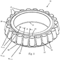
- Fig. 1 illustrates a portion of a tapered roller bearing assembly 10 including an inner ring or cone 14 defining thereon a raceway for supporting a plurality of rolling elements in the form of tapered rollers 18.
- the rollers 18 are retained in position on the inner ring 14 by a cage 22 embodying the present invention.
- the outer ring or cup of the bearing assembly 10 has been removed to reveal the rollers 18 and the cage 22.
- the cage 22 is formed from a single piece of material that is bent into the final form of the cage 22.
- the cage material is 1020 steel, round gauge wire of about forty thousandths of an inch (0.040 in.) in diameter, which can equate to 19 or 20-gauge wire.
- round gauge wire the contact between the cage 22 and the outer diameter surface of the rollers 18 is a line contact engagement due to the engagement between the generally cylindrical roller 18 and the cylindrical wire of the cage 22. This reduces friction between the rollers 18 and the cage 22 as compared to traditional stamped cages in which the planar stamped material presents a larger contact area with the rollers 18.
- the illustrated cage 22 has a reduced amount of material between rollers 18 and an overall lower weight as compared to traditional stamped cages. This enables the cage 22 to be designed to add one more roller 18 to the bearing assembly than if a traditional stamped cage were to be used for that same bearing assembly. By enabling the addition of an extra roller 18, the cage 22 increases the load-carrying capacity of the bearing assembly as compared to the same bearing assembly with a traditional stamped cage. In other embodiments, different wire material, cross-sectional shape, and size can be used to fit the particular bearing application.
- the single piece of wire is formed into the final-form cage 22 to include a first axial end ring 26, a second axial end ring 30, a plurality of axially-extending bridge portions 34 between the first and second axial end rings 26, 30, and a plurality of circumferentially-extending connection portions 38 interconnecting adjacent bridge portions 34.
- the connection portions 38 are alternately positioned adjacent the first and second axial end rings 26, 30. In the illustrated embodiment, the connection portions 38 are positioned adjacent the end rings 26, 30 at a location radially outside of the adjacent end rings 26, 30. In the illustrated embodiment, the connection portions are aligned with the end rings 26, 30 in the radial direction. Likewise, the bridge portions 34 are also positioned radially outside of the adjacent end rings 26, 30.
- the bridge portions 34 and connection portions 38 together form pockets 42 located radially inside of the roller pitch circle to retain the rollers 18 and hold them in position when placed on the inner ring 14, as shown in Fig. 1 .
- the bridge portions 34 and the connection portions 38 can be positioned adjacent the end rings 26, 30 at a location radially inside of the adjacent end rings 26, 30.
- the pockets 42 can alternatively be located radially outside of the roller pitch circle.
- each roller 18 has a roller end radius R Roller that defines a transition between the roller end face and the outer circumferential surface of the roller 18.
- the pockets 42 of the cage 22 each define cage corner radii R Corner at each internal corner that are smaller than the roller end radius R Roller.
- a roller end radius R Roller may be about 1.0 mm, while the cage corner radii R Corner may be about 0.5 mm.
- the wire gauge and material properties should be selected to enable achieving this relationship.
- the adjacent bridge portions 34 define a taper angle or total included angle A therebetween for receiving tapered rollers 18.
- the taper angle A can range from 1 degree to 50 degrees depending on the rollers 18. In one embodiment, the taper angle is between 4 and 20 degrees.
- the first and second axial end rings 26, 30 have different diameters D inner and D outer (see Fig. 3 ).
- the cage 22 has an axial length L (see Fig. 4 ).
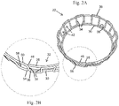
- the cage 22 is formed from the single piece of wire either manually using a fixture or by an automated wire forming machine. As best shown in Fig. 2B , a first distal end 46 of the wire starts, and is included in, the first axial end ring 26.
- the first axial end ring 26 is formed first, and once the wire is formed nearly to its 360 degree arc (to complete the first axial end ring 26), the wire deviates or bends radially outwardly at point 50 until it overlies or nearly overlies the distal end 46.
- the wire then deviates or bends axially to form a bridge portion 34, followed by a connection portion 38, followed by another bridge portion 34, and so on around the circumferential length of the cage 22 until all of the roller pockets 42 are formed.
- the wire deviates radially inwardly from the last-formed roller pocket 42, adjacent the interface of the first-formed bridge portion 34 and the first-formed connection portion 38, to begin forming the second axial end ring 30.
- the second axial end ring 30 is completed at the second distal end 58, which in the illustrated embodiment terminates adjacent the interface of the last-formed bridge portion 34 and the last-formed connection portion 38. Therefore, in the illustrated embodiment, the distal ends 46 and 58 are spaced apart in the circumferential direction by the circumferential length of one roller pocket 42, and are on opposite axial ends of the cage 22. In the case where the cage 22 is formed from a large coil of wire, the supply coil of wire can be cut after the cage 22 is formed to form the second distal end 58.
- Fig. 2C illustrates a variation of the bend arrangement shown in Fig. 2B .
- the first distal end 46' starts, and is included in, the first axial end ring 26'.
- the radially outward deviation at point 50' is the first of two radial bends, and a second deviation point 51' begins the formation of the first-formed connection portion 38' via a second radial bend.
- This first-formed connection portion 38' radially overlies or overlaps the first distal end 46' as shown, thereby eliminating any potential gap, and providing a potentially more robust design.
- the wire then deviates or bends axially to form a bridge portion 34', followed by a connection portion 38', followed by another bridge portion 34', and so on around the circumferential length of the cage 22' until all of the roller pockets 42' are formed.
- the dual-bend arrangement in Fig. 2C requires two radial-direction bends at points 50' and 51'. Therefore, a designer can determine whether the potentially added robustness of the design justifies the extra radial-direction bend.
- Figs. 2D illustrates a tapered roller bearing assembly similar to that shown in Fig. 2C , except that instead of having twenty-three rollers 18 (as illustrated in Figs. 1 and 2C ), the bearing assembly of Fig. 2D includes twenty-four rollers 18.
- Fig. 2E illustrates the cage 22" of the assembly of Fig. 2D .
- the cage 22" is similar to the cage 22' except that the first distal end 46" is at the end of a bridge portion 34" and is adjacent to the second distal end 58" at the second axial end ring 30". In other words, both distal ends 46" and 58" are adjacent the second axial end ring 30" (see Fig.
- the cage 22" has the second distal end 58" forming the end of the second axial end ring 30", but has the first distal end 46" defining an end of a bridge portion 34" that terminates near or in abutment with the second axial end ring 30" at the second distal end 58".
- this arrangement can be used for other cages designed to contain an even number of rollers 18, while the arrangements shown in Figs. 2B and 2C can be used for other cages designed to contain an odd number of rollers 18.
- first-formed connection portion 38" There is also more overlap of the first-formed connection portion 38" downstream of the bend point 51" with the first axial end ring 26". In other words, the first-formed connection portion 38" is longer than the first-formed connection portion 38' of cage 22'. To state it yet another way, the distance from the bend point 51" to the first bridge portion 34" extending off the first axial end ring 26" of the cage 22" is greater than the distance of the first bend point 51' to the first bridge portion 34' extending off the first axial end ring 26' of the cage 22'. This arrangement provides one additional pocket 42" for the added roller 18.
- no welding, brazing, or other joining technique or process is used to complete the cages 22, 22', or 22". Portions of the wire overlap, overlie, or abut other portions, but no welding, brazing, adhesive joining, or other mechanical joinder of the wire portions is performed. Likewise, the distal ends 46,46', 46" and 58, 58', and 58" are not mechanically joined to any other portion of the wire. This makes the formation of the cages 22, 22', 22" faster and less expensive than that of cages where welding, brazing, adhesives, or other joining techniques are required.
- Fig. 5 illustrates a cage 122 that is similar in construction to the cage 22, but is a cage for a cylindrical roller bearing assembly. Like parts have like reference numerals of the 100 series. Because the cage 122 is for a cylindrical bearing, the first and second axial end rings 126, 130 have the same diameter. Likewise, there is no taper angle between the bridge portions 134. The forming technique is the same as described above for the cage 22, but is modified to achieve the slightly different geometry of the cage 122.
- Figs. 6A and 6B illustrate a cage 222 that is like the cage 22 except that it does not include any axial end rings. Instead, the cage 222 includes only a meandering form that defines the bridge portions 234 and the connection portions 238. The distal ends of the wire can be welded together, or can merely abut (see Fig. 6B ).
- Figs. 7A and 7B to retain the tapered rollers 18 in an assembly, two of the cages 222 are used, radially offset from one another, and incremented circumferentially by one roller pocket such that each roller 18 has a connection portion 238 adjacent both ends to retain the rollers 18. In other words, one cage 222 is positioned above the roller pitch diameter and the other cage 222 is positioned below the roller pitch diameter. In this manner, no axial end rings are needed.
- the above cages are believed to perform as well or better than conventional stamped cages, and will be faster and less expensive to manufacture. In preliminary testing, no noticeable wear pattern was detected on the cages. No modifications to the rollers or the inner and outer bearing rings are needed for the bearing assemblies to incorporate these freefloating cages.
- the cages 22, 22', and 22" will be stiffer than the cage 222 due to the added end rings 26, 30, 26', 30', 26", 30". Therefore, some applications may favor the use of the stiffer cages 22, 22', 22", while other applications may favor the use of the less stiff cage 222.
Landscapes
- Engineering & Computer Science (AREA)
- General Engineering & Computer Science (AREA)
- Mechanical Engineering (AREA)
- Rolling Contact Bearings (AREA)
- Wire Processing (AREA)
- Mounting Of Bearings Or Others (AREA)
Description
- This application claims the benefit of
U.S. Provisional Patent Application No. 62/743,876 filed October 10, 2018 - The present invention relates to bearings, and more particularly to cages for rolling elements of bearings.
- In one aspect, the invention provides a bearing cage formed from a single piece of wire bent into shape. The cage includes a first axial end ring, a second axial end ring including a distal end of the single piece of wire, a plurality of axially-extending bridge portions between the first and second axial end rings, and a plurality of circumferentially-extending connection portions interconnecting adjacent bridge portions. The connection portions are alternately positioned adjacent the first and second axial end rings.
- In another aspect, the invention provides a bearing assembly including an inner ring, a plurality of rollers positioned on the inner ring, and the above-described bearing cage retaining the plurality of rollers on the inner ring.
- In another aspect the invention provides a method of making a bearing cage from a single piece of wire. The method includes forming a first axial end ring, after forming the first axial end ring, deviating the wire from the first axial end ring and forming a plurality of axially-extending bridge portions and a plurality of circumferentially-extending connection portions to form a plurality of roller pockets, and after forming the plurality of roller pockets, deviating the wire from a last-formed roller pocket to form a second axial end ring.
- Other aspects of the invention will become apparent by consideration of the detailed description and accompanying drawings.
-
-
Fig. 1 is a perspective view of a portion of a tapered roller bearing assembly illustrating the inner ring and a plurality of rolling elements supported on the inner ring by a cage embodying the present invention. -
Fig. 2A is a perspective view of the cage ofFig. 1 . -
Fig. 2B is an enlarged partial view ofFig. 2A showing the distal ends of the wire forming the cage. -
Fig. 2C is an enlarged partial view showing an alternative distal end arrangement of the wire forming the cage. -
Fig. 2D is an enlarged partial perspective view of a tapered roller bearing assembly similar to that ofFig. 2C but with one additional roller. -
Fig. 2E is an enlarged partial perspective view of the cage used with the tapered roller bearing assembly ofFig. 2D . -
Fig. 3 is an end view of the cage ofFig. 1 . -
Fig. 4 is a side view of the cage ofFig. 1 . -
Fig. 5 is a perspective view of an alternative cage for use with a cylindrical roller bearing assembly. -
Fig. 6A is a perspective view of yet another alternative cage without axial end rings. -
Fig. 6B is an enlarged partial perspective view of the cage ofFig. 6A -
Fig. 7A is a perspective view of a portion of a tapered roller bearing assembly illustrating the inner ring and a plurality of rolling elements supported on the inner ring by two of the cages shown inFig. 6A . -
Fig. 7B is an enlarged partial perspective view of the assembly ofFig. 7A . - Before any embodiments of the invention are explained in detail, it is to be understood that the invention is not limited in its application to the details of construction and the arrangement of components set forth in the following description or illustrated in the following drawings. The invention is capable of other embodiments and of being practiced or of being carried out in various ways.
-
Fig. 1 illustrates a portion of a tapered roller bearingassembly 10 including an inner ring orcone 14 defining thereon a raceway for supporting a plurality of rolling elements in the form oftapered rollers 18. Therollers 18 are retained in position on theinner ring 14 by acage 22 embodying the present invention. The outer ring or cup of thebearing assembly 10 has been removed to reveal therollers 18 and thecage 22. - Referring to
Figs. 1-4 , thecage 22 is formed from a single piece of material that is bent into the final form of thecage 22. In the illustrated embodiment, the cage material is 1020 steel, round gauge wire of about forty thousandths of an inch (0.040 in.) in diameter, which can equate to 19 or 20-gauge wire. By using round gauge wire, the contact between thecage 22 and the outer diameter surface of therollers 18 is a line contact engagement due to the engagement between the generallycylindrical roller 18 and the cylindrical wire of thecage 22. This reduces friction between therollers 18 and thecage 22 as compared to traditional stamped cages in which the planar stamped material presents a larger contact area with therollers 18. Furthermore, the illustratedcage 22 has a reduced amount of material betweenrollers 18 and an overall lower weight as compared to traditional stamped cages. This enables thecage 22 to be designed to add onemore roller 18 to the bearing assembly than if a traditional stamped cage were to be used for that same bearing assembly. By enabling the addition of anextra roller 18, thecage 22 increases the load-carrying capacity of the bearing assembly as compared to the same bearing assembly with a traditional stamped cage. In other embodiments, different wire material, cross-sectional shape, and size can be used to fit the particular bearing application. - The single piece of wire is formed into the final-
form cage 22 to include a firstaxial end ring 26, a secondaxial end ring 30, a plurality of axially-extendingbridge portions 34 between the first and secondaxial end rings connection portions 38 interconnectingadjacent bridge portions 34. Theconnection portions 38 are alternately positioned adjacent the first and secondaxial end rings connection portions 38 are positioned adjacent theend rings adjacent end rings end rings bridge portions 34 are also positioned radially outside of theadjacent end rings bridge portions 34 andconnection portions 38 together formpockets 42 located radially inside of the roller pitch circle to retain therollers 18 and hold them in position when placed on theinner ring 14, as shown inFig. 1 . However, in alternative constructions, thebridge portions 34 and theconnection portions 38 can be positioned adjacent theend rings adjacent end rings pockets 42 can alternatively be located radially outside of the roller pitch circle. - With reference to
Fig. 1 , eachroller 18 has a roller end radius RRoller that defines a transition between the roller end face and the outer circumferential surface of theroller 18. Thepockets 42 of thecage 22 each define cage corner radii RCorner at each internal corner that are smaller than the roller end radius RRoller. For example, a roller end radius RRoller may be about 1.0 mm, while the cage corner radii RCorner may be about 0.5 mm. The wire gauge and material properties should be selected to enable achieving this relationship. - With respect to the tapered
roller bearing assembly 10, theadjacent bridge portions 34 define a taper angle or total included angle A therebetween for receivingtapered rollers 18. The taper angle A can range from 1 degree to 50 degrees depending on therollers 18. In one embodiment, the taper angle is between 4 and 20 degrees. Additionally with a taperedroller bearing assembly 10, the first and second axial end rings 26, 30 have different diameters Dinner and Douter (seeFig. 3 ). Thecage 22 has an axial length L (seeFig. 4 ). - The
cage 22 is formed from the single piece of wire either manually using a fixture or by an automated wire forming machine. As best shown inFig. 2B , a firstdistal end 46 of the wire starts, and is included in, the firstaxial end ring 26. The firstaxial end ring 26 is formed first, and once the wire is formed nearly to its 360 degree arc (to complete the first axial end ring 26), the wire deviates or bends radially outwardly atpoint 50 until it overlies or nearly overlies thedistal end 46. The wire then deviates or bends axially to form abridge portion 34, followed by aconnection portion 38, followed by anotherbridge portion 34, and so on around the circumferential length of thecage 22 until all of the roller pockets 42 are formed. Next, atpoint 54, the wire deviates radially inwardly from the last-formedroller pocket 42, adjacent the interface of the first-formedbridge portion 34 and the first-formedconnection portion 38, to begin forming the secondaxial end ring 30. The secondaxial end ring 30 is completed at the seconddistal end 58, which in the illustrated embodiment terminates adjacent the interface of the last-formedbridge portion 34 and the last-formedconnection portion 38. Therefore, in the illustrated embodiment, the distal ends 46 and 58 are spaced apart in the circumferential direction by the circumferential length of oneroller pocket 42, and are on opposite axial ends of thecage 22. In the case where thecage 22 is formed from a large coil of wire, the supply coil of wire can be cut after thecage 22 is formed to form the seconddistal end 58. -
Fig. 2C illustrates a variation of the bend arrangement shown inFig. 2B . As inFig. 2B , the first distal end 46' starts, and is included in, the first axial end ring 26'. However, the radially outward deviation at point 50' is the first of two radial bends, and a second deviation point 51' begins the formation of the first-formed connection portion 38' via a second radial bend. This first-formed connection portion 38' radially overlies or overlaps the first distal end 46' as shown, thereby eliminating any potential gap, and providing a potentially more robust design. The wire then deviates or bends axially to form a bridge portion 34', followed by a connection portion 38', followed by another bridge portion 34', and so on around the circumferential length of the cage 22' until all of the roller pockets 42' are formed. Unlike the single radial bend/deviation atpoint 50 inFig. 2B , the dual-bend arrangement inFig. 2C requires two radial-direction bends at points 50' and 51'. Therefore, a designer can determine whether the potentially added robustness of the design justifies the extra radial-direction bend. -
Figs. 2D illustrates a tapered roller bearing assembly similar to that shown inFig. 2C , except that instead of having twenty-three rollers 18 (as illustrated inFigs. 1 and2C ), the bearing assembly ofFig. 2D includes twenty-fourrollers 18.Fig. 2E illustrates thecage 22" of the assembly ofFig. 2D . Thecage 22" is similar to the cage 22' except that the firstdistal end 46" is at the end of abridge portion 34" and is adjacent to the seconddistal end 58" at the secondaxial end ring 30". In other words, both distal ends 46" and 58" are adjacent the secondaxial end ring 30" (seeFig. 2E ) instead of one distal end defining the end of each respective axial end ring. Thus, unlike theother cages 22, 22', thecage 22" has the seconddistal end 58" forming the end of the secondaxial end ring 30", but has the firstdistal end 46" defining an end of abridge portion 34" that terminates near or in abutment with the secondaxial end ring 30" at the seconddistal end 58". In some embodiments, this arrangement can be used for other cages designed to contain an even number ofrollers 18, while the arrangements shown inFigs. 2B and2C can be used for other cages designed to contain an odd number ofrollers 18. There is also more overlap of the first-formedconnection portion 38" downstream of thebend point 51" with the firstaxial end ring 26". In other words, the first-formedconnection portion 38" is longer than the first-formed connection portion 38' of cage 22'. To state it yet another way, the distance from thebend point 51" to thefirst bridge portion 34" extending off the firstaxial end ring 26" of thecage 22" is greater than the distance of the first bend point 51' to the first bridge portion 34' extending off the first axial end ring 26' of the cage 22'. This arrangement provides oneadditional pocket 42" for the addedroller 18. - In the illustrated embodiments, no welding, brazing, or other joining technique or process is used to complete the
cages cages -
Fig. 5 illustrates acage 122 that is similar in construction to thecage 22, but is a cage for a cylindrical roller bearing assembly. Like parts have like reference numerals of the 100 series. Because thecage 122 is for a cylindrical bearing, the first and second axial end rings 126, 130 have the same diameter. Likewise, there is no taper angle between thebridge portions 134. The forming technique is the same as described above for thecage 22, but is modified to achieve the slightly different geometry of thecage 122. -
Figs. 6A and 6B illustrate acage 222 that is like thecage 22 except that it does not include any axial end rings. Instead, thecage 222 includes only a meandering form that defines thebridge portions 234 and theconnection portions 238. The distal ends of the wire can be welded together, or can merely abut (seeFig. 6B ). Referring now toFigs. 7A and 7B , to retain the taperedrollers 18 in an assembly, two of thecages 222 are used, radially offset from one another, and incremented circumferentially by one roller pocket such that eachroller 18 has aconnection portion 238 adjacent both ends to retain therollers 18. In other words, onecage 222 is positioned above the roller pitch diameter and theother cage 222 is positioned below the roller pitch diameter. In this manner, no axial end rings are needed. - The above cages are believed to perform as well or better than conventional stamped cages, and will be faster and less expensive to manufacture. In preliminary testing, no noticeable wear pattern was detected on the cages. No modifications to the rollers or the inner and outer bearing rings are needed for the bearing assemblies to incorporate these freefloating cages. The
cages cage 222 due to the added end rings 26, 30, 26', 30', 26", 30". Therefore, some applications may favor the use of thestiffer cages stiff cage 222. - Various features and advantages of the invention are set forth in the following claims.
Claims (15)
- A bearing cage (22) formed from a single piece of wire bent into shape, the cage comprising:a first axial end ring (26);a second axial end ring (30) including a distal end (58) of the single piece of wire;a plurality of axially-extending bridge portions (34) between the first and second axial end rings (26, 30); anda plurality of circumferentially-extending connection portions (38) interconnecting adjacent bridge portions (34), the connection portions (38) alternately positioned adjacent the first and second axial end rings (26, 30).
- The bearing cage of claim 1, wherein adjacent bridge portions (34) define a taper angle (A) therebetween to define pockets (42) for receiving tapered rollers, the taper angle (A) being between 1 and 50 degrees.
- The bearing cage of claim 2, wherein the taper angle (A) is between 4 and 20 degrees.
- The bearing cage of claim 1, wherein the first and second axial end rings (26, 30) have different diameters.
- The bearing cage of claim 1, wherein no mechanical welds, brazes, or joinders are made on the cage (22).
- The bearing cage of claim 1, wherein the bridge portions (34) and connection portions (38) are positioned radially outside of the first and second axial end rings (26, 30).
- The bearing cage of claim 1, wherein the distal end (58) of the single piece of wire included on the second end ring (30) is a second distal end of the wire, and wherein a first distal end (46) of the single piece of wire is on the first axial end ring (26).
- The bearing cage of claim 7, wherein adjacent bridge portions (34) define therebetween pockets (42) for receiving rollers, and wherein the bearing cage (22) includes an odd number of pockets (42).
- The bearing cage of claim 1, wherein the distal end (58") of the single piece of wire included on the second end ring (30") is a second distal end of the wire, and wherein a first distal end (46") of the single piece of wire is on a bridge portion (34") and is near or abutting the second axial end ring.
- The bearing cage of claim 9, wherein the first distal end (46") is near or abutting the second distal end (58").
- The bearing cage of claim 9, wherein adjacent bridge portions (34") define therebetween pockets (42) for receiving rollers, and wherein the bearing cage (22") includes an even number of pockets (42).
- A bearing assembly comprising:an inner ring (14);a plurality of rollers (18) positioned on the inner ring (14); andthe bearing cage of any one of claims 1 to 11 retaining the plurality of rollers (18) on the inner ring (14).
- The bearing assembly of claim 12, wherein the rollers (18) each include a roller end radius (RROLLER) that is greater than a cage corner (RCORNER) radius defined at each internal corner interface between adjacent bridge portions (34) and connection portions (38).
- A method of making a bearing cage (22) from a single piece of wire, the method comprising:forming a first axial end ring (26);after forming the first axial end ring (26), deviating the wire from the first axial end ring (26) and forming a plurality of axially-extending bridge portions (34) and a plurality of circumferentially-extending connection portions (38) to form a plurality of roller pockets (42); andafter forming the plurality of roller pockets (42), deviating the wire from a last-formed roller pocket (42) to form a second axial end ring (30).
- The method of claim 14, wherein no mechanical joining is performed on the single piece of wire.
Applications Claiming Priority (2)
| Application Number | Priority Date | Filing Date | Title |
|---|---|---|---|
| US201862743876P | 2018-10-10 | 2018-10-10 | |
| PCT/US2019/055345 WO2020076916A1 (en) | 2018-10-10 | 2019-10-09 | Wire-formed bearing cage |
Publications (2)
| Publication Number | Publication Date |
|---|---|
| EP3765757A1 EP3765757A1 (en) | 2021-01-20 |
| EP3765757B1 true EP3765757B1 (en) | 2022-04-06 |
Family
ID=68425269
Family Applications (1)
| Application Number | Title | Priority Date | Filing Date |
|---|---|---|---|
| EP19797425.6A Active EP3765757B1 (en) | 2018-10-10 | 2019-10-09 | Wire-formed bearing cage |
Country Status (6)
| Country | Link |
|---|---|
| US (1) | US10955004B2 (en) |
| EP (1) | EP3765757B1 (en) |
| JP (1) | JP6890731B2 (en) |
| CN (1) | CN112005020B (en) |
| PL (1) | PL3765757T3 (en) |
| WO (1) | WO2020076916A1 (en) |
Family Cites Families (23)
| Publication number | Priority date | Publication date | Assignee | Title |
|---|---|---|---|---|
| US1389385A (en) | 1921-08-30 | Roller-bearing | ||
| GB148627A (en) | 1919-04-26 | 1920-07-26 | Nordiska Kullager Ab | Improvements in thrust bearing ball cages of helically bent wires for withstanding centrifugal force |
| US1865796A (en) * | 1928-06-30 | 1932-07-05 | Frederick G Seifarth | Roller bearing |
| US1783141A (en) | 1929-02-27 | 1930-11-25 | Hess Bright Mfg Co | Cage for ball bearings |
| GB584120A (en) * | 1944-10-11 | 1947-01-07 | Timken Roller Bearing Co | Improvements in cages for roller bearings |
| SE333494B (en) | 1969-05-16 | 1971-03-15 | Skf Svenska Kullagerfab Ab | |
| DE2150982A1 (en) | 1971-10-13 | 1973-04-19 | Schaeffler Ohg Industriewerk | WIRE CAGE FOR ROLLER BEARING |
| SU563517A1 (en) * | 1974-08-23 | 1977-06-30 | 9-Й Гсударственный Подшипниковый Завод Им.Вв.Куйбышева | Manufacturing of roller bearings separators |
| US4212095A (en) | 1978-02-13 | 1980-07-15 | Warchol Henry A | Bearing components and methods of making same |
| GB1604570A (en) | 1978-05-31 | 1981-12-09 | Ransome Hoffmann Pollard | Production and assembly of rolling element bearings |
| CN2152114Y (en) * | 1992-07-01 | 1994-01-05 | 淮南轴承厂 | Cage support frame for conical roller bearing |
| US5291655A (en) | 1993-01-29 | 1994-03-08 | The Torrington Company | Method of making a one-piece ball bearing retainer |
| US5404642A (en) | 1994-01-31 | 1995-04-11 | The Torrington Company | Method of assembling a bearing |
| JP4340547B2 (en) * | 2004-01-14 | 2009-10-07 | 日本トムソン株式会社 | Guide unit with built-in roller chain |
| US7611289B2 (en) * | 2004-09-24 | 2009-11-03 | Ntn Corporation | Rollers with retainer |
| DE102008014552B4 (en) * | 2007-03-23 | 2011-02-03 | Ab Skf | Wire cage for roller bearings |
| DE102010042090A1 (en) * | 2010-10-07 | 2012-04-12 | Aktiebolaget Skf | Rolling bearing with a gap seal |
| GB2533554B (en) * | 2014-12-15 | 2018-06-20 | Skf Ab | Seal for a roller bearing having a wire cage |
| WO2016147808A1 (en) * | 2015-03-16 | 2016-09-22 | Ntn株式会社 | Retainer for tapered roller bearing |
| DE102015213115A1 (en) * | 2015-07-14 | 2017-01-19 | Schaeffler Technologies AG & Co. KG | Wire cage for a rolling bearing and manufacturing method therefor |
| FR3042561B1 (en) * | 2015-10-16 | 2018-03-30 | Aktiebolaget Skf | BEARING COMPRISING A CAGE WITH A WIRE AND A SEAL |
| DE102017104705A1 (en) * | 2017-03-07 | 2018-09-13 | Schaeffler Technologies AG & Co. KG | Rolling bearing cage |
| DE202017103280U1 (en) * | 2017-05-31 | 2017-07-19 | Aktiebolaget Skf | Ring or ring segment |
-
2019
- 2019-10-09 WO PCT/US2019/055345 patent/WO2020076916A1/en not_active Ceased
- 2019-10-09 JP JP2020555517A patent/JP6890731B2/en active Active
- 2019-10-09 EP EP19797425.6A patent/EP3765757B1/en active Active
- 2019-10-09 PL PL19797425.6T patent/PL3765757T3/en unknown
- 2019-10-09 US US16/971,029 patent/US10955004B2/en active Active
- 2019-10-09 CN CN201980028875.3A patent/CN112005020B/en active Active
Also Published As
| Publication number | Publication date |
|---|---|
| PL3765757T3 (en) | 2022-08-29 |
| US20210003174A1 (en) | 2021-01-07 |
| EP3765757A1 (en) | 2021-01-20 |
| US10955004B2 (en) | 2021-03-23 |
| CN112005020A (en) | 2020-11-27 |
| CN112005020B (en) | 2021-12-14 |
| JP6890731B2 (en) | 2021-06-18 |
| WO2020076916A1 (en) | 2020-04-16 |
| JP2021515162A (en) | 2021-06-17 |
Similar Documents
| Publication | Publication Date | Title |
|---|---|---|
| EP1757823B2 (en) | Tapered roller bearing | |
| US5044783A (en) | Pocket surface for separator for ball bearings | |
| US10654090B2 (en) | Method of forming a roller element bearing cage comprising a supporting frame and a reinforcing frame | |
| JP2010525272A (en) | Rolling bearing cage assembled from multiple components | |
| CN104246253A (en) | Rolling element guide cage and method for producing same | |
| CN103415717A (en) | Rolling element cage | |
| CN103443485A (en) | Rolling-element bearing cage and method for producing a rolling-element bearing cage | |
| CN105275996A (en) | Crankshaft or connecting-rod bearing assembly of an internal combustion engine | |
| US20160003298A1 (en) | Cage portion and method for the production thereof | |
| US7766555B2 (en) | Roller bearing and method of assembling the same | |
| JP2019173919A (en) | Cage for self-aligning roller bearing | |
| CN103807302A (en) | Cage for thrust roller bearing | |
| US2294289A (en) | Method of making bearing retaining means | |
| CN104565021A (en) | Tapered roller bearing | |
| US10955004B2 (en) | Wire-formed bearing cage | |
| JP4278342B2 (en) | Cylindrical roller bearing | |
| US20050094913A1 (en) | Unitized bearing assembly | |
| US20110222811A1 (en) | Retainer-equipped roller | |
| JPH03157518A (en) | Rolling bearing holder | |
| US10422383B2 (en) | Bearing cage, rolling element bearing and method | |
| US9587675B2 (en) | Bearing shell with alignment projecting feature | |
| US10767699B2 (en) | Bearing cage, rolling element bearing and method | |
| JP4344630B2 (en) | Constant velocity joint and its assembly method | |
| KR20200093753A (en) | A Cage For Ball Bearing | |
| JP2009014164A (en) | Manufacturing method of cylindrical member with flange |
Legal Events
| Date | Code | Title | Description |
|---|---|---|---|
| STAA | Information on the status of an ep patent application or granted ep patent |
Free format text: STATUS: UNKNOWN |
|
| STAA | Information on the status of an ep patent application or granted ep patent |
Free format text: STATUS: THE INTERNATIONAL PUBLICATION HAS BEEN MADE |
|
| PUAI | Public reference made under article 153(3) epc to a published international application that has entered the european phase |
Free format text: ORIGINAL CODE: 0009012 |
|
| STAA | Information on the status of an ep patent application or granted ep patent |
Free format text: STATUS: REQUEST FOR EXAMINATION WAS MADE |
|
| 17P | Request for examination filed |
Effective date: 20201013 |
|
| AK | Designated contracting states |
Kind code of ref document: A1 Designated state(s): AL AT BE BG CH CY CZ DE DK EE ES FI FR GB GR HR HU IE IS IT LI LT LU LV MC MK MT NL NO PL PT RO RS SE SI SK SM TR |
|
| AX | Request for extension of the european patent |
Extension state: BA ME |
|
| GRAP | Despatch of communication of intention to grant a patent |
Free format text: ORIGINAL CODE: EPIDOSNIGR1 |
|
| STAA | Information on the status of an ep patent application or granted ep patent |
Free format text: STATUS: GRANT OF PATENT IS INTENDED |
|
| INTG | Intention to grant announced |
Effective date: 20211110 |
|
| DAV | Request for validation of the european patent (deleted) | ||
| DAX | Request for extension of the european patent (deleted) | ||
| GRAS | Grant fee paid |
Free format text: ORIGINAL CODE: EPIDOSNIGR3 |
|
| GRAA | (expected) grant |
Free format text: ORIGINAL CODE: 0009210 |
|
| STAA | Information on the status of an ep patent application or granted ep patent |
Free format text: STATUS: THE PATENT HAS BEEN GRANTED |
|
| AK | Designated contracting states |
Kind code of ref document: B1 Designated state(s): AL AT BE BG CH CY CZ DE DK EE ES FI FR GB GR HR HU IE IS IT LI LT LU LV MC MK MT NL NO PL PT RO RS SE SI SK SM TR |
|
| REG | Reference to a national code |
Ref country code: GB Ref legal event code: FG4D |
|
| REG | Reference to a national code |
Ref country code: CH Ref legal event code: EP |
|
| REG | Reference to a national code |
Ref country code: AT Ref legal event code: REF Ref document number: 1481611 Country of ref document: AT Kind code of ref document: T Effective date: 20220415 |
|
| REG | Reference to a national code |
Ref country code: DE Ref legal event code: R096 Ref document number: 602019013539 Country of ref document: DE |
|
| REG | Reference to a national code |
Ref country code: IE Ref legal event code: FG4D |
|
| REG | Reference to a national code |
Ref country code: RO Ref legal event code: EPE |
|
| REG | Reference to a national code |
Ref country code: NL Ref legal event code: FP |
|
| REG | Reference to a national code |
Ref country code: SE Ref legal event code: TRGR |
|
| REG | Reference to a national code |
Ref country code: LT Ref legal event code: MG9D |
|
| REG | Reference to a national code |
Ref country code: AT Ref legal event code: MK05 Ref document number: 1481611 Country of ref document: AT Kind code of ref document: T Effective date: 20220406 |
|
| PG25 | Lapsed in a contracting state [announced via postgrant information from national office to epo] |
Ref country code: PT Free format text: LAPSE BECAUSE OF FAILURE TO SUBMIT A TRANSLATION OF THE DESCRIPTION OR TO PAY THE FEE WITHIN THE PRESCRIBED TIME-LIMIT Effective date: 20220808 Ref country code: NO Free format text: LAPSE BECAUSE OF FAILURE TO SUBMIT A TRANSLATION OF THE DESCRIPTION OR TO PAY THE FEE WITHIN THE PRESCRIBED TIME-LIMIT Effective date: 20220706 Ref country code: LT Free format text: LAPSE BECAUSE OF FAILURE TO SUBMIT A TRANSLATION OF THE DESCRIPTION OR TO PAY THE FEE WITHIN THE PRESCRIBED TIME-LIMIT Effective date: 20220406 Ref country code: HR Free format text: LAPSE BECAUSE OF FAILURE TO SUBMIT A TRANSLATION OF THE DESCRIPTION OR TO PAY THE FEE WITHIN THE PRESCRIBED TIME-LIMIT Effective date: 20220406 Ref country code: GR Free format text: LAPSE BECAUSE OF FAILURE TO SUBMIT A TRANSLATION OF THE DESCRIPTION OR TO PAY THE FEE WITHIN THE PRESCRIBED TIME-LIMIT Effective date: 20220707 Ref country code: FI Free format text: LAPSE BECAUSE OF FAILURE TO SUBMIT A TRANSLATION OF THE DESCRIPTION OR TO PAY THE FEE WITHIN THE PRESCRIBED TIME-LIMIT Effective date: 20220406 Ref country code: ES Free format text: LAPSE BECAUSE OF FAILURE TO SUBMIT A TRANSLATION OF THE DESCRIPTION OR TO PAY THE FEE WITHIN THE PRESCRIBED TIME-LIMIT Effective date: 20220406 Ref country code: BG Free format text: LAPSE BECAUSE OF FAILURE TO SUBMIT A TRANSLATION OF THE DESCRIPTION OR TO PAY THE FEE WITHIN THE PRESCRIBED TIME-LIMIT Effective date: 20220706 Ref country code: AT Free format text: LAPSE BECAUSE OF FAILURE TO SUBMIT A TRANSLATION OF THE DESCRIPTION OR TO PAY THE FEE WITHIN THE PRESCRIBED TIME-LIMIT Effective date: 20220406 |
|
| PG25 | Lapsed in a contracting state [announced via postgrant information from national office to epo] |
Ref country code: RS Free format text: LAPSE BECAUSE OF FAILURE TO SUBMIT A TRANSLATION OF THE DESCRIPTION OR TO PAY THE FEE WITHIN THE PRESCRIBED TIME-LIMIT Effective date: 20220406 Ref country code: LV Free format text: LAPSE BECAUSE OF FAILURE TO SUBMIT A TRANSLATION OF THE DESCRIPTION OR TO PAY THE FEE WITHIN THE PRESCRIBED TIME-LIMIT Effective date: 20220406 Ref country code: IS Free format text: LAPSE BECAUSE OF FAILURE TO SUBMIT A TRANSLATION OF THE DESCRIPTION OR TO PAY THE FEE WITHIN THE PRESCRIBED TIME-LIMIT Effective date: 20220806 |
|
| REG | Reference to a national code |
Ref country code: DE Ref legal event code: R097 Ref document number: 602019013539 Country of ref document: DE |
|
| PG25 | Lapsed in a contracting state [announced via postgrant information from national office to epo] |
Ref country code: SM Free format text: LAPSE BECAUSE OF FAILURE TO SUBMIT A TRANSLATION OF THE DESCRIPTION OR TO PAY THE FEE WITHIN THE PRESCRIBED TIME-LIMIT Effective date: 20220406 Ref country code: SK Free format text: LAPSE BECAUSE OF FAILURE TO SUBMIT A TRANSLATION OF THE DESCRIPTION OR TO PAY THE FEE WITHIN THE PRESCRIBED TIME-LIMIT Effective date: 20220406 Ref country code: EE Free format text: LAPSE BECAUSE OF FAILURE TO SUBMIT A TRANSLATION OF THE DESCRIPTION OR TO PAY THE FEE WITHIN THE PRESCRIBED TIME-LIMIT Effective date: 20220406 Ref country code: DK Free format text: LAPSE BECAUSE OF FAILURE TO SUBMIT A TRANSLATION OF THE DESCRIPTION OR TO PAY THE FEE WITHIN THE PRESCRIBED TIME-LIMIT Effective date: 20220406 Ref country code: CZ Free format text: LAPSE BECAUSE OF FAILURE TO SUBMIT A TRANSLATION OF THE DESCRIPTION OR TO PAY THE FEE WITHIN THE PRESCRIBED TIME-LIMIT Effective date: 20220406 |
|
| PLBE | No opposition filed within time limit |
Free format text: ORIGINAL CODE: 0009261 |
|
| STAA | Information on the status of an ep patent application or granted ep patent |
Free format text: STATUS: NO OPPOSITION FILED WITHIN TIME LIMIT |
|
| 26N | No opposition filed |
Effective date: 20230110 |
|
| PG25 | Lapsed in a contracting state [announced via postgrant information from national office to epo] |
Ref country code: AL Free format text: LAPSE BECAUSE OF FAILURE TO SUBMIT A TRANSLATION OF THE DESCRIPTION OR TO PAY THE FEE WITHIN THE PRESCRIBED TIME-LIMIT Effective date: 20220406 |
|
| PG25 | Lapsed in a contracting state [announced via postgrant information from national office to epo] |
Ref country code: SI Free format text: LAPSE BECAUSE OF FAILURE TO SUBMIT A TRANSLATION OF THE DESCRIPTION OR TO PAY THE FEE WITHIN THE PRESCRIBED TIME-LIMIT Effective date: 20220406 Ref country code: MC Free format text: LAPSE BECAUSE OF FAILURE TO SUBMIT A TRANSLATION OF THE DESCRIPTION OR TO PAY THE FEE WITHIN THE PRESCRIBED TIME-LIMIT Effective date: 20220406 |
|
| REG | Reference to a national code |
Ref country code: CH Ref legal event code: PL |
|
| REG | Reference to a national code |
Ref country code: BE Ref legal event code: MM Effective date: 20221031 |
|
| PG25 | Lapsed in a contracting state [announced via postgrant information from national office to epo] |
Ref country code: LU Free format text: LAPSE BECAUSE OF NON-PAYMENT OF DUE FEES Effective date: 20221009 |
|
| P01 | Opt-out of the competence of the unified patent court (upc) registered |
Effective date: 20230613 |
|
| PG25 | Lapsed in a contracting state [announced via postgrant information from national office to epo] |
Ref country code: LI Free format text: LAPSE BECAUSE OF NON-PAYMENT OF DUE FEES Effective date: 20221031 Ref country code: FR Free format text: LAPSE BECAUSE OF NON-PAYMENT OF DUE FEES Effective date: 20221031 Ref country code: CH Free format text: LAPSE BECAUSE OF NON-PAYMENT OF DUE FEES Effective date: 20221031 |
|
| PG25 | Lapsed in a contracting state [announced via postgrant information from national office to epo] |
Ref country code: BE Free format text: LAPSE BECAUSE OF NON-PAYMENT OF DUE FEES Effective date: 20221031 |
|
| PG25 | Lapsed in a contracting state [announced via postgrant information from national office to epo] |
Ref country code: IE Free format text: LAPSE BECAUSE OF NON-PAYMENT OF DUE FEES Effective date: 20221009 |
|
| PG25 | Lapsed in a contracting state [announced via postgrant information from national office to epo] |
Ref country code: CY Free format text: LAPSE BECAUSE OF FAILURE TO SUBMIT A TRANSLATION OF THE DESCRIPTION OR TO PAY THE FEE WITHIN THE PRESCRIBED TIME-LIMIT Effective date: 20220406 |
|
| PG25 | Lapsed in a contracting state [announced via postgrant information from national office to epo] |
Ref country code: MK Free format text: LAPSE BECAUSE OF FAILURE TO SUBMIT A TRANSLATION OF THE DESCRIPTION OR TO PAY THE FEE WITHIN THE PRESCRIBED TIME-LIMIT Effective date: 20220406 Ref country code: HU Free format text: LAPSE BECAUSE OF FAILURE TO SUBMIT A TRANSLATION OF THE DESCRIPTION OR TO PAY THE FEE WITHIN THE PRESCRIBED TIME-LIMIT; INVALID AB INITIO Effective date: 20191009 |
|
| PG25 | Lapsed in a contracting state [announced via postgrant information from national office to epo] |
Ref country code: MT Free format text: LAPSE BECAUSE OF FAILURE TO SUBMIT A TRANSLATION OF THE DESCRIPTION OR TO PAY THE FEE WITHIN THE PRESCRIBED TIME-LIMIT Effective date: 20220406 |
|
| PG25 | Lapsed in a contracting state [announced via postgrant information from national office to epo] |
Ref country code: BG Free format text: LAPSE BECAUSE OF FAILURE TO SUBMIT A TRANSLATION OF THE DESCRIPTION OR TO PAY THE FEE WITHIN THE PRESCRIBED TIME-LIMIT Effective date: 20220406 |
|
| PG25 | Lapsed in a contracting state [announced via postgrant information from national office to epo] |
Ref country code: BG Free format text: LAPSE BECAUSE OF FAILURE TO SUBMIT A TRANSLATION OF THE DESCRIPTION OR TO PAY THE FEE WITHIN THE PRESCRIBED TIME-LIMIT Effective date: 20220406 |
|
| PGFP | Annual fee paid to national office [announced via postgrant information from national office to epo] |
Ref country code: PL Payment date: 20250926 Year of fee payment: 7 |
|
| PGFP | Annual fee paid to national office [announced via postgrant information from national office to epo] |
Ref country code: NL Payment date: 20251021 Year of fee payment: 7 |
|
| PG25 | Lapsed in a contracting state [announced via postgrant information from national office to epo] |
Ref country code: TR Free format text: LAPSE BECAUSE OF FAILURE TO SUBMIT A TRANSLATION OF THE DESCRIPTION OR TO PAY THE FEE WITHIN THE PRESCRIBED TIME-LIMIT Effective date: 20220406 |
|
| PGFP | Annual fee paid to national office [announced via postgrant information from national office to epo] |
Ref country code: DE Payment date: 20251021 Year of fee payment: 7 |
|
| PGFP | Annual fee paid to national office [announced via postgrant information from national office to epo] |
Ref country code: GB Payment date: 20251022 Year of fee payment: 7 |
|
| PGFP | Annual fee paid to national office [announced via postgrant information from national office to epo] |
Ref country code: IT Payment date: 20251024 Year of fee payment: 7 |
|
| PGFP | Annual fee paid to national office [announced via postgrant information from national office to epo] |
Ref country code: SE Payment date: 20251021 Year of fee payment: 7 |
|
| PGFP | Annual fee paid to national office [announced via postgrant information from national office to epo] |
Ref country code: RO Payment date: 20251001 Year of fee payment: 7 |