EP3765707B1 - Flusssteuerungsvorrichtung und -verfahren - Google Patents
Flusssteuerungsvorrichtung und -verfahren Download PDFInfo
- Publication number
- EP3765707B1 EP3765707B1 EP19711050.5A EP19711050A EP3765707B1 EP 3765707 B1 EP3765707 B1 EP 3765707B1 EP 19711050 A EP19711050 A EP 19711050A EP 3765707 B1 EP3765707 B1 EP 3765707B1
- Authority
- EP
- European Patent Office
- Prior art keywords
- fluid
- fluid flow
- control device
- flow path
- flow
- Prior art date
- Legal status (The legal status is an assumption and is not a legal conclusion. Google has not performed a legal analysis and makes no representation as to the accuracy of the status listed.)
- Active
Links
Images


Classifications
-
- E—FIXED CONSTRUCTIONS
- E21—EARTH OR ROCK DRILLING; MINING
- E21B—EARTH OR ROCK DRILLING; OBTAINING OIL, GAS, WATER, SOLUBLE OR MELTABLE MATERIALS OR A SLURRY OF MINERALS FROM WELLS
- E21B43/00—Methods or apparatus for obtaining oil, gas, water, soluble or meltable materials or a slurry of minerals from wells
- E21B43/12—Methods or apparatus for controlling the flow of the obtained fluid to or in wells
-
- E—FIXED CONSTRUCTIONS
- E21—EARTH OR ROCK DRILLING; MINING
- E21B—EARTH OR ROCK DRILLING; OBTAINING OIL, GAS, WATER, SOLUBLE OR MELTABLE MATERIALS OR A SLURRY OF MINERALS FROM WELLS
- E21B34/00—Valve arrangements for boreholes or wells
- E21B34/06—Valve arrangements for boreholes or wells in wells
- E21B34/08—Valve arrangements for boreholes or wells in wells responsive to flow or pressure of the fluid obtained
-
- F—MECHANICAL ENGINEERING; LIGHTING; HEATING; WEAPONS; BLASTING
- F15—FLUID-PRESSURE ACTUATORS; HYDRAULICS OR PNEUMATICS IN GENERAL
- F15D—FLUID DYNAMICS, i.e. METHODS OR MEANS FOR INFLUENCING THE FLOW OF GASES OR LIQUIDS
- F15D1/00—Influencing flow of fluids
- F15D1/02—Influencing flow of fluids in pipes or conduits
- F15D1/025—Influencing flow of fluids in pipes or conduits by means of orifice or throttle elements
-
- F—MECHANICAL ENGINEERING; LIGHTING; HEATING; WEAPONS; BLASTING
- F16—ENGINEERING ELEMENTS AND UNITS; GENERAL MEASURES FOR PRODUCING AND MAINTAINING EFFECTIVE FUNCTIONING OF MACHINES OR INSTALLATIONS; THERMAL INSULATION IN GENERAL
- F16K—VALVES; TAPS; COCKS; ACTUATING-FLOATS; DEVICES FOR VENTING OR AERATING
- F16K15/00—Check valves
- F16K15/14—Check valves with flexible valve members
-
- F—MECHANICAL ENGINEERING; LIGHTING; HEATING; WEAPONS; BLASTING
- F16—ENGINEERING ELEMENTS AND UNITS; GENERAL MEASURES FOR PRODUCING AND MAINTAINING EFFECTIVE FUNCTIONING OF MACHINES OR INSTALLATIONS; THERMAL INSULATION IN GENERAL
- F16K—VALVES; TAPS; COCKS; ACTUATING-FLOATS; DEVICES FOR VENTING OR AERATING
- F16K31/00—Actuating devices; Operating means; Releasing devices
- F16K31/12—Actuating devices; Operating means; Releasing devices actuated by fluid
- F16K31/122—Actuating devices; Operating means; Releasing devices actuated by fluid the fluid acting on a piston
- F16K31/1221—Actuating devices; Operating means; Releasing devices actuated by fluid the fluid acting on a piston one side of the piston being spring-loaded
-
- G—PHYSICS
- G05—CONTROLLING; REGULATING
- G05D—SYSTEMS FOR CONTROLLING OR REGULATING NON-ELECTRIC VARIABLES
- G05D7/00—Control of flow
- G05D7/01—Control of flow without auxiliary power
- G05D7/0106—Control of flow without auxiliary power the sensing element being a flexible member, e.g. bellows, diaphragm, capsule
- G05D7/012—Control of flow without auxiliary power the sensing element being a flexible member, e.g. bellows, diaphragm, capsule the sensing element being deformable and acting as a valve
-
- G—PHYSICS
- G05—CONTROLLING; REGULATING
- G05D—SYSTEMS FOR CONTROLLING OR REGULATING NON-ELECTRIC VARIABLES
- G05D7/00—Control of flow
- G05D7/01—Control of flow without auxiliary power
- G05D7/0126—Control of flow without auxiliary power the sensing element being a piston or plunger associated with one or more springs
- G05D7/0133—Control of flow without auxiliary power the sensing element being a piston or plunger associated with one or more springs within the flow-path
-
- E—FIXED CONSTRUCTIONS
- E21—EARTH OR ROCK DRILLING; MINING
- E21B—EARTH OR ROCK DRILLING; OBTAINING OIL, GAS, WATER, SOLUBLE OR MELTABLE MATERIALS OR A SLURRY OF MINERALS FROM WELLS
- E21B43/00—Methods or apparatus for obtaining oil, gas, water, soluble or meltable materials or a slurry of minerals from wells
- E21B43/32—Preventing gas- or water-coning phenomena, i.e. the formation of a conical column of gas or water around wells
Definitions
- the invention concerns the control of fluid flowing into a conduit. More specifically, the invention concerns a fluid flow control device, as well as a subsea production string and a method using such a fluid flow control device.
- the invention is useful in controlling flow of fluids from a subterranean hydrocarbon reservoir and into production strings.
- a well for producing hydrocarbons from a subterranean reservoir may extend through the reservoir in a number of orientations.
- reservoirs were accessed by drilling vertical wells. This is simple and straight-forward technique, but one which provides limited reservoir contact per well. Therefore, in order to access more of a reservoir per well, techniques and devices were developed to drill horizontal wells, i.e. turning the well from vertical to horizontal at a predetermined depth below the surface. So-called multi-lateral wells provide even greater access to - and contact with - the reservoir.
- a major challenge in the production of hydrocarbons from subterranean reservoirs is to increase the ability to recover the oil that is present in the reservoir.
- Today, only a part of the oil in a given reservoir is actually recovered and produced before the field is shut down. There are thus strong incentives for developing new technology to increase production and oil recovery.
- ICD Inflow Control Devices
- So-called autonomous ICDs comprise one or more valve elements and are normally open when oil is flowing through the device, but chokes the flow when and where water and/or gas enters the device.
- the annulus between the production string and the casing is typically divided into zones by annulus packers, which is known in the art.
- One or more ICDs or AICDs are then placed in each zone.
- ICDs A number of ICDs are known in the art. Relevant examples of ICDs or AICDs are found in patent publications US 5 435 393 (Brekke, et al. ), US 7 857 050 B2 (Zazovsky, et al. ), US 7 823 645 B2 (Henriksen, et al. ), US 2008/0041580 A1 (Freyer, et al. ), WO 2008/004875 A1 (Aakre, et al. ), US 2011/0067878 A1 (Aadnoy ), US 2008/0041582 A1 (Saetre, et al.
- the prior art AICD comprises a primary flow path and a secondary flow path arranged in fluid communication with the primary flow path.
- the secondary flow path further comprises two fluid flow restrictors serving as an inflow port and an outflow port from a chamber, respectively.
- the two flow restrictors are configured to generate different fluid flow characteristics.
- the secondary flow path is in fluid communication with the primary flow path.
- Such a configuration necessitates allocation of additional space within the housing, resulting in a longer axial length of the AICD.
- the configuration also makes it difficult to arrange filters at the fluid inlet to prevent plugging during operation. Such plugging is a well-known problem in the field.
- fluid flow restrictor such as a porous material
- porous materials have typically small openings, thereby creating a high risk of plugging due to fines (small particles).
- the purpose of the present invention is to overcome the shortcomings of the above mentioned prior art and to obtain further advantages.
- a fluid flow control device suitable for establishing a controllable fluid communication of a fluid flow (F) between an external fluid reservoir and a base pipe constituting part of a production string.
- the fluid flow control device comprises a primary flow path arranged inside a fluid control device housing.
- the primary flow path comprises a primary flow path inlet configured to guide a primary fluid flow ( F 0 ) constituting part of the fluid flow ( F ) at least partly axial into the fluid control device housing from the external fluid reservoir during operation and a primary flow path outlet configured to guide the primary fluid flow ( F 0 ) into the base pipe during operation.
- the fluid flow control device further includes a secondary flow path and a movable valve element arranged inside the fluid control device housing, at and/or within the primary flow path.
- the secondary flow path comprises at least one first fluid flow restrictor configured to generate a pressure decrease from a pressure p 1 upstream of the first fluid flow restrictor to a pressure p 2 downstream of the first fluid flow restrictor, at least one second fluid flow restrictor arranged downstream of the first fluid flow restrictor and configured to generate a pressure decrease from the pressure p 2 upstream of the second fluid flow restrictor to a pressure p 3 downstream of the second fluid flow restrictor and a chamber ( B ) arranged downstream the first fluid flow restrictor and upstream the second fluid flow restrictor.
- the movable valve element is configured to at least partly, preferably fully close the primary flow path for primary fluid flow ( F 0 ) when exposed to a pressure force from within the chamber ( B ) exceeding a threshold pressure force.
- the secondary flow path further comprises a secondary flow path inlet arranged within the fluid control device housing having a radial offset to the primary flow path at its entrance into the housing.
- the secondary flow path inlet is thus configured to guide a secondary fluid flow ( f ) constituting a remaining part of the fluid flow ( F ) from the fluid reservoir into the fluid control device housing.
- the fluid flow ( F ) from the external fluid reservoir is during operation divided into the primary fluid flow ( F 0 ) entering the housing via the first fluid path and the secondary fluid flow ( f ) entering the housing via the secondary fluid path.
- the primary fluid flow ( F 0 ) constitutes a major portion of the fluid flow ( F ) per unit time, for example more than 90 % or more than 95 %.
- Axial and radial direction is herein defined as the direction perpendicular and parallel to the longitudinal direction of the base pipe, respectively, i.e. the principal direction of fluid flow within the base pipe.
- the secondary flow path inlet is oriented such that the secondary fluid flow ( f ) flows axially or near axially into the fluid control device housing during operation.
- Near axially signifies that there may be a deviation from axial, for example a deviation of maximum 20 degrees from the axial axis.
- the first fluid flow restrictor is configured to generate either a laminar, or near laminar, fluid flow characteristic or a turbulent, or near turbulent, fluid flow characteristic
- the second fluid flow restrictor are configured to generate either a turbulent fluid flow characteristic or a laminar fluid flow characteristic being different from the fluid flow characteristic generated by the first fluid flow restrictor.
- Laminar flow is herein defined as a fluid flowing in parallel layers, with no or insignificant disruption between the layers.
- turbulent flow is herein defined as a fluid that undergoes irregular fluctuations, or mixing, i.e. where the speed of the fluid at a point is continuously undergoing changes in both magnitude and direction.
- the flow control device further comprises an inlet bushing arranged axially within the flow control device housing for guiding the primary fluid flow ( F 0 ) therethrough during operation and a first ring-shaped disc arranged axially beneath the secondary flow path inlet with its centered opening around the inlet bushing.
- the inlet bushing and the first ring-shaped disc may be separate or form an integrate part.
- the first ring-shaped disc may comprise an axial, or near axial, first locking edge running along the circumference of the inner center opening of the first ring-shaped disc.
- the disc may preferably also comprise an axial, or near axial, directed second locking edge along the outer circumference of the first ring-shaped disc having at least one opening configured to guide the secondary fluid flow ( f ) flowing through the secondary flow path inlet into the fluid flow restrictor during operation.
- one or more bushing seals are arranged between the inlet bushing and the first ring-shaped disc.
- 'beneath' signifies here an axial position relative to components of the fluid flow control device located at or near the inlet of the primary and secondary fluid flows ( F 0 , f ), e.g. an inlet bushing and/or an inlet filter.
- the fluid flow control device further comprises a filter arranged across the secondary flow path inlet for preventing, or at least significantly reducing, solid state particles within the fluid flow ( F ) from entering the secondary flow path, while at the same time allowing the primary fluid flow ( F 0 ) to flow unfiltered through the primary flow path inlet during operation.
- a filter arranged across the secondary flow path inlet for preventing, or at least significantly reducing, solid state particles within the fluid flow ( F ) from entering the secondary flow path, while at the same time allowing the primary fluid flow ( F 0 ) to flow unfiltered through the primary flow path inlet during operation.
- the filter may comprise at least one outer protrusions protruding radially outward from the outer circumference of the filter and at least one inner protrusion protruding radially inward from the inner circumference of the filter. These filter protrusions ensure a locking effect to the housing and the first ring-shaped disc, respectively.
- the first or the second fluid flow restrictor comprises a pipe of length L and a mean hydraulic diameter ⁇ D L > averaged across the length L, wherein the length ( L ) and the mean hydraulic diameter ( ⁇ D L >) are chosen to achieve a laminar flow characteristic flowing out of the one of the first and second fluid flow restrictors.
- the length ( L ) and the mean hydraulic diameter ( ⁇ D L >) are chosen to achieve a ratio between the length L and the mean hydraulic diameter ⁇ D L > , i.e. L / ⁇ D L > , that results in a Reynold number of the fluid flow ( RE ) being equal or less than 4000, preferably less than 3500, more preferably less than 3000 and even more preferably less than 2500.
- the first fluid flow restrictor comprises an interior outlet channel located inside the fluid control device housing being in fluid communication with the secondary flow path inlet, an exterior pipe of length L ⁇ located outside the fluid control device housing being in fluid communication with the interior outlet channel and an interior return channel located inside the fluid control device housing being in fluid communication with the exterior pipe.
- a section of the exterior pipe may be coiled, for example a multiple time around the base pipe of the production string.
- the secondary flow path comprises a secondary flow path outlet.
- more than 70 % of the length of the secondary flow path from the secondary flow path inlet and the secondary flow path outlet may be located outside the fluid control device housing, more preferably more than 80 % of the length and even more preferably more than 90 % of the length.
- both the secondary flow path outlet(s) and the second flow restrictor(s) are arranged outside the housing, while being in fluid communication with the pressure P2 within the chamber B of the housing. In this alternative or additional configuration, the flow out of the second flow restrictor(s) would then enter into the base pipe at pressure P3.
- the movable valve element comprises a lower disc having a disc surface facing towards the chamber B and an upper disc arranged with one disc surface facing towards the lower disc and the other disc surface facing toward the primary flow path inlet.
- the disc diameter of the upper disc may be smaller than the disc diameter of the lower disc.
- the axial transition between the lower disc and the upper disc may be smooth to avoid excessive fluid flow resistance of the primary fluid flow ( F 0 ) due to flow across sharp edges, pointed protrusions, etc.
- the disc diameter of the upper disc may preferably be at least equal to the minimum radial opening size of the primary flow path inlet.
- the section of the lower disc between the upper disc and the outer circumference of the lower disc may be flat relative to the radial direction of the fluid control device housing. In addition to further ensure non-interrupted primary fluid flow, the flat configuration also contribute to minimize the axial extent ( t AICD ) of the fluid control device housing.
- the fluid flow control device further comprises a second ring-shaped disc arranged with its centered opening around the outer circumference of the movable valve element.
- the second ring-shaped disc may comprise an axial directed edge extending along the outer circumference of the second ring-shaped disc and configured to create a fixed axial distance between the radially extending surface of the second ring-shaped facing towards the primary flow path inlet and an inner wall of the fluid control device housing.
- the axial directed edge displays at least one opening configured to guide the primary fluid flow ( F 0 ) flowing through the primary flow path inlet from the movable valve element towards the primary flow path outlet.
- the fluid flow control device further comprises a resilient member arranged axially beneath the surface of the movable valve element facing away from the primary flow path inlet.
- a part of the resilient member is preferably fixed to the interior walls of the fluid control device housing such that the movable valve element is an axial position when not exposure to a pressure force within the chamber B that ensures fluid flow between the primary flow path inlet and the primary flow path outlet.
- the first fluid flow restrictor comprises a multi-inlet pipe arranged in fluid communication downstream of the secondary flow path inlet, wherein the multi-inlet pipe displays at least two radially spaced apart inlets, for example having a first and second inlet arranged diagonally to each other across the primary flow path inlet.
- the shape of the multi-inlet pipe may as an example be an arc partly surrounding the primary flow path inlet.
- the first fluid flow restrictor comprises a multi-inlet pipe arranged with the fluid control device housing and in fluid communication with the secondary flow path inlet, an interior outlet channel arranged inside the fluid control device housing and in fluid communication with the multi-inlet pipe, an exterior pipe of length L ⁇ arranged at least partly outside the fluid control device housing and in fluid communication with the interior outlet channel and an interior return channel located inside the fluid control device housing and in fluid communication with the exterior pipe.
- the multi-inlet pipe displays at least two radially spaced apart inlets, for example arranged diagonally, or near diagonally, around the primary flow path inlet.
- a section of the exterior pipe may be coiled in order to achieve a long first fluid flow restrictor occupying a minimum amount of space.
- the invention also concerns a production string suitable for transport of hydrocarbons.
- the production string comprises base pipe, an enclosure arranged at the exterior wall of the base pipe having at least one enclosure input opening and a fluid flow control device in accordance with any of the above-mentioned features.
- the fluid flow control device is arranged into a through-going hole of the wall of the base pipe, and within the enclosure, such that a controllable fluid communication is obtained between the enclosure and the interior of the base pipe.
- the fluid communication takes place through one primary flow path inlet and into the base pipe via a plurality of primary flow path outlets.
- the enclosure is configured to provide an input chamber covering the at least one enclosure input opening of the enclosure as well as the primary flow path inlet and the secondary flow path inlet of the fluid flow control device.
- the first or the second fluid flow restrictors includes a pipe of length L and a mean hydraulic diameter ⁇ D L > averaged across the length L, for example a pipe with a constant diameter D.
- at least a part of the pipe is coiled at least 50 % around the outer circumference of the base pipe, more preferably at least 80 % around the outer circumference, even more preferably at least one time around the entire circumference, and even more preferably at least twice around the entire circumference.
- the invention concerns a method of controlling fluid flow ( F ) based on changes in fluid properties.
- the method uses a fluid flow control device in accordance with any one of the above-mentioned features and comprises the steps:
- a major portion of the length of the secondary flow path may preferably extend outside the fluid control device housing.
- the inventive flow control device stops unwanted fluids (e.g. water, gas, steam and CO 2 ) from entering production flow of a desired fluid (e.g. oil) while being robust, compact and fully autonomous. It is reversible in the sense that the valve device changes position as the properties (e.g. viscosity) of the fluid changes. That is, where for example the flow control device closes when the viscosity decreases (i.e. exposed to water or gas), it opens again when the viscosity increases (i.e. exposed to oil).
- unwanted fluids e.g. water, gas, steam and CO 2
- a desired fluid e.g. oil
- the valve device changes position as the properties (e.g. viscosity) of the fluid changes. That is, where for example the flow control device closes when the viscosity decreases (i.e. exposed to water or gas), it opens again when the viscosity increases (i.e. exposed to oil).
- the slim / compact design of the inventive flow control device avoids excessive protrusion into or out of the base pipe of the production string. This is a significant advantage over all the known AICDs described above.
- a flow control device protruding far out from the base pipe would make it difficult for oil and gas companies to use standard base pipes and bores used today. And due to both costs and technical challenges any changes in well proven design is normally undesirable. For example, a larger bore would result in increased cost and a bore with smaller diameter would result in increased pressure loss in the base pipe (well).
- protrusion into the base pipe should be avoided or reduced.
- One problem with protrusions into the base pipe is related to the fact that measurements or well intervention must be performed where smaller pipes / equipment are guided into base pipes / liners. Any protrusions such as protruding flow control devices makes such operations difficult or even impossible.
- Figure 1 illustrates how a fluid F,f flows through a fluid flow inlet 1 into a conduit 2 at a first pressure p 1 , further through a first fluid flow restrictor 3 and into a chamber B where it attains a second pressure p 2 , and then flows through a second fluid flow restrictor 4 before it exits the conduit 2 through a fluid flow outlet 5 at a third pressure p 3 .
- the fluid flow rate and fluid properties e.g. viscosity, density
- the pressures ( p 1 , p 2 , p 3 ) are also constant, and p 1 , > p 2 , > p 3 .
- the first fluid flow restrictor 3 is a coiled pipe and the second fluid flow restrictor 4 is an orifice.
- the coiled pipe may have any cross-sectional shape such as circular shape, rectangular shape, triangular shape, etc.
- ⁇ P f D ⁇ ⁇ ⁇ ⁇ v ⁇ 2 2 ⁇ L D L
- a large ratio L / D corresponds to a large pressure drop ⁇ P (from p 1 to p 2 in Fig. 1A ) when a fluid F,f is flowing through the conduit 2.
- the change in pressure ( ⁇ P ) across the coiled pipe is seen to be proportional to the fluid viscosity ( ⁇ ) , as well as the ratio L/D 4 .
- ⁇ P K orifice ⁇ ⁇ ⁇ 2 2
- the fluid pressure p 2 in the chamber B i.e. between the coiled pipe 3 and the orifice 4, will change if the properties (viscosity or density) of the fluid changes.
- a first (low) value for p 2 is formed with a flow of fluid having a high fluid viscosity ( ⁇ high ) and a second (high) value for p 2 is formed with a flow of fluid having a low fluid viscosity ( ⁇ low ).
- the difference between the values for p 2 ( ⁇ P 2 ) occurring when the fluid properties changes may be used to perform work, for example actuate an actuator 6, which in turn may move a piston 9 acting as a valve element 9, possibly via hydraulic and/or electrical and/or mechanical transmission means 10 (see Fig. 3 ).
- the present invention utilizes the change in pressure ( ⁇ P 2 ) that occurs between two different flow restrictors when subjected to fluids of different properties, e.g. oil and water.
- These properties may for example be viscosity, density or both.
- Figure 3A and 3B are schematics illustrating two embodiments of the principle described above.
- Figure 3A illustrates a first embodiment of the inventive flow control device 100 in its basic form (i.e. where seals, gaskets and other required or recommended ancillary parts known in the art are omitted).
- a fluid flow ( F ) enters a fluid control device housing 8 via two fluid paths 2,7; a primary flow path (primary conduit) 2 having a primary flow path inlet 1 and a secondary flow path (secondary conduit) 7 having a secondary flow path inlet 11.
- the major portion ( F 0 ) of the fluid flow ( F ) hereinafter referred to as the primary fluid flow, flows through the primary conduit 2 and an initially open valve element 9.
- a first fluid flow restrictor 3 in the form of a coiled, thin tube of length L and diameter D
- a second fluid flow restrictor 4 in the form of an orifice
- the second pressure p 2 in a chamber B located in the secondary conduit 7 between the two fluid restrictors 3,4 also changes. For example, if a flow of oil is replaced by water or gas, the viscosity decreases and the second pressure p 2 increases as explained above with reference to Figs. 1 and 2 .
- Figure 3A furthermore shows (schematically) an actuator 6 arranged within, or coupled to, the chamber B .
- the actuator 6 is connected via transmission means 10 (e.g. via a hydraulic linkage, a mechanical linkage and/or a signal cable) to the piston / valve element 9.
- the actuator 10 can be of any form that enable actuation of the piston / valve element 9, e.g. the surface of a valve piston being exposed to the force generated by the induced pressure ⁇ P 2 such as the surface facing the chamber B .
- the conduits 2,7 and the fluid flow restrictors 3,4 may be configured and dimensioned such that (when breakthrough is to be prevented) the piston / valve element 9 automatically closes when the viscosity ( ⁇ ) of the fluid ( F ) drops below a predetermined level.
- this device 100 prevents unwanted water and/or gas inflow into a production string 101 (see Fig. 4 ).
- Figure 3B shows schematically a second embodiment of the invented flow control device 100.
- the second embodiment is identical to the first embodiment with the exception that the secondary flow path 7 is not in fluid communication with the primary flow path 2. Instead, both enters and exits the housing 8 via separate flow paths.
- the primary fluid flow ( F 0 ) enters the primary flow path 2 from inlet 1 and exits through primary flow path outlet 5, while the secondary fluid flow ( f ) enters the secondary flow path 7 from inlet 11 and exits through a separate secondary flow path outlet 12.
- the operational principle is however the same as for the first embodiment, i.e.
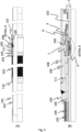
- Figures 4A and 4B show cross sectional drawings of a complete flow control device 100 in accordance with the invention.
- Fig. 4A shows the flow control device 100 mounted into a production string 101 and
- Fig. 4B shows in further detail the area of the production string 101 framed into a dashed rectangle (detail A).
- the production string 101 further comprises a base pipe 102 into which the flow control device 100 is installed, a sand screen 103 surrounding the base pipe 102 in order to prevent large solid particles such as grains of sand or debris to enter the base pipe 102, an outer sleeve 110 fixing one axial end of the sand screen 103 to the base pipe 102, a first inner sleeve 104 configured to fix both the other axial end of the sand screen 103 onto the base pipe 102 and to establish an inner sleeve fluid channel 105 from a sand screen fluid channel 106 oriented through or below the sand screen 103 and to the fluid path inputs 1,11 of the flow control device 100.
- the production string 101 further comprises a second inner sleeve 107 arranged on the base pipe 102 at the opposite radial side of the flow control device 100 relative to the first inner sleeve 104 and an end cap 108 sealing, or near sealing, the installed flow control device 100 from the exterior of the production string 101, thereby creating a closed input chamber 109 set up by the first and second inner sleeves 104,107, the end cap 108 and the base pipe 102.
- fluid ( F ) is flowing through the sand screen 103 into the sand screen fluid channel 106, further along the inner sleeve fluid channel 105, into the closed input chamber 109 via an inner sleeve opening 111 and finally through the flow control device 100 into the base pipe 102.
- the space available for the flow control device 100 in a typical production string 101 is small. It is considered advantageous that the housing 8 of the flow control device 100 has an axial thickness (i.e. the thickness perpendicular to the axial/longitudinal direction of the base pipe 102 when installed) that is as small as technically feasible in order to avoid or minimize protrusion from the external walls of the base pipe 102 and/or into the interior of the base pipe 102.
- an axial thickness i.e. the thickness perpendicular to the axial/longitudinal direction of the base pipe 102 when installed
- Protrusion into the base pipe 102 should in particular be avoided since this could interfere with measurements and/or maintenance and/or repair work within the base pipe 102 that may be required / recommended throughout the operational life time of the production string 101. Such operations often involve insertions of various equipment into the base pipe 102.
- laminar flow may be obtained by generating a flow having a Reynold number less than 4000, preferably less than 2500. This can be achieved by making the length ( L ) of the pipe constituting the first fluid flow restrictor 3 large enough.
- Figure 5 shows a configuration where the flow control device 100 comprises a coiled pipe acting as a laminar flow generating first fluid flow restrictor 3 arranged within the secondary conduit 7.
- the coiled pipe 3 is made significantly longer than the axial thickness ( t AICD ) of the flow control device housing 8.
- the first fluid flow restrictor 3 may be divided into an interior part 3b located inside the housing 8, an exterior straight part 3c located outside the housing 8 and in fluid communication with the interior part 3b and an exterior coiled part 3d located outside the housing 8 and in fluid communication with the exterior straight part 3c.
- the exterior coiled part 3d is preferably coiled around the base pipe 102 a multiple time to minimize the required spatial use in direction radially to the base pipe 102 (i.e. perpendicular to its longitudinal direction), thereby minimizing the size interference of the inventive flow control device 100 with existing production lines 101. At the same time, desired large pressure differences and laminar flow may be achieved.
- the ratio between the length of the pipe (L) and the axial thickness ( t AICD ) of the flow control device housing 8 is preferably higher than 50, more preferably higher than 100, even more preferably higher than 200, even more preferably higher than 300.
- the length of the pipe is 5 meters and the axial thickness is 14 millimeters.
- Figure 6 shows a section of the flow control device 100 which includes only the parts situated within or near the flow control device housing 8.
- the housing 8 which in operation is arranged within the wall of the base pipe 102 as exemplified in Fig. 4 , displays inlets 1,11 in fluid communication with the closed chamber 109 and outlets 5,12 in fluid communication with the inside of the base pipe 102 of the production string 101.
- a valve element 9 in the form of an axially movable piston / disc 9 is arranged inside the housing 8.
- the valve element 9 is in Fig. 6 placed within a teethed primary fluid flow bushing 18, the latter providing lateral support to the piston 9 (see Fig. 7 ) while allowing axial piston movements.
- Lateral support signifies no or little movements of the piston 9 in the radial direction, i.e. parallel to the longitudinal axis of the base pipe 102 at the installation point.
- the surface of the piston / valve element / movable disc 9 facing away from the inlets 1,11 is in the embodiment shown in Fig. 6 contacting a resilient member 10 fixed at its outer circumference to the adjacent inside wall(s) of the housing 8.
- the resilient member 10 transmits induced pressure force to the piston 9 and ensures that the flow control device 100 is in an initial predetermined position prior to any flow ( F ), for example in a fully open position or a fully closed position.
- the resilient member 10 for example a diaphragm, may be a semi-flexible material such as an elastomer.
- the teeth 18a arranged at the outer circumference of the primary fluid flow bushing 18 are seen to act both as axial spacers between a secondary fluid flow bushing 19 / the resilient member 10 and the inside wall of the housing 8, and as channel openings 18b to allow the primary fluid flow ( F 0 ) to flow radially through the openings 18b between the teeth 18a.
- the piston 9 comprises a lower disc 9a contacting the resilient member 10 and an upper disc 9b centrally arranged on the lower disc 9a.
- the outer radial diameter of the lower disc 9a is equal to, or near equal to, the inner diameter of the teethed primary fluid flow bushing 18,
- the upper disc 9b is arranged centrally on the lower disc 9a and has a radial diameter which is less than the radial diameter of the lower disc 9a, for example equal or slightly larger than the smallest inner diameter of the primary flow path inlet 1 and/or equal or less than half the diameter of the lower disc 9a.
- An example of a slightly larger diameter of the upper part of the piston 9 may be a diameter less than 10 % larger than the smallest inner diameter of the primary flow path inlet 1.
- the secondary flow path inlet 11 (guiding the secondary flow ( f ) into the secondary conduit 7) and the primary flow path inlet 1 (guiding primary fluid flow ( F 0 ) into the primary conduit 2) are shown physically separated.
- This particular configuration of the two inlets 1,11 are considered space efficient since the axial thickness ( t AICD ) of the housing 8 does not need to accommodate also the inlet diameter of the secondary flow path inlet 11.
- the primary flow path inlet 1 is in Fig. 6 shown as a separate inlet bushing 16 creating a funnel shaped inlet opening with smoothed inner wall(s) ensuring a minimum of turbulence during operation.
- a smoothed inner wall signifies a wall void of sharp edges and/or pointed protrusions.
- a ring-shaped filter 14 comprising a fine-masked mesh covers the secondary flow path inlet 11, thereby hindering any particles having a diameter larger than the mesh size to enter the secondary conduit 7.
- the mesh size should be significantly smaller than the smallest cross sectional areal of the secondary conduit 7.
- fine-masked mesh may be any object allowing filtering of particles, for example a mesh composed of wires, a perforated plate, or a combination thereof.
- the interior part 3b of the first fluid flow restrictor 3 is set up by the secondary fluid flow bushing 19 having an inner center opening for the primary fluid flow ( F 0 ).
- the secondary fluid flow bushing 19 comprises one or more first locking edges 19a running along the circumference of the inner center opening, and a second locking edge 19b or a plurality of locking teeth 19b running along the outer circumference of the secondary fluid flow bushing 19 creating at least one bushing opening 19c through which the secondary flow ( f ) may flow after having entered the secondary flow path input 11.
- the radially arranged outer second locking edge or locking teeth 19b is/are inserted into dedicated recesses in the housing 8 and subsequently rotated such that the edge / teeth 19b are guided into tracks and locks the bushing 19, thereby preventing any axial displacements.
- the aforementioned filter 14 has in this configuration an additional purpose aside from filtering out solid particles from the secondary flow.
- the filter 14 comprises one or more outer protrusions 14a protruding radially outward from the outer circumference of the filter 14 and one or more inner protrusions 14b protruding radially inward from the inner circumference of the filter 14.
- the inner protrusion(s) 14b By fitting the inner protrusion(s) 14b within the inner locking edge(s) 19a of bushing 19, a rotational locking effect is achieved. Further, the outer protrusion(s) 14a may be inserted into the above mentioned recess(es), thereby fixing the filter 14 to the housing 8.
- the fluid flow control device 100 may also comprise a bushing seal 26, for example an O-ring, sealingly arranged between the bushing 19 and the inlet bushing 16 (see figure 8A ), thereby preventing any undesired leakage between the primary flow path 2 and the secondary flow path 8 during operation.
- a bushing seal 26 for example an O-ring, sealingly arranged between the bushing 19 and the inlet bushing 16 (see figure 8A ), thereby preventing any undesired leakage between the primary flow path 2 and the secondary flow path 8 during operation.
- the secondary fluid flow bushing 19 is sealed from the housing 8 by an O-ring 15 running along the outer circumference of the secondary fluid flow bushing 19, beneath, or partly beneath, the locking edge 19b or plurality of locking teeth 19b.
- the bushing opening 19c is aligned with the outlet channel(s) constituting the interior part 3b of the first fluid flow restrictor 3.
- the secondary fluid flow ( f ) passes through one or more of the aligned bushing openings 19c, and further into the interior part 3b.
- the secondary flow ( f ) subsequently flows into the exterior straight part 3c situated outside the housing 8, through the exterior coiled part 3d, and back into the housing 8 via one or more return channels 21 within the housing 8.
- the return channel 21 guides the secondary fluid flow ( f lam ) via the chamber B situated beneath the piston 9 and the resilient member 10, through a second fluid flow restrictor 4 in form of an orifice and out through the secondary flow path outlet 12.
- the orifice 4 is arranged in an outlet bushing 17 being fixed in fluid communication with the secondary flow path outlet 12.
- the orifice 4 may be adjustable, thereby enabling adjustment of the degree of turbulence of the secondary fluid flow ( f tur ) .
- the housing 8 displays a plurality of through-going apertures 23 configured receive fixing means such as threaded screws or bolts (not shown).
- a fluid flow F (e.g. oil from a subterranean reservoir) is divided into a primary fluid flow F 0 entering the housing 8 through the primary flow path inlet 1 and a minor secondary fluid flow f entering the housing 8 through the secondary flow path inlet 11.
- the primary fluid flow F 0 follows the primary conduit 2 before it exits the housing 8 through the primary flow path outlet(s) 5 and into the base pipe 102.
- the resulting difference in values for p 2 ( ⁇ P 2 , see figure 2 ) is serving to exert a pressure force against an actuating surface 6 of the piston 9 and the diaphragm 10 facing away from the inlets 1,11 (see thick line in Fig. 6 ).
- This change in pressure acting on the actuating surface 6 generates a motive force which serves to force the upper part 9b of the piston 9 towards the primary flow path inlet 1, thus preventing further primary fluid flow F 0 from entering the housing 8.
- the diaphragm 10 insures a prevailing resilient force or biasing force on the piston 9 which is directed away from the primary flow path inlet 1.
- the piston 9 remains in an open position relative to the primary flow path inlet 1 when the primary fluid flow F 0 is absent or small enough not to counteract the resilient force.
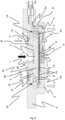
- Figures 9-10 illustrate a particular configuration with the aim to achieve effective and swift closing/opening of the flow control valve 100 in case of penetration of multiphase fluid such as during transition from high viscosity fluid (e.g. oil) 122 to low viscosity fluid (e.g. gas or water) 120.
- a production string 101 is shown within a formation 123, for example the formation of a seabed.
- a fluid reservoir including e.g. gas 120 and oil 122 is located between the surrounding formation 123 and the external of the production string 101.
- the low viscosity - high viscosity fluid interface 121 such as the gas-oil interface is indicated in Figure 9 as a horizontal line.
- the production string 101 comprises a base pipe 102 and a flow control valve 100 establishing a closable opening between the reservoir and the inside of the base pipe 102.
- the flow control device 100 is in Figure 9 shown in a tilted position relative to the fluid interface 121, and in a position on the base pipe 102 that corresponds to a height being in level with the fluid interface 121.
- the fluid interface 121 is approximately located in the middle of the primary flow path inlet 1.
- the position of each fluid control device 100 in a base pipe 102 is random.
- the compartment forming part of the secondary flow path 7, and set up by the secondary fluid flow bushing 19 and the inlet filter 14, contains an interior multi inlet channel 3a having at least two inlets 25 being diagonal, or near diagonal two each other relative to the fluid flow inlet 1.
- the flow control device 100 would, as a result of the mutually diagonal arrangement of the two spaced apart inlets 25, be producing primarily low viscosity fluid such as gas or water 120 into the upper inlet 25.
- the invention is not limited to specific material or a specific geometry.
- any choice of material and/or geometry is possible as long as one of the restrictors creates a mainly laminar flow and the other restrictor creates a mainly turbulent flow during operation.
- directional words such as beneath, radial and axial are used with reference to the drawings, in should be understood that these words are used only for clarity and should not be interpreted as limiting the directional position of the inventive control device.
- All of the embodiments of the inventive flow control device described above are autonomous in the sense that they move (to close or open a fluid inlet) based on a changing property (e.g. viscosity ⁇ ) of the fluid F .
- the coiled pipe 3, the orifice 4, the internal dimensions of the housing 8 and the internally arranged bushings 18,19 may be designed to suit various applications.
- Figure 11A is a principal drawing of the inventive autonomous flow control device 100 configured for stopping low viscosity fluids such as gas and water from entering the desired flow phase of high viscosity fluids such as oil, and where the various forces F 1 , F 2 , F 3 , set up by the fluid flows are indicated, together with the corresponding pressures P 1 , P 2 , P 3 and cross-sectional areas A 1 , A 2 , A 3 .
- Figure 11B shows the measured net force ⁇ F 1-3 acting on the movable piston 9 (vertical axis) as a function of pressure drop ( p 3 - p 1 ) across the flow control device 100 (horizontal axis).
- the values of the net force and the pressure drop is given in Newtons and bars, respectively.
- the net force represents the sum of the forces ⁇ F 1-3 on the piston 9 that opens the flow control device 100 when ⁇ F 1-3 is positive and closes the flow control device 100 when ⁇ F 1-3 is negative.
- Figure 11B shows that, while the fluid control device 100 is open when subjected to oil (high viscosity fluid), it closes almost instantaneously when subjected to gas and water (low viscosity fluid).
- ⁇ F 1-3 is based on the measurements of the pressure drop ( p 3 -p 1 ) in the laminar flow element 3 and the turbulent flow element 4 respectively, both arranged within the secondary flow path 7.
- Figure 11C shows the laminar and turbulent pressure drop ratio ⁇ P laminar / ⁇ P turbulent for a given fluid (vertical axis) as a function of the pressure drops given in Figure 11B (horizontal axis). Based on ⁇ F 1-3 it can be calculated that the flow control device 100 opens when: P 1 ⁇ A 1 + P 3 ⁇ A 3 ⁇ P 2 ⁇ A 2 > 0
- fluid flow restrictors 3,4 may be arranged and configured differently.
- the fluid flow restrictors 3,4 may be reversed in the flow path if the device is intended to be used in a gas reservoir and it is desirable to prevent higher viscosity fluid such as water from entering the production.
- inventive flow control device 100 may be arranged and configured to control and prevent the inflow of other fluids, such as CO 2 (which has been injected into the reservoir) and steam (injected in connection with e.g. so-called Steam-Assisted Gravity Drainage (SAGD) of heavy oil), and water in gas-producing wells.
- other fluids such as CO 2 (which has been injected into the reservoir) and steam (injected in connection with e.g. so-called Steam-Assisted Gravity Drainage (SAGD) of heavy oil), and water in gas-producing wells.
- SAGD Steam-Assisted Gravity Drainage
Landscapes
- Engineering & Computer Science (AREA)
- Life Sciences & Earth Sciences (AREA)
- Mining & Mineral Resources (AREA)
- Geology (AREA)
- Physics & Mathematics (AREA)
- Fluid Mechanics (AREA)
- General Engineering & Computer Science (AREA)
- Geochemistry & Mineralogy (AREA)
- Environmental & Geological Engineering (AREA)
- General Life Sciences & Earth Sciences (AREA)
- Mechanical Engineering (AREA)
- Automation & Control Theory (AREA)
- General Physics & Mathematics (AREA)
- Flow Control (AREA)
- Lift Valve (AREA)
- Multiple-Way Valves (AREA)
- Paper (AREA)
- Electrical Discharge Machining, Electrochemical Machining, And Combined Machining (AREA)
Claims (15)
- Fluidstrom-Steuerungsvorrichtung (100) zum Herstellen einer steuerbaren FluidVerbindung zwischen einem externen Fluidspeicher (120 - 122) und einem Basisrohr (102) einer Fördersteigleitung (101), die umfasst:- einen primären Strömungsweg (2), der im Inneren eines Gehäuses (8) der Fluid-Steuerungsvorrichtung angeordnet ist, wobei der primäre Strömungsweg (2) umfasst:einen Einlass (1) des primären Strömungsweges, der so ausgeführt ist, dass er in Betrieb einen primären Fluidstrom (Fo) aus dem externen Fluidspeicher (120- 122) axial in das Gehäuse (8) der Fluid-Steuerungsvorrichtung hinein leitet, wobei die axiale und eine radiale Richtung als die Richtung senkrecht bzw. parallel zu der Längsrichtung des Basisrohrs (102) definiert sind, sowieeinen Auslass (5) des primären Strömungsweges, der so ausgeführt ist, dass er in Betrieb den primären Fluidstrom (Fo) in das Basisrohr (102) hinein leitet,- einen sekundären Strömungsweg (7), der einen ersten Fluidstrom-Begrenzer (3), der so ausgeführt ist, dass er eine Druckabnahme von einem Druck p1 stromauf von dem ersten Fluidstrom-Begrenzer (3) auf einen Druck p2 stromab von dem ersten Fluidstrom-Begrenzer (3) bewirkt, einen zweiten Fluidstrom-Begrenzer (4), der stromab von dem ersten Fluidstrom-Begrenzer (3) angeordnet und so ausgeführt ist, dass er eine Druckabnahme von dem Druck p2 stromauf von dem zweiten Fluidstrom-Begrenzer (4) auf einen Druck p3 stromab von dem zweiten Fluidstrom-Begrenzer (4) bewirkt, sowie eine Kammer (8) umfasst, die stromab von dem ersten Fluidstrom-Begrenzer (3) und stromauf von dem zweiten Fluidstrom-Begrenzer (4) angeordnet ist, sowie- ein bewegliches Ventilelement (9), das im Inneren des Gehäuses (8) der Fluid-Steuerungsvorrichtung angeordnet und so ausgeführt ist, dass es den primären Strömungsweg (2) für Fluidstrom schließt, wenn es einer Druckkraft aus dem Inneren der Kammer (B) ausgesetzt ist, die eine Schwellen-Druckkraft übersteigt, wobei das bewegliche Ventilelement (9) ein elastisches Element (10) umfasst, das eine herrschende elastische Kraft auf das bewegliche Ventilelement (9) gewährleistet, die von dem Einlass (1) des primären Strömungsweges weg gerichtet ist,dadurch gekennzeichnet, dassder sekundäre Strömungsweg (7) einen Einlass (11) des sekundären Strömungsweges umfasst, der im Inneren eines Gehäuses (8) der Fluid-Steuerungsvorrichtung angeordnet ist und an seinem Eintritt in das Gehäuse (8) der Fluid-Steuerungsvorrichtung einen radialen Versatz zu dem primären Strömungsweg (2) aufweist, undwobei der Einlass (11) des sekundären Strömungsweges des Weiteren so ausgeführt ist, dass er einen sekundären Fluidstrom (f) von dem Fluidspeicher (120-122) so in den sekundären Strömungsweg (7) des Gehäuses (8) der Fluid-Steuerungsvorrichtung hinein leitet,dass in Betrieb der Fluidstrom (F)in den primären Fluidstrom (F0 ), der über den ersten Fluidweg (2) in das Gehäuse (8) der Fluid-Steuerungsvorrichtung eintritt, undin den sekundären Fluidstrom (f) unterteilt wird, der über den sekundären Fluidweg (7) in das Gehäuse (8) der Fluid-Steuerungsvorrichtung eintritt.
- Fluidstrom-Steuerungsvorrichtung (100) nach Anspruch 1, dadurch gekennzeichnet, dass der Einlass (11) des sekundären Strömungsweges so ausgerichtet ist, dass der sekundäre Fluidstrom (f) in Betrieb axial in das Gehäuse (8) der Fluid-Steuerungsvorrichtung einströmt.
- Fluidstrom-Steuerungsvorrichtung (100) nach Anspruch 1 oder 2, dadurch gekennzeichnet, dass die Fluidstrom-Steuerungsvorrichtung (100) des Weiteren umfasst:- eine Einlassbuchse (16), die axial im Inneren des Gehäuses (8) der Fluid-Steuerungsvorrichtung angeordnet ist, um den primären Fluidstrom (Fo) hindurchzuleiten, sowie- eine erste ringförmige Scheibe (19), die axial unterhalb des Einlasses (11) des sekundären Strömungsweges (11) angeordnet ist und deren Öffnung um die Einlassbuchse (1, 16) herum zentriert ist,wobei die erste ringförmige Scheibe (19) umfasst:- eine axial gerichtete erste Arretier-Kante (19a) entlang des Umfangs der inneren Mittelöffnung der ersten ringförmigen Scheibe (19).
- Fluidstrom-Steuerungsvorrichtung (100) nach Anspruch 3, dadurch gekennzeichnet, dass die erste ringförmige Scheibe (19) des Weiteren umfasst:- eine axial gerichtete zweite Arretier-Kante (19b) entlang des Außenumfangs der ersten ringförmigen Scheibe (19), die wenigstens eine Öffnung (19c) aufweist, die so ausgeführt ist, dass sie den sekundären Fluidstrom (f) leitet, der in Betrieb über den Einlass (11) des sekundären Strömungsweges in den Fluidstrom-Begrenzer (3, 4) hinein strömt.
- Fluidstrom-Steuerungsvorrichtung (100) nach einem der vorangehenden Ansprüche, dadurch gekennzeichnet, dass die Fluidstrom-Steuerungsvorrichtung (100) des Weiteren umfasst:- einen Filter (14), der über den Einlass (11) des sekundären Strömungsweges angeordnet ist, um zu verhindern, dass Feststoffteilchen innerhalb des Fluidstroms (F) in den sekundären Strömungsweg (7) eintreten, und gleichzeitig zuzulassen, dass der primäre Fluidstrom (Fo) in Betrieb ungefiltert über den Einlass (1) des primären Strömungsweges strömt.
- Fluidstrom-Steuerungsvorrichtung (100) nach einem der vorangehenden Ansprüche, dadurch gekennzeichnet, dassder erste oder der zweite Durchflussbegrenzer (3, 4) ein Rohr einer Länge L und eines über die Länge L gemittelten mittleren hydraulischen Durchmessers <DL > umfasst,wobei die Länge (L) und der mittlere hydraulische Durchmesser (<DL>) so gewählt werden, dass eine laminare Durchflusskennlinie beim Ausströmen über den ersten und den zweiten Fluidstrom-Begrenzer (3, 4) erzielt wird.
- Fluidstrom-Steuerungsvorrichtung (100) nach einem der Ansprüche 1 - 5, dadurch gekennzeichnet, dassder erste oder der zweite Durchflussbegrenzer (3, 4) ein Rohr einer Länge L und eines über die Länge L gemessenen mittleren hydraulischen Durchmessers <DL > umfasst,wobei die Länge (L) und der mittlere hydraulische Durchmesser (<DL >) so gewählt werden, dass ein Verhältnis zwischen der Länge L und dem mittleren hydraulischen Durchmesser <DL > erzielt wird, das dazu führt, dass die Reynolds-Zahl des Fluidstroms (RE) 4000 oder weniger beträgt, wobei die Reynolds-Zahl definiert ist als
 Q der Volumenstrom Q (m3/s) ist,<AL> die mittlere benetzte Querschnittsfläche über die Länge L (m/s) ist,<DL> der mittlere hydraulische Durchmesser über die Länge L (m) ist,ρ die Dichte des Förderstroms (kg/m3) ist, undµ die dynamische Viskosität der Flüssigkeit (kg/m·s) ist.
 - Fluidstrom-Steuerungsvorrichtung (100) nach einem der vorangehenden Ansprüche, dadurch gekennzeichnet, dass der erste Fluidstrom-Begrenzer (100) umfasst:- einen inneren Auslasskanal (13), der sich im Inneren des Gehäuses (8) der Fluid-Steuerungsvorrichtung befindet und in Fluidverbindung mit dem Einlass (11) des sekundären Strömungsweges steht,- ein äußeres Rohr (3b, 3c) einer Länge L ∗, das sich außerhalb des Gehäuses (8) der Fluid-Steuerungsvorrichtung befindet und in Fluidverbindung mit dem inneren Auslasskanal (13) steht, sowie- einen inneren Rückführkanal (21), der sich im Inneren des Gehäuses (8) der Fluid-Steuerungsvorrichtung befindet und in Fluidverbindung mit dem äußeren Rohr (3b, 3c) steht, wobei ein Teilabschnitt (3d) des äußeren Rohrs (3b, 3c) gewendelt ist.
- Fluidstrom-Steuerungsvorrichtung (100) nach einem der vorangehenden Ansprüche, dadurch gekennzeichnet, dassder sekundäre Strömungsweg (7) einen Auslass (12) des sekundären Strömungsweges umfasst, und dadurch, dasssich mehr als 70 % der Länge des sekundären Strömungsweges (7) zwischen dem Einlass (11) des sekundären Strömungsweges und dem Auslass (1) des sekundären Strömungsweges außerhalb des Gehäuses (8) der Fluid-Steuerungsvorrichtung befinden.
- Fluidstrom-Steuerungsvorrichtung (100) nach einem der vorangehenden Ansprüche, dadurch gekennzeichnet, dass das bewegliche Ventilelement (9) umfasst:- eine untere Scheibe (9a) mit einer Scheiben-Fläche, die der Kammer B zugewandt ist, sowie- eine obere Scheibe (9b), die so angeordnet ist, dass eine Scheiben-Fläche auf der unteren Scheibe (9a) liegt und die andere Scheiben-Fläche dem Einlass (1) des primären Strömungsweges zugewandt ist,wobei der Scheiben-Durchmesser der oberen Scheibe (9b) kleiner ist als der Scheiben-Durchmesser der unteren Scheibe (9b) undder axiale Übergang zwischen der unteren Scheibe (9a) und der oberen Scheibe (9b) stufenlos ist.
- Fluidstrom-Steuerungsvorrichtung (100) nach einem der vorangehenden Ansprüche, dadurch gekennzeichnet, dass die Fluidstrom-Steuerungsvorrichtung (100) des Weiteren umfasst:- eine zweite ringförmige Scheibe (18), die so angeordnet ist, dass ihre Öffnung um den Außenumfang des beweglichen Ventilelementes (9) herum zentriert ist, wobei die zweite ringförmige Scheibe (18) umfasst:- eine axial gerichtete Kante (18a), die sich an dem Außenumfang der zweiten ringförmigen Scheibe (18) entlang erstreckt und so ausgeführt ist, dass sie einen festen axialen Abstand zwischen der sich radial erstreckenden Fläche der zweiten ringförmigen Scheibe (18), die dem Einlass (1) des primären Strömungsweges zugewandt ist, und einer Innenwand des Gehäuses (8) der Fluid-Steuerungsvorrichtung schafft, wobei die axial gerichtete Kante (18a) wenigstens eine Öffnung (18b) aufweist, die so ausgeführt ist, dass sie den primären Fluidstrom (Fo), der über den Einlass (1) des primären Strömungsweges strömt, von dem beweglichen Ventilelement (9) auf den Auslass (5) des primären Strömungsweges zu leitet.
- Fluidstrom-Steuerungsvorrichtung (100) nach einem der vorangehenden Ansprüche, dadurch gekennzeichnet, dass der erste Fluidstrom-Begrenzer (3) ein Rohr (3a) mit mehreren Einlässen umfasst, das wenigstens zwei radial beabstandete Einlässe (25) aufweist, die in Fluidverbindung mit dem sekundären Fluidstrom (f) stehen, der über den Einlass (11) des sekundären Strömungsweges strömt.
- Fluidstrom-Steuerungsvorrichtung (100) nach einem der vorangehenden Ansprüche, dadurch gekennzeichnet, dass der erste Fluidstrom-Begrenzer (3) umfasst:- ein Rohr (3a) mit mehreren Einlässen, das wenigstens zwei Einlässe (25) aufweist, die diagonal oder nahezu diagonal um den Einlass (1) des primären Strömungsweges herum angeordnet sind und in Fluidverbindung mit dem sekundären Fluidstrom (f) stehen, der über den Einlass (11) des sekundären Strömungsweges strömt,- einen inneren Auslasskanal (13), der im Inneren des Gehäuses (8) der Fluid-Steuerungsvorrichtung angeordnet ist und in Fluidverbindung mit dem Rohr (3a) mit mehreren Einlässen steht,- ein äußeres Rohr (3b, 3c) einer Länge L*, das wenigstens teilweise außerhalb des Gehäuses (8) der Fluid-Steuerungsvorrichtung angeordnet ist und in Fluidverbindung mit dem inneren Auslasskanal (13) steht, sowie- einen inneren Rückführkanal (21), der sich im Inneren des Gehäuses (8) der Fluid-Steuerungsvorrichtung befindet und in Fluidverbindung mit dem äußeren Rohr (3b, 3c) steht.
- Fördersteigleitung für Transport von Kohlenwasserstoffen, wobei die Fördersteigleitung umfasst:- ein Basisrohr (102),- eine Verkleidung (104, 107, 108), die an der Außenwand des Basisrohrs (102) angeordnet ist und wenigstens eine Verkleidungs-Eingangsöffnung (111) aufweist, sowie- eine Fluidstrom-Steuerungsvorrichtung (100) nach einem der Ansprüche 1 - 13,wobei die Fluidstrom-Steuerungsvorrichtung (100) in einem Durchgangsloch der Wand des Basisrohrs (102) innerhalb der Verkleidung (104, 107, 108) so angeordnet ist, dass eine steuerbare Fluidverbindung zwischen der Verkleidung (104, 107, 108) und dem Innenraum des Basisrohrs (102) hergestellt wird, unddie Verkleidung (104, 107, 108) so ausgeführt ist, dass sie eine Eingangskammer (109) schafft, die die wenigstens eine Verkleidungs-Eingangsöffnung (111) der Verkleidung (104, 108, 108) abdeckt und den Einlass (1) des primären Strömungsweges sowie den Einlass (11) des sekundären Strömungsweges der Fluidstrom-Steuerungsvorrichtung (100) abdeckt.
- Verfahren zum Steuern von Fluidstrom (F) auf Basis von Änderungen von Fluideigenschaften unter Verwendung einer Fluidstrom-Steuerungsvorrichtung (100) nach einem der Ansprüche 1 - 13, wobei das Verfahren die folgenden Schritte umfasst:- Leiten des primären Fluidstroms (F0 ) , der einen größeren Teil des Fluidstroms (F) bildet, über den primären Strömungsweg (2) im Inneren des Gehäuses (8) der Fluid-Steuerungsvorrichtung; sowie- Leiten des sekundären Fluidstroms (f) über den sekundären Strömungsweg (7), wobei der sekundäre Fluidstrom (f) einen kleineren Teil des Fluidstroms (F) bildet, wenn sich die Fluidstrom-Steuerungsvorrichtung (100) in einer offenen Position befindet, und sich ein größerer Teil der Länge des sekundären Strömungsweges (7) außerhalb des Gehäuses (8) der Fluid-Steuerungsvorrichtung erstreckt.
Priority Applications (3)
| Application Number | Priority Date | Filing Date | Title |
|---|---|---|---|
| EP24207803.8A EP4471530B1 (de) | 2018-03-12 | 2019-03-11 | Flusssteuerungsvorrichtung und -verfahren |
| EP23160343.2A EP4215718B1 (de) | 2018-03-12 | 2019-03-11 | Flusssteuerungsvorrichtung und -verfahren |
| EP24207806.1A EP4471531A3 (de) | 2018-03-12 | 2019-03-11 | Flusssteuerungsvorrichtung und -verfahren |
Applications Claiming Priority (2)
| Application Number | Priority Date | Filing Date | Title |
|---|---|---|---|
| EP18161256.5A EP3540177B1 (de) | 2018-03-12 | 2018-03-12 | Flusssteuerungsvorrichtung und -verfahren |
| PCT/EP2019/055959 WO2019175078A1 (en) | 2018-03-12 | 2019-03-11 | A flow control device and method |
Related Child Applications (4)
| Application Number | Title | Priority Date | Filing Date |
|---|---|---|---|
| EP23160343.2A Division EP4215718B1 (de) | 2018-03-12 | 2019-03-11 | Flusssteuerungsvorrichtung und -verfahren |
| EP23160343.2A Division-Into EP4215718B1 (de) | 2018-03-12 | 2019-03-11 | Flusssteuerungsvorrichtung und -verfahren |
| EP24207803.8A Division EP4471530B1 (de) | 2018-03-12 | 2019-03-11 | Flusssteuerungsvorrichtung und -verfahren |
| EP24207806.1A Division EP4471531A3 (de) | 2018-03-12 | 2019-03-11 | Flusssteuerungsvorrichtung und -verfahren |
Publications (2)
| Publication Number | Publication Date |
|---|---|
| EP3765707A1 EP3765707A1 (de) | 2021-01-20 |
| EP3765707B1 true EP3765707B1 (de) | 2023-04-12 |
Family
ID=61626986
Family Applications (5)
| Application Number | Title | Priority Date | Filing Date |
|---|---|---|---|
| EP18161256.5A Active EP3540177B1 (de) | 2018-03-12 | 2018-03-12 | Flusssteuerungsvorrichtung und -verfahren |
| EP23160343.2A Active EP4215718B1 (de) | 2018-03-12 | 2019-03-11 | Flusssteuerungsvorrichtung und -verfahren |
| EP24207806.1A Pending EP4471531A3 (de) | 2018-03-12 | 2019-03-11 | Flusssteuerungsvorrichtung und -verfahren |
| EP24207803.8A Active EP4471530B1 (de) | 2018-03-12 | 2019-03-11 | Flusssteuerungsvorrichtung und -verfahren |
| EP19711050.5A Active EP3765707B1 (de) | 2018-03-12 | 2019-03-11 | Flusssteuerungsvorrichtung und -verfahren |
Family Applications Before (4)
| Application Number | Title | Priority Date | Filing Date |
|---|---|---|---|
| EP18161256.5A Active EP3540177B1 (de) | 2018-03-12 | 2018-03-12 | Flusssteuerungsvorrichtung und -verfahren |
| EP23160343.2A Active EP4215718B1 (de) | 2018-03-12 | 2019-03-11 | Flusssteuerungsvorrichtung und -verfahren |
| EP24207806.1A Pending EP4471531A3 (de) | 2018-03-12 | 2019-03-11 | Flusssteuerungsvorrichtung und -verfahren |
| EP24207803.8A Active EP4471530B1 (de) | 2018-03-12 | 2019-03-11 | Flusssteuerungsvorrichtung und -verfahren |
Country Status (13)
| Country | Link |
|---|---|
| US (2) | US12398616B2 (de) |
| EP (5) | EP3540177B1 (de) |
| CN (1) | CN111954747B (de) |
| AU (1) | AU2019236379B2 (de) |
| CA (1) | CA3093325A1 (de) |
| DK (2) | DK3540177T3 (de) |
| EA (1) | EA202091981A1 (de) |
| EC (1) | ECSP20063643A (de) |
| ES (2) | ES2885072T3 (de) |
| IL (1) | IL277223A (de) |
| MX (1) | MX2020009542A (de) |
| MY (1) | MY202771A (de) |
| WO (1) | WO2019175078A1 (de) |
Families Citing this family (9)
| Publication number | Priority date | Publication date | Assignee | Title |
|---|---|---|---|---|
| WO2022038188A1 (en) * | 2020-08-19 | 2022-02-24 | Mincon International Limited | Flapper valve for percussion drill tools |
| US11319782B2 (en) * | 2020-09-17 | 2022-05-03 | Baker Hughes Oilfield Operations Llc | Modular screen for a resource exploration and recovery tubular |
| NO348901B1 (en) * | 2020-11-17 | 2025-07-14 | Inflowcontrol As | A flow control device and method |
| CN113062711B (zh) * | 2021-04-07 | 2022-04-22 | 西南石油大学 | 一种多流道旋流自动控液装置 |
| EP4384688B1 (de) * | 2021-08-11 | 2025-11-26 | Swellfix UK Limited | Flusssteuerungsvorrichtung |
| RU208553U1 (ru) * | 2021-10-14 | 2021-12-23 | Общество с ограниченной ответственностью «НАУЧНО ПРОИЗВОДСТВЕННАЯ КОМПАНИЯ «ФИЛЬТР» | Клапан контроля притока |
| RU208554U1 (ru) * | 2021-10-14 | 2021-12-23 | Общество с ограниченной ответственностью «НАУЧНО ПРОИЗВОДСТВЕННАЯ КОМПАНИЯ «ФИЛЬТР» | Клапан контроля притока |
| CN115306356B (zh) * | 2022-08-04 | 2024-01-30 | 中国科学院武汉岩土力学研究所 | 一种提高非均质储层co2封存强度的抽注流量调控装置 |
| US12352131B2 (en) * | 2023-09-08 | 2025-07-08 | Halliburton Energy Services, Inc. | Restrictor and bridge valve for restricting water and producing gas |
Citations (26)
| Publication number | Priority date | Publication date | Assignee | Title |
|---|---|---|---|---|
| US3809111A (en) | 1970-07-10 | 1974-05-07 | A Olsson | Pressure reduction valve |
| US5435393A (en) | 1992-09-18 | 1995-07-25 | Norsk Hydro A.S. | Procedure and production pipe for production of oil or gas from an oil or gas reservoir |
| WO2007126496A2 (en) | 2006-04-03 | 2007-11-08 | Exxonmobil Upstream Research Company | Wellbore method and apparatus for sand and inflow control during well operations |
| WO2008004875A1 (en) | 2006-07-07 | 2008-01-10 | Norsk Hydro Asa | Method for flow control and autonomous valve or flow control device |
| US20080041582A1 (en) | 2006-08-21 | 2008-02-21 | Geirmund Saetre | Apparatus for controlling the inflow of production fluids from a subterranean well |
| US20080041580A1 (en) | 2006-08-21 | 2008-02-21 | Rune Freyer | Autonomous inflow restrictors for use in a subterranean well |
| US20090283275A1 (en) | 2008-05-13 | 2009-11-19 | Baker Hughes Incorporated | Flow Control Device Utilizing a Reactive Media |
| US7819196B2 (en) | 2004-02-20 | 2010-10-26 | Norsk Hydro Asa | Method for operating actuator and an actuator device for use in drainage pipe used for producing oil and/or gas |
| US7823645B2 (en) | 2004-07-30 | 2010-11-02 | Baker Hughes Incorporated | Downhole inflow control device with shut-off feature |
| US7857050B2 (en) | 2006-05-26 | 2010-12-28 | Schlumberger Technology Corporation | Flow control using a tortuous path |
| US20110067878A1 (en) | 2008-05-07 | 2011-03-24 | Bernt Sigve Aadnoy | Flow controller device |
| US7918275B2 (en) | 2007-11-27 | 2011-04-05 | Baker Hughes Incorporated | Water sensitive adaptive inflow control using couette flow to actuate a valve |
| US20110198097A1 (en) | 2010-02-12 | 2011-08-18 | Schlumberger Technology Corporation | Autonomous inflow control device and methods for using same |
| US20110308806A9 (en) | 2009-08-18 | 2011-12-22 | Dykstra Jason D | Method and apparatus for autonomous downhole fluid selection with pathway dependent resistance system |
| WO2013028335A2 (en) | 2011-08-25 | 2013-02-28 | Halliburton Energy Services, Inc. | Downhole fluid flow control system having a fluidic module with a bridge network and method for use of same |
| WO2013139601A2 (en) | 2012-03-21 | 2013-09-26 | Inflowcontrol As | A flow control device and method |
| EP2669466A2 (de) | 2012-05-31 | 2013-12-04 | Weatherford/Lamb Inc. | Einströmungssteuerungsvorrichtung mit extern konfigurierbaren Strömungsöffnungen |
| US20140332229A1 (en) | 2012-10-24 | 2014-11-13 | Halliburton Energy Services, Inc. | Interventionless Adjustable Flow Control Device Using Inflatables |
| US20150021019A1 (en) | 2013-07-19 | 2015-01-22 | Halliburton Energy Services, Inc. | Downhole Fluid Flow Control System and Method Having Autonomous Closure |
| US20150034323A1 (en) | 2013-07-31 | 2015-02-05 | Schlumber Technology Corporation | Sand control system and methodology |
| US20150060084A1 (en) | 2013-08-29 | 2015-03-05 | Schlumberger Technology Corporation | Autonomous flow control system and methodology |
| WO2016033459A1 (en) | 2014-08-29 | 2016-03-03 | Schlumberger Canada Limited | Autonomous flow control system and methodology |
| US9556706B1 (en) | 2015-09-30 | 2017-01-31 | Floway, Inc. | Downhole fluid flow control system and method having fluid property dependent autonomous flow control |
| US9683426B2 (en) | 2012-12-31 | 2017-06-20 | Halliburton Energy Services, Inc. | Distributed inflow control device |
| WO2018142118A1 (en) | 2017-01-31 | 2018-08-09 | Swellfix Uk Limited | Downhole flow control device and method |
| US20190055823A1 (en) | 2017-08-18 | 2019-02-21 | Baker Hughes, A Ge Company, Llc | Flow characteristic control using tube inflow control device |
Family Cites Families (1)
| Publication number | Priority date | Publication date | Assignee | Title |
|---|---|---|---|---|
| US10060221B1 (en) * | 2017-12-27 | 2018-08-28 | Floway, Inc. | Differential pressure switch operated downhole fluid flow control system |
-
2018
- 2018-03-12 DK DK18161256.5T patent/DK3540177T3/da active
- 2018-03-12 EP EP18161256.5A patent/EP3540177B1/de active Active
- 2018-03-12 ES ES18161256T patent/ES2885072T3/es active Active
-
2019
- 2019-03-11 DK DK19711050.5T patent/DK3765707T3/da active
- 2019-03-11 EP EP23160343.2A patent/EP4215718B1/de active Active
- 2019-03-11 EP EP24207806.1A patent/EP4471531A3/de active Pending
- 2019-03-11 EA EA202091981A patent/EA202091981A1/ru unknown
- 2019-03-11 CN CN201980024432.7A patent/CN111954747B/zh active Active
- 2019-03-11 ES ES19711050T patent/ES2949787T3/es active Active
- 2019-03-11 US US16/979,189 patent/US12398616B2/en active Active
- 2019-03-11 EP EP24207803.8A patent/EP4471530B1/de active Active
- 2019-03-11 AU AU2019236379A patent/AU2019236379B2/en active Active
- 2019-03-11 MY MYPI2020004633A patent/MY202771A/en unknown
- 2019-03-11 EP EP19711050.5A patent/EP3765707B1/de active Active
- 2019-03-11 CA CA3093325A patent/CA3093325A1/en active Pending
- 2019-03-11 WO PCT/EP2019/055959 patent/WO2019175078A1/en not_active Ceased
- 2019-03-11 MX MX2020009542A patent/MX2020009542A/es unknown
-
2020
- 2020-09-08 IL IL277223A patent/IL277223A/en unknown
- 2020-10-08 EC ECSENADI202063643A patent/ECSP20063643A/es unknown
-
2023
- 2023-11-24 US US18/518,639 patent/US20240084670A1/en active Pending
Patent Citations (26)
| Publication number | Priority date | Publication date | Assignee | Title |
|---|---|---|---|---|
| US3809111A (en) | 1970-07-10 | 1974-05-07 | A Olsson | Pressure reduction valve |
| US5435393A (en) | 1992-09-18 | 1995-07-25 | Norsk Hydro A.S. | Procedure and production pipe for production of oil or gas from an oil or gas reservoir |
| US7819196B2 (en) | 2004-02-20 | 2010-10-26 | Norsk Hydro Asa | Method for operating actuator and an actuator device for use in drainage pipe used for producing oil and/or gas |
| US7823645B2 (en) | 2004-07-30 | 2010-11-02 | Baker Hughes Incorporated | Downhole inflow control device with shut-off feature |
| WO2007126496A2 (en) | 2006-04-03 | 2007-11-08 | Exxonmobil Upstream Research Company | Wellbore method and apparatus for sand and inflow control during well operations |
| US7857050B2 (en) | 2006-05-26 | 2010-12-28 | Schlumberger Technology Corporation | Flow control using a tortuous path |
| WO2008004875A1 (en) | 2006-07-07 | 2008-01-10 | Norsk Hydro Asa | Method for flow control and autonomous valve or flow control device |
| US20080041580A1 (en) | 2006-08-21 | 2008-02-21 | Rune Freyer | Autonomous inflow restrictors for use in a subterranean well |
| US20080041582A1 (en) | 2006-08-21 | 2008-02-21 | Geirmund Saetre | Apparatus for controlling the inflow of production fluids from a subterranean well |
| US7918275B2 (en) | 2007-11-27 | 2011-04-05 | Baker Hughes Incorporated | Water sensitive adaptive inflow control using couette flow to actuate a valve |
| US20110067878A1 (en) | 2008-05-07 | 2011-03-24 | Bernt Sigve Aadnoy | Flow controller device |
| US20090283275A1 (en) | 2008-05-13 | 2009-11-19 | Baker Hughes Incorporated | Flow Control Device Utilizing a Reactive Media |
| US20110308806A9 (en) | 2009-08-18 | 2011-12-22 | Dykstra Jason D | Method and apparatus for autonomous downhole fluid selection with pathway dependent resistance system |
| US20110198097A1 (en) | 2010-02-12 | 2011-08-18 | Schlumberger Technology Corporation | Autonomous inflow control device and methods for using same |
| WO2013028335A2 (en) | 2011-08-25 | 2013-02-28 | Halliburton Energy Services, Inc. | Downhole fluid flow control system having a fluidic module with a bridge network and method for use of same |
| WO2013139601A2 (en) | 2012-03-21 | 2013-09-26 | Inflowcontrol As | A flow control device and method |
| EP2669466A2 (de) | 2012-05-31 | 2013-12-04 | Weatherford/Lamb Inc. | Einströmungssteuerungsvorrichtung mit extern konfigurierbaren Strömungsöffnungen |
| US20140332229A1 (en) | 2012-10-24 | 2014-11-13 | Halliburton Energy Services, Inc. | Interventionless Adjustable Flow Control Device Using Inflatables |
| US9683426B2 (en) | 2012-12-31 | 2017-06-20 | Halliburton Energy Services, Inc. | Distributed inflow control device |
| US20150021019A1 (en) | 2013-07-19 | 2015-01-22 | Halliburton Energy Services, Inc. | Downhole Fluid Flow Control System and Method Having Autonomous Closure |
| US20150034323A1 (en) | 2013-07-31 | 2015-02-05 | Schlumber Technology Corporation | Sand control system and methodology |
| US20150060084A1 (en) | 2013-08-29 | 2015-03-05 | Schlumberger Technology Corporation | Autonomous flow control system and methodology |
| WO2016033459A1 (en) | 2014-08-29 | 2016-03-03 | Schlumberger Canada Limited | Autonomous flow control system and methodology |
| US9556706B1 (en) | 2015-09-30 | 2017-01-31 | Floway, Inc. | Downhole fluid flow control system and method having fluid property dependent autonomous flow control |
| WO2018142118A1 (en) | 2017-01-31 | 2018-08-09 | Swellfix Uk Limited | Downhole flow control device and method |
| US20190055823A1 (en) | 2017-08-18 | 2019-02-21 | Baker Hughes, A Ge Company, Llc | Flow characteristic control using tube inflow control device |
Non-Patent Citations (6)
| Title |
|---|
| FAISAL TURKI MANEE AL-KHELAIW: "A comprehensive approach to the design of advanced well completions", THESIS, 1 March 2013 (2013-03-01), pages 1 - 225, XP093156543 |
| HAAVARD AAKRE: "Autonomous Inflow Control Valve for Heavy and Extra-Heavy Oil", SPE-171141-MS, 24 September 2014 (2014-09-24), pages 1 - 13, XP093156516, DOI: 10.2118/171141-MS |
| IGOR JOVANOV: "Faculty of Science and Technology", MASTER THESIS, 1 September 2016 (2016-09-01), pages 1 - 82, XP093156520 |
| MIGUEL ARMENTA: "Applications of Mechanical External Casing Packers", SPE 105380, 11 March 2007 (2007-03-11), pages 1 - 6, XP093156550, DOI: 10.2118/105380-MS |
| VIDAR MATHIESEN: "The Autonomous RCP Valve - New Technology for Inflow Control In Horizontal Wells", SPE 145737, 6 September 2011 (2011-09-06), pages 1 - 10, XP093156557, DOI: 10.2118/145737-MS |
| YUNUS A. QENGEL , JOHN M. CIMBALA , ROBERT H. TURNER: "Fundamentals of thermal-fluid science fourth edition in SI units", 1 January 2012, THE MCGRAW-HILL COMPANIES, INC, article ANONYMOUS: "Passage ; Fundamentals of thermal-fluid science fourth edition in SI units", pages: 540 - 540, XP093156539 |
Also Published As
| Publication number | Publication date |
|---|---|
| EP4215718A1 (de) | 2023-07-26 |
| CN111954747B (zh) | 2022-09-30 |
| US20200408066A1 (en) | 2020-12-31 |
| EA202091981A1 (ru) | 2021-02-25 |
| WO2019175078A1 (en) | 2019-09-19 |
| ES2949787T3 (es) | 2023-10-03 |
| MY202771A (en) | 2024-05-21 |
| EP4471530C0 (de) | 2025-11-05 |
| EP4471531A3 (de) | 2025-01-22 |
| EP4471530A3 (de) | 2025-01-22 |
| CN111954747A (zh) | 2020-11-17 |
| EP4471530B1 (de) | 2025-11-05 |
| EP4215718B1 (de) | 2025-02-26 |
| EP3765707A1 (de) | 2021-01-20 |
| US20240084670A1 (en) | 2024-03-14 |
| ES2885072T3 (es) | 2021-12-13 |
| AU2019236379A1 (en) | 2020-10-08 |
| CA3093325A1 (en) | 2019-09-19 |
| EP4215718C0 (de) | 2025-02-26 |
| BR112020018432A2 (pt) | 2020-12-29 |
| MX2020009542A (es) | 2020-10-05 |
| US12398616B2 (en) | 2025-08-26 |
| DK3540177T3 (da) | 2021-08-30 |
| DK3765707T3 (da) | 2023-07-10 |
| ECSP20063643A (es) | 2021-01-29 |
| AU2019236379B2 (en) | 2021-12-23 |
| EP4471531A2 (de) | 2024-12-04 |
| EP3540177A1 (de) | 2019-09-18 |
| EP4471530A2 (de) | 2024-12-04 |
| IL277223A (en) | 2020-10-29 |
| EP3540177B1 (de) | 2021-08-04 |
Similar Documents
| Publication | Publication Date | Title |
|---|---|---|
| EP3765707B1 (de) | Flusssteuerungsvorrichtung und -verfahren | |
| US20230243238A1 (en) | Fluid Control System | |
| US12353228B2 (en) | Flow control device and method | |
| EP3194714B1 (de) | Autonomes durchflussregelsystem und methodologie | |
| HK40014434B (en) | A flow control device and method | |
| HK40014434A (en) | A flow control device and method | |
| OA21601A (en) | A Flow Control Device And Method. | |
| EA042421B1 (ru) | Регулятор потока и соответствующий способ | |
| BR112020018432B1 (pt) | Dispositivo de controle de fluxo, coluna de produção para transporte de hidrocarbonetos e método de controle de fluxo de fluido |
Legal Events
| Date | Code | Title | Description |
|---|---|---|---|
| STAA | Information on the status of an ep patent application or granted ep patent |
Free format text: STATUS: UNKNOWN |
|
| STAA | Information on the status of an ep patent application or granted ep patent |
Free format text: STATUS: THE INTERNATIONAL PUBLICATION HAS BEEN MADE |
|
| PUAI | Public reference made under article 153(3) epc to a published international application that has entered the european phase |
Free format text: ORIGINAL CODE: 0009012 |
|
| STAA | Information on the status of an ep patent application or granted ep patent |
Free format text: STATUS: REQUEST FOR EXAMINATION WAS MADE |
|
| 17P | Request for examination filed |
Effective date: 20201007 |
|
| AK | Designated contracting states |
Kind code of ref document: A1 Designated state(s): AL AT BE BG CH CY CZ DE DK EE ES FI FR GB GR HR HU IE IS IT LI LT LU LV MC MK MT NL NO PL PT RO RS SE SI SK SM TR |
|
| AX | Request for extension of the european patent |
Extension state: BA ME |
|
| DAV | Request for validation of the european patent (deleted) | ||
| DAX | Request for extension of the european patent (deleted) | ||
| STAA | Information on the status of an ep patent application or granted ep patent |
Free format text: STATUS: EXAMINATION IS IN PROGRESS |
|
| 17Q | First examination report despatched |
Effective date: 20211001 |
|
| REG | Reference to a national code |
Ref country code: DE Ref legal event code: R079 Ref document number: 602019027452 Country of ref document: DE Free format text: PREVIOUS MAIN CLASS: E21B0034080000 Ipc: E21B0007040000 |
|
| GRAP | Despatch of communication of intention to grant a patent |
Free format text: ORIGINAL CODE: EPIDOSNIGR1 |
|
| STAA | Information on the status of an ep patent application or granted ep patent |
Free format text: STATUS: GRANT OF PATENT IS INTENDED |
|
| RIC1 | Information provided on ipc code assigned before grant |
Ipc: G05D 7/01 20060101ALI20221006BHEP Ipc: E21B 43/12 20060101ALI20221006BHEP Ipc: E21B 34/08 20060101ALI20221006BHEP Ipc: E21B 7/04 20060101AFI20221006BHEP |
|
| INTG | Intention to grant announced |
Effective date: 20221021 |
|
| GRAS | Grant fee paid |
Free format text: ORIGINAL CODE: EPIDOSNIGR3 |
|
| GRAA | (expected) grant |
Free format text: ORIGINAL CODE: 0009210 |
|
| STAA | Information on the status of an ep patent application or granted ep patent |
Free format text: STATUS: THE PATENT HAS BEEN GRANTED |
|
| AK | Designated contracting states |
Kind code of ref document: B1 Designated state(s): AL AT BE BG CH CY CZ DE DK EE ES FI FR GB GR HR HU IE IS IT LI LT LU LV MC MK MT NL NO PL PT RO RS SE SI SK SM TR |
|
| REG | Reference to a national code |
Ref country code: GB Ref legal event code: FG4D |
|
| REG | Reference to a national code |
Ref country code: CH Ref legal event code: EP |
|
| REG | Reference to a national code |
Ref country code: DE Ref legal event code: R096 Ref document number: 602019027452 Country of ref document: DE |
|
| REG | Reference to a national code |
Ref country code: IE Ref legal event code: FG4D |
|
| REG | Reference to a national code |
Ref country code: AT Ref legal event code: REF Ref document number: 1559877 Country of ref document: AT Kind code of ref document: T Effective date: 20230515 |
|
| P01 | Opt-out of the competence of the unified patent court (upc) registered |
Effective date: 20230524 |
|
| REG | Reference to a national code |
Ref country code: DK Ref legal event code: T3 Effective date: 20230708 |
|
| REG | Reference to a national code |
Ref country code: RO Ref legal event code: EPE |
|
| REG | Reference to a national code |
Ref country code: NL Ref legal event code: FP |
|
| REG | Reference to a national code |
Ref country code: LT Ref legal event code: MG9D |
|
| REG | Reference to a national code |
Ref country code: NO Ref legal event code: T2 Effective date: 20230412 |
|
| REG | Reference to a national code |
Ref country code: ES Ref legal event code: FG2A Ref document number: 2949787 Country of ref document: ES Kind code of ref document: T3 Effective date: 20231003 |
|
| PG25 | Lapsed in a contracting state [announced via postgrant information from national office to epo] |
Ref country code: SE Free format text: LAPSE BECAUSE OF FAILURE TO SUBMIT A TRANSLATION OF THE DESCRIPTION OR TO PAY THE FEE WITHIN THE PRESCRIBED TIME-LIMIT Effective date: 20230412 Ref country code: PT Free format text: LAPSE BECAUSE OF FAILURE TO SUBMIT A TRANSLATION OF THE DESCRIPTION OR TO PAY THE FEE WITHIN THE PRESCRIBED TIME-LIMIT Effective date: 20230814 |
|
| PG25 | Lapsed in a contracting state [announced via postgrant information from national office to epo] |
Ref country code: RS Free format text: LAPSE BECAUSE OF FAILURE TO SUBMIT A TRANSLATION OF THE DESCRIPTION OR TO PAY THE FEE WITHIN THE PRESCRIBED TIME-LIMIT Effective date: 20230412 Ref country code: PL Free format text: LAPSE BECAUSE OF FAILURE TO SUBMIT A TRANSLATION OF THE DESCRIPTION OR TO PAY THE FEE WITHIN THE PRESCRIBED TIME-LIMIT Effective date: 20230412 Ref country code: LV Free format text: LAPSE BECAUSE OF FAILURE TO SUBMIT A TRANSLATION OF THE DESCRIPTION OR TO PAY THE FEE WITHIN THE PRESCRIBED TIME-LIMIT Effective date: 20230412 Ref country code: LT Free format text: LAPSE BECAUSE OF FAILURE TO SUBMIT A TRANSLATION OF THE DESCRIPTION OR TO PAY THE FEE WITHIN THE PRESCRIBED TIME-LIMIT Effective date: 20230412 Ref country code: IS Free format text: LAPSE BECAUSE OF FAILURE TO SUBMIT A TRANSLATION OF THE DESCRIPTION OR TO PAY THE FEE WITHIN THE PRESCRIBED TIME-LIMIT Effective date: 20230812 Ref country code: HR Free format text: LAPSE BECAUSE OF FAILURE TO SUBMIT A TRANSLATION OF THE DESCRIPTION OR TO PAY THE FEE WITHIN THE PRESCRIBED TIME-LIMIT Effective date: 20230412 Ref country code: GR Free format text: LAPSE BECAUSE OF FAILURE TO SUBMIT A TRANSLATION OF THE DESCRIPTION OR TO PAY THE FEE WITHIN THE PRESCRIBED TIME-LIMIT Effective date: 20230713 |
|
| PG25 | Lapsed in a contracting state [announced via postgrant information from national office to epo] |
Ref country code: FI Free format text: LAPSE BECAUSE OF FAILURE TO SUBMIT A TRANSLATION OF THE DESCRIPTION OR TO PAY THE FEE WITHIN THE PRESCRIBED TIME-LIMIT Effective date: 20230412 |
|
| REG | Reference to a national code |
Ref country code: DE Ref legal event code: R026 Ref document number: 602019027452 Country of ref document: DE |
|
| PG25 | Lapsed in a contracting state [announced via postgrant information from national office to epo] |
Ref country code: SK Free format text: LAPSE BECAUSE OF FAILURE TO SUBMIT A TRANSLATION OF THE DESCRIPTION OR TO PAY THE FEE WITHIN THE PRESCRIBED TIME-LIMIT Effective date: 20230412 |
|
| PLBI | Opposition filed |
Free format text: ORIGINAL CODE: 0009260 |
|
| PLAX | Notice of opposition and request to file observation + time limit sent |
Free format text: ORIGINAL CODE: EPIDOSNOBS2 |
|
| PG25 | Lapsed in a contracting state [announced via postgrant information from national office to epo] |
Ref country code: SM Free format text: LAPSE BECAUSE OF FAILURE TO SUBMIT A TRANSLATION OF THE DESCRIPTION OR TO PAY THE FEE WITHIN THE PRESCRIBED TIME-LIMIT Effective date: 20230412 Ref country code: SK Free format text: LAPSE BECAUSE OF FAILURE TO SUBMIT A TRANSLATION OF THE DESCRIPTION OR TO PAY THE FEE WITHIN THE PRESCRIBED TIME-LIMIT Effective date: 20230412 Ref country code: EE Free format text: LAPSE BECAUSE OF FAILURE TO SUBMIT A TRANSLATION OF THE DESCRIPTION OR TO PAY THE FEE WITHIN THE PRESCRIBED TIME-LIMIT Effective date: 20230412 Ref country code: CZ Free format text: LAPSE BECAUSE OF FAILURE TO SUBMIT A TRANSLATION OF THE DESCRIPTION OR TO PAY THE FEE WITHIN THE PRESCRIBED TIME-LIMIT Effective date: 20230412 |
|
| REG | Reference to a national code |
Ref country code: AT Ref legal event code: UEP Ref document number: 1559877 Country of ref document: AT Kind code of ref document: T Effective date: 20230412 |
|
| 26 | Opposition filed |
Opponent name: TENDEKA LIMITED Effective date: 20240112 |
|
| PG25 | Lapsed in a contracting state [announced via postgrant information from national office to epo] |
Ref country code: SI Free format text: LAPSE BECAUSE OF FAILURE TO SUBMIT A TRANSLATION OF THE DESCRIPTION OR TO PAY THE FEE WITHIN THE PRESCRIBED TIME-LIMIT Effective date: 20230412 |
|
| PLBB | Reply of patent proprietor to notice(s) of opposition received |
Free format text: ORIGINAL CODE: EPIDOSNOBS3 |
|
| PG25 | Lapsed in a contracting state [announced via postgrant information from national office to epo] |
Ref country code: SI Free format text: LAPSE BECAUSE OF FAILURE TO SUBMIT A TRANSLATION OF THE DESCRIPTION OR TO PAY THE FEE WITHIN THE PRESCRIBED TIME-LIMIT Effective date: 20230412 |
|
| REG | Reference to a national code |
Ref country code: CH Ref legal event code: PL |
|
| PG25 | Lapsed in a contracting state [announced via postgrant information from national office to epo] |
Ref country code: BG Free format text: LAPSE BECAUSE OF FAILURE TO SUBMIT A TRANSLATION OF THE DESCRIPTION OR TO PAY THE FEE WITHIN THE PRESCRIBED TIME-LIMIT Effective date: 20230412 |
|
| PG25 | Lapsed in a contracting state [announced via postgrant information from national office to epo] |
Ref country code: LU Free format text: LAPSE BECAUSE OF NON-PAYMENT OF DUE FEES Effective date: 20240311 |
|
| PG25 | Lapsed in a contracting state [announced via postgrant information from national office to epo] |
Ref country code: MC Free format text: LAPSE BECAUSE OF FAILURE TO SUBMIT A TRANSLATION OF THE DESCRIPTION OR TO PAY THE FEE WITHIN THE PRESCRIBED TIME-LIMIT Effective date: 20230412 |
|
| PG25 | Lapsed in a contracting state [announced via postgrant information from national office to epo] |
Ref country code: MC Free format text: LAPSE BECAUSE OF FAILURE TO SUBMIT A TRANSLATION OF THE DESCRIPTION OR TO PAY THE FEE WITHIN THE PRESCRIBED TIME-LIMIT Effective date: 20230412 Ref country code: LU Free format text: LAPSE BECAUSE OF NON-PAYMENT OF DUE FEES Effective date: 20240311 Ref country code: BG Free format text: LAPSE BECAUSE OF FAILURE TO SUBMIT A TRANSLATION OF THE DESCRIPTION OR TO PAY THE FEE WITHIN THE PRESCRIBED TIME-LIMIT Effective date: 20230412 |
|
| REG | Reference to a national code |
Ref country code: BE Ref legal event code: MM Effective date: 20240331 |
|
| PG25 | Lapsed in a contracting state [announced via postgrant information from national office to epo] |
Ref country code: BE Free format text: LAPSE BECAUSE OF NON-PAYMENT OF DUE FEES Effective date: 20240331 |
|
| PG25 | Lapsed in a contracting state [announced via postgrant information from national office to epo] |
Ref country code: IE Free format text: LAPSE BECAUSE OF NON-PAYMENT OF DUE FEES Effective date: 20240311 |
|
| PG25 | Lapsed in a contracting state [announced via postgrant information from national office to epo] |
Ref country code: IE Free format text: LAPSE BECAUSE OF NON-PAYMENT OF DUE FEES Effective date: 20240311 Ref country code: BE Free format text: LAPSE BECAUSE OF NON-PAYMENT OF DUE FEES Effective date: 20240331 Ref country code: CH Free format text: LAPSE BECAUSE OF NON-PAYMENT OF DUE FEES Effective date: 20240331 |
|
| PGFP | Annual fee paid to national office [announced via postgrant information from national office to epo] |
Ref country code: NL Payment date: 20250214 Year of fee payment: 7 |
|
| PGFP | Annual fee paid to national office [announced via postgrant information from national office to epo] |
Ref country code: DE Payment date: 20250312 Year of fee payment: 7 |
|
| PGFP | Annual fee paid to national office [announced via postgrant information from national office to epo] |
Ref country code: DK Payment date: 20250214 Year of fee payment: 7 Ref country code: RO Payment date: 20250127 Year of fee payment: 7 |
|
| PGFP | Annual fee paid to national office [announced via postgrant information from national office to epo] |
Ref country code: NO Payment date: 20250115 Year of fee payment: 7 |
|
| PGFP | Annual fee paid to national office [announced via postgrant information from national office to epo] |
Ref country code: AT Payment date: 20250207 Year of fee payment: 7 |
|
| PGFP | Annual fee paid to national office [announced via postgrant information from national office to epo] |
Ref country code: FR Payment date: 20250217 Year of fee payment: 7 |
|
| PGFP | Annual fee paid to national office [announced via postgrant information from national office to epo] |
Ref country code: IT Payment date: 20250123 Year of fee payment: 7 Ref country code: GB Payment date: 20250310 Year of fee payment: 7 |
|
| PGFP | Annual fee paid to national office [announced via postgrant information from national office to epo] |
Ref country code: ES Payment date: 20250409 Year of fee payment: 7 |
|
| APAH | Appeal reference modified |
Free format text: ORIGINAL CODE: EPIDOSCREFNO |
|
| APBP | Date of receipt of notice of appeal recorded |
Free format text: ORIGINAL CODE: EPIDOSNNOA2O |
|
| APBM | Appeal reference recorded |
Free format text: ORIGINAL CODE: EPIDOSNREFNO |
|
| APBP | Date of receipt of notice of appeal recorded |
Free format text: ORIGINAL CODE: EPIDOSNNOA2O |
|
| PLAB | Opposition data, opponent's data or that of the opponent's representative modified |
Free format text: ORIGINAL CODE: 0009299OPPO |
|
| PG25 | Lapsed in a contracting state [announced via postgrant information from national office to epo] |
Ref country code: CY Free format text: LAPSE BECAUSE OF FAILURE TO SUBMIT A TRANSLATION OF THE DESCRIPTION OR TO PAY THE FEE WITHIN THE PRESCRIBED TIME-LIMIT; INVALID AB INITIO Effective date: 20190311 |
|
| R26 | Opposition filed (corrected) |
Opponent name: TENDEKA LIMITED Effective date: 20240112 |
|
| PG25 | Lapsed in a contracting state [announced via postgrant information from national office to epo] |
Ref country code: HU Free format text: LAPSE BECAUSE OF FAILURE TO SUBMIT A TRANSLATION OF THE DESCRIPTION OR TO PAY THE FEE WITHIN THE PRESCRIBED TIME-LIMIT; INVALID AB INITIO Effective date: 20190311 |
|
| APBQ | Date of receipt of statement of grounds of appeal recorded |
Free format text: ORIGINAL CODE: EPIDOSNNOA3O |
|
| APBQ | Date of receipt of statement of grounds of appeal recorded |
Free format text: ORIGINAL CODE: EPIDOSNNOA3O |
|
| APAH | Appeal reference modified |
Free format text: ORIGINAL CODE: EPIDOSCREFNO |
|
| PG25 | Lapsed in a contracting state [announced via postgrant information from national office to epo] |
Ref country code: TR Free format text: LAPSE BECAUSE OF FAILURE TO SUBMIT A TRANSLATION OF THE DESCRIPTION OR TO PAY THE FEE WITHIN THE PRESCRIBED TIME-LIMIT Effective date: 20230412 |