EP3765669B1 - Covering for a machine for producing a fibrous material web - Google Patents
Covering for a machine for producing a fibrous material web Download PDFInfo
- Publication number
- EP3765669B1 EP3765669B1 EP19710395.5A EP19710395A EP3765669B1 EP 3765669 B1 EP3765669 B1 EP 3765669B1 EP 19710395 A EP19710395 A EP 19710395A EP 3765669 B1 EP3765669 B1 EP 3765669B1
- Authority
- EP
- European Patent Office
- Prior art keywords
- threads
- seam
- fabrics according
- flat
- covering
- Prior art date
- Legal status (The legal status is an assumption and is not a legal conclusion. Google has not performed a legal analysis and makes no representation as to the accuracy of the status listed.)
- Active
Links
- 239000002657 fibrous material Substances 0.000 title 1
- 239000004744 fabric Substances 0.000 claims description 39
- 238000005304 joining Methods 0.000 claims description 14
- 239000000835 fiber Substances 0.000 claims description 13
- 230000035699 permeability Effects 0.000 claims description 12
- 238000003466 welding Methods 0.000 claims description 11
- 230000005540 biological transmission Effects 0.000 claims description 8
- 229920001971 elastomer Polymers 0.000 claims description 4
- 239000000806 elastomer Substances 0.000 claims description 4
- XLYOFNOQVPJJNP-UHFFFAOYSA-N water Substances O XLYOFNOQVPJJNP-UHFFFAOYSA-N 0.000 claims description 4
- 229920002635 polyurethane Polymers 0.000 claims description 2
- 239000004814 polyurethane Substances 0.000 claims description 2
- 230000000694 effects Effects 0.000 description 8
- 238000000034 method Methods 0.000 description 8
- 230000008901 benefit Effects 0.000 description 6
- 238000004519 manufacturing process Methods 0.000 description 6
- 238000009941 weaving Methods 0.000 description 6
- 238000012545 processing Methods 0.000 description 5
- 230000008569 process Effects 0.000 description 4
- 230000006378 damage Effects 0.000 description 3
- 239000004952 Polyamide Substances 0.000 description 2
- 230000002745 absorbent Effects 0.000 description 2
- 239000002250 absorbent Substances 0.000 description 2
- 239000000853 adhesive Substances 0.000 description 2
- 230000001070 adhesive effect Effects 0.000 description 2
- 230000008859 change Effects 0.000 description 2
- 238000010276 construction Methods 0.000 description 2
- 238000013461 design Methods 0.000 description 2
- 239000000463 material Substances 0.000 description 2
- 229920002647 polyamide Polymers 0.000 description 2
- 230000000717 retained effect Effects 0.000 description 2
- 238000002604 ultrasonography Methods 0.000 description 2
- 238000013459 approach Methods 0.000 description 1
- 229920002678 cellulose Polymers 0.000 description 1
- 239000001913 cellulose Substances 0.000 description 1
- 230000007547 defect Effects 0.000 description 1
- 230000001419 dependent effect Effects 0.000 description 1
- 239000006260 foam Substances 0.000 description 1
- 238000003780 insertion Methods 0.000 description 1
- 230000037431 insertion Effects 0.000 description 1
- 239000007788 liquid Substances 0.000 description 1
- 238000005259 measurement Methods 0.000 description 1
- 239000012528 membrane Substances 0.000 description 1
- 229920000642 polymer Polymers 0.000 description 1
- 239000002861 polymer material Substances 0.000 description 1
- 239000011347 resin Substances 0.000 description 1
- 229920005989 resin Polymers 0.000 description 1
- 238000009958 sewing Methods 0.000 description 1
- 238000012360 testing method Methods 0.000 description 1
Images


Classifications
-
- D—TEXTILES; PAPER
- D21—PAPER-MAKING; PRODUCTION OF CELLULOSE
- D21F—PAPER-MAKING MACHINES; METHODS OF PRODUCING PAPER THEREON
- D21F7/00—Other details of machines for making continuous webs of paper
- D21F7/08—Felts
- D21F7/083—Multi-layer felts
-
- D—TEXTILES; PAPER
- D21—PAPER-MAKING; PRODUCTION OF CELLULOSE
- D21F—PAPER-MAKING MACHINES; METHODS OF PRODUCING PAPER THEREON
- D21F7/00—Other details of machines for making continuous webs of paper
- D21F7/08—Felts
- D21F7/10—Seams thereof
-
- D—TEXTILES; PAPER
- D21—PAPER-MAKING; PRODUCTION OF CELLULOSE
- D21F—PAPER-MAKING MACHINES; METHODS OF PRODUCING PAPER THEREON
- D21F1/00—Wet end of machines for making continuous webs of paper
- D21F1/0027—Screen-cloths
- D21F1/0036—Multi-layer screen-cloths
-
- D—TEXTILES; PAPER
- D21—PAPER-MAKING; PRODUCTION OF CELLULOSE
- D21F—PAPER-MAKING MACHINES; METHODS OF PRODUCING PAPER THEREON
- D21F1/00—Wet end of machines for making continuous webs of paper
- D21F1/0027—Screen-cloths
- D21F1/0054—Seams thereof
Definitions
- the invention relates to a covering, in particular seam felt for a machine for producing a fibrous web according to the preamble of claim 1.
- Clothing used in paper machines usually consists of endless belt loops. These belt loops are continuously guided in a circle over a large number of support and guide elements during machine operation and are always under tension. They are also subjected to stresses from presses, suction elements and the like.
- the EP0 425 523 the use of flat-woven panels. These are provided in twice the length of the required covering. By folding the long ends and placing them on top of each other, a two-layer laminate structure is created. By removing CD threads at the folds, seam loops are created. By interlocking the seam loops of both front ends and inserting a plug-in element, this basic structure can be made endless. In contrast to the round-woven structures, the warp threads of the fabric are the MD threads of the covering. In this way, seam coverings can be very efficiently.
- a flat fabric can be produced in advance and stored as a roll if the dimensions of the finished covering are not yet known. To produce the covering, only the required length must be unwound from the roll and, if necessary, shortened to the width of the covering.
- these are in the area of the seam.
- the properties at the seam differ from those of the rest of the covering. For example, the permeability to water and air is often higher here than in the rest of the covering. This can lead to a loss of quality due to markings in the paper.
- MD threads are threads that are oriented in the longitudinal direction of the basic structure or the covering, or deviate from this by a maximum of 10°. (MD - machine direction)
- CD threads are threads that are oriented in the cross direction of the basic structure or the covering, or deviate from this by a maximum of 10° (CD-cross direction).
- the diameter of the thread is understood to be the diameter of the circle that has the same area as the cross-section of the thread, or as the sum of the cross-sections of the individual monofilaments.
- the largest circle that can be completely inserted into the seam loop is determined.
- the diameter of this circle is then considered to be the diameter of the seam loop.
- a covering in particular a seam felt for a machine for producing a fibrous web, in particular a paper, cardboard, tissue or cellulose web, is proposed.
- the covering comprises a base structure which comprises or consists of a two-layer laminate structure made of one or more flat-woven elements.
- the laminate structure has MD threads that form seam loops at the two front ends of the basic structure and through which the two layers of the laminate structure are connected to each other.
- the covering is made endless by connecting its front ends with a seam. This seam is made by the Interlocking of the seam loops of both front ends and the insertion of a plug-in element.
- the diameter of the seam loops (LD loop diameter) and the diameter of the associated MD threads (MDYD-MD yarn diameter) have a ratio LD/MDYD between 2.5 and 4, in particular between 2.7 and 3.6.
- closing the seam is very easy.
- the seam of a seam covering is usually closed in the paper machine itself by pulling in a pintle or pintle wire. This pulling in is done manually and can be a lengthy process, especially on wide machines.
- the fact that the loop diameter is not too small in relation to the MD thread diameter makes pulling in the pintle wire easier. In addition to this ergonomic advantage, the time required to pull in a new covering is reduced, which offers economic advantages for the operator of the system.
- the diameter or the LD/MDYD ratio must not be too large. Loops that are too large can lead to mechanical markings in the paper, as the bends of the loop, for example when passing through a press nip, are imprinted on the paper. On the other hand, large loops also mean that the seam area itself becomes comparatively large. Since this seam area is structurally different from the rest of the fabric and in particular has a different permeability for water and/or air, there is a risk of hydraulic markings in the paper in the seam area due to different drainage. For this reason, it is desirable to keep the seam area as small as possible.
- the LD/MDYD range according to the invention between 2.5 and 4, in particular between 2.7 and 3.6, has proven to be the optimal compromise here.
- the characterising value to be used is not the absolute loop diameter (in mm), but the relative value LD/MDYD.
- the basic structure comprises further components in addition to the two-layer laminate structure.
- another fabric layer and/or a scrim layer and/or a fleece layer can be provided.
- the additional components can be arranged on the outside of the two-layer laminate structure.
- an additional component can also be arranged between the two layers of the two-layer laminate structure.
- the two layers of the two-layer laminate structure can be made from a single flat-woven element.
- This flat fabric is - at least approximately - twice the length of the subsequent covering.
- By folding and laying the two ends of the flat fabric on the middle part of the flat fabric a double-layer structure is created, with the seam loops forming at the folds.
- the long ends of the flat-woven element can be arranged in a so-called "join" area, butt-joined, overlapping or spaced apart.
- the overlap or the spacing is advantageously less than 5 cm, in particular less than 2 cm.
- the two layers can be made up of several flat-woven elements. All flat-woven elements can have the same length. However, it can also be provided that these flat-woven elements have different lengths. In these designs, too, the seam loops are formed by folding over one or two flat-woven elements. In this way, Here too, the two layers of the laminate structure are connected to each other by the seam loops.
- the elements can differ in one or more features.
- the features can be the weave pattern, the material, the diameter or structure of the MD or CD threads or other characteristics of the fabric that are known to the person skilled in the art.
- One or all of the flat-woven elements can be made as plain weave, for example. This type of fabric is very simple and quick to produce, which is economically advantageous.
- one or all of the flat-woven elements have floats that extend over two or more threads. This can reduce the strength of the moiré effect. Nevertheless, the advantage of easy creation of the seam loops is retained.
- plug-in elements known from the state of the art can be used as plug-in elements.
- plug-in wires made of one or more filaments can be used.
- the two layers of the two-layer laminate structure can advantageously be joined together by sewing or other suitable techniques.
- such connections can be provided near the seam loops and/or near the join areas.
- each of the flat-woven elements has a first and a second longitudinal end
- the two-layer laminate structure has at least one joint at which two longitudinal ends are connected to one another.
- at least one of the join regions is designed as a joint.
- the joined longitudinal ends can belong to the same flat-woven element or to different flat-woven elements, as described above.
- connection at the joint(s) can be made using a variety of known methods.
- the connection at at least one joint can be made using an adhesive connection and/or a welded connection.
- welded joints using ultrasound or a laser are possible.
- Welding using an NIR laser in the transmission welding process is particularly advantageous.
- Laser transmission welding is particularly advantageous because the usual polyamide yarns of the fabric are transparent to laser light in a wide frequency range and can be welded very easily using absorbent, e.g. black, connecting threads.
- Such woven seams are used, for example, to make woven forming fabrics endless. Although woven seams are often more complex to produce than adhesive or welded joints, such a joint can have a very high level of strength.
- Connecting the long ends with a joint offers a number of advantages. Firstly, the tensile strength of the two-layer laminate structure is increased.
- the joint also serves to better fix the loose ends of the MD threads at the long ends. Without such a fixation, In some applications, these ends can come loose during operation of the covering and be transported through any fleece layers etc. to the surface of the covering. There, these loose ends can cause damage and markings in the produced fibrous web. By fixing the loose ends through the joint, working out these ends can be completely or largely avoided.
- the extent of the at least one joint in the machine direction (MD) is less than 15 mm, less than 10 mm, in particular less than 5 mm. Since there is also a risk of different drainage conditions at the join or joint points compared to the rest of the covering, a small extent of these areas is advantageous for reducing the tendency to mark.
- this embodiment of the invention takes a different approach. It is accepted that in the joining area the properties of the basic structure or the covering may differ from the rest of the covering. Instead, the aim is to keep this different area in the MD direction as small as possible. Particularly in the case of felts, where the applied fleece layers act as a type of diffuser, the different drainage in this very small area can no longer be perceived as a marking in the paper.
- the at least one joint in particular all joints, are realized by connecting elements, in particular connecting threads, which are welded to at least one, preferably both longitudinal ends.
- connecting threads can be used as connecting elements, which are arranged in the CD direction of the covering, whereby for a joint a maximum of three connecting threads, in particular a maximum of two connecting threads, are provided.
- one or more of the connecting threads are interwoven with MD threads of at least one longitudinal end.
- Laser transmission welding is very suitable for this, for example, because the usual polyamide yarns of the fabric are transparent to laser light in a wide frequency range - especially between 800 nm and 1000 nm - and can be welded very easily using absorbent, e.g. black connecting threads.
- the transparent joining partner essentially only heats up on the surface during this joining process.
- the structure of this transparent joining partner is largely retained. This is advantageous, for example, if the transparent joining partner is an MD thread which is subject to tensile stress in the finished covering. This is not significantly weakened by laser transmission welding.
- Such a joint also has sufficient strength to withstand processing steps in the further course of production, in particular needling.
- joints welded using ultrasound are often very brittle and fragile and are at least partially destroyed by needling. Due to the destruction of the joint, individual thread ends or parts of thread can come loose and protrude from the covering, which can create markings or damage the fiber web.
- fasteners instead of threads, other types of fasteners can be used, such as woven or non-woven ribbons, strips of
- connecting elements have only a small expansion in the MD direction, in particular less than 5 mm, less than 2 mm or even better less than 1 mm.
- the MD threads which are used in particular for forming the seam loops are designed as monofilaments, in particular as monofilaments with a round cross-section.
- the diameter of the MD threads is between 0.15mm and 0.7mm, in particular between 0.3mm and 0.5mm.
- the number of seam loops per unit length is first determined.
- the seam loop density of a covering can change during its manufacturing process. For example, thermal processing steps can cause the covering to shrink in the transverse direction. Therefore, the seam loop density is usually lower before the first thermal processing step, usually between 55% and 80%, while it is then higher in the finished covering.
- the seam loop density values given in this application refer to the finished covering, unless otherwise stated.
- the loop density of the seam can be between 64% and 90%, in particular between 72% and 86%, especially between 78% and 82%. Values of 80%, 81%, 82%, 83%, 84% and 85% have proven to be particularly advantageous.
- the permeability of the seam tends to be higher than in the rest of the covering, the permeability of the seam can be reduced by a comparatively high seam loop density.
- an increase in the loop density beyond 90% can lead to the easy seamability of the covering mentioned at the beginning being partially lost, as it becomes more difficult to get the seam loops to interlock.
- the seam loop density range given here is also, in a sense, an optimal range for two opposing requirements.
- the weft threads of flat weaves correspond to the MD threads of the covering, a higher MD thread density and thus also a higher loop density can be achieved when using flat weaves.
- loop densities of more than 64%, in particular more than 72% or 78%, described in this application can either not be achieved at all with circular fabrics, or by means of extreme weaving conditions such as a greatly increased warp tension, which lead to a greatly accelerated wear of the loom.
- this embodiment of the invention it is possible to produce a covering with a seam that has a low permeability due to the high loop density, but is nevertheless easy to close due to the optimal LD/MDYD ratio.
- Other known methods for reducing seam permeability such as inserting a flow-restricting element ("scrim") in the seam area, make closing the seam more difficult.
- scrim flow-restricting element
- the seam area of the covering - after closing the seam by means of the plug-in element - can have a permeability which corresponds to between 80% and 130%, in particular between 90% and 120% of the permeability of the covering in an area remote from the seam.
- the covering has one or more layers of nonwoven fibers at least on its upper side that touches the paper.
- the covering can be a press felt.
- one or more layers of nonwoven fibers can also be provided on the underside of the covering that touches the rollers.
- some of the fleece fibers have a fiber fineness of 67 dtex or more.
- these relatively coarse fibers can be arranged in direct proximity to the basic structure. They are often applied as a coarse fleece layer and needled to the basic structure.
- Nonwoven fibers with a fineness of 44 dtex and less can also be used.
- these comparatively fine fibers can be arranged on the upper side of the covering that touches the paper.
- These fine fibers may be arranged on a nonwoven layer containing the above-mentioned coarse fibres of 67 dtex or more and needled to them.
- the fleece fibers can comprise or consist of an elastomer, in particular a polyurethane.
- an elastomer in particular a polyurethane.
- the covering can expand better again after passing through the press nip.
- the drainage properties of the covering remain at a high level for longer, which offers economic advantages for the operator.
- Fleece fibers made of elastomer are particularly advantageous in the area of the seam and in the join area(s). Their use is also advantageous here because the elastic effect further reduces the tendency for these areas to mark.
- At least one strip-shaped, flow-hindering element is provided, which is designed such that the permeability for air and/or water in the region of the seam is essentially the same as in the rest of the covering.
- This flow-restricting element can be implemented in various ways. For example, it can be formed as a band of woven or non-woven material. Alternatively, it can be a membrane, a film or a polymer foam. The element can also be implemented in the form of a hardened liquid resin. The person skilled in the art will be able to come up with other suitable implementations without any problem.
- Figure 1a shows a single flat-woven element 2 with a first longitudinal end 21 and a second longitudinal end 22 in plan view.
- the points 31 and 32 are the selected folding points 31, 32 from which the seam loops 41, 42 are formed.
- Figure 1b shows the flat-woven element 2 again in a side view.
- One or more CD threads can be removed at the folding points 31, 32.
- the flat-woven element 2 is folded at fold points 31, 32 and the folded parts are placed back on the flat-woven element 2.
- the longitudinal ends 21, 22 can overlap, touch or, as in Figure 1c shown, have a small distance from each other.
- the join 20 can be designed as a joint 200 at which two longitudinal ends 21, 22 are connected to each other.
- An advantageous joining method is welding, in particular ultrasonic and laser transmission welding.
- the two layers of the two-layer laminate structure 1 can be connected to each other at fixing points 110, in particular sewn.
- Figure 2a shows a two-layer laminate structure 1 comprising two flat-woven elements 2, 2a.
- the seam loops 41, 42 are formed here by the MD threads 10 of the first flat-woven element 2.
- the second flat-woven element 2a is arranged such that its first longitudinal end 21a forms a join region with the second longitudinal end 22 of the first flat-woven element 2, while its second longitudinal end 22a forms a join region with the first longitudinal end 21 of the first flat-woven element 2.
- These join regions 20 can again be designed as joints 200.
- the second flat-woven element 2a can be connected, in particular sewn, to the first flat-woven element 2 at fixing points 110.
- Figure 2b shows another embodiment of a two-layer laminate structure 1 comprising two flat-woven elements 2, 2a. It differs from the one shown in Figure 2a shown structure in that a seam loop 41 is formed by MD threads 10 of the first flat-woven element 2, while the second seam loop 42 is formed by MD threads 10 of the second flat-woven element 2a.
- the two flat-woven elements 2, 2a can be the same, in particular the same length. Alternatively, however, it can also be provided that they differ in one or more features, in particular in length.
- the Figure 2c shows a further embodiment of a two-layer laminate structure 1, which comprises three flat-woven elements 2, 2a, 2b.
- Figure 3 shows an embodiment of a covering according to one aspect of the invention.
- Fleece layers 5a, 5b, 5c, 5d are attached on the two-layer laminate structure 1 made of Figure 1c. These are usually attached by needling. The needling also further connects the two layers of the two-layer laminate structure 1 to one another.
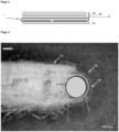
- FIG 4 shows a seam loop 42, formed from an MD thread 10.
- the MD thread 10 is designed here as a round monofilament.
- a fleece layer 15 is provided on the upper side of the covering.
- a circle is inscribed in the seam loop 42. This is the largest circle that can be can be inserted completely into the seam loop 42. The determination of such circles and their diameters is a common geometric exercise. In commercially available microscopes, such a measurement is also included in the range of functions of the operating software.
- the seam loops are also vertical or largely vertical, so that the problem of possible distortion does not arise.
- the diameter of the circle is in the case of Figure 4 1200 ⁇ m.
- the diameter of the MD thread is 340 ⁇ m.
- a covering with such seam loops therefore meets the feature of the characterizing part of claim 1.
- FIG 5 An example of a section of a joint 200 is shown, which is produced by means of laser transmission welding.
- the transparent joining partners 100, 105 are connected to one another here by means of a connecting element 120.
- the connecting element 120 is in Figure 5 exemplified as a black thread 120.
- the transparent joining partners 100, 105 can be, for example, MD threads 10 of longitudinal ends 21, 22 of one or two flat-woven elements 2, 2a, 2b. It can be seen that the connecting element 120 was noticeably deformed by the welding process.
- the transparent joining partners 100, 105 are, however, structurally largely undamaged. Due to this property, connections made by means of laser transmission welding can also be distinguished from other welded connections.
Landscapes
- Paper (AREA)
Description
Die Erfindung betrifft eine Bespannung, insbesondere Nahtfilz für eine Maschine zur Herstellung einer Faserstoffbahn gemäß dem Oberbegriff des Anspruchs 1.The invention relates to a covering, in particular seam felt for a machine for producing a fibrous web according to the preamble of
Bespannungen, die in Papiermaschinen zum Einsatz kommen, bestehen üblicherweise aus endlosen Bandschlaufen. Diese Bandschlaufen werden im Betrieb der Maschine kontinuierlich über eine Vielzahl von Stütz- und Leitelementen im Kreis geführt und stehen dabei stets unter eine Zugspannung. Zudem sind sie Belastungen durch Pressen, Saugelementen und ähnlichem ausgesetzt.Clothing used in paper machines usually consists of endless belt loops. These belt loops are continuously guided in a circle over a large number of support and guide elements during machine operation and are always under tension. They are also subjected to stresses from presses, suction elements and the like.
Um diesen Belastungen dauerhaft standhalten zu können, weisen solche Bespannungen häufig eine gewebte Grundstruktur auf.In order to be able to withstand these loads permanently, such coverings often have a woven basic structure.
Es sind verschiedene Möglichkeiten bekannt, eine gewebte Grundstruktur in der für die Bespannung benötigten Endloskonfiguration herzustellen. Am häufigsten werden solche Strukturen rund-gewebt. Dabei wird direkt auf dem Webstuhl eine schlauchförmige Gewebestruktur erzeugt. Beim Einsatz in einer Papiermaschine wird dieser Schlauch gedreht, so dass sie Schussfäden des Webstuhls zu dem Maschinenrichtungs-Fäden (MD-Fäden) der Bespannung werden.There are various ways of producing a woven base structure in the endless configuration required for the covering. The most common way to do this is to use circular weaving. This creates a tubular fabric structure directly on the loom. When used in a paper machine, this tube is twisted so that the weft threads of the loom become the machine direction threads (MD threads) of the covering.
Diese Art des Webens ist jedoch sehr zeitaufwändig. Zudem muss beim Weben bereits die benötigte Länge der Bespannung exakt bekannt sein. Ein Weben auf Vorrat' ist nicht möglich.However, this type of weaving is very time-consuming. In addition, the required length of the covering must be known exactly when weaving. Weaving in advance is not possible.
Um eine effizientere Art der Herstellung zu ermöglichen, schlägt die
Diese Art der Herstellung bringt jedoch auch Nachteile mit sich.However, this type of production also has disadvantages.
Zum einen liegen diese im Bereich der Naht. An der Nahtstelle unterscheiden sich die Eigenschaften von denen des restlichen Teils der Bespannung. Häufig ist hierbeispielsweise die Permeabilität für Wasser und Luft höher, als im Rest der Bespannung. Dadurch kann es zu einer Qualitätseinbuße durch Markierungen im Papier kommen.Firstly, these are in the area of the seam. The properties at the seam differ from those of the rest of the covering. For example, the permeability to water and air is often higher here than in the rest of the covering. This can lead to a loss of quality due to markings in the paper.
Eine weitere kritische Stelle ist der sogenannte "Join". Durch das Umfalten kommen die beiden längsseitigen Enden auf einer Seite der Grundstruktur zu liegen. Sie können dabei auf Stoß, überlappend oder mit Abstand angeordnet sein. Auch an dieser Stelle unterscheiden sich die Eigenschaften der Grundstruktur vom übrigen Bereich, wodurch Markierungen im Papier entstehen können.Another critical point is the so-called "join". By folding, the two long ends come to lie on one side of the basic structure. They can be arranged butt-to-butt, overlapping or spaced apart. Here too, the properties of the basic structure differ from the rest of the area, which can cause marks in the paper.
Es ist daher die Aufgabe der vorliegenden Erfindung, eine Bespannung anzugeben, die schnell und ökonomisch herstellbar sowie einsetzbar ist, und gleichzeitig die aus dem Stand der Technik bekannten Qualitätsmängel überwindet.It is therefore the object of the present invention to provide a covering which can be produced and used quickly and economically and at the same time overcomes the quality defects known from the prior art.
Diese Aufgabe wird vollständig gelöst durch eine Bespannung nach dem Kennzeichen des Anspruchs 1.This object is completely achieved by a covering according to the characterizing part of
Zum besseren Verständnis der Erfindung seien noch einige Erläuterungen und Definitionen vorangestellt, welche im Rahmen dieser Anwendung verwendet werden.For a better understanding of the invention, some explanations and definitions are given which are used in the context of this application.
Unter MD-Fäden sollen Fäden verstanden werden, die in Längsrichtung der Grundstruktur, bzw. der Bespannung orientiert sind, oder von dieser um maximal 10° abweichen. (MD - machine direction)MD threads are threads that are oriented in the longitudinal direction of the basic structure or the covering, or deviate from this by a maximum of 10°. (MD - machine direction)
Unter CD-Fäden sollen Fäden verstanden sind, die in Querrichtung der Grundstruktur bzw. der Bespannung orientiert sind, oder von dieser um maximal 10° abweichen. (CD-cross direction).CD threads are threads that are oriented in the cross direction of the basic structure or the covering, or deviate from this by a maximum of 10° (CD-cross direction).
Im Rahmen dieser Anmeldung wird der Begriff Durchmesser eines Fadens' verwendet. Bei runden Fäden ist dieser Begriff wohldefiniert.In this application, the term 'diameter of a thread' is used. For round threads, this term is well defined.
Für Monofilamente, die von der runden Form abweichen, oder auch für aus mehreren Monofilamenten gezwirnte Fäden soll unter dem Durchmesser des Fadens der Durchmesser desjenigen Kreises verstanden werden, welcher dieselbe Fläche aufweist, wie der Querschnitt des Fadens, bzw. wie die Summe der Querschnitte der einzelnen Monofilamente.For monofilaments that deviate from the round shape, or for threads twisted from several monofilaments, the diameter of the thread is understood to be the diameter of the circle that has the same area as the cross-section of the thread, or as the sum of the cross-sections of the individual monofilaments.
Für ein Monofilament mit quadratischem Querschnitt und 1 mm Kantenläge ergäbe sich somit der folgende Durchmesser D: 
Zur Bestimmung des Durchmessers einer Nahtschlaufe wird der größte Kreis ermittelt, welcher sich vollständig in die Nahtschlaufe einfügen lässt. Der Durchmesser dieses Kreises wird dann als der Durchmesser der Nahtschlaufe betrachtet.To determine the diameter of a seam loop, the largest circle that can be completely inserted into the seam loop is determined. The diameter of this circle is then considered to be the diameter of the seam loop.
Es wird eine Bespannung, insbesondere ein Nahtfilz für eine Maschine zur Herstellung einer Faserstoffbahn, insbesondere einer Papier-, Karton-, Tissue- oder Zellstoffbahn vorgeschlagen. Die Bespannung umfasst eine Grundstruktur, die eine zweilagige Laminatstruktur aus einem oder mehreren flachgewebte Elemente umfasst oder daraus besteht.A covering, in particular a seam felt for a machine for producing a fibrous web, in particular a paper, cardboard, tissue or cellulose web, is proposed. The covering comprises a base structure which comprises or consists of a two-layer laminate structure made of one or more flat-woven elements.
Dabei weist die Laminatstruktur MD-Fäden auf, welche an den beiden stirnseitigen Enden der Grundstruktur Nahtschlaufen ausbilden und über die die beiden Lagen der Laminatstruktur miteinander verbunden sind. Die Bespannung ist durch Verbinden ihrer stirnseitigen Enden mittels einer Naht endlos gemacht. Diese Naht ist durch das Ineinandergreifen der Nahtschlaufen beider stirnseitiger Enden und das Einführen eines Steckelements gebildet.The laminate structure has MD threads that form seam loops at the two front ends of the basic structure and through which the two layers of the laminate structure are connected to each other. The covering is made endless by connecting its front ends with a seam. This seam is made by the Interlocking of the seam loops of both front ends and the insertion of a plug-in element.
Erfindungsgemäß ist dabei vorgesehen, dass der Durchmesser der Nahtschlaufen (LD-loop diameter) und der Durchmesser der zugehörigen MD-Fäden (MDYD-MD yarn diameter) ein Verhältnis LD/MDYD zwischen 2.5 und 4, insbesondere zwischen 2.7 und 3.6 aufweisen.According to the invention, it is provided that the diameter of the seam loops (LD loop diameter) and the diameter of the associated MD threads (MDYD-MD yarn diameter) have a ratio LD/MDYD between 2.5 and 4, in particular between 2.7 and 3.6.
Versuche der Anmelderin haben ergeben, dass bei den erfindungsgemäßen LD/MDYD-Verhältnissen die entstehende Naht in vielerlei Hinsicht optimal ist.Tests carried out by the applicant have shown that with the LD/MDYD ratios according to the invention, the resulting seam is optimal in many respects.
Zum einen weist sie eine sehr hohe Festigkeit auf, ohne die ein erfolgreicher Einsatz z.B. als Nahtfilz nicht möglich ist.On the one hand, it has a very high strength, without which successful use, e.g. as seam felt, is not possible.
Zudem ist das Schließen der Naht sehr einfach möglich. Die Naht einer Nahtbespannung wird üblicherweise in der Papiermaschine selbst durch Einziehen eines Steckelements, auch Pintle oder Steckdraht genannt, geschlossen. Dieses Einziehen geschieht händisch, und kann besonders bei breiten Maschinen ein langwieriger Prozess sein. Dadurch, dass der Schlaufendurchmesser im Verhältnis zum MD-Faden Durchmesser nicht zu klein wird, wird das Einziehen des Steckdrahtes erleichtert. Zu diesem ergonomischen Vorteil verkürzt sich die Zeit für das Einziehen einer neuen Bespannung, was für den Betreiber der Anlage ökonomische Vorteile bietet.In addition, closing the seam is very easy. The seam of a seam covering is usually closed in the paper machine itself by pulling in a pintle or pintle wire. This pulling in is done manually and can be a lengthy process, especially on wide machines. The fact that the loop diameter is not too small in relation to the MD thread diameter makes pulling in the pintle wire easier. In addition to this ergonomic advantage, the time required to pull in a new covering is reduced, which offers economic advantages for the operator of the system.
Jedoch darf der Durchmesser, bzw. das LD/MDYD Verhältnis auch nicht zu groß werden. Zu große Schlaufen können einerseits zu mechanischen Markierungen im Papier führen, indem sich die Biegungen der Schlaufe z.B. beim Durchlaufen eines Pressnips in das Papier einprägen. Andererseits bedeuten große Schlaufen auch, dass der Nahtbereich selbst vergleichsweise groß wird. Da sich dieser Nahtbereich strukturell vom Rest der Bespannung unterscheidet, und insbesondere auch eine veränderte Permeabilität für Wasser und/oder Luft aufweist, besteht im Nahtbereich die Gefahr von hydraulischen Markierungen im Papier aufgrund einer unterschiedlichen Entwässerung. Aus diesem Grund ist es wünschenswert, den Naht Bereich so klein wie möglich zu halten.However, the diameter or the LD/MDYD ratio must not be too large. Loops that are too large can lead to mechanical markings in the paper, as the bends of the loop, for example when passing through a press nip, are imprinted on the paper. On the other hand, large loops also mean that the seam area itself becomes comparatively large. Since this seam area is structurally different from the rest of the fabric and in particular has a different permeability for water and/or air, there is a risk of hydraulic markings in the paper in the seam area due to different drainage. For this reason, it is desirable to keep the seam area as small as possible.
Der erfindungsgemäße Bereich LD/MDYD zwischen 2.5 und 4, insbesondere zwischen 2.7 und 3.6 hat sich hier als der optimale Kompromiss erwiesen.The LD/MDYD range according to the invention between 2.5 and 4, in particular between 2.7 and 3.6, has proven to be the optimal compromise here.
Insbesondere hat die Anmelderin erkannt, dass als charakterisierende Größe nicht der absolute Schlaufendurchmesser (in mm), sondern der Relativwert LD/MDYD herangezogen werden muss.In particular, the applicant has recognised that the characterising value to be used is not the absolute loop diameter (in mm), but the relative value LD/MDYD.
Vorteilhafte Ausführungen der Erfindung sind in den abhängigen Ansprüchen beschrieben.Advantageous embodiments of the invention are described in the dependent claims.
Es kann vorgesehen sein, dass die Grundstruktur neben der zweilagigen Laminatstruktur noch weitere Komponenten umfasst. So kann z.B. noch eine weitere Gewebelage und/der eine Gelegelage und/oder eine Vlieslage vorgesehen sein. Die zusätzlichen Komponenten können außen auf der zweilagigen Laminatstruktur angeordnet sein. Alternativ oder zusätzlich kann eine zusätzliche Komponente auch zwischen den beiden Lagern der zweilagigen Laminatstruktur angeordnet sein.It can be provided that the basic structure comprises further components in addition to the two-layer laminate structure. For example, another fabric layer and/or a scrim layer and/or a fleece layer can be provided. The additional components can be arranged on the outside of the two-layer laminate structure. Alternatively or additionally, an additional component can also be arranged between the two layers of the two-layer laminate structure.
Die beiden Lagen der zweilagigen Laminatstruktur können aus einem einzigen flachgewebten Element gebildet sein. Dieses Flachgewebe weist - zumindest in etwa -die doppelte Länge der späteren Bespannung auf. Durch Falten und Ablegen der beiden Enden des Flachgewebes auf den Mittelteil des Flachgewebes entsteht eine doppellagige Struktur wobei an sich den Faltstellen die Nahtschlaufen ausbilden. Die längsseitigen Enden des flachgewebten Elementes können dabei in einem sogenannten ,Join`-Bereich auf Stoß, überlappend oder mit Abstand angeordnet sein. Der Überlapp bzw. der Abstand beträgt dabei vorteilhafterweise weniger als 5cm, insbesondere weniger als 2 cm.The two layers of the two-layer laminate structure can be made from a single flat-woven element. This flat fabric is - at least approximately - twice the length of the subsequent covering. By folding and laying the two ends of the flat fabric on the middle part of the flat fabric, a double-layer structure is created, with the seam loops forming at the folds. The long ends of the flat-woven element can be arranged in a so-called "join" area, butt-joined, overlapping or spaced apart. The overlap or the spacing is advantageously less than 5 cm, in particular less than 2 cm.
Alternativ können die beiden Lagen aus mehreren flachgewebten Elementen gebildet sein. Dabei können alle flachgewebten Elemente dieselbe Länge aufweisen. Es kann jedoch auch vorgesehen sein, dass diese flachgewebten Elemente unterschiedliche Längen aufweisen. Auch in diesen Ausführungen sind die Nahtschlaufen durch umschlagen von einem oder zwei flachgewebten Elementen gebildet. Auf diese Weise sind die beiden Lagen der Laminatstruktur auch hier durch die Nahtschlaufen miteinander verbunden.Alternatively, the two layers can be made up of several flat-woven elements. All flat-woven elements can have the same length. However, it can also be provided that these flat-woven elements have different lengths. In these designs, too, the seam loops are formed by folding over one or two flat-woven elements. In this way, Here too, the two layers of the laminate structure are connected to each other by the seam loops.
Umfasst die Grundstruktur mehrere flachgewebte Elemente so entstehen auch mehrere Join-Bereiche, für die dasselbe gilt, wie oben für den Fall eines Join-Bereiches beschrieben.If the basic structure includes several flat-woven elements, several join areas are created, for which the same applies as described above for the case of one join area.
Bei der Verwendung von mehreren flachgewebten Elementen besteht die Möglichkeit, dass alle Elemente aus demselben Gewebe bestehen. Alternativ kann aber auch vorgesehen sein, dass sich die Elemente in einem oder mehreren Merkmalen unterscheiden. Dabei kann es sich bei den Merkmalen um das Webmuster handeln, das Material, den Durchmesser bzw. den Aufbau der MD-, bzw. CD-Fäden oder andere Kennzeichen des Gewebes, die dem Fachmann bekannt sind.When using several flat-woven elements, it is possible for all elements to be made of the same fabric. Alternatively, however, the elements can differ in one or more features. The features can be the weave pattern, the material, the diameter or structure of the MD or CD threads or other characteristics of the fabric that are known to the person skilled in the art.
Eines oder alle der flachgewebten Elemente können beispielsweise als ,plain weave', also mittels einer Leinwandbindung realisiert sein. Diese Art des Gewebes ist sehr einfach und schnell herzustellen, was ökonomisch vorteilhaft ist.One or all of the flat-woven elements can be made as plain weave, for example. This type of fabric is very simple and quick to produce, which is economically advantageous.
Ein bekannter Effekt bei zweilagigen Gewebestrukturen ist jedoch der Moire Effekt. Dieser tritt bei zweilagigen Leinwandgeweben verstärkt auf. Zur Reduzierung dieses Effektes, und damit auch zur Reduzierung der Gefahr von Markierungen im Papier, die durch diesen Effekt ausgelöst werden, kann es vorteilhaft sein, wenn zumindest eines oder alle der flachgewebten Elemente kein Leinwandgewebe sind.However, a well-known effect in two-layer fabric structures is the moiré effect. This occurs more frequently in two-layer plain weave fabrics. To reduce this effect, and thus also to reduce the risk of markings in the paper caused by this effect, it can be advantageous if at least one or all of the flat-woven elements are not plain weave fabrics.
Insbesondere kann es hierfür vorteilhaft sein, wenn eines oder alle der flachgewebten Elemente Flottierungen aufweist, die sich über zwei oder mehrere Fäden erstrecken. Somit kann die Stärke des Moire-Effekts reduziert werden. Trotzdem bleibt der Vorteil der einfachen Erzeugung der Nahtschlaufen erhalten.In particular, it can be advantageous if one or all of the flat-woven elements have floats that extend over two or more threads. This can reduce the strength of the moiré effect. Nevertheless, the advantage of easy creation of the seam loops is retained.
Als Steckelement können alle aus dem Stand der Technik bekannten Steckelemente verwendet werden. Insbesondere können Steckdrähte aus einem oder mehreren Filamenten eingesetzt werden.All plug-in elements known from the state of the art can be used as plug-in elements. In particular, plug-in wires made of one or more filaments can be used.
Die beiden Lagen der zweilagige Laminatstruktur können vorteilhafterweise durch Vernähen oder andere geeignete Techniken miteinander verbunden werden. Bevorzugt können solche Verbindungen in der Nähe der Nahtschlaufen und/oder in der Nähe der Join-Bereiche vorgesehen sein.The two layers of the two-layer laminate structure can advantageously be joined together by sewing or other suitable techniques. Preferably, such connections can be provided near the seam loops and/or near the join areas.
In bevorzugten Ausführungen kann vorgesehen sein, dass jedes der flachgewebten Elemente ein erstes und ein zweites längsseitiges Ende aufweist, und die zweilagige Laminatstruktur zumindest eine Fügestelle aufweist, an der zwei längsseitige Enden miteinander verbunden sind. In dieser Ausführung ist also zumindest einer der Join-Bereiche als Fügestelle ausgeführt. Dabei können die gefügten längsseitigen Enden, wie oben beschrieben zu demselben flachgewebten Element oder zu verschiedenen flachgewebten Elementen gehören können.In preferred embodiments, it can be provided that each of the flat-woven elements has a first and a second longitudinal end, and the two-layer laminate structure has at least one joint at which two longitudinal ends are connected to one another. In this embodiment, at least one of the join regions is designed as a joint. The joined longitudinal ends can belong to the same flat-woven element or to different flat-woven elements, as described above.
Die Verbindung an der bzw. den Fügestellen kann durch eine Vielzahl von bekannten Verfahren erfolgen. Insbesondere kann die Verbindung an der zumindest einen Fügestelle durch eine Klebeverbindung und/oder eine Schweißverbindung realisiert ist. So sind beispielsweise mittels Ultraschall oder mittels eines Lasers geschweißte Fügestellen möglich. Besonders vorteilhaft ist das Verschweißen mittels eines NIR-Lasers im Transmissionsschweißverfahren. Das Lasertransmissionssschweißen ist insbesondere deshalb vorteilhaft, da die üblichen Polyamidgarne des Gewebes für Laserlicht in einem weiten Frequenzbereich transparent sind, und sehr einfach durch unter Verwendung absorbierender, z.B. schwarzer Verbindungsfäden verschweißt werden können. Es ist auch möglich, die Fügestelle in Form einer Webnaht auszuführen. Solche Webnähte werden beispielsweise verwendet, um gewebte Formiersiebe endlos zu machen. Webnähte sind zwar häufig aufwändiger herzustellen, als Klebe- oder Schweißverbindungen, jedoch kann eine derartige Fügestelle eine sehr hohe Festigkeit aufweisen .The connection at the joint(s) can be made using a variety of known methods. In particular, the connection at at least one joint can be made using an adhesive connection and/or a welded connection. For example, welded joints using ultrasound or a laser are possible. Welding using an NIR laser in the transmission welding process is particularly advantageous. Laser transmission welding is particularly advantageous because the usual polyamide yarns of the fabric are transparent to laser light in a wide frequency range and can be welded very easily using absorbent, e.g. black, connecting threads. It is also possible to make the joint in the form of a woven seam. Such woven seams are used, for example, to make woven forming fabrics endless. Although woven seams are often more complex to produce than adhesive or welded joints, such a joint can have a very high level of strength.
Ein Verbinden der längsseitigen Enden durch eine Fügestelle bietet eine Reihe von Vorteilen. Zum einen wird die Zugfestigkeit der zweilagigen Laminatstruktur dadurch erhöht. Die Fügestelle dient zudem auch dazu, die losen Enden der MD Fäden an den längsseitigen Enden besser zu fixieren. Ohne eine solche Fixierung kann es bei manchen Anwendungen dazu kommen, dass sich diese Enden während des Betriebs der Bespannung lösen, und durch eventuell vorhandene Vlieslagen etc. hindurch an die Oberfläche der Bespannung transportiert werden. Dort können diese losen Enden zu Beschädigungen und Markierungen in der produzierten Faserstoffbahn führen. Durch die Fixierung der losen Enden durch die Fügestelle kann ein Herausarbeiten dieser Enden ganz oder weitgehend vermieden werden.Connecting the long ends with a joint offers a number of advantages. Firstly, the tensile strength of the two-layer laminate structure is increased. The joint also serves to better fix the loose ends of the MD threads at the long ends. Without such a fixation, In some applications, these ends can come loose during operation of the covering and be transported through any fleece layers etc. to the surface of the covering. There, these loose ends can cause damage and markings in the produced fibrous web. By fixing the loose ends through the joint, working out these ends can be completely or largely avoided.
Bevorzugt kann vorgesehen sein, dass die Ausdehnung der zumindest einen Fügestelle in Maschinenrichtung (MD) weniger als 15mm, weniger als 10mm, insbesondere weniger als 5mm beträgt. Da an den Join- bzw. Fügestellen auch wieder die Gefahr unterschiedlicher Entwässerungsverhältnisse verglichen mit dem Rest der Bespannung besteht, ist eine geringe Ausdehnung dieser Bereiche vorteilhaft zur Reduzierung der Markierungsneigung.Preferably, it can be provided that the extent of the at least one joint in the machine direction (MD) is less than 15 mm, less than 10 mm, in particular less than 5 mm. Since there is also a risk of different drainage conditions at the join or joint points compared to the rest of the covering, a small extent of these areas is advantageous for reducing the tendency to mark.
Während bisher im Stand der Technik versucht wurde, den Join- bzw.- Fügebereich dem Rest der Bespannung in wesentlichen Eigenschaften wir Dicke und Permeabilität so ähnlich wie möglich zu machen, geht diese Ausführung der Erfindung einen anderen Weg. Dabei wird in Kauf genommen, dass im Fügebereich die Eigenschaften der Grundstruktur bzw. der Bespannung von Rest der Bespannung unterscheiden können. Stattdessen wird darauf abgezielt, diesen unterschiedlichen Bereich in MD-Richtung so klein wie möglich zu halten. Insbesondere bei Filzen, bei denen die aufgebrachten Vlieslagen als eine Art Diffusor wirken, kann die Unterschiedliche Entwässerung in diesem sehr kleinen Bereich nicht mehr im Papier als Markierung wahrgenommen werden.While the state of the art has so far attempted to make the joining area as similar as possible to the rest of the covering in terms of essential properties such as thickness and permeability, this embodiment of the invention takes a different approach. It is accepted that in the joining area the properties of the basic structure or the covering may differ from the rest of the covering. Instead, the aim is to keep this different area in the MD direction as small as possible. Particularly in the case of felts, where the applied fleece layers act as a type of diffuser, the different drainage in this very small area can no longer be perceived as a marking in the paper.
Vorteilhaft zur Unterstützung dieses Effektes kann es sein, wenn die zumindest eine Fügestelle, insbesondere alle Fügestellen, durch Verbindungselemente, insbesondere Verbindungsfäden realisiert sind, welche mit zumindest einem, vorzugsweise beiden längsseitigen Enden verschweißt sind.To support this effect, it may be advantageous if the at least one joint, in particular all joints, are realized by connecting elements, in particular connecting threads, which are welded to at least one, preferably both longitudinal ends.
Insbesondere können als Verbindungselemente Verbindungsfäden verwendet sind, welche in CD-Richtung der Bespannung angeordnet sind, wobei für eine Fügestelle maximal drei Verbindungsfäden, insbesondere maximal zwei Verbindungsfäden vorgesehen sind.In particular, connecting threads can be used as connecting elements, which are arranged in the CD direction of the covering, whereby for a joint a maximum of three connecting threads, in particular a maximum of two connecting threads, are provided.
Wird beispielsweise ein Verbindungsfaden quer über die MD-Fäden der beiden zu fügenden längsseitigen Enden gelegt, und mit diesen verschweißt, so ergibt sich bereits mit einem oder zwei solcher Fäden eine sehr feste Fügeverbindung. Somit ist die Ausdehnung der Fügestelle in MD Richtung extrem klein, und die Auswirkung z.B. einer unterschiedlichen Permeabilität in diesem Bereich ist im Papier nicht mehr erkennbar.If, for example, a connecting thread is laid across the MD threads of the two longitudinal ends to be joined and welded to them, a very strong joint is created with just one or two such threads. The extension of the joint in the MD direction is therefore extremely small and the effect of, for example, a different permeability in this area is no longer recognizable in the paper.
Alternativ oder zusätzlich kann auch vorgesehen sein, dass einer oder mehrere der Verbindungsfäden mit MD-Fäden zumindest eines längsseitigen Endes verwoben sind.Alternatively or additionally, it can also be provided that one or more of the connecting threads are interwoven with MD threads of at least one longitudinal end.
Sehr geeignet ist dafür beispielsweise das Lasertransmissionssschweißen, da die üblichen Polyamidgarne des Gewebes für Laserlicht in einem weiten Frequenzbereich -speziell zwischen 800 nm und 1000 nm- transparent sind, und sehr einfach durch unter Verwendung absorbierender, z.B. schwarzer Verbindungsfäden verschweißt werden können. Der transparente Fügepartner heizt sich bei diesem Fügeverfahren im Wesentlichen nur an der Oberfläche auf. Die Struktur dieses transparenten Fügepartners bleibt dabei weitgehend erhalten. Dies ist beispielsweise vorteilhaft, wenn der transparente Fügepartner ein MD-Faden ist, welcher in der fertigen Bespannung eine Zugbelastung ausgesetzt ist. Dieser wir durch das Lasertransmissionssschweißen nicht wesentlich geschwächt. Eine derartige Fügestelle besitzt auch eine ausreichende Festigkeit, um Verarbeitungsschritte im weiteren Verlauf der Herstellung, insbesondere die Vernadelung zu überstehen. Im Gegensatz dazu sind mittels Ultraschall geschweißte Fügestellen häufig sehr spröde und brüchig und werden durch das Vernadeln zumindest teilweise zerstört. Durch die Zerstörung der Fügestelle können sich wieder einzelne Fadenenden oder Fadenteile lösen und aus der Bespannung herausragen, wodurch Markierungen erzeugt oder die Faserstoffbahn beschädigt werden kann.Laser transmission welding is very suitable for this, for example, because the usual polyamide yarns of the fabric are transparent to laser light in a wide frequency range - especially between 800 nm and 1000 nm - and can be welded very easily using absorbent, e.g. black connecting threads. The transparent joining partner essentially only heats up on the surface during this joining process. The structure of this transparent joining partner is largely retained. This is advantageous, for example, if the transparent joining partner is an MD thread which is subject to tensile stress in the finished covering. This is not significantly weakened by laser transmission welding. Such a joint also has sufficient strength to withstand processing steps in the further course of production, in particular needling. In contrast, joints welded using ultrasound are often very brittle and fragile and are at least partially destroyed by needling. Due to the destruction of the joint, individual thread ends or parts of thread can come loose and protrude from the covering, which can create markings or damage the fiber web.
Statt Fäden können auch andere Arten von Verbindungselementen eingesetzt werden, wie z.B. gewebte oder nicht gewebte Bändchen, Streifen ausInstead of threads, other types of fasteners can be used, such as woven or non-woven ribbons, strips of
Polymermaterial oder ähnlichem. Nach dem oben Gesagten ist es generell vorteilhaft, wenn Verbindungselemente in MD-Richtung nur eine geringe Ausdehnung, insbesondere unter 5mm, unter 2mm oder noch besser unter 1 mm.Polymer material or similar. According to the above, it is generally advantageous if connecting elements have only a small expansion in the MD direction, in particular less than 5 mm, less than 2 mm or even better less than 1 mm.
In vorteilhaften Ausführungen kann vorgesehen sein, dass die MD-Fäden die insbesondere zum Formen der Nahtschlaufen verwendet werden, als Monofilamente, insbesondere als Monofilamente mit rundem Querschnitt ausgeführt sind.In advantageous embodiments, it can be provided that the MD threads which are used in particular for forming the seam loops are designed as monofilaments, in particular as monofilaments with a round cross-section.
Weiterhin kann es vorteilhaft sein, wenn der Durchmesser der MD-Fäden zwischen 0.15mm und 0.7mm, insbesondere zwischen 0.3mm und 0.5mm beträgt.Furthermore, it can be advantageous if the diameter of the MD threads is between 0.15mm and 0.7mm, in particular between 0.3mm and 0.5mm.
Neben dem LD/MDYD Verhältnis kann es für die Eigenschaften des Nahtbereiches auch vorteilhaft sein, die sogenannte Schlaufendichte in der Naht anzupassen.In addition to the LD/MDYD ratio, it can also be advantageous for the properties of the seam area to adjust the so-called loop density in the seam.
Bei der Bestimmung der Nahtschlaufendichte wird zuerst die Anzahl der Nahtschlaufen pro Längeneinheit ermittelt. Bei einem Gewebe mit einer MD-Fadendichte von 64 Garnen/100mm weist der Nahtbereich durch das Ineinandergreifen der MD-Fäden beider Enden die doppelte Anzahl, also 128 Garne/100mm auf. Multipliziert man die Anzahl der Fäden mit ihrem Durchmesser, so erhält man die Nahtschlaufendichte (Angabe in Prozent) als ein Maß für die Abdeckung des Nahtbereiches durch MD-Fäden. Werden im obigen Beispiel Monofilamente mir einem Durchmesser von 0.5mm verwendet, so ergibt sich eine Nahtschlaufendichte von ![]()
![]()
Es sei an dieser Stelle angemerkt, dass sich die Nahtschlaufendichte einer Bespannung während ihres Herstellungsprozesses ändern kann. So kann es durch thermische Verfahrensschritte zu einem Schrumpf der Bespannung in Querrichtung kommen. Daher ist die Nahtschlaufendichte vor dem ersten thermischen Verfahrensschritt meist niedriger, üblicherweise zwischen 55% und 80%, während sie in der fertigen Bespannung dann höher ist. Die in dieser Anmeldung angegebenen Werte der Nahtschlaufendichte beziehen sich, soweit nicht anderweitig angegeben, auf die fertige BespannungIt should be noted at this point that the seam loop density of a covering can change during its manufacturing process. For example, thermal processing steps can cause the covering to shrink in the transverse direction. Therefore, the seam loop density is usually lower before the first thermal processing step, usually between 55% and 80%, while it is then higher in the finished covering. The seam loop density values given in this application refer to the finished covering, unless otherwise stated.
In einer bevorzugten Ausführung kann vorgesehen sein, dass die Schlaufendichte der Naht zwischen 64% und 90%, insbesondere zwischen 72% und 86%, speziell zwischen 78% und 82% beträgt. Als besonders vorteilhaft haben sich Werte von 80%, 81%, 82%, 83%, 84% und 85% herausgestellt.In a preferred embodiment, the loop density of the seam can be between 64% and 90%, in particular between 72% and 86%, especially between 78% and 82%. Values of 80%, 81%, 82%, 83%, 84% and 85% have proven to be particularly advantageous.
Da tendenziell die Permeabilität der Naht höher ist, als im Rest der Bespannung, kann durch eine vergleichsweise hohe Nahtschlaufendichte die Permeabilität der Naht verringert werden. Eine Erhöhung der Schlaufendichte über 90% hinaus kann jedoch dazu führen, dass die eingangs erwähnte einfache Nahtbarkeit der Bespannung teilweise verloren geht, da es schwieriger wird, die Nahtschlaufen ineinandergreifen zu lassen. Ähnlich wie beim LD/MDYD Verhältnis ist auch der hier angeführte Bereich der Nahtschlaufendichte ein in gewissem Sinne optimaler Bereich für zwei gegenläufige Anforderungen.Since the permeability of the seam tends to be higher than in the rest of the covering, the permeability of the seam can be reduced by a comparatively high seam loop density. However, an increase in the loop density beyond 90% can lead to the easy seamability of the covering mentioned at the beginning being partially lost, as it becomes more difficult to get the seam loops to interlock. Similar to the LD/MDYD ratio, the seam loop density range given here is also, in a sense, an optimal range for two opposing requirements.
In diesem Zusammenhang soll noch einmal auf die Vorteile hingewiesen werden, wenn die Grundstruktur aus Flachgewebe aufgebaut ist. Bei klassischen, rundgewebten Grundstrukturen wir das Gewebe zur Verwendung in der Bespannung um 90° gedreht. Die Kettfäden des Webstuhls werden die CD-Fäden der Bespannung und die Schussfäden die MD Fäden. Bei der Verwendung von Flachgeweben ist dies in den meisten Fällen nicht der Fall. Hier wird das Gewebe nicht gedreht, so dass die MD Fäden der Grundstruktur den Kettfäden des Webstuhls entsprechen. Dies hat Konsequenzen für die jeweilige Fadendichte. Beim Weben werden die Schussfäden im Wesentlichen gerade eingebracht, während die Kettfäden jeweils von oberhalb des Schussfadens nach unterhalb des Schussfadens wechseln. Dies führt beispielsweise bei der Leinwandbindung dazu, dass zwischen zwei benachbarten Schussfäden jeweils die sich kreuzenden Kettfäden verlaufen. Aus diesem Grund können benachbarte Schussfäden nicht beliebig nahe beieinander liegen. Bei den Kettfäden besteht eine derartige Restriktion nicht, da zwischen ihnen keine sich kreuzenden Schussfäden verlaufen. Daher können benachbarte Kettfäden im Prinzip beliebig nahe beieinander angeordnet sein.In this context, we would like to point out once again the advantages of using a flat weave as the basic structure. In classic, circularly woven basic structures, the fabric is rotated by 90° for use in the covering. The warp threads of the loom become the CD threads of the covering and the weft threads become the MD threads. This is not the case in most cases when flat weaves are used. Here, the fabric is not rotated, so that the MD threads of the basic structure correspond to the warp threads of the loom. This has consequences for the respective thread density. When weaving, the weft threads are essentially inserted straight, while the warp threads change from above the weft thread to below the weft thread. In plain weave, for example, this means that the crossing warp threads run between two adjacent weft threads. For this reason, adjacent weft threads cannot be arbitrarily close to one another. There is no such restriction for the warp threads, as there are no crossing weft threads between them. Therefore, neighboring warp threads can in principle be arranged as close to each other as desired.
Da, wie oben beschrieben, bei Flachgeweben die Schussfäden den MD-Fäden der Bespannung entsprechen, lässt sich bei der Verwendung von Flachgeweben eine höhere MD Fadendichte, und damit auch eine höhere Schlaufendichte erzielen.Since, as described above, the weft threads of flat weaves correspond to the MD threads of the covering, a higher MD thread density and thus also a higher loop density can be achieved when using flat weaves.
Die in dieser Anmeldung beschriebenen Schlaufendichten von mehr als 64%, insbesondere mehr als 72% oder 78% lassen sich mit Rundgeweben entweder gar nicht erzielen, oder mittels extremer Webbedingungen wie einer stark erhöhten Kettspannung, welche zu einem stark beschleunigten Verschleiß des Webstuhls führen.The loop densities of more than 64%, in particular more than 72% or 78%, described in this application can either not be achieved at all with circular fabrics, or by means of extreme weaving conditions such as a greatly increased warp tension, which lead to a greatly accelerated wear of the loom.
Mittels dieser Ausführung der Erfindung ist es also möglich, eine Bespannung mit einer Naht zu realisieren, die- durch die hohe Schlaufendichte - eine geringe Permeabilität aufweist, und trotzdem -durch das optimale LD/MDYD-Verhältnis- leicht zu schließen ist. Andere bekannte Methoden zur Reduzierung der Nahtpermeabilität, wie z.B. dem Einfügen eines strömungsbehindernden Elements ("scrim") in den Nahtbereich, führen hingegen zu einem schwierigeren Schließen der Naht.Using this embodiment of the invention, it is possible to produce a covering with a seam that has a low permeability due to the high loop density, but is nevertheless easy to close due to the optimal LD/MDYD ratio. Other known methods for reducing seam permeability, such as inserting a flow-restricting element ("scrim") in the seam area, make closing the seam more difficult.
In vorteilhaften Ausführungen kann der Nahtbereich der Bespannung -nach dem Schließen der Naht mittels des Steckelements - eine Permeabilität aufweisen, die zwischen 80% und 130%, insbesondere zwischen 90% und 120% der Permeabilität der Bespannung in einem nahtfernen Bereich entspricht.In advantageous embodiments, the seam area of the covering - after closing the seam by means of the plug-in element - can have a permeability which corresponds to between 80% and 130%, in particular between 90% and 120% of the permeability of the covering in an area remote from the seam.
In einer bevorzugten Ausführung weist die Bespannung zumindest an ihrer Papier berührenden Oberseite eine oder mehrere Lagen aus Vliesfasern auf. Insbesondere kann es sich bei der Bespannung um einen Pressfilz handeln. Zudem können auch an der Walzen berührenden Unterseite der Bespannung eine oder mehrere Lagen aus Vliesfasern vorgesehen sein.In a preferred embodiment, the covering has one or more layers of nonwoven fibers at least on its upper side that touches the paper. In particular, the covering can be a press felt. In addition, one or more layers of nonwoven fibers can also be provided on the underside of the covering that touches the rollers.
Vorteilhafterweise ist dabei vorgesehen, dass ein Teil der Vliesfasern eine Faserfeinheit von 67dtex oder mehr aufweisen. Insbesondere können diese vergleichsweise groben Fasern in direkter Nachbarschaft zu der Grundstruktur angeordnet sein. Häufig werden sie als eine grobe Vlieslage aufgebracht und mit der Grundstruktur vernadelt.Advantageously, some of the fleece fibers have a fiber fineness of 67 dtex or more. In particular, these relatively coarse fibers can be arranged in direct proximity to the basic structure. They are often applied as a coarse fleece layer and needled to the basic structure.
Es können auch Vliesfasern mit einer Feinheit von 44 dtex und weniger verwendet werden. Insbesondere können diese vergleichsweise feinen Fasern an der papierberührenden Oberseite der Bespannung angeordnet sein. Diese feinen Fasern können auf einer Vlieslage mit den oben erwähnten groben Fasern mit 67 dtex oder mehr angeordnet und mit ihnen vernadelt sein.Nonwoven fibers with a fineness of 44 dtex and less can also be used. In particular, these comparatively fine fibers can be arranged on the upper side of the covering that touches the paper. These fine fibers may be arranged on a nonwoven layer containing the above-mentioned coarse fibres of 67 dtex or more and needled to them.
Hierdurch kann eine gute Verbindung der Vliesauflage mit der Grundstruktur sowie der einzelnen Vlieslagen untereinander erzielt werden.This allows a good connection between the fleece layer and the base structure as well as between the individual fleece layers.
In besonders vorteilhaften Ausführungen der Erfindung können zumindest einige der Vliesfasern ein Elastomer, insbesondere ein Polyurethan umfassen oder daraus bestehen. Durch die Verwendung von Elastomeren im Faservlies kann die Bespannung nach dem Durchlauf durch den Pressnip wieder besser expandieren. Dadurch bleibt die Entwässerungseigenschaft der Bespannung länger auf einem hohen Niveau, was für den Betreiber ökonomische Vorteile bietet. Insbesondere im Bereich der Naht und in dem bzw. den Join-Bereichen sind Vliesfasern aus Elastomer vorteilhaft. Hier ist ihre Verwendung auch deshalb vorteilhaft, weil die elastische Wirkung die Markierungstendenzen dieser Stellen weiter reduziert.In particularly advantageous embodiments of the invention, at least some of the fleece fibers can comprise or consist of an elastomer, in particular a polyurethane. By using elastomers in the fiber fleece, the covering can expand better again after passing through the press nip. As a result, the drainage properties of the covering remain at a high level for longer, which offers economic advantages for the operator. Fleece fibers made of elastomer are particularly advantageous in the area of the seam and in the join area(s). Their use is also advantageous here because the elastic effect further reduces the tendency for these areas to mark.
Schließlich kann in vorteilhaften Ausführungen der Bespannung auch vorgesehen sein, dass im Bereich der Naht zumindest ein streifenförmiges, strömungsbehinderndes Element vorgesehen ist, welches so eingerichtet ist, dass die Durchlässigkeit für Luft und/oder Wasser im Bereich der Naht im Wesentlichen dieselbe ist, wie in der übrigen Bespannung.Finally, in advantageous embodiments of the covering, it can also be provided that in the region of the seam at least one strip-shaped, flow-hindering element is provided, which is designed such that the permeability for air and/or water in the region of the seam is essentially the same as in the rest of the covering.
Dieses strömungsbehindernde Element kann auf verschiedene Arten realisiert sein. Beispielsweise kann es als Band aus gewebtem oder nicht gewebtem Material gebildet sein. Alternativ kann es eine Membran, eine Folie oder ein Polymerschaum sein. Das Element kann auch in Form eines gehärteten flüssigen Harzes realisiert sein Der Fachmann wird hier ohne weiteres noch auf weitere geeignete Realisierungsformen kommen können.This flow-restricting element can be implemented in various ways. For example, it can be formed as a band of woven or non-woven material. Alternatively, it can be a membrane, a film or a polymer foam. The element can also be implemented in the form of a hardened liquid resin. The person skilled in the art will be able to come up with other suitable implementations without any problem.
Im Folgenden wird die Erfindung anhand schematischer, nicht maßstäblicher Skizzen näher erläutert.
-
Figuren 1a bis 1c zeigen schematisch den Aufbau bzw. die Herstellung einer Grundstruktur mit einer zweilagigen Laminatstruktur zur Verwendung in einer Bespannung gemäß verschiedenen Ausführungen der Erfindung. -
Figuren 2a bis 2c -
Figur 3 zeigt eine Bespannung nach einem Aspekt der Erfindung. -
Figur 4 zeigt eine Nahtschlaufe einer Bespannung gemäß einem Aspekt der Erfindung. -
Figur 5 zeigt eine mögliche Ausführung einer Fügestelle
-
Figures 1a to 1c show schematically the construction or manufacture of a basic structure with a two-layer laminate structure for use in a covering according to various embodiments of the invention. -
Figures 2a to 2c show schematically the construction or production of a basic structure with a two-layer laminate structure for use in a covering according to further embodiments of the invention. -
Figure 3 shows a covering according to one aspect of the invention. -
Figure 4 shows a seam loop of a covering according to one aspect of the invention. -
Figure 5 shows a possible design of a joint
An den Faltstellen 31, 32 können jeweils ein oder mehrere CD Fäden entnommen werden.One or more CD threads can be removed at the folding points 31, 32.
Wie in
Zur Verbesserung der Stabilität insbesondere bei der Verarbeitung kann das zweite flachgewebte Element 2a an Fixierstellen 110 mit dem ersten flachgewebten Element 2 verbunden, insbesondere vernäht sein.To improve stability, particularly during processing, the second flat-woven
Die
Der Durchmesser des Kreises beträgt im Falle der
In
Claims (14)
- Fabrics, in particular seam felt, for a machine for producing a fibre web, in particular a paper, cardboard, tissue, or pulp web, comprising a base structure which includes or consists of a two-layer laminate structure (1) made of one or multiple flat-woven elements (2, 2a, 2b), wherein the laminate structure (1) includes MD threads (10) which form seam loops (41, 42) at the two front-side ends of the base structure and the two layers of the laminate structure (1) are connected to one another via the seam loops (41, 42), and wherein the fabrics are made endless by connecting their front-side ends by means of a seam, and this seam is formed by the interlocking of the seam loops (41, 42) at both front-side ends and inserting a connecting element, characterized in that the diameter (LD) of the seam loops (41, 42) and the diameter (MDYD) of the associated MD threads (10) have a ratio LD/MDYD of between 2.5 and 4, in particular between 2.7 and 3.6.
- Fabrics according to Claim 1, characterized in that at least one, in particular all, flat-woven elements (2, 2a, 2b) have floats extending over two or multiple threads.
- Fabrics according to any one of the preceding claims, characterized in that each of the flat-woven elements (2, 2a, 2b) has a first and a second longitudinal end (21, 22, 21a, 22a) and the two-layer laminate structure (1) has at least one joining point (200) at which two longitudinal ends (21, 22, 21a, 22a) are connected to one another, wherein these longitudinal ends (21, 22, 21a, 22a) may belong to the same flat-woven element (2, 2a, 2b) or to different flat-woven elements (2, 2a, 2b).
- Fabrics according to Claim 3, characterized in that the connection of the two longitudinal ends (21, 22, 21a, 22a) is realized by a welded connection, in particular a welded connection produced by means of laser transmission welding.
- Fabrics according to any one of Claims 3 or 4, characterized in that the extent of the at least one joining point (200) in the machine direction (MD) is less than 15 mm, in particular less than 5 mm.
- Fabrics according to any one of Claims 3 to 5, characterized in that the at least one joining point (200) is realized by connecting elements (120), in particular connecting threads (120), which are welded to at least one, preferably both, longitudinal ends (21, 22, 21a, 22a).
- Fabrics according to Claim 6, characterized in that connecting threads (120) arranged in the cross direction (CD) of the fabrics can be used as connecting elements (120), wherein a maximum of three connecting threads (120), in particular a maximum of two connecting threads (120), are provided for a joining point (200).
- Fabrics according to Claim 7, characterized in that one or many of the connecting threads (120) are interwoven with MD threads (10) of at least one longitudinal end (21, 22, 21a, 22a).
- Fabrics according to any one of the preceding claims, characterized in that the MD threads (10) are designed as monofilaments, in particular as monofilaments with a round cross-section.
- Fabrics according to any one of the preceding claims, characterized in that the diameter of the MD threads (10) is between 0.15 mm and 0.7 mm, in particular between 0.3 mm and 0.5 mm.
- Fabrics according to any one of the preceding claims, characterized in that the loop density of the seam is between 64 % and 90 %, in particular between 72 % and 86 %.
- Fabrics according to any one of the preceding claims, characterized in that the fabrics have one or multiple layers (5a, 5b, 5c, 5d) of nonwoven fibres, at least on their upper side in contact with paper.
- Fabrics according to Claim 12, characterized in that at least some of the nonwoven fibres comprise or consist of an elastomer, in particular polyurethane.
- Fabrics according to any one of the preceding claims, characterized in that at least one strip-shaped, flow-restricting element is provided in the seam area, which is configured in such a manner that the permeability for air and/or water in the seam area is substantially the same as in the rest of the fabric.
Applications Claiming Priority (2)
| Application Number | Priority Date | Filing Date | Title |
|---|---|---|---|
| DE102018105956.6A DE102018105956A1 (en) | 2018-03-15 | 2018-03-15 | covering |
| PCT/EP2019/055955 WO2019175076A1 (en) | 2018-03-15 | 2019-03-11 | Covering for a machine for producing a fibrous material web |
Publications (3)
| Publication Number | Publication Date |
|---|---|
| EP3765669A1 EP3765669A1 (en) | 2021-01-20 |
| EP3765669C0 EP3765669C0 (en) | 2024-05-29 |
| EP3765669B1 true EP3765669B1 (en) | 2024-05-29 |
Family
ID=65729362
Family Applications (1)
| Application Number | Title | Priority Date | Filing Date |
|---|---|---|---|
| EP19710395.5A Active EP3765669B1 (en) | 2018-03-15 | 2019-03-11 | Covering for a machine for producing a fibrous material web |
Country Status (5)
| Country | Link |
|---|---|
| US (1) | US11261566B2 (en) |
| EP (1) | EP3765669B1 (en) |
| CN (1) | CN111954735B (en) |
| DE (1) | DE102018105956A1 (en) |
| WO (1) | WO2019175076A1 (en) |
Families Citing this family (3)
| Publication number | Priority date | Publication date | Assignee | Title |
|---|---|---|---|---|
| WO2020224835A1 (en) | 2019-05-03 | 2020-11-12 | Voith Patent Gmbh | Seamed felt and use of the seamed felt in a tissue machine |
| WO2022089851A1 (en) * | 2020-10-28 | 2022-05-05 | Voith Patent Gmbh | Web connection and paper machine fabric |
| US20230407565A1 (en) * | 2020-10-28 | 2023-12-21 | Voith Patent Gmbh | Web connection and paper machine fabric |
Family Cites Families (6)
| Publication number | Priority date | Publication date | Assignee | Title |
|---|---|---|---|---|
| GB8814436D0 (en) * | 1988-06-17 | 1988-07-20 | Scapa Group Plc | Papermachine clothing |
| US5713396A (en) * | 1990-06-06 | 1998-02-03 | Asten, Inc. | Papermakers fabric with stacked machine and cross machine direction yarns |
| US7892402B2 (en) | 2007-10-05 | 2011-02-22 | Albany International Corp. | Flat woven full width on-machine-seamable fabric |
| US8043477B2 (en) * | 2008-02-25 | 2011-10-25 | Voith Patent Gmbh | Belt and method of making a belt for a paper making machine |
| US20170044718A1 (en) * | 2015-08-13 | 2017-02-16 | Voith Patent Gmbh | Fabric for a machine for producing a fiber web |
| JP6739176B2 (en) * | 2016-01-20 | 2020-08-12 | イチカワ株式会社 | Base fabric for felt having seam loop and manufacturing method thereof |
-
2018
- 2018-03-15 DE DE102018105956.6A patent/DE102018105956A1/en active Pending
-
2019
- 2019-03-11 WO PCT/EP2019/055955 patent/WO2019175076A1/en active Application Filing
- 2019-03-11 CN CN201980019038.4A patent/CN111954735B/en active Active
- 2019-03-11 US US16/980,449 patent/US11261566B2/en active Active
- 2019-03-11 EP EP19710395.5A patent/EP3765669B1/en active Active
Also Published As
| Publication number | Publication date |
|---|---|
| WO2019175076A1 (en) | 2019-09-19 |
| US11261566B2 (en) | 2022-03-01 |
| EP3765669A1 (en) | 2021-01-20 |
| DE102018105956A1 (en) | 2019-09-19 |
| CN111954735B (en) | 2022-12-09 |
| EP3765669C0 (en) | 2024-05-29 |
| US20210017708A1 (en) | 2021-01-21 |
| CN111954735A (en) | 2020-11-17 |
Similar Documents
| Publication | Publication Date | Title |
|---|---|---|
| EP3765669B1 (en) | Covering for a machine for producing a fibrous material web | |
| EP0261488B1 (en) | Paper-making felt and process for making the same | |
| EP0080713B1 (en) | Link belt and method of making the same | |
| EP3687774B1 (en) | Endless fabric belts | |
| DE69929767T2 (en) | Multiaxial press fabric with shaped threads | |
| WO2021028116A1 (en) | Basic structure of a fabric for a machine for producing or processing a fibrous web, and method for producing said basic structure | |
| EP2702203B1 (en) | Stabilized woven seam for flat woven endless fabrics | |
| EP4137636A1 (en) | Textile web and use | |
| EP2236666B1 (en) | Seamable press felt with flat manufactured non-woven base structure | |
| DE102014201768A1 (en) | Method for producing a fabric | |
| WO2022089843A1 (en) | Web connection and paper machine fabric | |
| EP3475481B1 (en) | Fabric for a machine for producing a fibrous web and method for producing such a fabric | |
| EP3760428B1 (en) | Compound component and method for manufacturing same | |
| DE102021133505A1 (en) | Basic structure, covering and manufacturing process | |
| EP2199458A1 (en) | Forming fabric | |
| DE102016204418A1 (en) | Covering for a machine for producing a fibrous web, method and semifinished product for its production | |
| DE102022108072A1 (en) | Covering for a machine for producing a fiber web and method for producing a fiber web | |
| WO2015091253A1 (en) | Woven-fabric belt for a fibrous-web machine | |
| WO2023174652A1 (en) | Covering for a machine for producing a fibrous material web and method for producing a fibrous material web | |
| EP3011103B1 (en) | Fabric and method for the production thereof | |
| EP3036372B1 (en) | Fabric and method for producing same | |
| WO2022089851A1 (en) | Web connection and paper machine fabric | |
| DE3742101A1 (en) | Combination fabric as paper machine wire for the wet end of a paper machine | |
| WO2022037832A1 (en) | Press felt | |
| DD225314A3 (en) | METHOD FOR PRODUCING A FINISHED NEEDLE FELT PATH |
Legal Events
| Date | Code | Title | Description |
|---|---|---|---|
| STAA | Information on the status of an ep patent application or granted ep patent |
Free format text: STATUS: UNKNOWN |
|
| STAA | Information on the status of an ep patent application or granted ep patent |
Free format text: STATUS: THE INTERNATIONAL PUBLICATION HAS BEEN MADE |
|
| PUAI | Public reference made under article 153(3) epc to a published international application that has entered the european phase |
Free format text: ORIGINAL CODE: 0009012 |
|
| STAA | Information on the status of an ep patent application or granted ep patent |
Free format text: STATUS: REQUEST FOR EXAMINATION WAS MADE |
|
| 17P | Request for examination filed |
Effective date: 20201015 |
|
| AK | Designated contracting states |
Kind code of ref document: A1 Designated state(s): AL AT BE BG CH CY CZ DE DK EE ES FI FR GB GR HR HU IE IS IT LI LT LU LV MC MK MT NL NO PL PT RO RS SE SI SK SM TR |
|
| AX | Request for extension of the european patent |
Extension state: BA ME |
|
| DAV | Request for validation of the european patent (deleted) | ||
| DAX | Request for extension of the european patent (deleted) | ||
| GRAP | Despatch of communication of intention to grant a patent |
Free format text: ORIGINAL CODE: EPIDOSNIGR1 |
|
| STAA | Information on the status of an ep patent application or granted ep patent |
Free format text: STATUS: GRANT OF PATENT IS INTENDED |
|
| INTG | Intention to grant announced |
Effective date: 20240207 |
|
| GRAS | Grant fee paid |
Free format text: ORIGINAL CODE: EPIDOSNIGR3 |
|
| GRAA | (expected) grant |
Free format text: ORIGINAL CODE: 0009210 |
|
| STAA | Information on the status of an ep patent application or granted ep patent |
Free format text: STATUS: THE PATENT HAS BEEN GRANTED |
|
| AK | Designated contracting states |
Kind code of ref document: B1 Designated state(s): AL AT BE BG CH CY CZ DE DK EE ES FI FR GB GR HR HU IE IS IT LI LT LU LV MC MK MT NL NO PL PT RO RS SE SI SK SM TR |
|
| REG | Reference to a national code |
Ref country code: CH Ref legal event code: EP |
|
| REG | Reference to a national code |
Ref country code: IE Ref legal event code: FG4D Free format text: LANGUAGE OF EP DOCUMENT: GERMAN |
|
| REG | Reference to a national code |
Ref country code: DE Ref legal event code: R096 Ref document number: 502019011363 Country of ref document: DE |
|
| U01 | Request for unitary effect filed |
Effective date: 20240529 |
|
| U07 | Unitary effect registered |
Designated state(s): AT BE BG DE DK EE FI FR IT LT LU LV MT NL PT SE SI Effective date: 20240604 |