EP3765117B1 - Blood oxygenator - Google Patents
Blood oxygenator Download PDFInfo
- Publication number
- EP3765117B1 EP3765117B1 EP19727715.5A EP19727715A EP3765117B1 EP 3765117 B1 EP3765117 B1 EP 3765117B1 EP 19727715 A EP19727715 A EP 19727715A EP 3765117 B1 EP3765117 B1 EP 3765117B1
- Authority
- EP
- European Patent Office
- Prior art keywords
- gas
- blood
- supply
- management device
- passage
- Prior art date
- Legal status (The legal status is an assumption and is not a legal conclusion. Google has not performed a legal analysis and makes no representation as to the accuracy of the status listed.)
- Active
Links
Images

Classifications
-
- A—HUMAN NECESSITIES
- A61—MEDICAL OR VETERINARY SCIENCE; HYGIENE
- A61M—DEVICES FOR INTRODUCING MEDIA INTO, OR ONTO, THE BODY; DEVICES FOR TRANSDUCING BODY MEDIA OR FOR TAKING MEDIA FROM THE BODY; DEVICES FOR PRODUCING OR ENDING SLEEP OR STUPOR
- A61M1/00—Suction or pumping devices for medical purposes; Devices for carrying-off, for treatment of, or for carrying-over, body-liquids; Drainage systems
- A61M1/14—Dialysis systems; Artificial kidneys; Blood oxygenators ; Reciprocating systems for treatment of body fluids, e.g. single needle systems for hemofiltration or pheresis
- A61M1/16—Dialysis systems; Artificial kidneys; Blood oxygenators ; Reciprocating systems for treatment of body fluids, e.g. single needle systems for hemofiltration or pheresis with membranes
- A61M1/1698—Blood oxygenators with or without heat-exchangers
-
- A—HUMAN NECESSITIES
- A61—MEDICAL OR VETERINARY SCIENCE; HYGIENE
- A61M—DEVICES FOR INTRODUCING MEDIA INTO, OR ONTO, THE BODY; DEVICES FOR TRANSDUCING BODY MEDIA OR FOR TAKING MEDIA FROM THE BODY; DEVICES FOR PRODUCING OR ENDING SLEEP OR STUPOR
- A61M1/00—Suction or pumping devices for medical purposes; Devices for carrying-off, for treatment of, or for carrying-over, body-liquids; Drainage systems
- A61M1/14—Dialysis systems; Artificial kidneys; Blood oxygenators ; Reciprocating systems for treatment of body fluids, e.g. single needle systems for hemofiltration or pheresis
- A61M1/16—Dialysis systems; Artificial kidneys; Blood oxygenators ; Reciprocating systems for treatment of body fluids, e.g. single needle systems for hemofiltration or pheresis with membranes
- A61M1/1621—Constructional aspects thereof
-
- A—HUMAN NECESSITIES
- A61—MEDICAL OR VETERINARY SCIENCE; HYGIENE
- A61M—DEVICES FOR INTRODUCING MEDIA INTO, OR ONTO, THE BODY; DEVICES FOR TRANSDUCING BODY MEDIA OR FOR TAKING MEDIA FROM THE BODY; DEVICES FOR PRODUCING OR ENDING SLEEP OR STUPOR
- A61M1/00—Suction or pumping devices for medical purposes; Devices for carrying-off, for treatment of, or for carrying-over, body-liquids; Drainage systems
- A61M1/36—Other treatment of blood in a by-pass of the natural circulatory system, e.g. temperature adaptation, irradiation ; Extra-corporeal blood circuits
- A61M1/3621—Extra-corporeal blood circuits
-
- A—HUMAN NECESSITIES
- A61—MEDICAL OR VETERINARY SCIENCE; HYGIENE
- A61M—DEVICES FOR INTRODUCING MEDIA INTO, OR ONTO, THE BODY; DEVICES FOR TRANSDUCING BODY MEDIA OR FOR TAKING MEDIA FROM THE BODY; DEVICES FOR PRODUCING OR ENDING SLEEP OR STUPOR
- A61M2202/00—Special media to be introduced, removed or treated
- A61M2202/02—Gases
- A61M2202/0225—Carbon oxides, e.g. Carbon dioxide
-
- A—HUMAN NECESSITIES
- A61—MEDICAL OR VETERINARY SCIENCE; HYGIENE
- A61M—DEVICES FOR INTRODUCING MEDIA INTO, OR ONTO, THE BODY; DEVICES FOR TRANSDUCING BODY MEDIA OR FOR TAKING MEDIA FROM THE BODY; DEVICES FOR PRODUCING OR ENDING SLEEP OR STUPOR
- A61M2205/00—General characteristics of the apparatus
- A61M2205/33—Controlling, regulating or measuring
- A61M2205/3331—Pressure; Flow
- A61M2205/3334—Measuring or controlling the flow rate
-
- A—HUMAN NECESSITIES
- A61—MEDICAL OR VETERINARY SCIENCE; HYGIENE
- A61M—DEVICES FOR INTRODUCING MEDIA INTO, OR ONTO, THE BODY; DEVICES FOR TRANSDUCING BODY MEDIA OR FOR TAKING MEDIA FROM THE BODY; DEVICES FOR PRODUCING OR ENDING SLEEP OR STUPOR
- A61M2230/00—Measuring parameters of the user
- A61M2230/20—Blood composition characteristics
-
- A—HUMAN NECESSITIES
- A61—MEDICAL OR VETERINARY SCIENCE; HYGIENE
- A61M—DEVICES FOR INTRODUCING MEDIA INTO, OR ONTO, THE BODY; DEVICES FOR TRANSDUCING BODY MEDIA OR FOR TAKING MEDIA FROM THE BODY; DEVICES FOR PRODUCING OR ENDING SLEEP OR STUPOR
- A61M2230/00—Measuring parameters of the user
- A61M2230/20—Blood composition characteristics
- A61M2230/202—Blood composition characteristics partial carbon oxide pressure, e.g. partial dioxide pressure (P-CO2)
-
- A—HUMAN NECESSITIES
- A61—MEDICAL OR VETERINARY SCIENCE; HYGIENE
- A61M—DEVICES FOR INTRODUCING MEDIA INTO, OR ONTO, THE BODY; DEVICES FOR TRANSDUCING BODY MEDIA OR FOR TAKING MEDIA FROM THE BODY; DEVICES FOR PRODUCING OR ENDING SLEEP OR STUPOR
- A61M2230/00—Measuring parameters of the user
- A61M2230/20—Blood composition characteristics
- A61M2230/205—Blood composition characteristics partial oxygen pressure (P-O2)
Definitions
- the present invention relates to a system for removing carbon dioxide from blood in systems that bypass the lung, such as extracorporeal blood oxygenation and carbon dioxide control.
- Blood gas treatment devices such as extracorporeal membrane oxygenators, allow a blood gas composition to be modulated by exposing blood to a supply gas via a gas-blood interface.
- the gas-blood interface may be provided in the form of gas-permeable walls of hollow fibres, wherein gas passes through the interior lumen of the hollow fibres and blood flows across the outside of the hollow fibres. Gas exchange across the gas-permeable walls is encouraged by a partial pressure gradient of relative partial pressures between the blood gas the supply gas. After the gas exchange, the supplied gas is removed as exhaust gas.
- the partial pressure of oxygen in the outgoing blood (outgoing blood being the blood leaving the blood gas treatment device) is controllable by adjusting the composition of the supply gas.
- the partial pressure of carbon dioxide in the outgoing blood is controllable by adjusting the flow rate of the supply gas past the gas blood interface.
- WO2016/087859 discloses an oxygenation system with a flow control arrangement for controlling the flow rate of the exhaust gas relative to the supply gas.
- WO2016/087859 also discloses a blender for preparing a supply gas with a high-accuracy oxygen content at low flow rates.
- the blender and flow control arrangement disclosed in WO2016/087859 can be used to maintain low flow rates of a supply gas while also permitting a high degree of blending accuracy and while permitting exhaust gas to be withdrawn at an appropriate flow rate that is low, yet higher than the oxygenation gas supply.
- a system like WO2016/087859 allows a simultaneous modulation of the partial pressure of oxygen and carbon dioxide in the outgoing blood.
- WO2017/211460 A1 relates to a gas exchange unit for use in extracorporeal membrane oxygenation or extracorporeal live support, wherein the gas is provided to the gas-blood interface from different directions relative to the blood flow path.
- the present invention seeks to provide further improvements over existing blood gas exchange devices.
- a blood gas management device as defined by claim 1.
- the blood gas management device comprises a plurality of gas passages each comprising a gas inlet and a gas outlet, and a blood passage arranged with a gas-blood interface with the gas passages.
- the blood gas management device is arranged to allow a flow of supply gas from the gas inlets through the gas passages to the gas outlets, and to allow a flow of blood in a blood flow path through the blood passage to thereby permit an exchange of blood gas with the supply gas via the gas-blood interface.
- the blood gas management device comprises a supply gas distribution arrangement allowing the supply gas to be provided to the gas-blood interface from different directions relative to the blood flow path. Two or more multidirectional gas passages are arranged in series relative to the blood flow path, so that the blood is exposed to a first gas passage before being exposed to a second gas passage.
- the layout of a blood gas management device can be visualised as a plurality of gas passages (for instance, several thousands of hollow fibres) between a gas inlet and leading through to a gas exhaust. Blood is allowed to flow across the outside of the gas passages.
- the present mechanism is based on the appreciation that the majority of carbon dioxide movement out of the blood and into the exhaust gas occurs relatively early in the gas-blood interface.
- the gas exchange is driven by the differential of the partial pressures of carbon dioxide in the blood and in the gas passage.
- the expression "gradient" may be used to refer to the differential. Due to the mobility of carbon dioxide, the differential decreases quickly along the gas passage. Therefore, fairly soon along the gas passage, the differential and, therefore, the gradient driving the gas transfer is reduced.
- the carbon dioxide exchange can be modulated by changing the gas flow rate.
- an increased gas flow rate achieves that more "fresh" supply gas is transported further into the gas passage per unit time.
- a limit is placed on gas flow modulation by practical considerations, such as maintaining a defined gas exchange of other gas components such as oxygen.
- the present mechanism provides a better gas-transfer gradient over the length of the gas passage.
- the better gas-transfer gradient is achieved by supplying gas from different directions relative to the blood flow path. This allows fresh supply gas, with a higher differential of partial pressures of a relevant gas component, to be directed towards blood in downstream regions of the gas passage.
- fresh supply gas a supply gas is meant that has not yet been exposed to the blood in the gas-blood interface.
- the gas supply from different directions may be a bi-directional or multi-directional gas supply, in which gas is supplied along two or more different directions relative to the blood flow path, in particular through the gas-blood interface.
- the gas supply may be ambi-directional with two or more gas passages arranged in counter flow relative to the flow of blood.
- the supply gas distribution arrangement is configured to provide a first supply of gas to cross at least part or all the blood flow path in a first direction and to provide a second supply of gas to cross at least part or all the blood flow path in a second direction different from the first direction.
- the first and second supply may be of the same composition or of different composition.
- the first and second supply may have the same flow rate or different flow rates.
- At least one gas passage comprises a gas inlet in the direction of the gas outlets of another gas passage, whereby the at least one gas passage is configured to direct gas in counter flow to the other gas passage.
- a counter flow arrangement allows the invention to be implemented with parallel gas passages. This may facilitate the construction of a blood gas management device. For instance, this may facilitate the design of the gas supplies.
- At least two or more multidirectional gas passages are arranged in series relative to the blood flow path.
- a first gas passage crosses the blood upstream of a second gas passage.
- blood flowing across the gas passages is exposed to the first gas passage before being exposed to the second gas passage.
- the blood gas management device further comprises an exhaust removal system configured to extract exhaust gas from gas outlets in different directions relative to the flow of blood.
- the exhaust gas removal system may be configured as described in WO2016/087859 .
- the exhaust gas removal system may allow the exhaust gas flow rate of a gas passage to be modulated relative to the supply gas flow rate of the gas passage. For instance, the exhaust gas flow rate may be modulated, by way of a closed loop control, to match or exceed the supply gas flow rate.
- the exhaust gas removal system comprises a common connection to different gas outlets of multidirectional gas passages.
- the exhaust gas removal system may be assisted by a vacuum or other suitable low-pressure source.
- the exhaust gas removal system may comprise auxiliary vents in the exhaust compartments of the gas passage.
- the auxiliary vents provide a safe-guard mechanism against over pressurisation at the gas-blood interface.
- At least some or all of the gas passages are provided by hollow fibres comprising gas-permeable walls.
- gas-permeability refers to the wall of the hollow fibre to allow gas exchange from the inside of the fibre, supplied by gas, across the wall to the outside of the fibre, where blood is allowed to flow.
- the blood gas management device is comprised in an extracorporeal oxygenator with a gas chamber at each end of the gas passages, wherein each gas chamber is separated into a plurality of compartments, each compartment allowing gas to be directed via a separate group of gas passages.
- a hollow-fibre oxygenator which is a common oxygenator design, comprises many thousand hollow fibres each providing a gas passage from an inlet to an exhaust. One end of each fibre leads into a gas inlet zone and the other end of each fibre leads into a gas exhaust zone.
- the present invention is based on the appreciation that such known hollow fibre designs may be modified by supplying at least some gas in counter flow, i.e. a portion of the gas is supplied in a direction from what would conventionally be the gas exhaust zone towards what would conventionally be the gas inlet zone.
- a gas chamber may be separated into a plurality of compartments by one or more partitions, each section having a border with a different region of the gas-blood interface.
- the blood gas management device comprises a gas sensor arrangement configured to obtain at least one gas value of a supply gas entering the gas inlet and/or exiting the gas outlet, wherein the at least one gas value comprises a gas flow rate, a gas pressure, and/or the percentage of carbon dioxide, oxygen, nitrogen, and/or a combination thereof.
- the blood gas management device comprises a blood sensor arrangement configured to obtain at least one blood value of the blood entering and/or exiting the gas-blood interface, wherein the at least one blood value comprises a blood flow rate, blood pressure, blood temperature, and/or the percentage of carbon dioxide, oxygen, nitrogen, and/or a combination thereof.
- the blood gas management device comprises a supply gas control system configured to receive as input one or more blood values or one or more gas values to modulate at least one gas flow parameter in response to the gas value and/or the blood value, wherein the at least one gas flow parameter comprises a composition and/or a flow rate of the supply gas.
- the above-mentioned sensor arrangements and control system arrangements may be part of a blood gas management control system.
- the arrangements may be operationally linked with the blood gas management device and may be located outside the device's housing.
- the supply of the gas through the multi-directional gas passages may be modulated in terms of gas composition and/or gas flow rate. Together with a sensor arrangement and control system this provides a closed loop control, or a feedback loop, that facilitates automatically modulating the blood gas value towards a set value or towards a target value.
- Sensors operationally linked with a mechanism controlling the flow rate and/or composition of the gas and or blood, respectively, allow a closed loop control to modulate the supply gas and/or blood stream to maintain a specific property, such as PaO2, PaCO2, and/or temperature, at a predetermined set point.
- a specific property such as PaO2, PaCO2, and/or temperature
- maintaining a property, it is meant that the system is responsive to compensate gas parameters (flow, composition) to thereby compensate for temporary fluctuations about the predetermined set point.
- a sensor may record that the blood carbon dioxide of blood having crossed a first number of fibres with a gas supply in a first direction and a second number of fibres with a gas supply in a second direction is not low enough, relative to a target carbon dioxide level.
- a control system may determine that the carbon dioxide level in the outgoing blood cannot be lowered by altering the gas flow rate of the first gas supply, for instance because this would undesirably affect the oxygenation performance.
- the blood gas management device may in that case modulate the flow rate and/or composition of the gas supply in the second direction to further reduce the blood carbon dioxide value, to avoid modulating the first gas supply.
- the blood gas management device comprises a plurality of gas passages each comprising a gas inlet and a gas outlet, and a blood passage having a gas-blood interface with the gas passages.
- the method comprises the steps of: directing a flow of supply gas from the gas inlets through the gas passages to the gas outlets, and allowing a flow of blood in a blood flow path through the blood passage to thereby permit an exchange of blood gas with the supply gas via the interface.
- the method further comprises providing the supply gas to the gas-blood interface from different directions relative to the blood flow path.
- the method may comprise providing a first supply of gas to cross at least part or all the blood flow path in a first direction and providing a second supply of gas to cross at least part or all the blood flow path in a second direction different from the first direction, and optionally providing the second supply of gas in counter flow to the first supply of gas.
- the method may comprise providing at least two or more multidirectional gas passages in series relative to the blood flow path.
- the method may comprise extracting exhaust gas from gas outlets in different directions relative to the flow of blood, and optionally extracting the exhaust gas using a common exhaust gas removal system connected to different gas outlets of multidirectional gas passages.
- the method may be used in an extracorporeal oxygenator with a gas chamber at each end of the gas passages, wherein each gas chamber is separated into a plurality of compartments, wherein the method comprises directing different supplies of gas via a separate group of gas passages.
- the method may comprise using a gas sensor arrangement to obtain at least one gas value of a supply gas entering the gas inlet and/or exiting the gas outlet, wherein the at least one gas value comprises carbon dioxide, oxygen, nitrogen, and/or a combination thereof.
- the method may comprise a blood sensor arrangement configured to obtain at least one blood value of the blood entering and/or exiting the gas-blood interface, wherein the at least one blood value comprises carbon dioxide, oxygen, nitrogen, or a combination thereof.
- the method may comprise using a feedback loop to modulate at least one gas flow parameter in response to the gas value and/or the blood value, wherein the at least one gas flow parameter comprises a composition and/or a flow rate of the supply gas.
- the plurality of gas passages is part of an oxygenator or of a carbon dioxide management device.
- the oxygenator or the device is an extracorporeal device, a wearable device, or an implantable device.
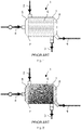
- Figure 1 shows elements expected to be found in a known oxygenator 1 used in extracorporeal ventilation.
- the oxygenator 1 is provided to expose oxygen-reduced, or venous, blood to a gas supply comprising oxygen and a low percentage of carbon dioxide.
- the carbon dioxide percentage in the supplied gas may be practically 0.
- the oxygenator 1 comprises a blood passage comprising blood inlet 2 via which venous blood is supplied into the oxygenator 1 and a blood outlet 3 via which outgoing blood leaves the oxygenator 1 for further use, often as arterial blood to be returned to a patient.
- the oxygenator 1 also comprises a gas passage comprising a sweep gas supply 4 leading via an inlet chamber 5 through a gas-blood interface 7 and via an exhaust chamber 8 to an exhaust passage 9.
- Modern gas-blood interfaces typically comprise a bundle of several thousand hollow, micro-porous fibres with micro-porous, gas-permeable properties.
- the sweep gas is supplied through the interior, hollow space of the fibres and blood flows around the fibres and gas exchange is promoted by relative gas-transfer gradients between the concentrations of oxygen and carbon dioxide in blood and gas, respectively.
- the hollow fibres are held together at their ends by typically a resin, so-called potting 7, which seals off the blood passage from the inlet chamber 5 and the exhaust chamber 8.
- the design is such that the gas flow conditions, in particular flow rate and volumes, from the inlet chamber 5 through the gas-blood interface 6 are, as much as is controllable, expected to be homogeneous, as would be expected from a single, static gas supply port.
- the gas composition and pressure will change along the hollow fibres from the inlet-facing potting 7 towards outlet-facing potting 7, because the oxygen content is gradually reducing as blood picks up oxygen molecules, and the carbon dioxide content is gradually increasing due to diffusion from blood carbon dioxide into the oxygenation gas.
- the gas flow conditions through the hollow fibres are determined by parameters of the sweep gas supply 4 and are practically homogeneous.
- the aim of such an oxygenator type is to modulate the partial pressure of oxygen PaO2 in the outgoing blood.
- the aim may also be to modulate the partial pressure of carbon dioxide PaCO2 in the outgoing blood.
- PaO2 may be modulated by adjusting the oxygen percentage (ie partial oxygen pressure) of the oxygenation gas, the remaining component being mainly nitrogen.
- PaCO2 may be modulated by adjusting the flow rate of the oxygenation gas.
- an oxygenation gas supply system such as described in WO2016/087859 and WO2016/087861 by the present applicant, both the composition and the flow rate of the oxygenation gas can be controlled simultaneously, allowing both the PaO2 and PaCO2 that is expected in the outgoing blood to be modulated simultaneously.
- Figure 2 illustrates, schematically, the carbon dioxide gas-transfer gradient of an oxygenator 1 in use.
- the same numerals are used in Figures 2 and 1 for the same components, and the description of the same components is not repeated where this corresponds to Figure 1 .
- the exchange of blood gas with supplied gas components is driven by a gradient across the membrane (from the inside of the hollow fibres towards the outside of the hollow fibres). The higher the gradient, the more effective the gas transfer.
- Figure 2 illustrates the gradient that drives the transfer of carbon dioxide from the blood to the gas passage.
- the blood Upon entering the gas-blood interface the blood is exposed to fresh supply gas from the sweep gas supply 4 with a carbon dioxide partial pressure of practically nil. Initially, there is a high gas-transfer gradient causing carbon dioxide transfer into the gas passage. As the blood flows through the gas-blood interface 6 towards the blood outlet 3 (flowing down in the reading orientation of Figure 2 ), the blood carbon dioxide decreases and so the gas-transfer gradient decreases relative to the supply gas. Furthermore, along the gas passage (in the reading orientation of Figure 2 , from the inlet chamber 5 on the left to the exhaust chamber 8 on the right), the partial pressure of carbon dioxide in the supply gas increases and so the gas-transfer gradient decreases.
- the gas-transfer gradient decreases across the gas-blood interface (a) in the direction of the blood flow path (b) in the direction of the gas passage.
- the carbon dioxide gas-transfer gradient is schematically indicated by lighter and darker dithering within the gas-blood interface 6; a lighter dithering indicates a gas-transfer gradient, more likely to promote removal of carbon dioxide from the blood. A darker dithering indicates a lower gas-transfer gradient, with a slower carbon dioxide removal rate than a light dithering area.
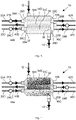
- FIG. 3 shows an oxygenator 10 in accordance with embodiments of the invention.
- the oxygenator 10 comprises a blood inlet 12 and a blood outlet 14 providing a blood passage through the oxygenator 10.
- the oxygenator 10 comprises a gas-blood interface 32 in which a plurality of hollow fibres are provided which are held together as bundle by potting 30 at one end and by potting 36 at the other end.
- the space outside the potting 30,36 of the gas-blood interface 32 provides gas chambers, one on each side of the gas-blood interface. Each gas chamber provides a gas passage with the gas-blood interface 32.
- the oxygenator 10 comprises three gas paths, each of which leads via a gas supply towards a gas chamber, through the gas passages of the gas-blood interface, and via the opposite gas chamber into an exhaust line.
- the first gas path comprises a first sweep gas supply 22A with a first sweep gas flow controller 24A to provide supply gas towards the gas-blood interface 32.
- the first gas path leads via a first inlet compartment 26A in the first gas chamber through potting 30 into the gas-blood interface 32, in particular into a first group 34A of hollow fibres, and from the gas-blood interface 32 through the potting 36 into a first exhaust compartment 40A of the second gas chamber, from where exhaust gas is removed via a first exhaust line 42A.
- the second gas path corresponds in sequence to the first gas path and its integers are provided with a suffix "-B" instead of "-A".
- the second gas path extends in the opposite direction of the first gas path and comprises a second sweep gas supply 22B with a second sweep gas flow controller 24B to provide supply gas towards the gas-blood interface 32.
- the second gas path leads via a second inlet compartment 26B, which, due to the opposite orientation of the second gas path, is in the second gas chamber, through potting 36 into the gas-blood interface 32, in particular into a second group 34B of hollow fibres, and from the gas-blood interface 32 through the potting 30 into a second exhaust compartment 40B which is in the first gas chamber, from where exhaust gas is removed via a second exhaust line 42B.
- the third gas path corresponds in sequence and direction to the first gas path and its integers are provided with a suffix "-C" instead of "-A".
- the third gas path extends parallel to the first gas path and in the opposite direction of the second gas path, and comprises a third sweep gas supply 22C with a third sweep gas flow controller 24C to provide supply gas towards the gas-blood interface 32.
- the third gas path leads via a third inlet compartment 26C in the first gas chamber, through potting 30 into the gas-blood interface 32, in particular into a third group 34C of hollow fibres, and from the gas-blood interface 32 through the potting 36 into a third exhaust compartment 40C in the second gas chamber, from where exhaust gas is removed via a third exhaust line 42C.
- the oxygenator 10 comprises a housing that is gas tight at the gas inlet areas.
- the first, second and third inlet compartments 26A, 26B and 26C are gas tight to avoid contamination of the supply gas before this enters the gas-blood interface 32.
- the first, second and third exhaust compartments 40A, 40B and 40C the housing may comprises several openings to allow pressure equilibration with the environment, in order to avoid a pressure build-up within the gas-blood interface 32.
- the blood passage between the blood inlet 12 and the blood outlet 14 is provided by the gas-blood interface 32 bounded by the inlet-facing potting 30 and the outlet-facing potting 36, and constituted by the space inside the potting surrounding the hollow fibres 34.
- the oxygenator 10 comprises a plurality (here: four) of partitions 28, namely partitions 28A, 28B, 28C and 28D.
- the partitions 28 separate each of the two gas chambers into a plurality (here: three) gas compartments.
- the first gas chamber is separated by two partitions 28A and 28B into the first inlet compartment 26A, the second exhaust compartment 40B, and the third inlet compartment 26C.
- the second chamber is separated by two partitions 28C and 28D into the first exhaust compartment 40A, the second inlet compartment 26B, and the third exhaust compartment 40C.
- Each compartment 26A, 26B, 26C and 40A, 40B, 40C can be considered as adjoining a different portion of the potting 30 or 36, respectively.
- each gas inlet compartment and each gas exhaust compartment has a different border with the gas-blood interface 32.
- the arrangement allows known oxygenator hollow fibre designs to be utilised, by addition of partitions, for a counter flow gas supply. It will be appreciated that the Figure 3 arrangement provides a plurality (here: three) gas paths, or a plurality of groups of gas passages, crossing different regions of the same blood pathway. This facilitates providing a sterile blood passage.
- the hollow fibre bundles that connect to the first inlet compartment 26A are supplyable by the first sweep gas supply 22A, and likewise, the fibres connecting to the second inlet compartment 26B are supplyable by the second sweep gas supply 22B, and the fibres connecting to the third inlet compartment 26C are supplyable by the second sweep gas supply 22C.
- the partitions 28A-28D is illustrated in a fixed position in Figure 3 .
- the partitions 28A-28D may be fixed in position, e.g. according to an oxygenator design.
- the partitions 28A-28D may be re-positionable at different locations.
- a re-positionable partition allows the number of fibres to be changed that may be supplied via the first gas passage, the second gas passage, or the third gas passage.
- re-positionable partitions facilitate the alignment of the gas inlet compartment with its corresponding gas exhaust compartment.
- the partitions 28A-28D may be moveable across the potting 30 and 36. This allows the ratio of the number, and thereby the area of, the groups of hollow fibres 34A, 34B and 34C relative to each other to be altered.
- the partitions 28A-28D may not necessarily have to seal against the potting 30 and/or 36 because a small amount of gas seeping into the respective other area (for instance from the first gas inlet compartment 26A into the second group of hollow fibres 34B) may be tolerable.
- the hollow fibres are densely packed, and the edge of a partition may be larger than a hollow fibre diameter.
- An edge of a partition in contact with the inlet-facing potting 30 or 36 may cover a certain amount of hollow fibres such that partition-covered hollow fibres are not practically supplyable with gas.
- a partition 28 is not in close contact with the respective potting 30 or 36, hollow fibres just beneath the partition may not be supplied by sweep gas and, instead, the sweep gas may be sucked around the partition into an adjoining exhaust compartment.
- Each sweep gas supply 22A, 22B and 22C is controllable separately by the respective sweep gas flow controllers 24A, 24B and 24C.
- Each sweep gas supply may be controllable separately.
- the sweep gas is understood to have a composition in which it is intended to be supplied to the gas-blood interface.
- the exhaust compartments 40A, 40B and 40C may comprise one or more openings to the outside, such as slits in the housing of the oxygenator 10.
- the openings provide auxiliary vents which provide a mechanism against over-pressurising the gas passage.
- Figure 4 illustrates, schematically, the carbon dioxide gas-transfer gradient of an oxygenator 10 in use.
- the same numerals are used in Figures 4 and 3 for the same components, and the description of the same components is not repeated where this corresponds to Figure 3 .
- the carbon dioxide gas-transfer gradient is indicated by lighter and darker dithering within the gas-blood interface 32; a lighter dithering indicates a higher carbon dioxide gas-transfer gradient, more likely to promote carbon dioxide removal from the blood.
- a darker dithering indicates a lower gas-transfer gradient, with a slower carbon dioxide removal rate than a light dithering area.
- the gas-transfer gradient in Figure 4 decreases across the gas-blood interface (a) in the direction of the blood flow path (b) in the direction of gas flow in a gas passage.
- blood flowing past the first group 34A of hollow fibres near the exhaust compartment 40A comes into contact with the second group 34B of hollow fibres that is supplied by a 'fresh' supply gas with low carbon dioxide percentage.
- the carbon dioxide percentage of the supply gas may be practically zero and so the diffusion gradient is relatively larger for subsequent gas paths, which is illustrates in Figure 4 by a lighter dithering near the second inlet compartment 26B.
- the blood exiting at blood outlet 14 has a lower partial pressure of carbon dioxide compared to the same number of hollow fibres in the Figure 2 comparison.
- the multiple gas passages are in counter flow relative to each other and cross the blood passage successively, in series, such that blood flows past each of the gas passages between the blood inlet 12 and the blood outlet 14.
- supply gas condition, flow rates and composition are set so as to achieve, for a given blood gas management device, a set blood gas composition in the outgoing blood at the blood outlet 14.
- the blood gas management device may be used to set one or more blood gas values simultaneously.
- the system may be used to set the partial pressures of oxygen and/or carbon dioxide simultaneously.
- the system provides the option to modulate the supply gas condition of each gas supply separately.
- two or more supply gas lines may be supplied by the same source of gas and distributed to the gas-blood interface via a manifold.
- the supply gas may have the same composition, supplied by a common source, and the flow rate through each passage is modulated separately.
- the exhaust gas removal may be carried out for each gas passage separately, or using a common exhaust gas extraction source for two or more gas passages.
- Figure 5 illustrates a variant of Figure 3 .
- the same numerals are used in Figures 5 and 3 for the same components, and the description of the same components is not repeated where this corresponds to Figure 3 .
- the three exhaust lines 42A, 42B and 42C lead into a manifold 44 from which exhaust gases are removed via a common exhaust line 46.
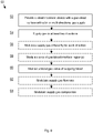
- FIG. 6 illustrates a method 50 of managing the transfer of blood gas.
- the method 50 comprises a step 52 of providing a blood treatment device such as the device 10 or 10A of Figures 3 or 5 , which comprises a gas-blood interface and a configuration to supply gas from two or more directions relative to the direction of the blood flow path.
- a blood treatment device such as the device 10 or 10A of Figures 3 or 5 , which comprises a gas-blood interface and a configuration to supply gas from two or more directions relative to the direction of the blood flow path.
- supply gas is provided to cross the blood flow path in at least two directions.
- the supply gas is modulated differently for at least one of the directions than for another one of the directions.
- the available gas-blood interface region is modulated, for instance by stopping supply of gas through one or more of the gas passages.
- a blood gas value of the outgoing blood is measured.
- gas parameters are altered in response to the outgoing blood value.
- a mechanism may be used to provide a closed loop control.
- the flow rate of one or more of the gas supplies is modulated.
- the composition of one or more of the gas supplies is modulated.
- the arrangements described herein allow the use of a single hollow fibre assembly to be used as interface with multiple gas passages.
- the individual gas passages are defined by partitions in the gas chambers outside the hollow fibre interface. This facilitates providing a sterile environment for the blood passage, whereby blood has to be channelled through only a single blood treatment device.
- the invention has been devised with the ability to utilise existing fibre membrane interface geometries, initial calculations indicate that the invention may be even more effective in different interface geometries.
- the carbon-dioxide removing effect can be maintained with longer gas passages, which allows fewer fibres to be used to achieve the same surface area of the gas-blood interface.
- this allows much shorter blood passages to be used, which firstly reduces the mechanical strain otherwise exerted on blood cells due to the shorter travel distance for the blood, but furthermore reduces the driving pressure otherwise required to push the blood past the otherwise many thousand fibres.
- a shorter blood path reduces the pumping power required to drive blood through the blood gas treatment device, which allows much smaller pumps to be used.
- the invention enables much smaller blood gas treatment devices, with longer gas passages than would be practical for mono-directional gas supply systems, yet with a shorter blood passage with fewer fibres to provide the same gas-blood interface area.
- the invention may enable wearable, even implantable blood gas treatment devices.
- the blood gas treatment device may comprise gas passages that within the gas-blood interface comprise at least double the length of the blood passage, or whose length is a more than 3x, 4x, 5x, the length of the blood passage measured, wherein the length of a gas passage is measured from the inlet of the gas-blood interface to the exhaust end of the gas-blood interface and the length of the blood passage is the direct distance from the blood inlet into the gas-blood interface to the blood outlet from the gas-blood interface.
- Oxygenators may comprise more complex blood flow and gas flow geometries.
- the invention is described in relation to a blood gas management device.
- the blood gas management device may be part of a blood gas management system.
- the blood gas management system may comprise components for conditioning the supply gas and for providing the supply gas towards the blood gas management device.
- the blood gas management system may comprise components for removing exhaust gas.
- the blood gas management system may comprise sensor arrangements and controllers to execute a closed loop control of the flow rates.
- Sensors may be arranged to measure values at the gas inlet and/or gas outlet of each gas path, in particular at the gas inlet and/or gas outlet of an interface gas passage.
- Sensors may be arranged to measure blood values before and after a gas flow path. For instance, one or more sensors may be arranged to measure blood values at the blood inlet, before the blood passes the first gas path, between two gas paths, and/or at the blood outlet, after the blood has passed all gas paths.
Landscapes
- Health & Medical Sciences (AREA)
- Heart & Thoracic Surgery (AREA)
- Urology & Nephrology (AREA)
- Emergency Medicine (AREA)
- Vascular Medicine (AREA)
- Life Sciences & Earth Sciences (AREA)
- Biomedical Technology (AREA)
- Hematology (AREA)
- Anesthesiology (AREA)
- Animal Behavior & Ethology (AREA)
- General Health & Medical Sciences (AREA)
- Public Health (AREA)
- Veterinary Medicine (AREA)
- Engineering & Computer Science (AREA)
- Cardiology (AREA)
- External Artificial Organs (AREA)
Description
- The present invention relates to a system for removing carbon dioxide from blood in systems that bypass the lung, such as extracorporeal blood oxygenation and carbon dioxide control.
- Blood gas treatment devices, such as extracorporeal membrane oxygenators, allow a blood gas composition to be modulated by exposing blood to a supply gas via a gas-blood interface. The gas-blood interface may be provided in the form of gas-permeable walls of hollow fibres, wherein gas passes through the interior lumen of the hollow fibres and blood flows across the outside of the hollow fibres. Gas exchange across the gas-permeable walls is encouraged by a partial pressure gradient of relative partial pressures between the blood gas the supply gas. After the gas exchange, the supplied gas is removed as exhaust gas.
- In extracorporeal membrane oxygenation, the partial pressure of oxygen in the outgoing blood (outgoing blood being the blood leaving the blood gas treatment device) is controllable by adjusting the composition of the supply gas. The partial pressure of carbon dioxide in the outgoing blood is controllable by adjusting the flow rate of the supply gas past the gas blood interface.
- International patent application
PCT/GB2015/053694 WO2016/087859 , discloses an oxygenation system with a flow control arrangement for controlling the flow rate of the exhaust gas relative to the supply gas.WO2016/087859 also discloses a blender for preparing a supply gas with a high-accuracy oxygen content at low flow rates. The blender and flow control arrangement disclosed inWO2016/087859 can be used to maintain low flow rates of a supply gas while also permitting a high degree of blending accuracy and while permitting exhaust gas to be withdrawn at an appropriate flow rate that is low, yet higher than the oxygenation gas supply. A system likeWO2016/087859 allows a simultaneous modulation of the partial pressure of oxygen and carbon dioxide in the outgoing blood.WO2017/211460 A1 relates to a gas exchange unit for use in extracorporeal membrane oxygenation or extracorporeal live support, wherein the gas is provided to the gas-blood interface from different directions relative to the blood flow path. - The present invention seeks to provide further improvements over existing blood gas exchange devices.
- In accordance with a first aspect of the invention, there is provided a blood gas management device as defined by
claim 1. The blood gas management device comprises a plurality of gas passages each comprising a gas inlet and a gas outlet, and a blood passage arranged with a gas-blood interface with the gas passages. The blood gas management device is arranged to allow a flow of supply gas from the gas inlets through the gas passages to the gas outlets, and to allow a flow of blood in a blood flow path through the blood passage to thereby permit an exchange of blood gas with the supply gas via the gas-blood interface. The blood gas management device comprises a supply gas distribution arrangement allowing the supply gas to be provided to the gas-blood interface from different directions relative to the blood flow path. Two or more multidirectional gas passages are arranged in series relative to the blood flow path, so that the blood is exposed to a first gas passage before being exposed to a second gas passage. - The layout of a blood gas management device can be visualised as a plurality of gas passages (for instance, several thousands of hollow fibres) between a gas inlet and leading through to a gas exhaust. Blood is allowed to flow across the outside of the gas passages.
- The present mechanism is based on the appreciation that the majority of carbon dioxide movement out of the blood and into the exhaust gas occurs relatively early in the gas-blood interface. The gas exchange is driven by the differential of the partial pressures of carbon dioxide in the blood and in the gas passage. In the present specification, the expression "gradient" may be used to refer to the differential. Due to the mobility of carbon dioxide, the differential decreases quickly along the gas passage. Therefore, fairly soon along the gas passage, the differential and, therefore, the gradient driving the gas transfer is reduced.
- In existing systems, the carbon dioxide exchange can be modulated by changing the gas flow rate. By way of illustration, an increased gas flow rate achieves that more "fresh" supply gas is transported further into the gas passage per unit time. However, a limit is placed on gas flow modulation by practical considerations, such as maintaining a defined gas exchange of other gas components such as oxygen.
- The present mechanism provides a better gas-transfer gradient over the length of the gas passage. The better gas-transfer gradient is achieved by supplying gas from different directions relative to the blood flow path. This allows fresh supply gas, with a higher differential of partial pressures of a relevant gas component, to be directed towards blood in downstream regions of the gas passage. By "fresh" supply gas, a supply gas is meant that has not yet been exposed to the blood in the gas-blood interface.
- The gas supply from different directions may be a bi-directional or multi-directional gas supply, in which gas is supplied along two or more different directions relative to the blood flow path, in particular through the gas-blood interface. The gas supply may be ambi-directional with two or more gas passages arranged in counter flow relative to the flow of blood.
- In some embodiments, the supply gas distribution arrangement is configured to provide a first supply of gas to cross at least part or all the blood flow path in a first direction and to provide a second supply of gas to cross at least part or all the blood flow path in a second direction different from the first direction.
- The first and second supply may be of the same composition or of different composition. The first and second supply may have the same flow rate or different flow rates.
- In some embodiments, at least one gas passage comprises a gas inlet in the direction of the gas outlets of another gas passage, whereby the at least one gas passage is configured to direct gas in counter flow to the other gas passage.
- A counter flow arrangement allows the invention to be implemented with parallel gas passages. This may facilitate the construction of a blood gas management device. For instance, this may facilitate the design of the gas supplies.
- As mentioned above, at least two or more multidirectional gas passages are arranged in series relative to the blood flow path.
- By an arrangement in series it is meant that, in the direction of the blood flow, a first gas passage crosses the blood upstream of a second gas passage. Thereby, blood flowing across the gas passages is exposed to the first gas passage before being exposed to the second gas passage.
- In some embodiments, the blood gas management device further comprises an exhaust removal system configured to extract exhaust gas from gas outlets in different directions relative to the flow of blood.
- The exhaust gas removal system may be configured as described in
WO2016/087859 . The exhaust gas removal system may allow the exhaust gas flow rate of a gas passage to be modulated relative to the supply gas flow rate of the gas passage. For instance, the exhaust gas flow rate may be modulated, by way of a closed loop control, to match or exceed the supply gas flow rate. - In some embodiments, the exhaust gas removal system comprises a common connection to different gas outlets of multidirectional gas passages.
- The exhaust gas removal system may be assisted by a vacuum or other suitable low-pressure source. The exhaust gas removal system may comprise auxiliary vents in the exhaust compartments of the gas passage. The auxiliary vents provide a safe-guard mechanism against over pressurisation at the gas-blood interface.
- In some embodiments, at least some or all of the gas passages are provided by hollow fibres comprising gas-permeable walls.
- It will be understood that the gas-permeability refers to the wall of the hollow fibre to allow gas exchange from the inside of the fibre, supplied by gas, across the wall to the outside of the fibre, where blood is allowed to flow.
- In some embodiments, the blood gas management device is comprised in an extracorporeal oxygenator with a gas chamber at each end of the gas passages, wherein each gas chamber is separated into a plurality of compartments, each compartment allowing gas to be directed via a separate group of gas passages.
- Existing oxygenator designs have a defined gas passage with an inlet zone and an exhaust zone. For example, a hollow-fibre oxygenator, which is a common oxygenator design, comprises many thousand hollow fibres each providing a gas passage from an inlet to an exhaust. One end of each fibre leads into a gas inlet zone and the other end of each fibre leads into a gas exhaust zone. The present invention is based on the appreciation that such known hollow fibre designs may be modified by supplying at least some gas in counter flow, i.e. a portion of the gas is supplied in a direction from what would conventionally be the gas exhaust zone towards what would conventionally be the gas inlet zone.
- A gas chamber may be separated into a plurality of compartments by one or more partitions, each section having a border with a different region of the gas-blood interface.
- In some embodiments, the blood gas management device comprises a gas sensor arrangement configured to obtain at least one gas value of a supply gas entering the gas inlet and/or exiting the gas outlet, wherein the at least one gas value comprises a gas flow rate, a gas pressure, and/or the percentage of carbon dioxide, oxygen, nitrogen, and/or a combination thereof.
- In some embodiments, the blood gas management device comprises a blood sensor arrangement configured to obtain at least one blood value of the blood entering and/or exiting the gas-blood interface, wherein the at least one blood value comprises a blood flow rate, blood pressure, blood temperature, and/or the percentage of carbon dioxide, oxygen, nitrogen, and/or a combination thereof.
- In some embodiments, the blood gas management device comprises a supply gas control system configured to receive as input one or more blood values or one or more gas values to modulate at least one gas flow parameter in response to the gas value and/or the blood value, wherein the at least one gas flow parameter comprises a composition and/or a flow rate of the supply gas.
- The above-mentioned sensor arrangements and control system arrangements may be part of a blood gas management control system. The arrangements may be operationally linked with the blood gas management device and may be located outside the device's housing.
- The supply of the gas through the multi-directional gas passages may be modulated in terms of gas composition and/or gas flow rate. Together with a sensor arrangement and control system this provides a closed loop control, or a feedback loop, that facilitates automatically modulating the blood gas value towards a set value or towards a target value.
- Sensors, operationally linked with a mechanism controlling the flow rate and/or composition of the gas and or blood, respectively, allow a closed loop control to modulate the supply gas and/or blood stream to maintain a specific property, such as PaO2, PaCO2, and/or temperature, at a predetermined set point.
- By "maintaining" a property, it is meant that the system is responsive to compensate gas parameters (flow, composition) to thereby compensate for temporary fluctuations about the predetermined set point.
- For instance, a sensor may record that the blood carbon dioxide of blood having crossed a first number of fibres with a gas supply in a first direction and a second number of fibres with a gas supply in a second direction is not low enough, relative to a target carbon dioxide level. A control system may determine that the carbon dioxide level in the outgoing blood cannot be lowered by altering the gas flow rate of the first gas supply, for instance because this would undesirably affect the oxygenation performance. The blood gas management device may in that case modulate the flow rate and/or composition of the gas supply in the second direction to further reduce the blood carbon dioxide value, to avoid modulating the first gas supply.
- Also disclosed herein, but not claimed, is a method of using a blood gas management device. The blood gas management device comprises a plurality of gas passages each comprising a gas inlet and a gas outlet, and a blood passage having a gas-blood interface with the gas passages. The method comprises the steps of: directing a flow of supply gas from the gas inlets through the gas passages to the gas outlets, and allowing a flow of blood in a blood flow path through the blood passage to thereby permit an exchange of blood gas with the supply gas via the interface. The method further comprises providing the supply gas to the gas-blood interface from different directions relative to the blood flow path.
- The method may comprise providing a first supply of gas to cross at least part or all the blood flow path in a first direction and providing a second supply of gas to cross at least part or all the blood flow path in a second direction different from the first direction, and optionally providing the second supply of gas in counter flow to the first supply of gas.
- The method may comprise providing at least two or more multidirectional gas passages in series relative to the blood flow path.
- The method may comprise extracting exhaust gas from gas outlets in different directions relative to the flow of blood, and optionally extracting the exhaust gas using a common exhaust gas removal system connected to different gas outlets of multidirectional gas passages.
- The method may be used in an extracorporeal oxygenator with a gas chamber at each end of the gas passages, wherein each gas chamber is separated into a plurality of compartments, wherein the method comprises directing different supplies of gas via a separate group of gas passages.
- The method may comprise using a gas sensor arrangement to obtain at least one gas value of a supply gas entering the gas inlet and/or exiting the gas outlet, wherein the at least one gas value comprises carbon dioxide, oxygen, nitrogen, and/or a combination thereof.
- The method may comprise a blood sensor arrangement configured to obtain at least one blood value of the blood entering and/or exiting the gas-blood interface, wherein the at least one blood value comprises carbon dioxide, oxygen, nitrogen, or a combination thereof.
- The method may comprise using a feedback loop to modulate at least one gas flow parameter in response to the gas value and/or the blood value, wherein the at least one gas flow parameter comprises a composition and/or a flow rate of the supply gas.
- In some embodiments of the blood gas management device, the plurality of gas passages is part of an oxygenator or of a carbon dioxide management device.
- Optionally, the oxygenator or the device is an extracorporeal device, a wearable device, or an implantable device.
- Exemplary embodiments of the invention will now be described with reference to the Figures, in which:
-
Figure 1 shows a prior art oxygenator arrangement; -
Figure 2 illustrates a gas-transfer gradient expected during operation of aFigure 1 device; -
Figure 3 is a schematic illustration of a blood gas management device; -
Figure 4 illustrates gas-transfer gradients expected in one mode of operation of aFigure 3 device; -
Figure 5 is a schematic illustration of another blood gas management device; and -
Figure 6 shows steps of a sequence of a blood gas management method. -
Figure 1 shows elements expected to be found in a knownoxygenator 1 used in extracorporeal ventilation. Theoxygenator 1 is provided to expose oxygen-reduced, or venous, blood to a gas supply comprising oxygen and a low percentage of carbon dioxide. The carbon dioxide percentage in the supplied gas may be practically 0. During a gas exchange between the blood and the gas supply the blood is oxygenated and carbon dioxide is removed in order to provide oxygen-enriched and carbon dioxide reduced arterial blood. Theoxygenator 1 comprises a blood passage comprisingblood inlet 2 via which venous blood is supplied into theoxygenator 1 and ablood outlet 3 via which outgoing blood leaves theoxygenator 1 for further use, often as arterial blood to be returned to a patient. Theoxygenator 1 also comprises a gas passage comprising asweep gas supply 4 leading via aninlet chamber 5 through a gas-blood interface 7 and via anexhaust chamber 8 to anexhaust passage 9. - Modern gas-blood interfaces typically comprise a bundle of several thousand hollow, micro-porous fibres with micro-porous, gas-permeable properties. The sweep gas is supplied through the interior, hollow space of the fibres and blood flows around the fibres and gas exchange is promoted by relative gas-transfer gradients between the concentrations of oxygen and carbon dioxide in blood and gas, respectively. The hollow fibres are held together at their ends by typically a resin, so-called
potting 7, which seals off the blood passage from theinlet chamber 5 and theexhaust chamber 8. The design is such that the gas flow conditions, in particular flow rate and volumes, from theinlet chamber 5 through the gas-blood interface 6 are, as much as is controllable, expected to be homogeneous, as would be expected from a single, static gas supply port. It will be understood that, in operation, the gas composition and pressure will change along the hollow fibres from the inlet-facingpotting 7 towards outlet-facingpotting 7, because the oxygen content is gradually reducing as blood picks up oxygen molecules, and the carbon dioxide content is gradually increasing due to diffusion from blood carbon dioxide into the oxygenation gas. However, for a given distance from theinlet chamber 5, the gas flow conditions through the hollow fibres are determined by parameters of thesweep gas supply 4 and are practically homogeneous. - The aim of such an oxygenator type is to modulate the partial pressure of oxygen PaO2 in the outgoing blood. The aim may also be to modulate the partial pressure of carbon dioxide PaCO2 in the outgoing blood. PaO2 may be modulated by adjusting the oxygen percentage (ie partial oxygen pressure) of the oxygenation gas, the remaining component being mainly nitrogen. PaCO2 may be modulated by adjusting the flow rate of the oxygenation gas. Using an oxygenation gas supply system such as described in
WO2016/087859 andWO2016/087861 by the present applicant, both the composition and the flow rate of the oxygenation gas can be controlled simultaneously, allowing both the PaO2 and PaCO2 that is expected in the outgoing blood to be modulated simultaneously. -
Figure 2 illustrates, schematically, the carbon dioxide gas-transfer gradient of anoxygenator 1 in use. The same numerals are used inFigures 2 and 1 for the same components, and the description of the same components is not repeated where this corresponds toFigure 1 . The exchange of blood gas with supplied gas components is driven by a gradient across the membrane (from the inside of the hollow fibres towards the outside of the hollow fibres). The higher the gradient, the more effective the gas transfer.Figure 2 illustrates the gradient that drives the transfer of carbon dioxide from the blood to the gas passage. As venous blood enters viablood inlet 2, in the reading orientation ofFigure 2 in the top left corner, the blood has a relatively high partial pressure of carbon dioxide. Upon entering the gas-blood interface the blood is exposed to fresh supply gas from thesweep gas supply 4 with a carbon dioxide partial pressure of practically nil. Initially, there is a high gas-transfer gradient causing carbon dioxide transfer into the gas passage. As the blood flows through the gas-blood interface 6 towards the blood outlet 3 (flowing down in the reading orientation ofFigure 2 ), the blood carbon dioxide decreases and so the gas-transfer gradient decreases relative to the supply gas. Furthermore, along the gas passage (in the reading orientation ofFigure 2 , from theinlet chamber 5 on the left to theexhaust chamber 8 on the right), the partial pressure of carbon dioxide in the supply gas increases and so the gas-transfer gradient decreases. In summary, the gas-transfer gradient decreases across the gas-blood interface (a) in the direction of the blood flow path (b) in the direction of the gas passage. The carbon dioxide gas-transfer gradient is schematically indicated by lighter and darker dithering within the gas-blood interface 6; a lighter dithering indicates a gas-transfer gradient, more likely to promote removal of carbon dioxide from the blood. A darker dithering indicates a lower gas-transfer gradient, with a slower carbon dioxide removal rate than a light dithering area. -
Figure 3 shows anoxygenator 10 in accordance with embodiments of the invention. Theoxygenator 10 comprises ablood inlet 12 and ablood outlet 14 providing a blood passage through theoxygenator 10. Theoxygenator 10 comprises a gas-blood interface 32 in which a plurality of hollow fibres are provided which are held together as bundle by potting 30 at one end and by potting 36 at the other end. Within theoxygenator 10, the space outside thepotting blood interface 32 provides gas chambers, one on each side of the gas-blood interface. Each gas chamber provides a gas passage with the gas-blood interface 32. - The
oxygenator 10 comprises three gas paths, each of which leads via a gas supply towards a gas chamber, through the gas passages of the gas-blood interface, and via the opposite gas chamber into an exhaust line. - The first gas path comprises a first
sweep gas supply 22A with a first sweepgas flow controller 24A to provide supply gas towards the gas-blood interface 32. The first gas path leads via afirst inlet compartment 26A in the first gas chamber through potting 30 into the gas-blood interface 32, in particular into afirst group 34A of hollow fibres, and from the gas-blood interface 32 through the potting 36 into afirst exhaust compartment 40A of the second gas chamber, from where exhaust gas is removed via afirst exhaust line 42A. - The second gas path corresponds in sequence to the first gas path and its integers are provided with a suffix "-B" instead of "-A". The second gas path extends in the opposite direction of the first gas path and comprises a second
sweep gas supply 22B with a second sweepgas flow controller 24B to provide supply gas towards the gas-blood interface 32. The second gas path leads via asecond inlet compartment 26B, which, due to the opposite orientation of the second gas path, is in the second gas chamber, through potting 36 into the gas-blood interface 32, in particular into asecond group 34B of hollow fibres, and from the gas-blood interface 32 through the potting 30 into asecond exhaust compartment 40B which is in the first gas chamber, from where exhaust gas is removed via asecond exhaust line 42B. - The third gas path corresponds in sequence and direction to the first gas path and its integers are provided with a suffix "-C" instead of "-A". The third gas path extends parallel to the first gas path and in the opposite direction of the second gas path, and comprises a third
sweep gas supply 22C with a third sweepgas flow controller 24C to provide supply gas towards the gas-blood interface 32. The third gas path leads via athird inlet compartment 26C in the first gas chamber, through potting 30 into the gas-blood interface 32, in particular into athird group 34C of hollow fibres, and from the gas-blood interface 32 through the potting 36 into athird exhaust compartment 40C in the second gas chamber, from where exhaust gas is removed via athird exhaust line 42C. - The
oxygenator 10 comprises a housing that is gas tight at the gas inlet areas. In particular, the first, second and third inlet compartments 26A, 26B and 26C are gas tight to avoid contamination of the supply gas before this enters the gas-blood interface 32. At the other end, the first, second andthird exhaust compartments blood interface 32. - The blood passage between the
blood inlet 12 and theblood outlet 14 is provided by the gas-blood interface 32 bounded by the inlet-facingpotting 30 and the outlet-facingpotting 36, and constituted by the space inside the potting surrounding the hollow fibres 34. - Within the gas chambers, the
oxygenator 10 comprises a plurality (here: four) of partitions 28, namelypartitions oxygenator 10, the first gas chamber is separated by twopartitions first inlet compartment 26A, thesecond exhaust compartment 40B, and thethird inlet compartment 26C. At the other end of theoxygenator 10, the second chamber is separated by twopartitions first exhaust compartment 40A, thesecond inlet compartment 26B, and thethird exhaust compartment 40C. - Each
compartment blood interface 32. The arrangement allows known oxygenator hollow fibre designs to be utilised, by addition of partitions, for a counter flow gas supply. It will be appreciated that theFigure 3 arrangement provides a plurality (here: three) gas paths, or a plurality of groups of gas passages, crossing different regions of the same blood pathway. This facilitates providing a sterile blood passage. - The hollow fibre bundles that connect to the
first inlet compartment 26A are supplyable by the firstsweep gas supply 22A, and likewise, the fibres connecting to thesecond inlet compartment 26B are supplyable by the secondsweep gas supply 22B, and the fibres connecting to thethird inlet compartment 26C are supplyable by the secondsweep gas supply 22C. - The
partitions 28A-28D is illustrated in a fixed position inFigure 3 . Thepartitions 28A-28D may be fixed in position, e.g. according to an oxygenator design. Thepartitions 28A-28D may be re-positionable at different locations. A re-positionable partition allows the number of fibres to be changed that may be supplied via the first gas passage, the second gas passage, or the third gas passage. Furthermore, re-positionable partitions facilitate the alignment of the gas inlet compartment with its corresponding gas exhaust compartment. Thepartitions 28A-28D may be moveable across thepotting hollow fibres - The
partitions 28A-28D may not necessarily have to seal against the potting 30 and/or 36 because a small amount of gas seeping into the respective other area (for instance from the firstgas inlet compartment 26A into the second group ofhollow fibres 34B) may be tolerable. Also, the hollow fibres are densely packed, and the edge of a partition may be larger than a hollow fibre diameter. An edge of a partition in contact with the inlet-facingpotting respective potting - Each
sweep gas supply gas flow controllers - The exhaust compartments 40A, 40B and 40C may comprise one or more openings to the outside, such as slits in the housing of the
oxygenator 10. The openings provide auxiliary vents which provide a mechanism against over-pressurising the gas passage. -
Figure 4 illustrates, schematically, the carbon dioxide gas-transfer gradient of anoxygenator 10 in use. The same numerals are used inFigures 4 and 3 for the same components, and the description of the same components is not repeated where this corresponds toFigure 3 . Similarly toFigure 2 , the carbon dioxide gas-transfer gradient is indicated by lighter and darker dithering within the gas-blood interface 32; a lighter dithering indicates a higher carbon dioxide gas-transfer gradient, more likely to promote carbon dioxide removal from the blood. A darker dithering indicates a lower gas-transfer gradient, with a slower carbon dioxide removal rate than a light dithering area. - As in
Figure 2 , the gas-transfer gradient inFigure 4 decreases across the gas-blood interface (a) in the direction of the blood flow path (b) in the direction of gas flow in a gas passage. However, in contrast toFigure 2 , due to the presence of three gas paths in counter flow in theFigure 4 arrangement, blood flowing past thefirst group 34A of hollow fibres near theexhaust compartment 40A comes into contact with thesecond group 34B of hollow fibres that is supplied by a 'fresh' supply gas with low carbon dioxide percentage. The carbon dioxide percentage of the supply gas may be practically zero and so the diffusion gradient is relatively larger for subsequent gas paths, which is illustrates inFigure 4 by a lighter dithering near thesecond inlet compartment 26B. After passing multiple (here: three) gas passages in counter flow, the blood exiting atblood outlet 14 has a lower partial pressure of carbon dioxide compared to the same number of hollow fibres in theFigure 2 comparison. - As illustrated in
Figure 4 , the multiple gas passages are in counter flow relative to each other and cross the blood passage successively, in series, such that blood flows past each of the gas passages between theblood inlet 12 and theblood outlet 14. - Note that the number of hollow fibres of the comparison in
Figure 1 and the embodiment ofFigure 3 may be identical. Indeed it is envisaged that the invention may be used with known hollow fibre interface designs. TheFigure 3 embodiment achieves a better carbon dioxide removal than theFigure 1 comparison by way of providing supply gas from different directions relative to the blood flow path. - It will be understood that the supply gas condition, flow rates and composition are set so as to achieve, for a given blood gas management device, a set blood gas composition in the outgoing blood at the
blood outlet 14. - The blood gas management device may be used to set one or more blood gas values simultaneously. For instance, the system may be used to set the partial pressures of oxygen and/or carbon dioxide simultaneously. The system provides the option to modulate the supply gas condition of each gas supply separately. In embodiments, two or more supply gas lines may be supplied by the same source of gas and distributed to the gas-blood interface via a manifold. For instance, the supply gas may have the same composition, supplied by a common source, and the flow rate through each passage is modulated separately.
- Likewise, the exhaust gas removal may be carried out for each gas passage separately, or using a common exhaust gas extraction source for two or more gas passages.
-
Figure 5 illustrates a variant ofFigure 3 . The same numerals are used inFigures 5 and3 for the same components, and the description of the same components is not repeated where this corresponds toFigure 3 . In theFigure 5 arrangement the threeexhaust lines common exhaust line 46. -
Figure 6 illustrates amethod 50 of managing the transfer of blood gas. Themethod 50 comprises astep 52 of providing a blood treatment device such as thedevice Figures 3 or5 , which comprises a gas-blood interface and a configuration to supply gas from two or more directions relative to the direction of the blood flow path. Instep 54, supply gas is provided to cross the blood flow path in at least two directions. In anoptional step 56, the supply gas is modulated differently for at least one of the directions than for another one of the directions. In anoptional step 58, the available gas-blood interface region is modulated, for instance by stopping supply of gas through one or more of the gas passages. Inoptional step 60, a blood gas value of the outgoing blood is measured. Inoptional steps optional step 62, the flow rate of one or more of the gas supplies is modulated. Inoptional step 64, the composition of one or more of the gas supplies is modulated. - The arrangements described herein allow the use of a single hollow fibre assembly to be used as interface with multiple gas passages. The individual gas passages are defined by partitions in the gas chambers outside the hollow fibre interface. This facilitates providing a sterile environment for the blood passage, whereby blood has to be channelled through only a single blood treatment device.
- While the invention has been devised with the ability to utilise existing fibre membrane interface geometries, initial calculations indicate that the invention may be even more effective in different interface geometries. Particularly if used for carbon dioxide removal from blood, the carbon-dioxide removing effect can be maintained with longer gas passages, which allows fewer fibres to be used to achieve the same surface area of the gas-blood interface. In turn, this allows much shorter blood passages to be used, which firstly reduces the mechanical strain otherwise exerted on blood cells due to the shorter travel distance for the blood, but furthermore reduces the driving pressure otherwise required to push the blood past the otherwise many thousand fibres. A shorter blood path reduces the pumping power required to drive blood through the blood gas treatment device, which allows much smaller pumps to be used.
- It is therefore believed that the invention enables much smaller blood gas treatment devices, with longer gas passages than would be practical for mono-directional gas supply systems, yet with a shorter blood passage with fewer fibres to provide the same gas-blood interface area. The invention may enable wearable, even implantable blood gas treatment devices.
- In embodiments, the blood gas treatment device may comprise gas passages that within the gas-blood interface comprise at least double the length of the blood passage, or whose length is a more than 3x, 4x, 5x, the length of the blood passage measured, wherein the length of a gas passage is measured from the inlet of the gas-blood interface to the exhaust end of the gas-blood interface and the length of the blood passage is the direct distance from the blood inlet into the gas-blood interface to the blood outlet from the gas-blood interface.
- The specific embodiments have been described with three gas flow paths. This arrangement has been found in calculations to provide a good trade-off between improving a gas-transfer gradient and the complexity of the system. Fewer or more than three gas flow paths may be provided.
- The specific embodiments have been described as a counter flow arrangement. Such an arrangement is practical because it allows existing hollow-fibre interface geometries to be utilised. It will be understood that other gas distribution arrangements may be used, such as gas paths perpendicular to each other.
- Furthermore, the specific embodiments have been described with linear gas flow paths. Oxygenators may comprise more complex blood flow and gas flow geometries.
- The invention is described in relation to a blood gas management device. The blood gas management device may be part of a blood gas management system. For instance, the blood gas management system may comprise components for conditioning the supply gas and for providing the supply gas towards the blood gas management device. The blood gas management system may comprise components for removing exhaust gas.
- The blood gas management system may comprise sensor arrangements and controllers to execute a closed loop control of the flow rates. Sensors may be arranged to measure values at the gas inlet and/or gas outlet of each gas path, in particular at the gas inlet and/or gas outlet of an interface gas passage. Sensors may be arranged to measure blood values before and after a gas flow path. For instance, one or more sensors may be arranged to measure blood values at the blood inlet, before the blood passes the first gas path, between two gas paths, and/or at the blood outlet, after the blood has passed all gas paths.
Claims (11)
- A blood gas management device comprising a plurality of gas passages each comprising a gas inlet and a gas outlet, and a blood passage arranged with a gas-blood interface (32) with the gas passages,wherein the blood gas management device is arranged to allow a flow of supply gas from the gas inlets through the gas passages to the gas outlets, and to allow a flow of blood in a blood flow path through the blood passage to thereby permit an exchange of blood gas with the supply gas via the gas-blood interface,wherein the blood gas management device comprises a supply gas distribution arrangement allowing the supply gas to be provided to the gas-blood interface from different directions relative to the blood flow path, andwherein two or more multidirectional gas passages are arranged in series relative to the blood flow path, so that the blood is exposed to a first gas passage before being exposed to a second gas passage.
- The blood gas management device according to claim 1, wherein the supply gas distribution arrangement is configured to provide a first supply of gas (22A) to cross at least part or all the blood flow path in a first direction and to provide a second supply of gas (22B) to cross at least part or all the blood flow path in a second direction different from the first direction.
- The blood gas management device according to claim 1 or 2, wherein at least one gas passage comprises a gas inlet in the direction of the gas outlets of another gas passage, whereby the at least one gas passage is configured to direct gas in counter flow to the other gas passage.
- The blood gas management device according to any preceding claim, further comprising an exhaust removal system configured to extract exhaust gas from gas outlets in different directions relative to the flow of blood.
- The blood gas management device according to claim 4, wherein the exhaust gas removal system comprises a common connection (44) to different gas outlets of multidirectional gas passages.
- The blood gas management device according to any preceding claim, wherein at least some or all of the gas passages are provided by hollow fibres comprising gas-permeable walls.
- The blood gas management device according to any preceding claim, comprised in an extracorporeal oxygenator (10) with a gas chamber at each end of the gas passages, wherein each gas chamber is separated into a plurality of compartments (26A-C, 40A-C), each compartment allowing gas to be directed via a separate group of gas passages.
- The blood gas management device according to any preceding claim, comprising a gas sensor arrangement configured to obtain at least one gas value of a supply gas entering the gas inlet and/or exiting the gas outlet, wherein the at least one gas value comprises a gas flow rate, a gas pressure, and/or the percentage of carbon dioxide, oxygen, nitrogen, and/or a combination thereof.
- The blood gas management device according to any preceding claim, comprising a blood sensor arrangement configured to obtain at least one blood value of the blood entering and/or exiting the gas-blood interface, wherein the at least one blood value comprises a blood flow rate, blood pressure, blood temperature, and/or the percentage of carbon dioxide, oxygen, nitrogen, and/or a combination thereof.
- The blood gas management device according to claim 8 or 9, comprising a supply gas control system configured to receive as input one or more blood values or one or more gas values to modulate at least one gas flow parameter in response to the gas value and/or the blood value, wherein the at least one gas flow parameter comprises a composition and/or a flow rate of the supply gas.
- The blood gas management device according to any preceding claim, wherein the plurality of gas passages is part of an oxygenator (10) or of a carbon dioxide management device.
Applications Claiming Priority (2)
| Application Number | Priority Date | Filing Date | Title |
|---|---|---|---|
| GB1808381.6A GB2574015A (en) | 2018-05-22 | 2018-05-22 | Blood processing system |
| PCT/GB2019/051403 WO2019224533A1 (en) | 2018-05-22 | 2019-05-21 | Blood processing system |
Publications (2)
| Publication Number | Publication Date |
|---|---|
| EP3765117A1 EP3765117A1 (en) | 2021-01-20 |
| EP3765117B1 true EP3765117B1 (en) | 2022-06-08 |
Family
ID=62812534
Family Applications (1)
| Application Number | Title | Priority Date | Filing Date |
|---|---|---|---|
| EP19727715.5A Active EP3765117B1 (en) | 2018-05-22 | 2019-05-21 | Blood oxygenator |
Country Status (6)
| Country | Link |
|---|---|
| US (1) | US12036345B2 (en) |
| EP (1) | EP3765117B1 (en) |
| JP (1) | JP7366064B2 (en) |
| CN (1) | CN112135647B (en) |
| GB (1) | GB2574015A (en) |
| WO (1) | WO2019224533A1 (en) |
Families Citing this family (4)
| Publication number | Priority date | Publication date | Assignee | Title |
|---|---|---|---|---|
| JP7053630B2 (en) | 2016-09-22 | 2022-04-12 | クリストファー, ジェイ プロット, | Equipment and methods for in vitro conditioning of blood |
| CN120152751A (en) * | 2022-11-18 | 2025-06-13 | 频谱医疗有限公司 | Gas supply apparatus |
| GB2624451B (en) * | 2022-11-18 | 2025-06-04 | Spectrum Medical Ltd | System and method for controlling blood oxygenation |
| GB2614131B (en) * | 2022-11-18 | 2024-07-31 | Spectrum Medical Ltd | System and method for controlling blood oxygenation |
Family Cites Families (12)
| Publication number | Priority date | Publication date | Assignee | Title |
|---|---|---|---|---|
| US6004511A (en) * | 1995-09-01 | 1999-12-21 | Baxter International Inc. | Hollow fiber oxygenator |
| JP4258908B2 (en) * | 1999-09-14 | 2009-04-30 | 株式会社ジェイ・エム・エス | Oxygenator |
| GB0412315D0 (en) * | 2004-06-03 | 2004-07-07 | Chemcept Ltd | Blood/air mass exchange apparatus |
| GB2437254B (en) * | 2006-04-13 | 2010-11-17 | Haemair Ltd | Blood/air mass exchange apparatus |
| GB0704479D0 (en) * | 2007-03-08 | 2007-04-18 | Haemair Ltd | Prosthetic lung |
| JP5347601B2 (en) | 2009-03-16 | 2013-11-20 | 株式会社ジェイ・エム・エス | Blood processing equipment |
| DE102011052187A1 (en) * | 2011-07-27 | 2013-01-31 | Maquet Vertrieb Und Service Deutschland Gmbh | Arrangement for removing carbon dioxide from an extracorporeal blood stream by means of inert gases |
| EP2777801B1 (en) * | 2013-03-15 | 2019-08-28 | Maquet Cardiopulmonary AG | Device for eliminating CO2 from patient blood |
| WO2014162335A1 (en) * | 2013-04-01 | 2014-10-09 | テルモ株式会社 | Circulation device and method for controlling same |
| GB2557863B (en) | 2014-12-03 | 2020-09-16 | Spectrum Medical Ltd | Ventilation System |
| GB2533027B (en) | 2014-12-03 | 2020-06-03 | Spectrum Medical Ltd | Control system |
| DE102016010398A1 (en) * | 2016-06-10 | 2017-12-14 | Hemovent Gmbh | Gas exchange unit, method for manufacturing a gas exchange unit and set with a gas exchange unit and a humidifying and heating device |
-
2018
- 2018-05-22 GB GB1808381.6A patent/GB2574015A/en not_active Withdrawn
-
2019
- 2019-05-21 CN CN201980033388.6A patent/CN112135647B/en active Active
- 2019-05-21 WO PCT/GB2019/051403 patent/WO2019224533A1/en not_active Ceased
- 2019-05-21 US US17/054,792 patent/US12036345B2/en active Active
- 2019-05-21 EP EP19727715.5A patent/EP3765117B1/en active Active
- 2019-05-21 JP JP2020564602A patent/JP7366064B2/en active Active
Also Published As
| Publication number | Publication date |
|---|---|
| JP2021524311A (en) | 2021-09-13 |
| EP3765117A1 (en) | 2021-01-20 |
| CN112135647B (en) | 2024-04-12 |
| US20210369931A1 (en) | 2021-12-02 |
| GB2574015A (en) | 2019-11-27 |
| JP7366064B2 (en) | 2023-10-20 |
| US12036345B2 (en) | 2024-07-16 |
| CN112135647A (en) | 2020-12-25 |
| WO2019224533A1 (en) | 2019-11-28 |
| GB201808381D0 (en) | 2018-07-11 |
Similar Documents
| Publication | Publication Date | Title |
|---|---|---|
| US12036345B2 (en) | Blood processing system | |
| EP3731892B1 (en) | Oxygenation system | |
| JP7842844B2 (en) | Dual-chamber gas exchanger for respiratory support and its usage | |
| US8906688B2 (en) | Cell expansion system and methods of use | |
| EP3733225B1 (en) | Control system | |
| CN100522330C (en) | Apparatus and method for delivering water vapor to a gas | |
| CN107405441A (en) | Blood analysis instrument and method | |
| CN107183005A (en) | The apparatus and method for of organ perfusion | |
| GB2582239A (en) | Oxygenation system | |
| EP2819719B1 (en) | Appliance connectable to a device for the extracorporeal oxygenation of blood | |
| US20210121620A1 (en) | Working fluid treatment device for mass transfer between a working fluid and two fluid exchange media | |
| JP2025537815A (en) | Apparatus for controlling the supply of oxygenated gas, and cardiac perfusion system | |
| US20250313790A1 (en) | Microfluidic device for mimicking biological tissue with easy control of flow of fluid in channel | |
| US12128165B2 (en) | Dual stage degasser | |
| WO2024058775A1 (en) | Systems and methods for oxygenating blood, passive oxygenation circuits, and neonatal extracorporeal support systems | |
| CN112074305A (en) | Dialysis machine |
Legal Events
| Date | Code | Title | Description |
|---|---|---|---|
| STAA | Information on the status of an ep patent application or granted ep patent |
Free format text: STATUS: UNKNOWN |
|
| STAA | Information on the status of an ep patent application or granted ep patent |
Free format text: STATUS: THE INTERNATIONAL PUBLICATION HAS BEEN MADE |
|
| PUAI | Public reference made under article 153(3) epc to a published international application that has entered the european phase |
Free format text: ORIGINAL CODE: 0009012 |
|
| STAA | Information on the status of an ep patent application or granted ep patent |
Free format text: STATUS: REQUEST FOR EXAMINATION WAS MADE |
|
| 17P | Request for examination filed |
Effective date: 20201007 |
|
| AK | Designated contracting states |
Kind code of ref document: A1 Designated state(s): AL AT BE BG CH CY CZ DE DK EE ES FI FR GB GR HR HU IE IS IT LI LT LU LV MC MK MT NL NO PL PT RO RS SE SI SK SM TR |
|
| AX | Request for extension of the european patent |
Extension state: BA ME |
|
| DAV | Request for validation of the european patent (deleted) | ||
| DAX | Request for extension of the european patent (deleted) | ||
| GRAP | Despatch of communication of intention to grant a patent |
Free format text: ORIGINAL CODE: EPIDOSNIGR1 |
|
| STAA | Information on the status of an ep patent application or granted ep patent |
Free format text: STATUS: GRANT OF PATENT IS INTENDED |
|
| INTG | Intention to grant announced |
Effective date: 20220324 |
|
| RIN1 | Information on inventor provided before grant (corrected) |
Inventor name: BOWERS, SCOTT |
|
| GRAS | Grant fee paid |
Free format text: ORIGINAL CODE: EPIDOSNIGR3 |
|
| GRAA | (expected) grant |
Free format text: ORIGINAL CODE: 0009210 |
|
| STAA | Information on the status of an ep patent application or granted ep patent |
Free format text: STATUS: THE PATENT HAS BEEN GRANTED |
|
| AK | Designated contracting states |
Kind code of ref document: B1 Designated state(s): AL AT BE BG CH CY CZ DE DK EE ES FI FR GB GR HR HU IE IS IT LI LT LU LV MC MK MT NL NO PL PT RO RS SE SI SK SM TR |
|
| REG | Reference to a national code |
Ref country code: AT Ref legal event code: REF Ref document number: 1496473 Country of ref document: AT Kind code of ref document: T Effective date: 20220615 Ref country code: CH Ref legal event code: EP |
|
| REG | Reference to a national code |
Ref country code: DE Ref legal event code: R096 Ref document number: 602019015704 Country of ref document: DE |
|
| REG | Reference to a national code |
Ref country code: IE Ref legal event code: FG4D |
|
| REG | Reference to a national code |
Ref country code: LT Ref legal event code: MG9D |
|
| REG | Reference to a national code |
Ref country code: NL Ref legal event code: MP Effective date: 20220608 |
|
| PG25 | Lapsed in a contracting state [announced via postgrant information from national office to epo] |
Ref country code: SE Free format text: LAPSE BECAUSE OF FAILURE TO SUBMIT A TRANSLATION OF THE DESCRIPTION OR TO PAY THE FEE WITHIN THE PRESCRIBED TIME-LIMIT Effective date: 20220608 Ref country code: NO Free format text: LAPSE BECAUSE OF FAILURE TO SUBMIT A TRANSLATION OF THE DESCRIPTION OR TO PAY THE FEE WITHIN THE PRESCRIBED TIME-LIMIT Effective date: 20220908 Ref country code: LT Free format text: LAPSE BECAUSE OF FAILURE TO SUBMIT A TRANSLATION OF THE DESCRIPTION OR TO PAY THE FEE WITHIN THE PRESCRIBED TIME-LIMIT Effective date: 20220608 Ref country code: HR Free format text: LAPSE BECAUSE OF FAILURE TO SUBMIT A TRANSLATION OF THE DESCRIPTION OR TO PAY THE FEE WITHIN THE PRESCRIBED TIME-LIMIT Effective date: 20220608 Ref country code: GR Free format text: LAPSE BECAUSE OF FAILURE TO SUBMIT A TRANSLATION OF THE DESCRIPTION OR TO PAY THE FEE WITHIN THE PRESCRIBED TIME-LIMIT Effective date: 20220909 Ref country code: FI Free format text: LAPSE BECAUSE OF FAILURE TO SUBMIT A TRANSLATION OF THE DESCRIPTION OR TO PAY THE FEE WITHIN THE PRESCRIBED TIME-LIMIT Effective date: 20220608 Ref country code: BG Free format text: LAPSE BECAUSE OF FAILURE TO SUBMIT A TRANSLATION OF THE DESCRIPTION OR TO PAY THE FEE WITHIN THE PRESCRIBED TIME-LIMIT Effective date: 20220908 |
|
| REG | Reference to a national code |
Ref country code: AT Ref legal event code: MK05 Ref document number: 1496473 Country of ref document: AT Kind code of ref document: T Effective date: 20220608 |
|
| PG25 | Lapsed in a contracting state [announced via postgrant information from national office to epo] |
Ref country code: RS Free format text: LAPSE BECAUSE OF FAILURE TO SUBMIT A TRANSLATION OF THE DESCRIPTION OR TO PAY THE FEE WITHIN THE PRESCRIBED TIME-LIMIT Effective date: 20220608 Ref country code: LV Free format text: LAPSE BECAUSE OF FAILURE TO SUBMIT A TRANSLATION OF THE DESCRIPTION OR TO PAY THE FEE WITHIN THE PRESCRIBED TIME-LIMIT Effective date: 20220608 |
|
| PG25 | Lapsed in a contracting state [announced via postgrant information from national office to epo] |
Ref country code: NL Free format text: LAPSE BECAUSE OF FAILURE TO SUBMIT A TRANSLATION OF THE DESCRIPTION OR TO PAY THE FEE WITHIN THE PRESCRIBED TIME-LIMIT Effective date: 20220608 |
|
| PG25 | Lapsed in a contracting state [announced via postgrant information from national office to epo] |
Ref country code: SM Free format text: LAPSE BECAUSE OF FAILURE TO SUBMIT A TRANSLATION OF THE DESCRIPTION OR TO PAY THE FEE WITHIN THE PRESCRIBED TIME-LIMIT Effective date: 20220608 Ref country code: SK Free format text: LAPSE BECAUSE OF FAILURE TO SUBMIT A TRANSLATION OF THE DESCRIPTION OR TO PAY THE FEE WITHIN THE PRESCRIBED TIME-LIMIT Effective date: 20220608 Ref country code: RO Free format text: LAPSE BECAUSE OF FAILURE TO SUBMIT A TRANSLATION OF THE DESCRIPTION OR TO PAY THE FEE WITHIN THE PRESCRIBED TIME-LIMIT Effective date: 20220608 Ref country code: PT Free format text: LAPSE BECAUSE OF FAILURE TO SUBMIT A TRANSLATION OF THE DESCRIPTION OR TO PAY THE FEE WITHIN THE PRESCRIBED TIME-LIMIT Effective date: 20221010 Ref country code: ES Free format text: LAPSE BECAUSE OF FAILURE TO SUBMIT A TRANSLATION OF THE DESCRIPTION OR TO PAY THE FEE WITHIN THE PRESCRIBED TIME-LIMIT Effective date: 20220608 Ref country code: EE Free format text: LAPSE BECAUSE OF FAILURE TO SUBMIT A TRANSLATION OF THE DESCRIPTION OR TO PAY THE FEE WITHIN THE PRESCRIBED TIME-LIMIT Effective date: 20220608 Ref country code: CZ Free format text: LAPSE BECAUSE OF FAILURE TO SUBMIT A TRANSLATION OF THE DESCRIPTION OR TO PAY THE FEE WITHIN THE PRESCRIBED TIME-LIMIT Effective date: 20220608 Ref country code: AT Free format text: LAPSE BECAUSE OF FAILURE TO SUBMIT A TRANSLATION OF THE DESCRIPTION OR TO PAY THE FEE WITHIN THE PRESCRIBED TIME-LIMIT Effective date: 20220608 |
|
| PG25 | Lapsed in a contracting state [announced via postgrant information from national office to epo] |
Ref country code: PL Free format text: LAPSE BECAUSE OF FAILURE TO SUBMIT A TRANSLATION OF THE DESCRIPTION OR TO PAY THE FEE WITHIN THE PRESCRIBED TIME-LIMIT Effective date: 20220608 Ref country code: IS Free format text: LAPSE BECAUSE OF FAILURE TO SUBMIT A TRANSLATION OF THE DESCRIPTION OR TO PAY THE FEE WITHIN THE PRESCRIBED TIME-LIMIT Effective date: 20221008 |
|
| REG | Reference to a national code |
Ref country code: DE Ref legal event code: R097 Ref document number: 602019015704 Country of ref document: DE |
|
| PG25 | Lapsed in a contracting state [announced via postgrant information from national office to epo] |
Ref country code: AL Free format text: LAPSE BECAUSE OF FAILURE TO SUBMIT A TRANSLATION OF THE DESCRIPTION OR TO PAY THE FEE WITHIN THE PRESCRIBED TIME-LIMIT Effective date: 20220608 |
|
| PLBE | No opposition filed within time limit |
Free format text: ORIGINAL CODE: 0009261 |
|
| STAA | Information on the status of an ep patent application or granted ep patent |
Free format text: STATUS: NO OPPOSITION FILED WITHIN TIME LIMIT |
|
| PG25 | Lapsed in a contracting state [announced via postgrant information from national office to epo] |
Ref country code: DK Free format text: LAPSE BECAUSE OF FAILURE TO SUBMIT A TRANSLATION OF THE DESCRIPTION OR TO PAY THE FEE WITHIN THE PRESCRIBED TIME-LIMIT Effective date: 20220608 |
|
| 26N | No opposition filed |
Effective date: 20230310 |
|
| PG25 | Lapsed in a contracting state [announced via postgrant information from national office to epo] |
Ref country code: SI Free format text: LAPSE BECAUSE OF FAILURE TO SUBMIT A TRANSLATION OF THE DESCRIPTION OR TO PAY THE FEE WITHIN THE PRESCRIBED TIME-LIMIT Effective date: 20220608 |
|
| P01 | Opt-out of the competence of the unified patent court (upc) registered |
Effective date: 20230502 |
|
| REG | Reference to a national code |
Ref country code: CH Ref legal event code: PL |
|
| PG25 | Lapsed in a contracting state [announced via postgrant information from national office to epo] |
Ref country code: MC Free format text: LAPSE BECAUSE OF FAILURE TO SUBMIT A TRANSLATION OF THE DESCRIPTION OR TO PAY THE FEE WITHIN THE PRESCRIBED TIME-LIMIT Effective date: 20220608 |
|
| REG | Reference to a national code |
Ref country code: BE Ref legal event code: MM Effective date: 20230531 |
|
| PG25 | Lapsed in a contracting state [announced via postgrant information from national office to epo] |
Ref country code: MC Free format text: LAPSE BECAUSE OF FAILURE TO SUBMIT A TRANSLATION OF THE DESCRIPTION OR TO PAY THE FEE WITHIN THE PRESCRIBED TIME-LIMIT Effective date: 20220608 Ref country code: LU Free format text: LAPSE BECAUSE OF NON-PAYMENT OF DUE FEES Effective date: 20230521 Ref country code: LI Free format text: LAPSE BECAUSE OF NON-PAYMENT OF DUE FEES Effective date: 20230531 Ref country code: CH Free format text: LAPSE BECAUSE OF NON-PAYMENT OF DUE FEES Effective date: 20230531 |
|
| REG | Reference to a national code |
Ref country code: IE Ref legal event code: MM4A |
|
| PG25 | Lapsed in a contracting state [announced via postgrant information from national office to epo] |
Ref country code: IE Free format text: LAPSE BECAUSE OF NON-PAYMENT OF DUE FEES Effective date: 20230521 |
|
| PG25 | Lapsed in a contracting state [announced via postgrant information from national office to epo] |
Ref country code: IE Free format text: LAPSE BECAUSE OF NON-PAYMENT OF DUE FEES Effective date: 20230521 |
|
| PG25 | Lapsed in a contracting state [announced via postgrant information from national office to epo] |
Ref country code: BE Free format text: LAPSE BECAUSE OF NON-PAYMENT OF DUE FEES Effective date: 20230531 |
|
| PG25 | Lapsed in a contracting state [announced via postgrant information from national office to epo] |
Ref country code: BG Free format text: LAPSE BECAUSE OF FAILURE TO SUBMIT A TRANSLATION OF THE DESCRIPTION OR TO PAY THE FEE WITHIN THE PRESCRIBED TIME-LIMIT Effective date: 20220608 |
|
| PG25 | Lapsed in a contracting state [announced via postgrant information from national office to epo] |
Ref country code: BG Free format text: LAPSE BECAUSE OF FAILURE TO SUBMIT A TRANSLATION OF THE DESCRIPTION OR TO PAY THE FEE WITHIN THE PRESCRIBED TIME-LIMIT Effective date: 20220608 |
|
| PGFP | Annual fee paid to national office [announced via postgrant information from national office to epo] |
Ref country code: FR Payment date: 20250310 Year of fee payment: 7 |
|
| PGFP | Annual fee paid to national office [announced via postgrant information from national office to epo] |
Ref country code: GB Payment date: 20250327 Year of fee payment: 7 |
|
| PGFP | Annual fee paid to national office [announced via postgrant information from national office to epo] |
Ref country code: DE Payment date: 20250325 Year of fee payment: 7 |
|
| PGFP | Annual fee paid to national office [announced via postgrant information from national office to epo] |
Ref country code: IT Payment date: 20250422 Year of fee payment: 7 |
|
| PG25 | Lapsed in a contracting state [announced via postgrant information from national office to epo] |
Ref country code: CY Free format text: LAPSE BECAUSE OF FAILURE TO SUBMIT A TRANSLATION OF THE DESCRIPTION OR TO PAY THE FEE WITHIN THE PRESCRIBED TIME-LIMIT; INVALID AB INITIO Effective date: 20190521 |
|
| PG25 | Lapsed in a contracting state [announced via postgrant information from national office to epo] |
Ref country code: HU Free format text: LAPSE BECAUSE OF FAILURE TO SUBMIT A TRANSLATION OF THE DESCRIPTION OR TO PAY THE FEE WITHIN THE PRESCRIBED TIME-LIMIT; INVALID AB INITIO Effective date: 20190521 |
|
| PG25 | Lapsed in a contracting state [announced via postgrant information from national office to epo] |
Ref country code: TR Free format text: LAPSE BECAUSE OF FAILURE TO SUBMIT A TRANSLATION OF THE DESCRIPTION OR TO PAY THE FEE WITHIN THE PRESCRIBED TIME-LIMIT Effective date: 20220608 |