EP3764644B1 - Verfahren und vorrichtung zur intraframe-modusprädiktion für bildblock - Google Patents
Verfahren und vorrichtung zur intraframe-modusprädiktion für bildblock Download PDFInfo
- Publication number
- EP3764644B1 EP3764644B1 EP18911951.4A EP18911951A EP3764644B1 EP 3764644 B1 EP3764644 B1 EP 3764644B1 EP 18911951 A EP18911951 A EP 18911951A EP 3764644 B1 EP3764644 B1 EP 3764644B1
- Authority
- EP
- European Patent Office
- Prior art keywords
- current block
- luma
- block
- picture
- modes
- Prior art date
- Legal status (The legal status is an assumption and is not a legal conclusion. Google has not performed a legal analysis and makes no representation as to the accuracy of the status listed.)
- Active
Links
Images


Classifications
-
- H—ELECTRICITY
- H04—ELECTRIC COMMUNICATION TECHNIQUE
- H04N—PICTORIAL COMMUNICATION, e.g. TELEVISION
- H04N19/00—Methods or arrangements for coding, decoding, compressing or decompressing digital video signals
- H04N19/10—Methods or arrangements for coding, decoding, compressing or decompressing digital video signals using adaptive coding
- H04N19/102—Methods or arrangements for coding, decoding, compressing or decompressing digital video signals using adaptive coding characterised by the element, parameter or selection affected or controlled by the adaptive coding
- H04N19/103—Selection of coding mode or of prediction mode
- H04N19/105—Selection of the reference unit for prediction within a chosen coding or prediction mode, e.g. adaptive choice of position and number of pixels used for prediction
-
- H—ELECTRICITY
- H04—ELECTRIC COMMUNICATION TECHNIQUE
- H04N—PICTORIAL COMMUNICATION, e.g. TELEVISION
- H04N19/00—Methods or arrangements for coding, decoding, compressing or decompressing digital video signals
- H04N19/10—Methods or arrangements for coding, decoding, compressing or decompressing digital video signals using adaptive coding
- H04N19/102—Methods or arrangements for coding, decoding, compressing or decompressing digital video signals using adaptive coding characterised by the element, parameter or selection affected or controlled by the adaptive coding
- H04N19/103—Selection of coding mode or of prediction mode
- H04N19/11—Selection of coding mode or of prediction mode among a plurality of spatial predictive coding modes
-
- H—ELECTRICITY
- H04—ELECTRIC COMMUNICATION TECHNIQUE
- H04N—PICTORIAL COMMUNICATION, e.g. TELEVISION
- H04N19/00—Methods or arrangements for coding, decoding, compressing or decompressing digital video signals
- H04N19/10—Methods or arrangements for coding, decoding, compressing or decompressing digital video signals using adaptive coding
- H04N19/134—Methods or arrangements for coding, decoding, compressing or decompressing digital video signals using adaptive coding characterised by the element, parameter or criterion affecting or controlling the adaptive coding
- H04N19/157—Assigned coding mode, i.e. the coding mode being predefined or preselected to be further used for selection of another element or parameter
- H04N19/159—Prediction type, e.g. intra-frame, inter-frame or bidirectional frame prediction
-
- H—ELECTRICITY
- H04—ELECTRIC COMMUNICATION TECHNIQUE
- H04N—PICTORIAL COMMUNICATION, e.g. TELEVISION
- H04N19/00—Methods or arrangements for coding, decoding, compressing or decompressing digital video signals
- H04N19/10—Methods or arrangements for coding, decoding, compressing or decompressing digital video signals using adaptive coding
- H04N19/169—Methods or arrangements for coding, decoding, compressing or decompressing digital video signals using adaptive coding characterised by the coding unit, i.e. the structural portion or semantic portion of the video signal being the object or the subject of the adaptive coding
- H04N19/17—Methods or arrangements for coding, decoding, compressing or decompressing digital video signals using adaptive coding characterised by the coding unit, i.e. the structural portion or semantic portion of the video signal being the object or the subject of the adaptive coding the unit being an image region, e.g. an object
- H04N19/176—Methods or arrangements for coding, decoding, compressing or decompressing digital video signals using adaptive coding characterised by the coding unit, i.e. the structural portion or semantic portion of the video signal being the object or the subject of the adaptive coding the unit being an image region, e.g. an object the region being a block, e.g. a macroblock
-
- H—ELECTRICITY
- H04—ELECTRIC COMMUNICATION TECHNIQUE
- H04N—PICTORIAL COMMUNICATION, e.g. TELEVISION
- H04N19/00—Methods or arrangements for coding, decoding, compressing or decompressing digital video signals
- H04N19/10—Methods or arrangements for coding, decoding, compressing or decompressing digital video signals using adaptive coding
- H04N19/169—Methods or arrangements for coding, decoding, compressing or decompressing digital video signals using adaptive coding characterised by the coding unit, i.e. the structural portion or semantic portion of the video signal being the object or the subject of the adaptive coding
- H04N19/186—Methods or arrangements for coding, decoding, compressing or decompressing digital video signals using adaptive coding characterised by the coding unit, i.e. the structural portion or semantic portion of the video signal being the object or the subject of the adaptive coding the unit being a colour or a chrominance component
-
- H—ELECTRICITY
- H04—ELECTRIC COMMUNICATION TECHNIQUE
- H04N—PICTORIAL COMMUNICATION, e.g. TELEVISION
- H04N19/00—Methods or arrangements for coding, decoding, compressing or decompressing digital video signals
- H04N19/46—Embedding additional information in the video signal during the compression process
- H04N19/463—Embedding additional information in the video signal during the compression process by compressing encoding parameters before transmission
-
- H—ELECTRICITY
- H04—ELECTRIC COMMUNICATION TECHNIQUE
- H04N—PICTORIAL COMMUNICATION, e.g. TELEVISION
- H04N19/00—Methods or arrangements for coding, decoding, compressing or decompressing digital video signals
- H04N19/50—Methods or arrangements for coding, decoding, compressing or decompressing digital video signals using predictive coding
- H04N19/503—Methods or arrangements for coding, decoding, compressing or decompressing digital video signals using predictive coding involving temporal prediction
-
- H—ELECTRICITY
- H04—ELECTRIC COMMUNICATION TECHNIQUE
- H04N—PICTORIAL COMMUNICATION, e.g. TELEVISION
- H04N19/00—Methods or arrangements for coding, decoding, compressing or decompressing digital video signals
- H04N19/50—Methods or arrangements for coding, decoding, compressing or decompressing digital video signals using predictive coding
- H04N19/593—Methods or arrangements for coding, decoding, compressing or decompressing digital video signals using predictive coding involving spatial prediction techniques
-
- H—ELECTRICITY
- H04—ELECTRIC COMMUNICATION TECHNIQUE
- H04N—PICTORIAL COMMUNICATION, e.g. TELEVISION
- H04N19/00—Methods or arrangements for coding, decoding, compressing or decompressing digital video signals
- H04N19/70—Methods or arrangements for coding, decoding, compressing or decompressing digital video signals characterised by syntax aspects related to video coding, e.g. related to compression standards
Definitions
- This application relates to the field of picture processing technologies, and in particular, to a method and an apparatus for intra prediction of a picture block.
- a basic principle of video coding compression is to eliminate redundancy as much as possible based on a correlation between a space domain, a time domain, and a codeword.
- a prevalent method is to use a picture-block-based hybrid video coding framework to implement video coding compression by performing steps such as prediction (including intra prediction and inter prediction), transform, quantization, and entropy coding.
- This application provides a method and an apparatus for intra prediction of a picture block, to provide a manner of predicting a current block by using spatial non-adjacent blocks and, optionally, also a temporal neighbouring block, thereby improving coding performances.
- the invention is defined by the appended independent claims, with further optional features and details being provided by the dependent claims.
- a set (where the set may also be referred to as a list) of most probable intra prediction modes (most probable mode, MPM) in intra prediction modes and a set of selected intra prediction modes (selected modes) are constructed, and a chroma intra prediction mode (which may be referred to as a set of conventional chroma intra modes in this application) is improved.
- most probable mode most probable mode
- selected modes selected modes
- a video encoder may construct the set of MPMs or selected modes or the set of conventional chroma intra modes before determining and signalling intra prediction information of a current encoding block; or a video decoder may construct the set of MPMs or selected modes or the set of conventional chroma intra modes before determining and receiving intra prediction information of a current decoding block.
- This application relates to the construction of the set of MPMs or selected modes or the set of conventional chroma intra modes, so as to select a proper method to encode and decode an intra prediction mode. In this way, prior information obtained in a coding process is more effectively used, so that coding performance is improved.
- a capacity of the set of MPMs or selected modes or a capacity of the set of conventional chroma intra modes is limited.
- the capacity of the set of MPMs is a first preset value
- the capacity of the set of selected modes is a second preset value
- the capacity of the set of conventional chroma intra modes is a third preset value.
- candidate luma intra prediction modes are classified into luma intra prediction modes in the set of MPMs and remaining luma intra prediction modes.
- the video encoder may generate, from the set of MPMs, a list of MPMs in order (for example, a decoding order) in which the MPMs appear in a picture or a slice of video data.
- the list includes an intra prediction mode.
- the video decoder may check intra prediction modes of spatial adjacent or non-adjacent blocks, or temporal neighboring blocks to generate a list of MPMs.
- the video encoder may signal the MPMs based on indexes of the generated list without ordering or reordering the MPMs in the list.
- the video decoder may perform the same process to generate a list of MPMs, obtain indexes of the list from an encoded bitstream, and select an MPM from the list based on the indexes without ordering or reordering the MPMs in the list.
- candidate luma intra prediction modes are classified into intra prediction modes in the set of MPMs, luma intra prediction modes in the set of selected modes, and remaining luma intra prediction modes.
- the remaining luma intra prediction modes may also be referred to as luma intra prediction modes in a set of non-selected modes.
- the intra prediction modes in the set of selected modes are processed by using a same principle as that for processing the intra prediction modes in the set of MPMs. Details are not described again.
- candidate chroma intra prediction modes are classified into chroma intra prediction modes in the set of conventional chroma intra modes and remaining chroma intra prediction modes.
- the video encoder may check intra prediction modes of spatial adjacent or non-adjacent blocks or temporal neighboring blocks to generate the set of conventional chroma intra modes.
- the video decoder may first check whether an intra prediction mode of a block located on the left of a current decoding block (referred to as a "left neighboring block” in this specification) is the same as an intra prediction mode of the current block.
- the video decoder may then check whether an intra prediction mode of a block above the current decoding block (referred to as an "upper neighboring block” in this specification) is the same as the intra prediction mode of the current block.
- the intra prediction mode of the left neighboring block may have an index of 0 in the list of MPMs that is maintained by the video decoder, and the intra prediction mode of the upper neighboring block may have an index of 1 in the list.
- the video encoder may signal the index 0 of the intra mode of the left neighboring block and the index 1 of the upper neighboring block regardless of whether an actual intra prediction mode number (for example, a predefined mode number specified in a video coding standard) of the left neighboring block is greater than that of the upper neighboring block.
- the video decoder may signal the index 0 of the upper neighboring block and the index 1 of the left neighboring block.
- the video encoder may signal indexes of intra modes without reordering or ordering the intra prediction modes in the list.
- ordering may be applied to intra prediction mode decoding.
- the video encoder may order a list of the intra prediction modes or modify a list of the intra prediction modes in another manner.
- an order in which the video decoder checks intra prediction modes of neighboring blocks (referred to as a "check order" in this specification) may be used to implicitly derive an intra prediction mode based on statistical data collected for intra prediction modes of previously decoded blocks.
- the video decoder may derive a check order based on availability of neighboring blocks.
- the video encoder may signal an explicit indication of the check order (and the video decoder may obtain the check order from an encoded bitstream).
- the set of selected modes and the set of conventional chroma intra modes are processed by using a similar method and a feasible implementation, and details are not described again.
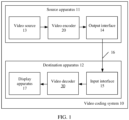
- FIG. 1 is a schematic block diagram of a video coding system 10 according to an embodiment of this application.
- the system 10 includes a source apparatus 11 and a destination apparatus 12.
- the source apparatus 11 generates encoded video data and sends the encoded video data to the destination apparatus 12.
- the destination apparatus 12 is configured to receive the encoded video data, decode the encoded video data, and display decoded video data.
- the source apparatus 11 and the destination apparatus 12 may include any one of a wide range of apparatuses, including a desktop computer, a laptop computer, a tablet computer, a set-top box, a mobile phone such as a so-called “smart” phone, a so-called “smart” touch panel, a television, a camera, a display apparatus, a digital media player, a video gaming console, a video streaming transmission apparatus, and the like.
- the destination apparatus 12 may receive to-be-decoded encoded video data via a link 16. Any kind of medium or apparatus capable of transmitting the encoded video data from the source apparatus 11 to the destination apparatus 12 may be included on the link 16. In a possible implementation, a communications medium enabling the source apparatus 11 to directly transmit the encoded video data to the destination apparatus 12 in real time may be included on the link 16.
- the encoded video data may be modulated according to a communications standard (for example, a wireless communication protocol) and transmitted to the destination apparatus 12.
- the communications medium may include any wireless or wired communications medium, for example, a radio spectrum or one or more physical transmission lines.
- the communications medium may constitute a part of a packet-based network (for example, a local area network, a wide area network, or a global network of the internet).
- the communications medium may include a router, a switch, a base station, or any other device for facilitating communication from the source apparatus 11 to the destination apparatus 12.
- the video coding system 10 further includes a storage apparatus.
- Encoded data may be output to the storage apparatus through an output interface 14.
- the encoded data may be accessed from the storage apparatus through an input interface 15.
- the storage apparatus may include any one of a variety of distributed or local data storage media, for example, a hard disk drive, a Blu-ray disc, a DVD, a CD-ROM, a flash memory, a volatile or non-volatile storage, or any other appropriate digital storage medium used for storing the encoded video data.
- the storage apparatus may correspond to a file server or another intermediate storage apparatus that is capable of keeping an encoded video generated by the source apparatus 11.
- the destination apparatus 12 may access the stored video data from the storage apparatus through streaming transmission or downloading.
- the file server may be any type of server capable of storing the encoded video data and transmitting the encoded video data to the destination apparatus 12.
- the file server includes a website server, a file transfer protocol server, a network-attached storage apparatus, or a local disk drive.
- the destination apparatus 12 may access the encoded video data through any standard data connection including an internet connection.
- the data connection may include a wireless channel (for example, a Wi-Fi connection), a wired connection (for example, a cable modem), or a combination thereof, that is suitable for accessing the encoded video data stored on the file server.
- Transmission of the encoded video data from the storage apparatus may be streaming transmission, downloading transmission, or a combination thereof.
- the technologies in this application are not necessarily limited to wireless applications or settings.
- the technologies may be applied to video coding, to support any one of a variety of multimedia applications, for example, over-the-air television broadcasting, cable television transmission, satellite television transmission, streaming video transmission (for example, through the internet), digital video coding for storage on a data storage medium, decoding of digital video stored on a data storage medium, or the like.
- the system 10 may be configured to support unidirectional or bidirectional video transmission, so as to support applications such as video streaming transmission, video playing, video broadcasting, and/or videotelephony.
- the source apparatus 11 may include a video source 13, a video encoder 20, and the output interface 14.
- the output interface 14 may include a modulator/demodulator (a modem) and/or a transmitter.
- the video source 13 may include, for example, the following source devices: a video capturing apparatus (for example, a video camera), an archive including a previously captured video, a video feed-in interface for receiving a video from a video content provider, and/or a computer graphics system for generating computer graphics data as a source video, or a combination thereof.
- the source apparatus 11 and the destination apparatus 12 may constitute a so-called camera phone or a video phone.
- the technologies described in this application may be applied to video coding, and may be applied to wireless and/or wired applications.
- the video encoder 20 may encode a video that is captured or pre-captured, or generated through calculation.
- the encoded video data may be directly transmitted to the destination apparatus 12 through the output interface 14 of the source apparatus 11.
- the encoded video data may also (or alternatively) be stored on the storage apparatus for subsequent access by the destination apparatus 12 or another apparatus for decoding and/or playing.
- the destination apparatus 12 includes the input interface 15, a video decoder 30, and a display apparatus 17.
- the input interface 15 may include a receiver and/or a modem.
- the input interface 15 of the destination apparatus 12 receives the encoded video data via the link 16.
- the encoded video data transmitted or provided to the storage apparatus via the link 16 may include a plurality of syntactic elements generated by the video encoder 20 for the video decoder 30 to decode video data. These syntax elements may be included in the encoded video data that is transmitted on the communications medium and that is stored in the storage medium or stored on the file server.
- the display apparatus 17 may be integrated with the destination apparatus 12 or disposed outside the destination apparatus 12.
- the destination apparatus 12 may include an integrated display apparatus and also be configured to connect to an interface of an external display apparatus.
- the destination apparatus 12 may be a display apparatus.
- the display apparatus 17 displays decoded video data to a user, and may include any of a variety of display apparatuses, for example, a liquid crystal display, a plasma display, an organic light-emitting diode display, or another type of display apparatus.
- the video encoder 20 and the video decoder 30 may operate according to, for example, a next-generation video coding compression standard (H.266) that is currently being developed, and may comply with an H.266 test model (JEM).
- the video encoder 20 and the video decoder 30 may operate according to, for example, other dedicated or industrial standards or their extensions of the ITU-T H.265 standard or the ITU-T H.264 standard, where the ITU-T H.265 standard is also referred to as a high efficiency video coding standard.
- the ITU-T H.264 standard is also referred to as MPEG-4 Part 10, or advanced video coding (advanced video coding, AVC).
- the technologies of this application are not limited to any specific coding standard.
- Other possible implementations of the video compression standard include MPEG-2 and ITU-TH.263.
- the video encoder 20 and the video decoder 30 may be integrated with an audio encoder and an audio decoder, respectively, and may include an appropriate multiplexer-demultiplexer (MUX-DEMUX) unit or other hardware and software to encode both audio and video in a same data stream or separate data streams.
- MUX-DEMUX multiplexer-demultiplexer
- the MUX-DEMUX unit may comply with the ITU H.223 multiplexer protocol or another protocol such as the user datagram protocol (UDP).
- the video encoder 20 and the video decoder 30 each may be implemented as any one of a variety of appropriate encoder circuitry, for example, one or more microprocessors, digital signal processors (digital signal processing, DSP), application specific integrated circuits (application specific integrated circuit, ASIC), field-programmable gate arrays (field-programmable gate array, FPGA), discrete logic, software, hardware, firmware, or any combination thereof.
- DSP digital signal processors
- ASIC application specific integrated circuit
- FPGA field-programmable gate array
- an apparatus may store an instruction for the software into an appropriate non-transitory computer-readable medium, and execute the instruction in a form of hardware by using one or more processors, to implement the technologies in this application.
- the video encoder 20 and the video decoder 30 each may be included in one or more encoders or decoders, and any one of the one or more encoders or decoders may be integrated as a part of a combined encoder/decoder (CODEC) in a corresponding apparatus.
- CDEC combined encoder/decoder
- the JCT-VC has developed the H.265 (HEVC) standard.
- HEVC standardization is based on an evolved model of a video coding apparatus, and the model is referred to as an HEVC test model (HM).
- HM HEVC test model
- a latest H.265 standard document is available at http://www.itu.int/rec/T-REC-H.265.
- a latest version of the standard document is H.265 (12/16).
- the video coding apparatus has several additional capabilities compared with an existing algorithm of ITU-TH.264/AVC. For example, H.264 provides nine intra prediction coding modes, whereas the HM can provide up to 35 intra prediction coding modes.
- the JVET is committed to developing the H.266 standard.
- An H.266 standardization process is based on an evolved model of a video coding apparatus, and the model is referred to as an H.266 test model.
- H.266 algorithm descriptions are available at http://phenix.int-evry.fr/jvet, and latest algorithm descriptions are included in JVET-F1001-v2.
- reference software for the JEM test model is available at https://jvet.hhi.fraunhofer.de/svn/svn_HMJEMSoftware/.
- a video frame or picture may be split into a sequence of tree blocks including both luma and chroma samples or a sequence of largest coding units (largest coding unit, LCU) including both luma and chroma samples, where the LCU is also referred to as CTU.
- a tree block has a function similar to a macroblock in the H.264 standard.
- a slice includes several consecutive tree blocks in a decoding order.
- a video frame or picture may be partitioned into one or more slices. Each tree block can be split into coding units based on a quadtree.
- a tree block serving as a root node of the quadtree may be split into four child nodes, and each child node may serve as a parent node and be split into four other child nodes.
- a final non-splittable child node serving as a leaf node of the quadtree includes a decoding node, for example, a decoded video block.
- a maximum quantity of splittable times of a tree block and a minimum size of a decoding node may be defined.
- a coding unit includes a decoding node, a prediction unit (prediction unit, PU), and a transform unit (transform unit, TU) associated with the decoding node.
- a size of the CU corresponds to a size of the decoding node, and a shape of the CU needs to be square.
- the size of the CU may range from 8 ⁇ 8 pixels up to at most 64 ⁇ 64 pixels, or be a larger tree block size.
- Each CU may include one or more PUs and one or more TUs. For example, syntactic data associated with the CU may describe partitioning of one CU into one or more PUs.
- Partitioning patterns may vary when the CU is encoded in a skip or direct mode, encoded in an intra prediction mode, or encoded in an inter prediction mode.
- the PU obtained through partitioning may be in a non-square shape.
- the syntactic data associated with the CU may also describe partitioning of one CU into one or more TUs based on the quadtree.
- the TU may be in a square or non-square shape.
- the HEVC standard allows TU-based transform, and TUs may be different for different CUs.
- a size of a TU is usually set based on a size of a PU within a given CU defined for a partitioned LCU. However, this may not always be the case.
- the size of the TU is generally the same as or less than the size of the PU.
- a quadtree structure referred to as a "residual quadtree" (residual quadtree, RQT) may be used to split a residual sample corresponding to the CU into smaller units.
- a leaf node of the RQT may be referred to as a TU.
- a pixel difference associated with the TU may be transformed to generate a transform coefficient, and the transform coefficient may be quantized.
- the PU includes data related to a prediction process.
- the PU when the PU is encoded in an intra mode, the PU may include data describing the intra prediction mode of the PU.
- the PU when the PU is encoded in an inter mode, the PU may include data defining a motion vector of the PU.
- the data defining the motion vector of the PU may describe a horizontal component of the motion vector, a vertical component of the motion vector, a resolution (for example, quarter-pixel precision or one-eighth-pixel precision) of the motion vector, a reference picture to which the motion vector points, and/or a reference picture list (for example, a list 0, a list 1, or a list C) of the motion vector.
- a given CU including one or more PUs may also include one or more TUs.
- the video encoder 20 may calculate a residual value corresponding to the PU.
- the residual value includes a pixel difference, and the pixel difference may be transformed into a transform coefficient, the transform coefficient is quantized, and the TU is scanned, to generate serialized transform coefficients for entropy decoding.
- the term "picture block” is usually used to indicate a decoding node of a CU.
- the term "picture block” may also be used to indicate a tree block including a decoding node, a PU, and a TU.
- the tree block is an LCU or a CU.
- a video sequence usually includes a series of video frames or pictures.
- a group of pictures (group of picture, GOP) includes a series of video pictures, one video picture, or a plurality of video pictures.
- the GOP may include syntactic data in header information of the GOP, in header information of one or more of the pictures, or elsewhere, and the syntactic data describes a quantity of pictures included in the GOP.
- Each slice of a picture may include slice syntactic data describing a coding mode of the corresponding picture.
- the video encoder 20 usually performs an operation on a video block in a video slice, to encode video data.
- the video block may correspond to the decoding node in the CU.
- a size of the video block may be fixed or changeable, and may vary according to a specified coding standard.
- the HM supports prediction for a variety of PU sizes. Assuming that a size of a specific CU is 2N ⁇ 2N, the HM supports intra prediction for a PU size of 2N ⁇ 2N or N ⁇ N, and inter prediction for a symmetric PU size of 2N ⁇ 2N, 2N ⁇ N, N ⁇ 2N, or N ⁇ N. The HM also supports asymmetric partitioning for inter prediction for PU sizes of 2N ⁇ nU, 2N ⁇ nD, nL ⁇ 2N, and nR ⁇ 2N.
- the CU In asymmetric partitioning, the CU is not partitioned in one direction, and is partitioned into two parts in the other direction, where one part occupies 25% of the CU and the other part occupies 75% of the CU.
- the part occupying 25% of the CU is indicated by an indicator including "n” followed by "U (Up)”, “D (Down)", “L (Left)” or “R (Right)". Therefore, for example, "2N ⁇ nU” refers to a horizontally partitioned 2N ⁇ 2N CU, with a 2N ⁇ 0.5N PU at the top and a 2N ⁇ 1.5N PU at the bottom.
- N ⁇ N and “N multiplied by N” may be used interchangeably to indicate a pixel size of a picture block in a vertical dimension and a horizontal dimension, for example, 16 ⁇ 16 pixels or 16 multiplied by 16 pixels.
- an N ⁇ N block usually has N pixels in the vertical direction and N pixels in the horizontal direction, where N represents a non-negative integer. Pixels in a block may be arranged in rows and columns.
- a quantity of pixels in the horizontal direction and a quantity of pixels in the vertical direction may be not necessarily the same.
- a block may include N ⁇ M pixels, where M is not necessarily equal to N.
- the JEM model further improves a video picture coding structure.
- a block coding structure referred to as a "quadtree plus binary tree" (QTBT) is introduced.
- QTBT quadtree plus binary tree
- a CU may be in a square or rectangular shape.
- Quadtree split is first performed on a CTU, and binary tree split is further performed on a leaf node of the quadtree.
- a leaf node of a binary tree is referred to as a CU.
- a CU in the JEM cannot be further split during prediction and transform.
- a CU, a PU, and a TU in the JEM have a same block size.
- a maximum CTU size is 256 ⁇ 256 luma pixels.
- the video encoder may perform intra prediction to reduce spatial redundancy between pictures.
- a CU may have one or more prediction units PUs depending on stipulations of different video compression coding standards.
- a plurality of PUs may belong to a CU.
- a PU and a CU have a same size.
- a partition pattern of the CU is that the CU is not partitioned or the CU is partitioned into one PU, and the PU is uniformly used for description.
- the video encoder may signal intra prediction information for the PU to the video decoder.
- the video encoder 20 and/or the video decoder 30 may identify a so-called "most probable" intra prediction mode during intra prediction decoding.
- the video encoder 20 and/or the video decoder 30 may identify intra prediction modes of previously decoded blocks (blocks with determined intra prediction modes may also be referred to as "reference blocks") neighbouring to a current decoding block, and compare these intra prediction modes with an intra prediction mode of the current decoding block (which is referred to as a "current block"). Due to spatial or temporal proximity of neighboring blocks to the current block, there may be a comparatively high probability that intra modes of these reference blocks are the same as or similar to an intra mode of the current block. As described in more detail below, intra prediction modes of a plurality of reference blocks may be considered during identifying of an MPM.
- each intra prediction mode may have an associated intra prediction mode index (an index that is pre-assigned to each mode in the standard instead of temporarily assigned in a coding process), and the intra prediction mode index is used to identify the intra prediction mode as one of a plurality of probable intra prediction modes.
- the JEM standard can support up to 67 luma intra prediction modes, where an index value (for example, an index value used for looking up a table) is assigned to each luma intra prediction mode, and the index value may be used to identify the intra prediction mode.
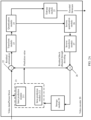
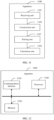
- FIG. 2A is a schematic block diagram of a video encoder 20 according to an embodiment of this application.
- the video encoder 20 may include a prediction module 21, a summator 22, a transform module 23, a quantization module 24, and an entropy coding module 25.
- the prediction module 21 may include an inter prediction module 211 and an intra prediction module 212.
- An internal structure of the prediction module 21 is not limited in this embodiment of this application.
- the video encoder 20 may further include an inverse quantization module 26, an inverse transform module 27, and a summator 28.
- the video encoder 20 may further include a storage module 29. It should be understood that the storage module 29 may alternatively be disposed outside the video encoder 20.
- the video encoder 20 may further include a filter (not shown in FIG. 2A ) to filter a boundary of a picture block, so as to remove an artifact from a reconstructed video picture.
- the filter usually filters an output of the summator 28.
- the video encoder 20 may further include a partitioning unit (not shown in FIG. 2A ).
- the video encoder 20 receives video data, and the partitioning unit partitions the video data into picture blocks.
- Such partitioning may further include partitioning into slices, picture blocks, or other larger units, and (for example) video block partitioning based on quadtree structures of an LCU and a CU.
- a slice may usually be split into a plurality of picture blocks (or may be split into a set of video blocks referred to as picture blocks).
- the prediction module 21 is configured to perform intra or inter prediction on a current coding picture block (a current block for short) to obtain a prediction value (which may be referred to as prediction information in this application) of the current block.
- the inter prediction module 211 included in the prediction module 21 performs inter prediction on the current block, to obtain an inter prediction value.
- the intra prediction module 212 performs intra prediction on the current block, to obtain an intra prediction value.
- the inter prediction module 211 needs to try a plurality of reference blocks in a reference picture for the current block.
- One or more specific reference blocks finally used for prediction is determined through rate-distortion optimization (rate-distortion optimization, RDO) or by using another method.
- the intra prediction module 212 may (for example) encode the current block by using various intra prediction modes during separate coding traversal.
- the intra prediction module 212 may calculate ratios of distortions to bit rates of various encoded blocks, to determine a specific intra prediction mode that presents a best rate-distortion value of the block. According to the JEM standard, there may be up to 67 intra prediction modes, and each intra prediction mode may be associated with an index.
- This application relates to, for example, intra decoding. Therefore, a particular technology in this application may be executed by the intra prediction module 212. In other feasible implementations, one or more other units of the video encoder 20 may additionally or alternatively be responsible for executing the technologies in this application.
- the intra prediction module 212 may determine an intra prediction mode of a current coding block (for example, according to a rate-distortion analysis as described above).
- the intra prediction module 212 may alternatively determine an intra prediction mode or intra prediction modes (referred to as an MPM or MPMs) of one or more previously decoded blocks neighbouring to a current intra decoding block.
- the intra prediction module 212 may (for example) compare the MPM with an intra mode of the current block, to indicate a determined intra mode of the current block based on a determined intra mode of a neighboring block, as described in more detail below.
- the video encoder 20 subtracts the prediction value from the current block, to form residual information.
- the transform module 23 is configured to transform the residual information.
- the transform module 23 transforms the residual information into a residual transform coefficient by performing, for example, discrete cosine transform (DCT) or conceptually similar transform (for example, discrete sine transform DST).
- the transform module 23 may send the obtained residual transform coefficient to the quantization module 24.
- the quantization module 24 quantizes the residual transform coefficient to further reduce a bit rate.
- the quantization module 24 may continue to scan a matrix including a quantized transform coefficient.
- the entropy coding module 25 may perform scanning.
- the entropy coding module 25 may perform entropy coding on a quantized residual transform coefficient to obtain a bitstream.
- the entropy coding module 25 may perform context-adaptive variable-length coding (CAVLC), context-based adaptive binary arithmetic coding (CABAC), syntax-based context-adaptive binary arithmetic coding (SBAC), probability interval partitioning entropy (PIPE) coding, or another entropy coding method or technology.
- CAVLC context-adaptive variable-length coding
- CABAC context-based adaptive binary arithmetic coding
- SBAC syntax-based context-adaptive binary arithmetic coding
- PIPE probability interval partitioning entropy
- an encoded bitstream may be transmitted to the video decoder 30, or stored for subsequent transmission or retrieval by the video decoder 30.
- the inverse quantization module 26 and the inverse transform module 27 perform inverse quantization and inverse transform, respectively, to reconstruct a residual block in a pixel domain as a reference block of the reference picture.
- the summator 28 adds residual information obtained through reconstruction and the prediction value generated by the prediction module 21, to generate a reconstructed block, and uses the reconstructed block as the reference block for storage in the storage module 29.
- the reference block may be used by the prediction module 21 to perform inter or intra prediction on a block in a subsequent video frame or picture.
- the video encoder 20 can be used to encode a video stream.
- the video encoder 20 may directly quantize the residual information without processing by the transform module 23 or processing by the inverse transform module 27.
- the video encoder 20 does not generate residual information, and correspondingly, processing by the transform module 23, processing by the quantization module 24, processing by the inverse quantization module 26, and processing by the inverse transform module 27 are not required.
- the video encoder 20 may directly store a reconstructed picture block as a reference block without processing by a filter unit.
- the quantization module 24 and the inverse quantization module 26 in the video encoder 20 may be combined together.
- the transform module 23 and the inverse transform module 27 in the video encoder 20 may be combined together.
- the summator 22 and the summator 28 may be combined together.
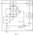
- FIG. 2B is a schematic block diagram of a video decoder 30 according to an embodiment of this application.
- the video decoder 30 may include an entropy decoding module 31, a prediction module 32, an inverse quantization module 34, an inverse transform module 35, and a reconstruction module 36.
- the prediction module 32 may include an inter prediction module 322 and an intra prediction module 321. This is not limited in this embodiment of this application.
- the video decoder 30 may further include a storage module 33. It should be understood that the storage module 33 may alternatively be disposed outside the video decoder 30. In some feasible implementations, the video decoder 30 may perform an example decoding process inverse to the encoding process described in the video encoder 20 in FIG. 2A .
- the video decoder 30 receives a bitstream from the video encoder 20.
- the entropy decoding module 31, the inverse quantization module 34, and the inverse transform module 35 successively perform entropy decoding, inverse quantization, and inverse transform respectively on the bitstream received by the video decoder 30, to obtain residual information. Then, whether intra prediction or inter prediction is performed for a current block is determined based on the bitstream. If intra prediction is performed, the intra prediction module 321 in the prediction module 32 constructs prediction information according to a used intra prediction method and by using pixel values of reference pixels of reconstructed blocks around the current block.
- the reconstruction module 36 can obtain reconstruction information by adding the prediction information and the residual information.
- this application relates to, for example, intra decoding. Therefore, a particular technology in this application may be executed by the intra prediction module 321. In other feasible implementations, one or more other units of the video decoder 30 may additionally or alternatively be responsible for executing the technologies in this application.
- the intra prediction module 321 may obtain, from the entropy decoding module 31, an index of a list of MPMs of a current block used to decode video data.
- the intra prediction module 321 may generate a list, to which the index belongs, by adding the MPM to the list in the same manner as the video encoder 20. Then, the intra prediction module 321 may determine, based on the obtained index, an appropriate intra mode of the current block used to decode the video data. In this manner, when the MPMs are not ordered based on intra mode index values (an index that is pre-assigned to each mode in a standard instead of temporarily assigned in a coding process) of the MPMs, the intra prediction module 321 may determine the appropriate MPM used for decoding the current block.
- intra mode index values an index that is pre-assigned to each mode in a standard instead of temporarily assigned in a coding process
- the video decoder may identify a so-called "most probable" intra prediction mode during intra prediction decoding.
- the video encoder for example, the video encoder 20
- intra prediction modes of a plurality of reference blocks may be considered during identifying of an MPM.
- FIG. 3 shows a feasible implementation of a current block ("current CU") and two reference blocks (for example, "A" and "B") that may be considered during intra decoding.
- a video encoder for example, the video encoder 20
- the video encoder 20 may assign a default intra mode, for example, a DC mode, to the block.
- a quantity of MPMs may be greater than 2.
- the video encoder 20 may generate an additional MPM based on intra modes of more than two reference blocks.
- the video encoder 20 may signal a 1-bit flag to indicate that the MPM is used to encode the current block (for example, the MPM flag is set to "1").
- the video encoder 20 may signal an index used to identify the MPM.
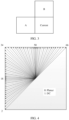
- FIG. 4 shows 67 intra modes supported in the JEM standard and an index value assigned to each of the intra modes.
- a planar mode has an original index value 0
- a direct current mode (DC mode) has an original index value 1
- directional prediction modes have original index values 2 to 66.
- the original index value refers to an index pre-assigned to each mode in a standard instead of temporarily assigned in a coding process.
- a reference pixel is mapped to a sample in a current block in a specific direction (which is marked by using an intra mode index) to obtain a prediction value of a current sample; or for each sample in the current block, a position of the sample is reversely mapped to a reference pixel in a specific direction (which is marked by using an intra mode index), and correspondingly, a pixel value of the reference pixel is a prediction value of a current sample.
- a difference from the directional prediction mode lies in that, in the DC mode, an average value of reference pixels is used as a prediction value of a pixel in a current block, while in the planar mode, a prediction value of a current sample is calculated based on pixel values of reference pixels on the above and left of the current sample and pixel values of reference samples on the upper-right side and the bottom-left side of the current sample.
- the picture blocks that are adjacent to the current block and whose intra prediction modes have been determined include a reconstructed block that is located in the same picture as the current block, for which a prediction value is obtained based on an intra prediction mode, and that is adjacent to the current block.
- a picture block adjacent to a bottom-left corner of the current block may be included; and on the above side of the current block, picture blocks adjacent to the top-left corner of the current block, and the bottom left, above right, and above left of the current block.
- the picture blocks in (1) may include picture blocks with an intra prediction mode on the left (L), above (A), the bottom left (BL), the above right (AR), and the above left (AL) of the current block shown in FIG. 5 .
- picture blocks that are in a picture in which a current block is located that are spatial non-adjacent to the current block, and whose intra prediction modes have been determined may be referred to as spatial non-adjacent picture blocks or picture blocks that are spatially non-adjacent to the current block.
- the picture in which the current block is located is divided into M groups of picture blocks that are not adjacent to the current block and whose intra prediction modes have been determined, each group of picture blocks that are not adjacent to the current block and whose intra prediction modes have been determined has a group number, and the current block has a width of w and a height of h.
- Picture blocks with a group number i include picture blocks in which pixel set basic units in the following coordinate positions in a virtual coordinate system are located: (-i ⁇ w,-i ⁇ h), (1+m ⁇ w,-i ⁇ h), (-m ⁇ w,-i ⁇ h), (-i ⁇ w,-m ⁇ h), and (-i ⁇ w,m ⁇ h+1), where m is an integer in a range from 0 to i - 1; M, i, w, and h are positive integers; i is not greater than M, and a value of i is not 1; and in the virtual coordinate system, a position, in the picture, of a pixel set basic unit at a bottom-right corner of the current block is used as an origin, a straight line on which the bottom boundary of the current block is located is used as a horizontal coordinate axis with a rightward direction as a positive horizontal direction, and a straight line on which the right boundary of the
- the picture blocks are picture blocks in a first circle (picture blocks in which a set of pixels marked 1 to 5 is located) neighboring to the current block; when the group number i is equal to 2, the picture blocks are picture blocks in a second circle (picture blocks in which a set of pixels marked 6 to 12 is located) that does not neighbor to the current block; when the group number i is equal to 3, the picture blocks are picture blocks in a third circle (picture blocks in which a set of pixels marked 13 to 27 is located) that does not neighbor to the current block.
- FIG. 6 is an example schematic diagram of the current block and picture blocks, associated with the current block, in non-adjacent positions according to an embodiment of this application.
- reconstruction of the plurality of spatial non-adjacent picture blocks is completed, in other words, intra prediction modes of the plurality of spatial non-adjacent picture blocks have been determined.
- intra prediction modes of the plurality of spatial non-adjacent picture blocks have been determined.
- the picture block may be excluded during a subsequent operation.
- the plurality of spatial non-adjacent picture blocks include picture blocks whose intra prediction modes have been determined and that are not adjacent to the current block, for example, picture blocks in which a set of pixels marked 6 to 27 in FIG. 6 are located.
- the picture blocks in which the set of pixels marked 1 to 5 in FIG. 6 are located are the spatially adjacent picture blocks described in (1).
- picture blocks in which a set of pixels marked 1 to 27 in FIG. 6 are located do not represent the PU or the CU described above.
- a large rectangular block marked C is the current block. It is assumed that small rectangles marked 1 to 27 are set as basic pixel units, and the large rectangle has the length of w basic pixel units and the height of h basic pixel units. w and h are both positive integers.
- a size of a picture block in which each small rectangle is located is the same as a size of the current block.
- the basic pixel unit may be a sample, may be a 4x4 pixel set, may be a 4x2 pixel set, or may be a pixel set of another size. This is not limited.
- a virtual coordinate system is created on a picture plane of the current block by using a position, in the picture, of a pixel set basic unit at a bottom-right corner of the current block as an origin, a straight line on which the bottom boundary of the current block is located as a horizontal coordinate axis with a rightward direction as a positive horizontal direction, a straight line on which the right boundary of the current block is located as a vertical coordinate axis with a downward direction as a positive vertical direction, coordinate positions of small rectangles marked 1 to 27 are (-w, 0), (0, -h), (1, -h), (-w, 1), (-w, -h), (-2 ⁇ w, 0), (0, -2 ⁇ h), (1, -2 ⁇ h), (-2 ⁇ w, 1), (-w, -2 ⁇ h), (-2 ⁇ w, -h), (-2 ⁇ w, h + 1), (w + 1, -2 ⁇ h), (-2 ⁇ w,
- FIG. 6 shows an example feasible implementation of the current block and the picture blocks that are in non-adjacent positions and that are associated with the current block in this embodiment of this application. There may be more than or less than 27 spatial neighboring picture blocks. This is not limited.
- the picture in which the current block is located may include at least two rows of coding tree units CTUs, and the size of the current block is not greater than a size of the coding tree unit.
- a length of a CTU is twice w
- a height of the CTU is twice h
- the current block C is located at the top-left corner of the CTU.
- a difference between a number of a row of the CTU in which picture blocks in which basic pixel units marked 27, 23, 19, 16, 17, 21, and 25 in FIG. 6 are located and whose intra prediction modes have been determined are located and a number of a row of the CTU in which the current block is located is 2.
- N picture blocks in which basic pixel units marked 27, 23, 19, 16, 17, 21, 25, and 26 are located are not spatial non-adjacent picture blocks.
- picture blocks in which basic pixel units marked 24, 20, 25, and 15 are located are spatial non-adjacent picture blocks.
- picture blocks in which basic pixel units marked 18, 22, and 26 are located are not spatial non-adjacent blocks, either.
- a picture block whose intra prediction mode has been determined and that neighbors to the current block in time domain is referred to as a temporal neighboring picture block, a picture block whose intra prediction mode has been determined and that temporally neighbors to the current block, or a picture block temporally neighboring to the current block.
- FIG. 7 is an example schematic diagram of the current block and a temporal neighboring picture block associated with the current block according to an embodiment of this application.
- FIG. 7 shows a spatial neighboring block at the bottom-right corner of a co-located block of the current block and a sub-block in the center of the current block.
- the sub-block is a basic unit for storing prediction information.
- the co-located block is a picture block, whose size, shape, and position are all the same as those of the current block, in a reference picture temporally neighboring to the picture in which the current block is located.
- T Ctr represents the sub-block in the center
- T Rb represents the spatial neighboring block at the bottom-right corner.
- the basic unit for storing the prediction information may be a 4x4 pixel set, may be a 4x8 pixel set, or may be a pixel set of another size. This is not limited.
- the prediction modes may be classified into a set of MPMs, a set of selected modes, and a set of non-selected modes (which may also be referred to as remaining modes), to improve efficiency of finally selecting an intra prediction mode for encoding.
- the set of MPMs includes six candidate intra prediction modes
- the set of selected modes includes 16 candidate intra prediction modes
- the remaining 45 candidate intra prediction modes are remaining modes, that is, belong to the set of non-selected modes.
- a set of candidate intra prediction modes in the set of MPMs is a subset of the 67 candidate intra prediction modes.
- candidate intra prediction modes in the set of MPMs are different from each other, and the candidate intra prediction modes in the set of selected modes are different from each other.
- a boundary pixel of an neighbouring reconstructed block around a current chroma block is also used as a reference pixel of the current block, the reference pixel is mapped to a sample in the current chroma block based on a specific prediction mode, and the sample is used as a prediction value of a pixel in the current chroma block.
- a difference lies in that because texture of the chroma component is usually simpler, a quantity of intra prediction modes of the chroma component is usually less than that of the luma component.
- chroma intra prediction modes there are 11 intra prediction modes for the chroma component, including five conventional chroma intra modes and six cross-component linear model (cross-component linear model, CCLM) modes.
- the chroma intra prediction modes may be classified into three types: a CCLM mode, a derived mode (derived mode, DM), and a chroma intra prediction mode that is obtained from a spatial neighboring block.
- a CCLM mode a chroma component prediction value of a pixel is calculated based on a correlation model by using a reconstructed value of a luma component of the pixel.
- a parameter of the correlation model is obtained through calculation based on reconstructed values of luma components and chroma components of reference pixels on the top and the left of the current block.
- the DM mode prediction is performed by using a luma component prediction mode of the current block as a chroma component prediction mode of the current block.
- the derived mode and the chroma intra prediction mode that is obtained from the spatial neighboring block may be collectively referred to as the set of conventional chroma intra modes.
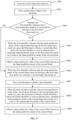
- FIG. 9 and FIG. 10 are flowcharts of video data decoding methods in one or more feasible implementations described in the embodiments of this application.
- FIG. 9 is a flowchart of a luma intra prediction method
- FIG. 10 is a flowchart of a chroma intra prediction method.
- the method in this embodiment of this application includes the following steps.
- the first luma intra mode set is a subset of a plurality of preset candidate luma prediction modes.
- the first luma intra mode set may be a set of MPMs.
- the first identifier is an identifier used to indicate whether a luma prediction mode, finally selected by an encoder side, of a current block is from the set of MPMs. For example, when the first identifier is "1", it indicates that the luma prediction mode of the current block is from the set of MPMs; and when the first identifier is "0", it indicates that the luma prediction mode of the current block does not belong to the set of MPMs.
- the first identifier may be MPM_flag.
- the set of MPMs may be constructed in a plurality of manners, including determining types of candidate luma prediction modes in the set of MPMs and an arrangement order of the candidate luma prediction modes in the set.
- the set of MPMs may include the following candidate luma prediction modes:
- the non-directional prediction mode in (D) includes a DC mode and/or a planar mode.
- the candidate luma prediction mode in (E) includes a candidate luma prediction mode represented by an index number whose difference from index number of the candidate luma prediction mode in (A) added to the set of MPMs is 1 (an absolute value of the index difference is 1).
- the candidate luma prediction mode in (E) may alternatively include candidate luma prediction mode represented by index number whose difference from index number of the candidate luma prediction mode in (A) added to the set of MPMs is 2, 3, or another integer. This is not limited.
- pruning in a process of adding different candidate luma prediction modes to the set of MPMs, "pruning" (pruning) needs to be performed, to avoid repeatedly adding a same candidate luma prediction mode to the set of MPMs, and ensure that each index value in the set of MPMs represents only one luma prediction mode.
- a capacity of the set of MPMs is preset, to be specific, a quantity of candidate luma prediction modes included in the set of MPMs does not exceed a first preset value.
- candidate luma prediction modes are sequentially added to the set of MPMs in a predetermined adding order until the first preset value is reached.
- candidate luma prediction modes in the set of MPMs include the candidate luma prediction modes in (A) to (F).
- a first possible adding order is: the candidate luma prediction modes in (A), the preset non-directional candidate luma prediction mode in (D), the candidate luma prediction modes in (C), the candidate luma prediction modes in (B), the candidate luma prediction modes in (E), and the default luma prediction modes in (F).
- the adding order in this application reflects only a trend, and specific implementation orders may be reversed or crossed. This is not limited.
- the candidate luma prediction modes in (A) and the preset non-directional candidate luma prediction mode in (D) may be added to the set of MPMs in the following order: a luma prediction mode of the picture block (L) on the left of the current block and neighbouring to the bottom-left corner of the current block, a luma prediction mode of the picture block (A) above the current block and neighbouring to the top-left corner of the current block, the planar mode, the DC mode, a luma prediction mode of the picture block (BL) neighbouring to the bottom-left corner of the current block, a luma prediction mode of the picture block (AR) neighbouring to the top-right corner of the current block, and a luma prediction mode of the picture block (AL) neighbouring to the top-left corner of the current block.
- a luma prediction mode of the picture block (L) on the left of the current block and neighbouring to the bottom-left corner of the current block a luma prediction mode of the picture block (A) above the current
- the candidate luma prediction modes in (C) may be added to the set of MPMs in the following order: a luma prediction mode of a sub-block in the center of a co-located block and a luma prediction mode of a spatial neighboring block at the bottom-right corner of the co-located block.
- the candidate luma prediction modes in (B) may be added to the set of MPMs in ascending order of group numbers of picture blocks whose intra prediction modes have been determined.
- the luma prediction modes of the spatial non-adjacent picture blocks are sequentially added to the set of MPMs in order of the first group, the second group, and the third group.
- luma prediction modes of the at least two picture blocks whose intra prediction modes have been determined and that are not adjacent to the current block may be sequentially added to the set of MPMs in ascending order of distances to an origin from the at least two picture blocks whose intra prediction modes have been determined and that are not adjacent to the current block.
- the distance is a sum of absolute values of a horizontal coordinate and a vertical coordinate, in a virtual coordinate system, of a pixel set basic unit in a preset position in the picture block whose intra prediction mode has been determined and that is not neighbouring to the current block.
- luma prediction modes of picture blocks whose intra prediction modes have been determined and that are not adjacent to the current block may be sequentially added to the set of MPMs in ascending order of distances to the origin from the picture blocks whose intra prediction modes have been determined and that are not adjacent to the current block.
- the distance is a sum of absolute values of a horizontal coordinate and a vertical coordinate, in the virtual coordinate system, of a pixel set basic unit in a preset position in the picture block whose intra prediction mode has been determined and that is not neighbouring to the current block.
- Obtaining motion information in the second group includes the following steps.
- luma prediction modes of picture blocks in the second group may be added in order of luma prediction modes of picture blocks in which basic pixel units marked 6, 7, 8, 9, 10, 11, 12, 13, and 14 are located.
- luma prediction modes of picture blocks in which basic pixel units marked 6, 7, 8, 9, 10, 11, 12, 13, 14, 15, 16, 17, 18, 19, 20, 21, 22, 23, 24, 25, 26, and 27 are located may be sequentially added to the set of MPMs in order of the picture blocks in which the basic pixel units marked 6 to 27 are located.
- an order of adding the candidate luma prediction modes in (B) may be a predetermined descending order of accuracy of performing prediction based on the luma prediction modes of all the spatially non-adjacent picture blocks.
- the prediction accuracy may be obtained through statistics collection within a historical duration.
- the luma prediction modes of the corresponding picture blocks are sequentially added to the set of MPMs in order of L->A->planar->DC->BL->AR->AL. If the set of MPMs is not fully filled, to be specific, the quantity of candidate luma prediction modes does not reach the first preset value, the luma prediction mode of the sub-block in the center of the co-located block and the luma prediction mode of the spatial neighboring picture block at the bottom-right corner of the co-located block are sequentially added to the set of MPMs.
- the luma prediction modes of the picture blocks marked 6 to 27 are sequentially added to the set of MPMs; if the set of MPMs is not fully filled yet, neighbouring directional prediction modes of the directional prediction modes in the current set of MPMs are sequentially added; and if the set of MPMs is not fully filled yet, the default luma prediction modes ⁇ planar, DC, VER (vertical mode), HOR (horizontal mode), luma prediction mode corresponding to the index 2, luma prediction mode corresponding to the index 34 ⁇ are sequentially added.
- a second possible adding order is: the candidate luma prediction modes in (A), the preset non-directional candidate luma prediction mode in (D), the candidate luma prediction modes in (B), the candidate luma prediction modes in (C), the candidate luma prediction modes in (E), and the default luma prediction modes in (F).
- a difference between the second possible adding order and the first possible adding order lies in that the adding order of the candidate luma prediction modes in (B) and the adding order of the candidate luma prediction modes(C) are reversed.
- the first possible adding order luma prediction modes of temporal neighboring picture blocks are preferentially added to the set of MPMs, and luma prediction modes of spatial non-adjacent picture blocks are added to the set of MPMs when the set of MPMs is not fully filled.
- luma prediction modes of spatial non-adjacent picture blocks are preferentially added to the set of MPMs, and luma prediction modes of temporal neighboring picture blocks are added to the set of MPMs when the set of MPMs is not fully filled.
- candidate luma prediction modes in the set of MPMs include the candidate luma prediction modes in (A), (B), (D), (E), and (F).
- a difference between the second possible implementation and the first possible implementation lies in that the luma prediction modes of the temporal neighboring picture blocks in (C) are not included in the second possible implementation.
- a third possible adding order is: the candidate luma prediction modes in (A), the preset non-directional candidate luma prediction mode in (D), the candidate luma prediction modes in (B), the candidate luma prediction modes in (E), and the default luma prediction modes in (F).
- the candidate luma prediction modes in (A) the preset non-directional candidate luma prediction mode in (D)
- the candidate luma prediction modes in (B) the candidate luma prediction modes in (E)
- F the default luma prediction modes in (F).
- the candidate luma prediction modes in the set of MPMs include the candidate luma prediction modes in (A), (C), (D), (E), and (F).
- a difference between the third possible implementation and the first possible implementation lies in that the luma prediction modes of the spatial non-adjacent picture blocks in (B) are not included in the third possible implementation.
- a fourth possible adding order is: the candidate luma prediction modes in (A), the preset non-directional candidate luma prediction mode in (D), the candidate luma prediction modes in (C), the candidate luma prediction modes in (E), and the default luma prediction modes in (F).
- the candidate luma prediction modes in (A) the preset non-directional candidate luma prediction mode in (D)
- the candidate luma prediction modes in (C) the candidate luma prediction modes in (E)
- F the default luma prediction modes in (F).
- S903. Determine whether the luma prediction mode, indicated by the first identifier, of the current block belongs to the first luma intra mode set. If the luma prediction mode, indicated by the first identifier, of the current block belongs to the first luma intra mode set, perform S904; or if the luma prediction mode, indicated by the first identifier, of the current block does not belong to the first luma intra mode set, perform S906.
- the candidate luma prediction mode indicated by the second identifier is used as the luma prediction mode of the current block.
- a unary code (Unary code) is used for the second identifier.
- a length of a codeword of the second identifier is shorter.
- Table 1 Luma prediction mode Codeword of a second identifier Index A 0 Index B 10 Planar 110 DC 1110 Index C 11110 Index D 11111
- the third identifier may be selected_flag.
- the second luma intra mode set may be a set of selected modes.
- the third identifier is a flag used to identify whether the luma prediction mode, finally selected by the encoder side, of the current block is from the set of selected modes. For example, when the third identifier is "1", it indicates that the intra prediction mode of the current block is from the set of selected modes; and when the third identifier is "0", it indicates that the intra prediction mode of the current block does not belong to the set of selected modes.
- the second luma intra mode set is a subset of the plurality of preset candidate luma prediction modes, and there is no intersection between the second luma intra mode set and the first luma intra mode set.
- candidate luma prediction modes in the set of selected modes include directional prediction modes that are obtained by sampling (B), (C), and (G) at a preset direction interval.
- the candidate luma intra prediction modes in the set of selected modes may include intra prediction modes that are not included in the set of MPMs and whose index numbers are ⁇ 0, 4, 8, 12 ... 60 ⁇ .
- the preset direction interval may be 4, or certainly may be another value, for example, 2 or 3.
- the candidate luma prediction mode needs to be selected from candidate luma prediction modes other than the candidate luma prediction modes included in the set of MPMs.
- a fifth possible adding order is: the candidate luma prediction modes in (C), the candidate luma prediction modes in (B), and the candidate luma prediction modes in (G).
- the candidate luma prediction modes in (C) and an order of the candidate luma prediction modes in (B) refer to the description in the first possible implementation. Details are not described herein again.
- a sixth possible adding order is: the candidate luma prediction modes in (B), the candidate luma prediction modes in (C), and the candidate luma prediction modes in (G).
- a difference between the sixth possible adding order and the fifth possible adding order lies in that the adding order of the candidate luma prediction modes in (B) and the adding order of the candidate luma prediction modes in (C) are reversed.
- the luma prediction modes (C) of the temporal neighboring picture blocks are preferentially added to the set of selected modes, and the luma prediction modes (B) of the spatial non-adjacent picture blocks are added to the set of selected modes when the set of selected modes is not fully filled.
- the luma prediction modes (B) of the spatial non-adjacent picture blocks are preferentially added to the set of selected modes, and the luma prediction modes (C) of the temporal neighboring picture blocks are added to the set of selected modes when the set of MPMs is not fully filled.
- candidate luma prediction modes in the set of selected modes include the candidate luma prediction modes in (C) and the directional prediction modes in (G) that are obtained by performing sampling at a preset direction interval.
- a difference between the fifth possible implementation and the fourth possible implementation lies in that the luma prediction modes of the spatial non-adjacent picture blocks in (B) are not included in the fifth possible implementation.
- a seventh possible adding order is: the candidate luma prediction modes in (C) and the candidate luma prediction modes in (G).
- candidate luma prediction modes in the set of selected modes include the candidate luma prediction modes in (B) and the directional prediction modes in (G) that are obtained by performing sampling at a preset direction interval.
- a difference between the fifth possible implementation and the fourth possible implementation lies in that the luma prediction modes of the spatial non-adjacent picture blocks in (C) are not included in the fifth possible implementation.
- an eighth possible adding order is: the candidate luma prediction modes in (B) and the candidate luma prediction modes in (G).
- candidate luma prediction modes in the set of MPMs do not include the candidate luma prediction modes in (B) and/or the candidate luma prediction modes in (C), and candidate luma prediction modes in the set of selected modes include the candidate luma prediction modes in (B) and/or the candidate luma prediction modes in (C).
- candidate luma prediction modes in the set of MPMs include the candidate luma prediction modes in (B) and/or the candidate luma prediction modes in (C), and candidate luma prediction modes in the set of selected modes do not include the candidate luma prediction modes in (B) and/or the candidate luma prediction modes in (C).
- the fourth to the eighth possible implementations provide, as examples, several independent implementations of constructing the set of selected modes.
- the set of selected modes may be constructed in combination with an implementation method in another possible implementation.
- An independent implementation is not limited thereto, and a manner of combining different implementations is not limited.
- the third identifier indicates that the luma prediction mode of the current block belongs to the second luma intra mode set
- the fourth identifier may be selected mode_flag. That is, the candidate luma prediction mode indicated by the fourth identifier is used as the luma prediction mode of the current block.
- a fixed-length code (fixed-length code) is used for the fourth identifier. Specifically, when there are 16 candidate luma prediction modes in the set of selected modes, each candidate luma prediction mode in the set of selected modes is coded by using a 4-bit fixed-length codeword.
- the bitstream is parsed to obtain a fifth identifier.
- the fifth identifier is used to indicate a candidate luma prediction mode, used as the luma prediction mode of the current block, in candidate luma prediction modes in the plurality of preset candidate luma prediction modes other than the first luma intra mode set and the second luma intra mode set.
- the candidate luma prediction mode indicated by the fifth identifier is used as the luma prediction mode of the current block.
- the candidate luma prediction modes in the plurality of preset candidate luma prediction modes other than the first luma intra mode set and the second luma intra mode set are referred to as candidate luma prediction modes in a set of non-selected modes in some embodiments, and are referred to as remaining candidate luma prediction modes (remaining modes) in some other embodiments. This is not limited.
- a truncated binary code (truncated binary code) is used for the fifth identifier.
- a set of 67 preset candidate luma prediction modes is classified into six candidate luma prediction modes belonging to the set of MPMs, 16 candidate luma prediction modes belonging to the set of selected modes, and remaining candidate luma prediction modes belonging to the set of non-selected modes. The following steps are performed.
- MPM_flag 1001.
- MPM_flag 1
- MPM mode_flag an MPM mode index
- a decoding mode based on a unary code is used for the MPM mode index.
- a process of constructing the list of MPMs is as follows (referring to a position relationship between blocks in FIG. 6 ). The following order is merely an example, and is not specifically limited.
- step 8 may alternatively be replaced in the following manner: If there are less than six prediction modes in the list of MPMs, the luma prediction modes of the picture blocks marked 6 to 27 in FIG. 6 , the luma prediction mode of the sub-block in the center of the co-located block in FIG. 7 or FIG. 8 , and the luma prediction mode of the spatial neighboring block at the bottom-right corner of the co-located block in FIG. 7 or FIG. 8 are sequentially added to the list of MPMs, and it is ensured that a to-be-added luma prediction mode does not exist in the list of MPMs; and if a quantity of modes in the list of MPMs is up to 6, the adding stops.
- angle_mode1 and angle_mode+1 are neighbouring angle prediction modes, that is, angle_mode1 and angle_mode+1, of an angle prediction mode (a mode angle_mode other than the planar mode and the DC mode) in the list of MPMs to the list of MPMs in order of modes that have been added to the existing list of MPMs.
- angle_mode-1 corresponds to an adding mode 66
- angle_mode+1 corresponds to an adding mode 2.
- the angle prediction mode may be referred to as a directional prediction mode.
- MPM_flag decode selected_flag. If selected_flag is 1, it indicates that a prediction mode currently selected for decoding is a selected mode; and obtain an index of the selected mode (selected mode_flag) through decoding, and then derive the luma prediction mode based on a constructed list of selected modes, where a decoding mode based on a 4-bit fixed-length code is used for the index of the selected mode, and a process of constructing the list of selected modes is as follows:
- step 1 may alternatively be replaced in the following manner:
- the luma prediction modes of the picture blocks marked 6 to 27 in FIG. 6 , the luma prediction mode of the sub-block in the center of the co-located block in FIG. 7 or FIG. 8 , and the luma prediction mode of the spatial neighboring block at the bottom-right corner of the co-located block are sequentially added to the list of selected modes, and it is ensured that a to-be-added luma prediction mode exists in neither the list of selected modes nor the list of MPMs; and if a quantity of modes in the list of selected modes is up to 16, the adding stops.
- An angle interval is a multiple of 2. For example, if an angle interval for first adding is 2, the neighbouring angle prediction modes are angle_mode-2 and angle_mode+2. If there are still less than 16 selected modes in the set of selected modes after all angle modes in the list of MPMs are traversed, neighbouring angle modes with an angle interval of 4 continue to be added. By analogy, an angle interval is gradually increased until 16 modes are selected. In the adding process, it needs to be ensured that a to-be-added angle mode is not added and is not a mode in the list of MPMs.
- neighbouring angles of an angle mode circulate based on 65 modes, that is, a mode 2 and a mode 66 are neighbouring angle modes.
- the angle interval may alternatively be a multiple of 1, a multiple of 3, or the like. This is not limited, provided that the angle interval is consistent with that agreed on by the encoder side in advance in a protocol.
- selected_flag indicates that a luma prediction mode currently selected for decoding is a mode in the list of non-selected modes; and obtain a mode index through decoding, and derive a prediction mode, where an index of the non-selected mode may be represented by a truncated binary code (truncated binary code).
- the set of conventional chroma intra modes may include candidate chroma prediction modes:
- the non-directional prediction mode (K) includes a DC mode and/or a planar mode.
- the candidate chroma prediction mode in (L) includes a candidate chroma prediction mode represented by an index number whose difference from index number of the candidate chroma prediction mode in (H) added to the set of MPMs is 1 (an absolute value of the index difference is 1).
- the candidate chroma prediction mode in (L) may alternatively include candidate chroma prediction mode represented by index number whose difference from index number of the candidate chroma prediction mode in (H) added to the set of MPMs is 2, 3, or another integer. This is not limited.
- pruning in a process of adding different candidate chroma prediction modes to the set of conventional chroma intra modes, "pruning" (pruning) needs to be performed, to avoid repeatedly adding a same candidate chroma prediction mode to the set of conventional chroma intra modes, and ensure that each index value in the set of conventional chroma intra modes represents only one chroma prediction mode.
- a capacity of the set of conventional chroma intra modes is preset, to be specific, a quantity of candidate chroma prediction modes included in the set of conventional chroma intra modes does not exceed a first preset value.
- candidate chroma prediction modes are sequentially added to the set of conventional chroma intra modes in a predetermined adding order until a third preset value is reached.
- a ninth possible adding order is: the candidate chroma prediction modes in (N), the candidate chroma prediction modes in (H), the candidate chroma prediction modes in (J), the candidate chroma prediction modes in (I), the candidate chroma prediction modes in (K), the candidate chroma prediction modes in (L), and the default chroma prediction modes in (M).
- the adding order in this application reflects only a trend, and specific implementation orders may be reversed or crossed. This is not limited.
- chroma prediction modes of the at least two picture blocks whose intra prediction modes have been determined and that are not adjacent to the current block may be sequentially added to the set of conventional chroma intra modes in ascending order of distances to an origin from the at least two picture blocks whose intra prediction modes have been determined and that are not adjacent to the current block.
- the distance is a sum of absolute values of a horizontal coordinate and a vertical coordinate, in a virtual coordinate system, of a pixel set basic unit in a preset position in the picture block whose intra prediction mode has been determined and that is not neighbouring to the current block.
- a chroma prediction mode of a picture block in which a basic pixel unit closer to the preset basic pixel unit is located is added preferentially.
- chroma prediction modes of picture blocks in the second group may be added in order of chroma prediction modes of picture blocks in which basic pixel units marked 6, 7, 8, 9, 10, 11, 12, 13, and 14 are located.
- chroma prediction modes of picture blocks in which basic pixel units marked 6, 7, 8, 9, 10, 11, 12, 13, 14, 15, 16, 17, 18, 19, 20, 21, 22, 23, 24, 25, 26, and 27 are located may be sequentially added to the set of conventional chroma intra modes in order of the picture blocks in which the basic pixel units marked 6 to 27 are located.
- the chroma prediction modes of the corresponding picture blocks are sequentially added to the set of conventional chroma intra modes in order of L->A->BL->AR->AL. If the set of conventional chroma intra modes is not fully filled, to be specific, the quantity of candidate chroma prediction modes does not reach the third preset value, the chroma prediction mode of the sub-block in the center of the co-located block and the chroma prediction mode of the spatial neighboring picture block at the bottom-right corner of the co-located block are sequentially added to the set of conventional chroma intra modes.
- the chroma prediction modes of the picture blocks marked 6 to 27 are sequentially added to the set of conventional chroma intra modes; if the set of conventional chroma intra modes is not fully filled yet, the planar mode and the DC mode are sequentially added to the set of conventional chroma intra modes; if the set of conventional chroma intra modes is not fully filled yet, neighbouring directional prediction modes of the directional prediction modes in the current set of conventional chroma intra modes are sequentially added; and if the set of conventional chroma intra modes is not fully filled yet, the default chroma prediction modes ⁇ VER (vertical mode), HOR (horizontal mode), chroma prediction mode corresponding to the index 2 ⁇ are sequentially added.
- the default chroma prediction modes ⁇ VER (vertical mode), HOR (horizontal mode), chroma prediction mode corresponding to the index 2 ⁇ are sequentially added.
- a tenth possible adding order is: the candidate chroma prediction modes in (N), the candidate chroma prediction modes in (H), the candidate chroma prediction modes in (I), the candidate chroma prediction modes in (J), the candidate chroma prediction modes in (K), the candidate chroma prediction modes in (L), and the default chroma prediction modes in (M).
- a difference between the tenth possible adding order and the ninth possible adding order is that the adding order of the candidate chroma prediction modes in (I) and the adding order of the candidate chroma prediction modes in (J) are reversed.
- chroma prediction modes of temporal neighboring picture blocks are preferentially added to the set of conventional chroma intra modes; and chroma prediction modes of spatial non-adjacent picture blocks are added to the set of conventional chroma intra modes when the set of conventional chroma intra modes is not fully filled.
- chroma prediction modes of spatial non-adjacent picture blocks are preferentially added to the set of conventional chroma intra modes, and chroma prediction modes of temporal neighboring picture blocks are added to the set of conventional chroma intra modes when the set of conventional chroma intra modes is not fully filled.
- the candidate chroma prediction modes in the set of conventional chroma intra modes include the candidate chroma prediction modes in (N), (H), (I), (K), (L), and (M).
- a difference between the tenth possible implementation and the ninth possible implementation lies in that the chroma prediction modes of the temporal neighboring picture blocks in (J) are not included in the tenth possible implementation. For repeated content between the tenth possible implementation and the ninth possible implementation, details are not described herein again.
- an eleventh possible adding order includes: the candidate chroma prediction modes in (N), the candidate chroma prediction modes in (H), the candidate chroma prediction modes in (I), the candidate chroma prediction mode in (K), the candidate chroma prediction modes in (L), and the default chroma prediction modes in (M).
- N the candidate chroma prediction modes in
- H the candidate chroma prediction modes in
- I the candidate chroma prediction mode in
- K candidate chroma prediction mode in
- L the default chroma prediction modes in
- M default chroma prediction modes in
- the candidate chroma prediction modes in the set of conventional chroma intra modes include the candidate chroma prediction modes in (N), (H), (J), (K), (L), and (M).
- a difference between the eleventh possible implementation and the ninth possible implementation lies in that the chroma prediction modes of the spatial non-adjacent picture blocks in (I) are not included in the eleventh possible implementation.
- a twelfth possible adding order is: the candidate chroma prediction modes in (N), the candidate chroma prediction modes in (H), the candidate chroma prediction modes in (J), the candidate chroma prediction modes in (K), the candidate chroma prediction modes in (L), and the default chroma prediction modes in (M).
- the fourth to the sixth possible implementations of constructing the set of selected modes, the first to the third possible implementations of constructing the set of MPMs, and the ninth to the eleventh possible implementations of constructing the set of conventional chroma intra modes may be combined in any manner. This is not limited.
- 11 preset candidate chroma prediction modes are classified into five conventional chroma intra prediction modes and six CCLM modes, and the following step is performed:
- a flag is obtained through decoding. If the flag is 0, it indicates that the chroma prediction mode of the current block is not a CCLM mode, but is a conventional chroma intra mode.
- the chroma prediction mode is derived based on an index (flag) through decoding and a list of conventional chroma intra modes.
- a process of constructing the list of conventional chroma intra modes is as follows (referring to a position relationship between blocks in FIG. 6 ). The following order is merely an example, and is not specifically limited.
- step 7 may alternatively be replaced in the following manner: If there are less than five prediction modes in the List of conventional chroma intra modes, the chroma prediction modes of the picture blocks marked 6 to 27 in FIG. 6 , the chroma prediction mode of the sub-block in the center of the co-located block in FIG. 7 or FIG. 8 , and the chroma prediction mode of the spatial neighboring block at the bottom-right corner of the co-located block in FIG. 7 or FIG.
- angle_mode-1 and angle_mode+1 are neighbouring angle prediction modes, that is, angle_mode-1 and angle_mode+1, of an angle prediction mode (a mode angle_mode other than the planar mode and the DC mode) modes to the list of conventional chroma intra modes in order of modes that have been added to the list of conventional chroma intra modes.
- angle_mode-1 corresponds to an adding mode 66
- angle_mode+1 corresponds to an adding mode 2. If the quantity of modes in the list of conventional chroma intra modes is up to 5, the adding stops.
- an embodiment of this application further provides an apparatus 1100.
- the apparatus 1100 may be specifically a processor, a chip, or a chip system in a video encoder, or a module in a video encoder, for example, an intra prediction module 212; or may be a processor, a chip, or a chip system in a video decoder, or a module in a video decoder, for example, an intra prediction module 321.
- the apparatus may include a receiving unit 1101, a construction unit 1102, a parsing unit 1103, and a calculation unit 1104.
- the receiving unit 1101, the construction unit 1102, the parsing unit 1103, and the calculation unit 1104 are configured to perform the steps in the methods in the embodiments corresponding to FIG. 9 and FIG. 10 .
- the receiving unit 1101 may be configured to receive a bitstream;
- the construction unit 1102 is configured to construct a first luma intra mode set, a second luma intra mode set, and a chroma intra mode set;
- the parsing unit 1103 is configured to parse the bitstream to obtain an identifier, for example, parse the bitstream to obtain a first identifier to a seventh identifier.
- the calculation unit 1104 is configured to obtain a luma prediction value and a chroma prediction value.
- the apparatus 1200 may include a communications interface 1210 and a processor 1220.
- the apparatus 1200 may further include a memory 1230.
- the memory 1230 may be disposed inside the apparatus, or may be disposed outside the apparatus.
- the receiving unit 1101, the construction unit 1102, the parsing unit 1103, and the calculation unit 1104 that are shown in FIG. 11 may all be implemented by the processor 1220.
- the processor 1220 sends or receives a video stream or a bitstream through the communications interface 1210, and is configured to implement the methods in FIG. 9 and FIG. 10 .
- steps in a processing procedure may be implemented by using an integrated logic circuit of hardware in the processor 1220 or an instruction in a form of software, to complete the methods in FIG. 9 and FIG. 10 .
- the communications interface 1210 in this embodiment of this application may be a circuit, a bus, a transceiver, or any other apparatus that can be configured to exchange information.
- the another apparatus may be a device connected to the apparatus 1200.
- the apparatus when the apparatus is a video encoder, the another apparatus may be a video decoder.
- the processor 1220 may be a general purpose processor, a digital signal processor, an application-specific integrated circuit, a field programmable gate array or another programmable logic device, a discrete gate or transistor logic device, or a discrete hardware component, and may implement or execute the methods, steps, and logical block diagrams disclosed in the embodiments of this application.
- the general purpose processor may be a microprocessor, any conventional processor, or the like.
- the steps in the methods disclosed with reference to the embodiments of this application may be directly performed by a hardware processor, or may be performed by using a combination of hardware in the processor and a software unit.
- Program code executed by the processor 1220 to implement the foregoing methods may be stored in the memory 1230.
- the memory 1230 is coupled to the processor 1220.
- the coupling in this embodiment of this application is an indirect coupling or a communication connection between apparatuses, units, or modules, may be in an electrical form, a mechanical form, or another form, and is used for information exchange between the apparatuses, the units, or the modules.
- the processor 1220 may operate with the memory 1230.
- the memory 1230 may be a nonvolatile memory such as a hard disk drive (hard disk drive, HDD) or a solid-state drive (solid-state drive, SSD); or may be a volatile memory (volatile memory) such as a random-access memory (random-access memory, RAM).
- the memory 1230 is any other medium that can be configured to carry or store desirable program code that has an instruction or a data structure form and that can be accessed by a computer, but is not limited thereto.
- This embodiment of this application does not limit a specific connection medium between the communications interface 1210, the processor 1220, and the memory 1230.
- the memory 1230, the processor 1220, and the communications interface 1210 are connected through a bus.
- the bus is represented by a thick line in FIG. 12 , and a connection mode between other parts is merely an example for description, and imposes no limitation.
- the bus may be classified into an address bus, a data bus, a control bus, and the like. For ease of representation, only one thick line is used to represent the bus in FIG. 12 , but this does not mean that there is only one bus or only one type of bus.
- an embodiment of this application further provides a computer storage medium.
- the storage medium stores a software program, and the software program is read and executed by one or more processors, to implement the method provided in any one or more of the foregoing embodiments.
- the computer readable storage medium may include: any medium that can store program code, such as a USB flash drive, a removable hard disk, a read-only memory, a random-access memory, a magnetic disk, or an optical disc.
Landscapes
- Engineering & Computer Science (AREA)
- Multimedia (AREA)
- Signal Processing (AREA)
- Compression Or Coding Systems Of Tv Signals (AREA)
Claims (12)
- Verfahren zur Intra-Prädiktion eines Bildblocks, umfassend:Erstellen (S901) eines ersten Luma-Intra-Modus-Satzes für einen aktuellen Block, wobei der erste Luma-Intra-Modus-Satz ein Teilsatz einer Vielzahl von voreingestellten Kandidaten-Luma-Prädiktionsmodi und ein Satz der wahrscheinlichsten Intra-Prädiktionsmodi ist; und der erste Luma-Intra-Modus-Satz einen bestimmten Luma-Prädiktionsmodus eines Bildblocks umfasst, der in einem Bild, in dem sich der aktuelle Block befindet, räumlich nicht zu dem aktuellen Block benachbart ist;Parsen (S902) eines empfangenen Bitstroms, um eine erste Kennung zu erlangen;Parsen (S904) des Bitstroms, um eine zweite Kennung zu erlangen, wenn die erste Kennung angibt, dass ein Luma-Prädiktionsmodus des aktuellen Blocks zu dem ersten Luma-Intra-Modus-Satz gehört, wobei die zweite Kennung verwendet wird, um anzugeben, welcher Kandidaten-Luma-Prädiktionsmodus in dem ersten Luma-Intra-Modus-Satz als Luma-Prädiktionsmodus des aktuellen Blocks verwendet wird; undErlangen (S905) eines Luma-Prädiktionswerts des aktuellen Blocks auf Grundlage des Luma-Prädiktionsmodus des aktuellen Blocks;dadurch gekennzeichnet, dassder aktuelle Block eine Breite von w Pixelsatz-Grundeinheiten und eine Höhe von h Pixelsatz-Grundeinheiten aufweist, das Bild, in dem sich der aktuelle Block befindet, M Gruppen von Bildblöcken umfasst, die räumlich nicht zu dem aktuellen Block benachbart sind, und jede Gruppe von Bildblöcken, die räumlich nicht zu dem aktuellen Block benachbart sind, eine Gruppennummer aufweist, wobei ein Bildblock mit einer Gruppennummer i Bildblöcke umfasst, in denen sich Pixelsatz-Grundeinheiten an den folgenden Koordinatenpositionen in einem virtuellen Koordinatensystem befinden: (-i×w, -i×h), (1+m×w, -i×h), (-m×w, -i×h), (-i×w, -m×h) und (-i×w, m×h+1), wobei m eine ganze Zahl in einem Bereich von 0 bis i-1 ist; M, i, w und h positive ganze Zahlen sind; i nicht größer als M ist und ein Wert von i ungleich 1 ist; und in dem virtuellen Koordinatensystem eine Position einer Pixelsatz-Grundeinheit in dem Bild in der unteren rechten Ecke des aktuellen Blocks als Ursprung verwendet wird, eine gerade Linie, auf der sich die untere Grenze des aktuellen Blocks befindet, als horizontale Koordinatenachse mit einer Richtung nach rechts als positive horizontale Richtung verwendet wird und eine gerade Linie, auf der sich die rechte Grenze des aktuellen Blocks befindet, als vertikale Koordinatenachse mit einer Richtung nach unten als positive vertikale Richtung verwendet wird.
- Verfahren nach Anspruch 1, wobei das Bild, in dem sich der aktuelle Block befindet, mindestens zwei Reihen von Kodierungsbaumeinheiten, CTUs, beinhaltet und eine Größe des aktuellen Blocks nicht größer ist als eine Größe einer Kodierungsbaumeinheit, in der sich der aktuelle Block befindet; und eine Differenz in dem Bild zwischen einer Nummer einer Reihe der Kodierungsbaumeinheit in dem Bild, in der sich der aktuelle Block befindet, und einer Nummer einer Reihe einer Kodierungsbaumeinheit in dem Bild, in der sich der Bildblock befindet, der nicht räumlich benachbart zu dem aktuellen Block ist, kleiner als N ist, wobei N eine ganze Zahl größer als 1 ist.
- Verfahren nach Anspruch 1 oder 2, wobei der erste Luma-Intra-Modus-Satz ferner einen bestimmten Luma-Prädiktionsmodus eines Bildblocks in einem Referenzbild umfasst, das zeitlich an das Bild angrenzt, in dem sich der aktuelle Block befindet, wobei das Erstellen des ersten Luma-Intra-Modus-Satzes Folgendes umfasst:Erstellen des ersten Luma-Intra-Modus-Satzes auf Grundlage eines bestimmten Luma-Prädiktionsmodus und eines ungerichteten Prädiktionsmodus eines Bildblocks, der an den aktuellen Block angrenzt, wobei eine Anzahl von Kandidaten-Luma-Prädiktionsmodi, die in dem ersten Luma-Intra-Modus-Satz enthalten sind, einen voreingestellten Wert nicht erreicht; undsequenzielles Hinzufügen eines Luma-Prädiktionsmodus eines Teilblocks im Zentrum eines kolokalisierten Blocks und eines Luma-Prädiktionsmodus eines räumlich angrenzenden Blocks in der unteren rechten Ecke des kolokalisierten Blocks zu dem ersten Luma-Intra-Modus-Satz, bis die Menge der in dem ersten Luma-Intra-Modus-Satz enthaltenen Kandidaten-Luma-Prädiktionsmodi den voreingestellten Wert erreicht, wobei der Teilblock eine Grundeinheit zum Speichern von Prädiktionsinformationen ist; der kolokalisierte Block in einem Referenzbild, das zeitlich an das Bild angrenzt, in dem sich der aktuelle Block befindet, ein Bildblock ist, dessen Größe, Form und Position alle dieselben sind wie diejenigen des aktuellen Blocks; und sich die in dem ersten Luma-Intra-Modus-Satz enthaltenen Kandidaten-Luma-Prädiktionsmodi voneinander unterscheiden.
- Verfahren nach Anspruch 3, wobei, nachdem der Luma-Prädiktionsmodus des Teilblocks im Zentrum des kolokalisierten Blocks und der Luma-Prädiktionsmodus des räumlich angrenzenden Blocks in der unteren rechten Ecke des kolokalisierten Blocks sequenziell zu dem ersten Luma-Intra-Modus-Satz hinzugefügt wurde, die Menge der in dem ersten Luma-Intra-Modus-Satz enthaltenen Kandidaten-Luma-Prädiktionsmodi den voreingestellten Wert nicht erreicht, das Verfahren ferner Folgendes umfasst:
sequenzielles Hinzufügen von bestimmten Luma-Prädiktionsmodi von Bildblöcken, die räumlich nicht benachbart zu dem aktuellen Block sind, zu dem ersten Luma-Intra-Modus-Satz in aufsteigender Reihenfolge der Gruppennummern, bis die Anzahl der Kandidaten-Luma-Prädiktionsmodi in dem ersten Luma-Intra-Modus-Satz den voreingestellten Wert erreicht, wobei sich die Kandidaten-Luma-Prädiktionsmodi in dem ersten Luma-Intra-Modus-Satz voneinander unterscheiden. - Verfahren nach Anspruch 3, wobei, nachdem der Luma-Prädiktionsmodus des Teilblocks im Zentrum des kolokalisierten Blocks und der Luma-Prädiktionsmodus des räumlich angrenzenden Blocks in der unteren rechten Ecke des kolokalisierten Blocks sequenziell zu dem ersten Luma-Intra-Modus-Satz hinzugefügt wurde, die Menge der in dem ersten Luma-Intra-Modus-Satz enthaltenen Kandidaten-Luma-Prädiktionsmodi den voreingestellten Wert nicht erreicht, das Verfahren ferner Folgendes umfasst:
sequenzielles Hinzufügen von bestimmten Luma-Prädiktionsmodi der Bildblöcke, die räumlich nicht zu dem aktuellen Block benachbart sind, zu dem ersten Luma-Intra-Modus-Satz in aufsteigender Reihenfolge von Entfernungen zu einem Ursprung von Bildblöcken, die räumlich nicht zu dem aktuellen Block benachbart sind, wobei die Entfernung eine Summe von Absolutwerten einer horizontalen Koordinate und einer vertikalen Koordinate einer Pixelsatz-Grundeinheit in einem virtuellen Koordinatensystem an einer voreingestellten Position in dem Bildblock ist, der räumlich nicht zu dem aktuellen Block benachbart ist. - Verfahren nach Anspruch 4 oder 5, wobei das sequentielle Hinzufügen der bestimmten Luma-Prädiktionsmodi der Bildblöcke, die räumlich nicht zu dem aktuellen Block benachbart sind, zu dem ersten Luma-Intra-Modus-Satz Folgendes umfasst:
sequenzielles Hinzufügen der bestimmten Luma-Prädiktionsmodi der Bildblöcke, die räumlich nicht zu dem aktuellen Block benachbart sind, zu dem ersten Luma-Intra-Modus-Satz in der Reihenfolge der Bildblöcke, in denen sich Pixelsatz-Grundeinheiten in den folgenden Koordinatenpositionen in dem virtuellen Koordinatensystem befinden, bis die Anzahl der Kandidaten-Luma-Prädiktionsmodi in dem ersten Luma-Intra-Modus-Satz den voreingestellten Wert erreicht: (-2×w, 0), (0, -2×h), (1, -2×h), (-2×w, 1), (-w, -2×h), (-2×w, -h), (-2×w, h+1), (w+1, -2×h), (-2×w, -2×h), (-3×w, 0), (0, -3×h), (1, -3×h), (-3×w, 1), (-w, -3×h), (-3×w, -h), (w+1, -3×h), (-3×w, h+1), (-2×w, -3×h), (-3×w, -2×h), (2×w+1, -3×h), (-3×w, 2×h+1) und (-3×w, -3×h). - Verfahren zur Intra-Prädiktion eines Bildblocks, umfassend:Erstellen (S901) eines ersten Luma-Intra-Modus-Satzes für einen aktuellen Block, wobei der erste Luma-Intra-Modus-Satz ein Teilsatz einer Vielzahl von voreingestellten Kandidaten-Luma-Prädiktionsmodi und ein Satz der wahrscheinlichsten Intra-Prädiktionsmodi ist;Parsen (S902) eines empfangenen Bitstroms, um eine erste Kennung zu erlangen;Erstellen (S906) eines zweiten Luma-Intra-Modus-Satzes, wenn die erste Kennung angibt, dass ein Luma-Prädiktionsmodus des aktuellen Blocks nicht zu dem ersten Luma-Intra-Modus-Satz gehört, wobei der zweite Luma-Intra-Modus-Satz eine Teilmenge der Vielzahl von voreingestellten Kandidaten-Luma-Prädiktionsmodi ist, es keine Schnittmenge zwischen dem zweiten Luma-Intra-Modus-Satz und dem ersten Luma-Intra-Modus-Satz gibt und der zweite Luma-Intra-Modus-Satz einen bestimmten Luma-Prädiktionsmodus eines Bildblocks umfasst, der räumlich nicht zu dem aktuellen Block benachbart ist;Parsen (S907) des Bitstroms, um eine zweite Kennung zu erlangen; Parsen (S908) des Bitstroms, um eine dritte Kennung zu erlangen, wenn die zweite Kennung angibt, dass der Luma-Prädiktionsmodus des aktuellen Blocks zu dem zweiten Luma-Intra-Modus-Satz gehört, wobei die dritte Kennung verwendet wird, um anzugeben, welcher Kandidaten-Luma-Prädiktionsmodus in dem zweiten Luma-Intra-Modus-Satz als Luma-Prädiktionsmodus des aktuellen Blocks verwendet wird; undErlangen (S909) eines Luma-Prädiktionswerts des aktuellen Blocks auf Grundlage des Luma-Prädiktionsmodus des aktuellen Blocks;dadurch gekennzeichnet, dassder aktuelle Block eine Breite von w Pixelsatz-Grundeinheiten und eine Höhe von h Pixelsatz-Grundeinheiten aufweist, das Bild, in dem sich der aktuelle Block befindet, M Gruppen von Bildblöcken umfasst, die räumlich nicht zu dem aktuellen Block benachbart sind, und jede Gruppe von Bildblöcken, die räumlich nicht zu dem aktuellen Block benachbart sind, eine Gruppennummer aufweist, wobei ein Bildblock mit einer Gruppennummer i Bildblöcke umfasst, in denen sich Pixelsatz-Grundeinheiten an den folgenden Koordinatenpositionen in einem virtuellen Koordinatensystem befinden: (-i×w, -i×h), (1+m×w, -i×h), (-m×w, -i×h), (-i×w, -m×h) und (-i×w, m×h+1), wobei m eine ganze Zahl in einem Bereich von 0 bis i-1 ist; M, i, w und h positive ganze Zahlen sind; i nicht größer als M ist und ein Wert von i ungleich 1 ist; und in dem virtuellen Koordinatensystem eine Position einer Pixelsatz-Grundeinheit in dem Bild in der unteren rechten Ecke des aktuellen Blocks als Ursprung verwendet wird, eine gerade Linie, auf der sich die untere Grenze des aktuellen Blocks befindet, als horizontale Koordinatenachse mit einer Richtung nach rechts als positive horizontale Richtung verwendet wird und eine gerade Linie, auf der sich die rechte Grenze des aktuellen Blocks befindet, als vertikale Koordinatenachse mit einer Richtung nach unten als positive vertikale Richtung verwendet wird.
- Vorrichtung zur Intra-Prädiktion eines Bildblocks, umfassend:eine Empfangseinheit (1101), die dazu konfiguriert ist, einen Bitstrom zu empfangen;eine Erstellungseinheit (1102), die dazu konfiguriert ist, einen ersten Luma-Intra-Modus-Satz für einen aktuellen Block zu erstellen, wobei der erste Luma-Intra-Modus-Satz ein Teilsatz einer Vielzahl von voreingestellten Kandidaten-Luma-Prädiktionsmodi und ein Satz der wahrscheinlichsten Intra-Prädiktionsmodi ist; und der erste Luma-Intra-Modus-Satz einen bestimmten Luma-Prädiktionsmodus eines Bildblocks umfasst, der in einem Bild, in dem sich der aktuelle Block befindet, räumlich nicht zu dem aktuellen Block benachbart ist;eine Parsing-Einheit (1103), die zu Folgendem konfiguriert ist: Parsen des empfangenen Bitstroms, um eine erste Kennung zu erlangen; und Parsen des Bitstroms, um eine zweite Kennung zu erlangen, wenn die erste Kennung angibt, dass ein Luma-Prädiktionsmodus des aktuellen Blocks zu dem ersten Luma-Intra-Modus-Satz gehört, wobei die zweite Kennung verwendet wird, um anzugeben, welcher Kandidaten-Luma-Prädiktionsmodus in dem ersten Luma-Intra-Modus-Satz als Luma-Prädiktionsmodus des aktuellen Blocks verwendet wird; undeine Berechnungseinheit (1104), die dazu konfiguriert ist, einen Luma-Prädiktionswert des aktuellen Blocks auf Grundlage des Luma-Prädiktionsmodus des aktuellen Blocks zu erlangen;dadurch gekennzeichnet, dassder aktuelle Block eine Breite von w Pixelsatz-Grundeinheiten und eine Höhe von h Pixelsatz-Grundeinheiten aufweist, das Bild, in dem sich der aktuelle Block befindet, M Gruppen von Bildblöcken umfasst, die räumlich nicht zu dem aktuellen Block benachbart sind, und jede Gruppe von Bildblöcken, die räumlich nicht zu dem aktuellen Block benachbart sind, eine Gruppennummer aufweist, wobei ein Bildblock mit einer Gruppennummer i Bildblöcke umfasst, in denen sich Pixelsatz-Grundeinheiten an den folgenden Koordinatenpositionen in einem virtuellen Koordinatensystem befinden: (-i×w, -i×h), (1+m×w, -i×h), (-m×w, -i×h), (-i×w, -m×h) und (-i×w, m×h+1), wobei m eine ganze Zahl in einem Bereich von 0 bis i-1 ist; M, i, w und h positive ganze Zahlen sind; i nicht größer als M ist und ein Wert von i ungleich 1 ist; und in dem virtuellen Koordinatensystem eine Position einer Pixelsatz-Grundeinheit in dem Bild in der unteren rechten Ecke des aktuellen Blocks als Ursprung verwendet wird, eine gerade Linie, auf der sich die untere Grenze des aktuellen Blocks befindet, als horizontale Koordinatenachse mit einer Richtung nach rechts als positive horizontale Richtung verwendet wird und eine gerade Linie, auf der sich die rechte Grenze des aktuellen Blocks befindet, als vertikale Koordinatenachse mit einer Richtung nach unten als positive vertikale Richtung verwendet wird.
- Vorrichtung zur Intra-Prädiktion eines Bildblocks, umfassend:eine Empfangseinheit (1101), die dazu konfiguriert ist, einen Bitstrom zu empfangen;eine Erstellungseinheit (1102), die dazu konfiguriert ist, einen ersten Luma-Intra-Modus-Satz für einen aktuellen Block zu erstellen, wobei der erste Luma-Intra-Modus-Satz ein Teilsatz einer Vielzahl von voreingestellten Kandidaten-Luma-Prädiktionsmodi und ein Satz der wahrscheinlichsten Intra-Prädiktionsmodi ist;eine Parsing-Einheit (1103), die dazu konfiguriert ist, den empfangenen Bitstrom zu parsen, um eine erste Kennung zu erlangen; wobeidie Erstellungseinheit (1102) ferner zu Folgendem konfiguriert ist: Erstellen eines zweiten Luma-Intra-Modus-Satzes, wenn die erste Kennung angibt, dass ein Luma-Prädiktionsmodus des aktuellen Blocks nicht zu dem ersten Luma-Intra-Modus-Satz gehört, wobei der zweite Luma-Intra-Modus-Satz eine Teilmenge der Vielzahl von voreingestellten Kandidaten-Luma-Prädiktionsmodi ist, es keine Schnittmenge zwischen dem zweiten Luma-Intra-Modus-Satz und dem ersten Luma-Intra-Modus-Satz gibt und der zweite Luma-Intra-Modus-Satz einen bestimmten Luma-Prädiktionsmodus eines Bildblocks umfasst, der räumlich nicht zu dem aktuellen Block benachbart ist; unddie Parsing-Einheit (1103) ferner zu Folgendem konfiguriert ist: Parsen des Bitstroms, um eine dritte Kennung zu erlangen, wenn die zweite Kennung angibt, dass der Luma-Prädiktionsmodus des aktuellen Blocks zu dem zweiten Luma-Intra-Modus-Satz gehört, wobei die dritte Kennung verwendet wird, um anzugeben, welcher Kandidaten-Luma-Prädiktionsmodus in dem zweiten Luma-Intra-Modus-Satz als Luma-Prädiktionsmodus des aktuellen Blocks verwendet wird; undeine Berechnungseinheit (1104), die dazu konfiguriert ist, einen Luma-Prädiktionswert des aktuellen Blocks auf Grundlage des Luma-Prädiktionsmodus des aktuellen Blocks zu erlangen;dadurch gekennzeichnet, dassder aktuelle Block eine Breite von w Pixelsatz-Grundeinheiten und eine Höhe von h Pixelsatz-Grundeinheiten aufweist, das Bild, in dem sich der aktuelle Block befindet, M Gruppen von Bildblöcken umfasst, die räumlich nicht zu dem aktuellen Block benachbart sind, und jede Gruppe von Bildblöcken, die räumlich nicht zu dem aktuellen Block benachbart sind, eine Gruppennummer aufweist, wobei ein Bildblock mit einer Gruppennummer i Bildblöcke umfasst, in denen sich Pixelsatz-Grundeinheiten an den folgenden Koordinatenpositionen in einem virtuellen Koordinatensystem befinden: (-i×w, -i×h), (1+m×w, -i×h), (-m×w, -i×h), (-i×w, -m×h) und (-i×w, m×h+1), wobei m eine ganze Zahl in einem Bereich von 0 bis i-1 ist; M, i, w und h positive ganze Zahlen sind; i nicht größer als M ist und ein Wert von i ungleich 1 ist; und in dem virtuellen Koordinatensystem eine Position einer Pixelsatz-Grundeinheit in dem Bild in der unteren rechten Ecke des aktuellen Blocks als Ursprung verwendet wird, eine gerade Linie, auf der sich die untere Grenze des aktuellen Blocks befindet, als horizontale Koordinatenachse mit einer Richtung nach rechts als positive horizontale Richtung verwendet wird und eine gerade Linie, auf der sich die rechte Grenze des aktuellen Blocks befindet, als vertikale Koordinatenachse mit einer Richtung nach unten als positive vertikale Richtung verwendet wird.
- Codiereinrichtung, umfassend:einen Speicher (1230) und einen Prozessor (1220), wobeider Speicher (1230) dazu konfiguriert ist, eine Programmanweisung zu speichern; undder Prozessor (1220) dazu konfiguriert ist, die Programmanweisung, die auf dem Speicher gespeichert ist, aufzurufen und auszuführen, wodurch das Verfahren nach einem der Ansprüche 1 bis 7 umgesetzt wird.
- Decodiereinrichtung, umfassend:einen Speicher (1230) und einen Prozessor, wobeider Speicher (1230) dazu konfiguriert ist, eine Programmanweisung zu speichern; undder Prozessor (1220) dazu konfiguriert ist, die Programmanweisung, die auf dem Speicher gespeichert ist, aufzurufen und auszuführen, wodurch das Verfahren nach einem der Ansprüche 1 bis 7 umgesetzt wird.
- Chip, wobei der Chip mit einem Speicher verbunden und dazu konfiguriert ist, ein auf dem Speicher gespeichertes Softwareprogramm zu lesen und auszuführen, wodurch das Verfahren nach einem der Ansprüche 1 bis 7 umgesetzt wird.
Applications Claiming Priority (1)
| Application Number | Priority Date | Filing Date | Title |
|---|---|---|---|
| PCT/CN2018/081494 WO2019183986A1 (zh) | 2018-03-31 | 2018-03-31 | 一种图像块的帧内模式预测方法及装置 |
Publications (3)
| Publication Number | Publication Date |
|---|---|
| EP3764644A1 EP3764644A1 (de) | 2021-01-13 |
| EP3764644A4 EP3764644A4 (de) | 2021-06-09 |
| EP3764644B1 true EP3764644B1 (de) | 2024-11-27 |
Family
ID=68062122
Family Applications (1)
| Application Number | Title | Priority Date | Filing Date |
|---|---|---|---|
| EP18911951.4A Active EP3764644B1 (de) | 2018-03-31 | 2018-03-31 | Verfahren und vorrichtung zur intraframe-modusprädiktion für bildblock |
Country Status (4)
| Country | Link |
|---|---|
| US (1) | US11457222B2 (de) |
| EP (1) | EP3764644B1 (de) |
| CN (1) | CN111919442B (de) |
| WO (1) | WO2019183986A1 (de) |
Families Citing this family (15)
| Publication number | Priority date | Publication date | Assignee | Title |
|---|---|---|---|---|
| TWI863927B (zh) * | 2018-09-19 | 2024-12-01 | 大陸商北京字節跳動網絡技術有限公司 | 用於幀內編解碼的鄰近的相鄰塊的選擇 |
| CN119277061A (zh) * | 2019-04-27 | 2025-01-07 | 数码士有限公司 | 基于帧内预测处理视频信号的方法和设备 |
| CN113796077B (zh) * | 2019-05-10 | 2023-12-26 | 寰发股份有限公司 | 视频编解码之亮度mpm列表导出的方法及装置 |
| CN120111223A (zh) * | 2019-05-22 | 2025-06-06 | Lg电子株式会社 | 图像解码和编码方法及发送比特流的方法 |
| CN114287133B (zh) | 2019-08-14 | 2024-09-10 | 北京字节跳动网络技术有限公司 | 帧内模式中的预测样点滤波的加权因子 |
| CN117376556A (zh) | 2019-08-14 | 2024-01-09 | 北京字节跳动网络技术有限公司 | 位置相关帧内预测样点滤波 |
| EP4697703A3 (de) * | 2019-12-10 | 2026-04-08 | Guangdong Oppo Mobile Telecommunications Corp., Ltd. | Verfahren zur codierung und decodierung von bildern und zugehörige vorrichtung und systeme |
| CN114584776B (zh) * | 2020-11-30 | 2025-02-25 | 华为技术有限公司 | 帧内预测模式的译码方法和装置 |
| CN115209141B (zh) * | 2021-04-13 | 2025-06-03 | 腾讯科技(深圳)有限公司 | 视频编解码方法、装置、计算机可读介质及电子设备 |
| JP2024520116A (ja) * | 2021-06-07 | 2024-05-21 | ヒョンダイ モーター カンパニー | イントラ予測方法及び記録媒体 |
| CN118975236A (zh) * | 2022-04-07 | 2024-11-15 | 交互数字Ce专利控股有限公司 | 时间帧内模式推导 |
| CN119999190A (zh) * | 2022-09-26 | 2025-05-13 | 现代自动车株式会社 | 使用改进的跨分量线性模型预测的视频编码方法和设备 |
| EP4681429A1 (de) * | 2023-03-20 | 2026-01-21 | Sharp Kabushiki Kaisha | Vorrichtung und verfahren zur decodierung von videodaten |
| CN116668704B (zh) * | 2023-08-02 | 2024-02-06 | 深圳传音控股股份有限公司 | 处理方法、处理设备及存储介质 |
| WO2026007974A1 (en) * | 2024-07-03 | 2026-01-08 | Douyin Vision Co., Ltd. | Method, apparatus, and medium for video processing |
Family Cites Families (9)
| Publication number | Priority date | Publication date | Assignee | Title |
|---|---|---|---|---|
| PT3136729T (pt) * | 2011-06-28 | 2018-01-25 | Samsung Electronics Co Ltd | Aparelho para descodificar vídeo com intra previsão |
| KR101611409B1 (ko) * | 2011-09-28 | 2016-04-14 | 한국전자통신연구원 | 인트라 예측 모드 부호화/복호화 방법 및 장치 |
| KR20130049526A (ko) * | 2011-11-04 | 2013-05-14 | 오수미 | 복원 블록 생성 방법 |
| EP3306935A4 (de) * | 2015-06-05 | 2019-01-02 | Intellectual Discovery Co., Ltd. | Verfahren und vorrichtung zur bildcodierung und bilddecodierung |
| US10531084B2 (en) * | 2015-06-15 | 2020-01-07 | Lg Electronics Inc. | Intra prediction mode based image processing method, and apparatus therefor |
| WO2017008255A1 (en) * | 2015-07-14 | 2017-01-19 | Mediatek Singapore Pte. Ltd. | Advanced intra prediction mode signaling in video coding |
| CN116708776A (zh) * | 2016-07-18 | 2023-09-05 | 韩国电子通信研究院 | 图像编码/解码方法和装置以及存储比特流的记录介质 |
| KR20190042090A (ko) * | 2016-09-30 | 2019-04-23 | 엘지전자 주식회사 | 영상 코딩 시스템에서 블록 분할 및 인트라 예측 방법 및 장치 |
| US11025903B2 (en) * | 2017-01-13 | 2021-06-01 | Qualcomm Incorporated | Coding video data using derived chroma mode |
-
2018
- 2018-03-31 EP EP18911951.4A patent/EP3764644B1/de active Active
- 2018-03-31 CN CN201880091905.0A patent/CN111919442B/zh active Active
- 2018-03-31 WO PCT/CN2018/081494 patent/WO2019183986A1/zh not_active Ceased
-
2020
- 2020-09-29 US US17/035,711 patent/US11457222B2/en active Active
Also Published As
| Publication number | Publication date |
|---|---|
| WO2019183986A1 (zh) | 2019-10-03 |
| CN111919442B (zh) | 2023-04-04 |
| EP3764644A1 (de) | 2021-01-13 |
| EP3764644A4 (de) | 2021-06-09 |
| CN111919442A (zh) | 2020-11-10 |
| US11457222B2 (en) | 2022-09-27 |
| US20210014506A1 (en) | 2021-01-14 |
Similar Documents
| Publication | Publication Date | Title |
|---|---|---|
| EP3764644B1 (de) | Verfahren und vorrichtung zur intraframe-modusprädiktion für bildblock | |
| US9807399B2 (en) | Border pixel padding for intra prediction in video coding | |
| KR102187013B1 (ko) | 비디오 코딩에서 변환 계수 데이터를 코딩하기 위한 콘텍스트들의 결정 | |
| RU2584498C2 (ru) | Видеокодирование интра-режима | |
| CA2840618C (en) | Derivation of the position in scan order of the last significant transform coefficient in video coding | |
| US9451277B2 (en) | Restriction of prediction units in B slices to uni-directional inter prediction | |
| US10819999B2 (en) | Intra-frame prediction method and apparatus | |
| CN104067617B (zh) | 解码视频信号的方法 | |
| JP2021530906A (ja) | 広角イントラ予測を伴う位置依存イントラ予測組み合わせ | |
| JP2019515580A (ja) | イントラ予測モードのネイバーベースのシグナリング | |
| IL285754B1 (en) | Coefficient domain segment differential pulse-code modulation in video coding | |
| JP2015533061A (ja) | コンテキスト適応型、マルチレベル有意性コーディングに関するコンテキスト導出 | |
| TW201352004A (zh) | 轉換係數寫碼 | |
| KR20130095310A (ko) | 비디오 코딩에서 블록에 대한 스캐닝 순서에 기초하여 비디오 블록 내의 마지막 유효 계수의 포지션을 코딩 | |
| CN103931182A (zh) | 帧内预测视频译码中的非正方形变换 | |
| US11601667B2 (en) | Inter prediction method and related apparatus |
Legal Events
| Date | Code | Title | Description |
|---|---|---|---|
| STAA | Information on the status of an ep patent application or granted ep patent |
Free format text: STATUS: THE INTERNATIONAL PUBLICATION HAS BEEN MADE |
|
| PUAI | Public reference made under article 153(3) epc to a published international application that has entered the european phase |
Free format text: ORIGINAL CODE: 0009012 |
|
| STAA | Information on the status of an ep patent application or granted ep patent |
Free format text: STATUS: REQUEST FOR EXAMINATION WAS MADE |
|
| 17P | Request for examination filed |
Effective date: 20201005 |
|
| AK | Designated contracting states |
Kind code of ref document: A1 Designated state(s): AL AT BE BG CH CY CZ DE DK EE ES FI FR GB GR HR HU IE IS IT LI LT LU LV MC MK MT NL NO PL PT RO RS SE SI SK SM TR |
|
| AX | Request for extension of the european patent |
Extension state: BA ME |
|
| RIC1 | Information provided on ipc code assigned before grant |
Ipc: H04N 19/70 20140101ALI20210126BHEP Ipc: H04N 19/176 20140101ALI20210126BHEP Ipc: H04N 19/159 20140101ALI20210126BHEP Ipc: H04N 19/463 20140101ALI20210126BHEP Ipc: H04N 19/11 20140101AFI20210126BHEP Ipc: H04N 19/186 20140101ALI20210126BHEP Ipc: H04N 19/593 20140101ALI20210126BHEP Ipc: H04N 19/503 20140101ALI20210126BHEP |
|
| A4 | Supplementary search report drawn up and despatched |
Effective date: 20210512 |
|
| RIC1 | Information provided on ipc code assigned before grant |
Ipc: H04N 19/11 20140101AFI20210506BHEP Ipc: H04N 19/159 20140101ALI20210506BHEP Ipc: H04N 19/593 20140101ALI20210506BHEP Ipc: H04N 19/176 20140101ALI20210506BHEP Ipc: H04N 19/186 20140101ALI20210506BHEP Ipc: H04N 19/463 20140101ALI20210506BHEP Ipc: H04N 19/503 20140101ALI20210506BHEP Ipc: H04N 19/70 20140101ALI20210506BHEP |
|
| DAV | Request for validation of the european patent (deleted) | ||
| DAX | Request for extension of the european patent (deleted) | ||
| GRAP | Despatch of communication of intention to grant a patent |
Free format text: ORIGINAL CODE: EPIDOSNIGR1 |
|
| STAA | Information on the status of an ep patent application or granted ep patent |
Free format text: STATUS: GRANT OF PATENT IS INTENDED |
|
| INTG | Intention to grant announced |
Effective date: 20240718 |
|
| GRAS | Grant fee paid |
Free format text: ORIGINAL CODE: EPIDOSNIGR3 |
|
| GRAA | (expected) grant |
Free format text: ORIGINAL CODE: 0009210 |
|
| STAA | Information on the status of an ep patent application or granted ep patent |
Free format text: STATUS: THE PATENT HAS BEEN GRANTED |
|
| P01 | Opt-out of the competence of the unified patent court (upc) registered |
Free format text: CASE NUMBER: APP_53646/2024 Effective date: 20240926 |
|
| AK | Designated contracting states |
Kind code of ref document: B1 Designated state(s): AL AT BE BG CH CY CZ DE DK EE ES FI FR GB GR HR HU IE IS IT LI LT LU LV MC MK MT NL NO PL PT RO RS SE SI SK SM TR |
|
| REG | Reference to a national code |
Ref country code: GB Ref legal event code: FG4D |
|
| REG | Reference to a national code |
Ref country code: CH Ref legal event code: EP |
|
| REG | Reference to a national code |
Ref country code: IE Ref legal event code: FG4D |
|
| REG | Reference to a national code |
Ref country code: DE Ref legal event code: R096 Ref document number: 602018077119 Country of ref document: DE |
|
| REG | Reference to a national code |
Ref country code: LT Ref legal event code: MG9D |
|
| REG | Reference to a national code |
Ref country code: NL Ref legal event code: MP Effective date: 20241127 |
|
| PG25 | Lapsed in a contracting state [announced via postgrant information from national office to epo] |
Ref country code: IS Free format text: LAPSE BECAUSE OF FAILURE TO SUBMIT A TRANSLATION OF THE DESCRIPTION OR TO PAY THE FEE WITHIN THE PRESCRIBED TIME-LIMIT Effective date: 20250327 Ref country code: PT Free format text: LAPSE BECAUSE OF FAILURE TO SUBMIT A TRANSLATION OF THE DESCRIPTION OR TO PAY THE FEE WITHIN THE PRESCRIBED TIME-LIMIT Effective date: 20250327 Ref country code: HR Free format text: LAPSE BECAUSE OF FAILURE TO SUBMIT A TRANSLATION OF THE DESCRIPTION OR TO PAY THE FEE WITHIN THE PRESCRIBED TIME-LIMIT Effective date: 20241127 |
|
| PG25 | Lapsed in a contracting state [announced via postgrant information from national office to epo] |
Ref country code: NL Free format text: LAPSE BECAUSE OF FAILURE TO SUBMIT A TRANSLATION OF THE DESCRIPTION OR TO PAY THE FEE WITHIN THE PRESCRIBED TIME-LIMIT Effective date: 20241127 Ref country code: FI Free format text: LAPSE BECAUSE OF FAILURE TO SUBMIT A TRANSLATION OF THE DESCRIPTION OR TO PAY THE FEE WITHIN THE PRESCRIBED TIME-LIMIT Effective date: 20241127 |
|
| REG | Reference to a national code |
Ref country code: AT Ref legal event code: MK05 Ref document number: 1746869 Country of ref document: AT Kind code of ref document: T Effective date: 20241127 |
|
| PG25 | Lapsed in a contracting state [announced via postgrant information from national office to epo] |
Ref country code: BG Free format text: LAPSE BECAUSE OF FAILURE TO SUBMIT A TRANSLATION OF THE DESCRIPTION OR TO PAY THE FEE WITHIN THE PRESCRIBED TIME-LIMIT Effective date: 20241127 |
|
| PG25 | Lapsed in a contracting state [announced via postgrant information from national office to epo] |
Ref country code: ES Free format text: LAPSE BECAUSE OF FAILURE TO SUBMIT A TRANSLATION OF THE DESCRIPTION OR TO PAY THE FEE WITHIN THE PRESCRIBED TIME-LIMIT Effective date: 20241127 |
|
| PG25 | Lapsed in a contracting state [announced via postgrant information from national office to epo] |
Ref country code: NO Free format text: LAPSE BECAUSE OF FAILURE TO SUBMIT A TRANSLATION OF THE DESCRIPTION OR TO PAY THE FEE WITHIN THE PRESCRIBED TIME-LIMIT Effective date: 20250227 |
|
| PG25 | Lapsed in a contracting state [announced via postgrant information from national office to epo] |
Ref country code: AT Free format text: LAPSE BECAUSE OF FAILURE TO SUBMIT A TRANSLATION OF THE DESCRIPTION OR TO PAY THE FEE WITHIN THE PRESCRIBED TIME-LIMIT Effective date: 20241127 Ref country code: LV Free format text: LAPSE BECAUSE OF FAILURE TO SUBMIT A TRANSLATION OF THE DESCRIPTION OR TO PAY THE FEE WITHIN THE PRESCRIBED TIME-LIMIT Effective date: 20241127 Ref country code: GR Free format text: LAPSE BECAUSE OF FAILURE TO SUBMIT A TRANSLATION OF THE DESCRIPTION OR TO PAY THE FEE WITHIN THE PRESCRIBED TIME-LIMIT Effective date: 20250228 |
|
| PG25 | Lapsed in a contracting state [announced via postgrant information from national office to epo] |
Ref country code: PL Free format text: LAPSE BECAUSE OF FAILURE TO SUBMIT A TRANSLATION OF THE DESCRIPTION OR TO PAY THE FEE WITHIN THE PRESCRIBED TIME-LIMIT Effective date: 20241127 |
|
| PG25 | Lapsed in a contracting state [announced via postgrant information from national office to epo] |
Ref country code: RS Free format text: LAPSE BECAUSE OF FAILURE TO SUBMIT A TRANSLATION OF THE DESCRIPTION OR TO PAY THE FEE WITHIN THE PRESCRIBED TIME-LIMIT Effective date: 20250227 |
|
| PG25 | Lapsed in a contracting state [announced via postgrant information from national office to epo] |
Ref country code: SM Free format text: LAPSE BECAUSE OF FAILURE TO SUBMIT A TRANSLATION OF THE DESCRIPTION OR TO PAY THE FEE WITHIN THE PRESCRIBED TIME-LIMIT Effective date: 20241127 |
|
| PG25 | Lapsed in a contracting state [announced via postgrant information from national office to epo] |
Ref country code: DK Free format text: LAPSE BECAUSE OF FAILURE TO SUBMIT A TRANSLATION OF THE DESCRIPTION OR TO PAY THE FEE WITHIN THE PRESCRIBED TIME-LIMIT Effective date: 20241127 |
|
| PG25 | Lapsed in a contracting state [announced via postgrant information from national office to epo] |
Ref country code: EE Free format text: LAPSE BECAUSE OF FAILURE TO SUBMIT A TRANSLATION OF THE DESCRIPTION OR TO PAY THE FEE WITHIN THE PRESCRIBED TIME-LIMIT Effective date: 20241127 |
|
| PG25 | Lapsed in a contracting state [announced via postgrant information from national office to epo] |
Ref country code: RO Free format text: LAPSE BECAUSE OF FAILURE TO SUBMIT A TRANSLATION OF THE DESCRIPTION OR TO PAY THE FEE WITHIN THE PRESCRIBED TIME-LIMIT Effective date: 20241127 |
|
| PG25 | Lapsed in a contracting state [announced via postgrant information from national office to epo] |
Ref country code: SK Free format text: LAPSE BECAUSE OF FAILURE TO SUBMIT A TRANSLATION OF THE DESCRIPTION OR TO PAY THE FEE WITHIN THE PRESCRIBED TIME-LIMIT Effective date: 20241127 |
|
| PG25 | Lapsed in a contracting state [announced via postgrant information from national office to epo] |
Ref country code: CZ Free format text: LAPSE BECAUSE OF FAILURE TO SUBMIT A TRANSLATION OF THE DESCRIPTION OR TO PAY THE FEE WITHIN THE PRESCRIBED TIME-LIMIT Effective date: 20241127 |
|
| PG25 | Lapsed in a contracting state [announced via postgrant information from national office to epo] |
Ref country code: IT Free format text: LAPSE BECAUSE OF FAILURE TO SUBMIT A TRANSLATION OF THE DESCRIPTION OR TO PAY THE FEE WITHIN THE PRESCRIBED TIME-LIMIT Effective date: 20241127 |
|
| REG | Reference to a national code |
Ref country code: DE Ref legal event code: R097 Ref document number: 602018077119 Country of ref document: DE |
|
| PG25 | Lapsed in a contracting state [announced via postgrant information from national office to epo] |
Ref country code: SE Free format text: LAPSE BECAUSE OF FAILURE TO SUBMIT A TRANSLATION OF THE DESCRIPTION OR TO PAY THE FEE WITHIN THE PRESCRIBED TIME-LIMIT Effective date: 20241127 |
|
| PLBE | No opposition filed within time limit |
Free format text: ORIGINAL CODE: 0009261 |
|
| STAA | Information on the status of an ep patent application or granted ep patent |
Free format text: STATUS: NO OPPOSITION FILED WITHIN TIME LIMIT |
|
| REG | Reference to a national code |
Ref country code: CH Ref legal event code: L10 Free format text: ST27 STATUS EVENT CODE: U-0-0-L10-L00 (AS PROVIDED BY THE NATIONAL OFFICE) Effective date: 20251008 |
|
| PG25 | Lapsed in a contracting state [announced via postgrant information from national office to epo] |
Ref country code: MC Free format text: LAPSE BECAUSE OF FAILURE TO SUBMIT A TRANSLATION OF THE DESCRIPTION OR TO PAY THE FEE WITHIN THE PRESCRIBED TIME-LIMIT Effective date: 20241127 |
|
| REG | Reference to a national code |
Ref country code: CH Ref legal event code: H13 Free format text: ST27 STATUS EVENT CODE: U-0-0-H10-H13 (AS PROVIDED BY THE NATIONAL OFFICE) Effective date: 20251023 |
|
| 26N | No opposition filed |
Effective date: 20250828 |
|
| PG25 | Lapsed in a contracting state [announced via postgrant information from national office to epo] |
Ref country code: LU Free format text: LAPSE BECAUSE OF NON-PAYMENT OF DUE FEES Effective date: 20250331 |
|
| GBPC | Gb: european patent ceased through non-payment of renewal fee |
Effective date: 20250331 |
|
| REG | Reference to a national code |
Ref country code: BE Ref legal event code: MM Effective date: 20250331 |
|
| PG25 | Lapsed in a contracting state [announced via postgrant information from national office to epo] |
Ref country code: GB Free format text: LAPSE BECAUSE OF NON-PAYMENT OF DUE FEES Effective date: 20250331 |
|
| PG25 | Lapsed in a contracting state [announced via postgrant information from national office to epo] |
Ref country code: BE Free format text: LAPSE BECAUSE OF NON-PAYMENT OF DUE FEES Effective date: 20250331 |
|
| PG25 | Lapsed in a contracting state [announced via postgrant information from national office to epo] |
Ref country code: CH Free format text: LAPSE BECAUSE OF NON-PAYMENT OF DUE FEES Effective date: 20250331 |
|
| PG25 | Lapsed in a contracting state [announced via postgrant information from national office to epo] |
Ref country code: IE Free format text: LAPSE BECAUSE OF NON-PAYMENT OF DUE FEES Effective date: 20250331 |
|
| PGFP | Annual fee paid to national office [announced via postgrant information from national office to epo] |
Ref country code: DE Payment date: 20260204 Year of fee payment: 9 |
|
| PGFP | Annual fee paid to national office [announced via postgrant information from national office to epo] |
Ref country code: FR Payment date: 20260209 Year of fee payment: 9 |