EP3764621A1 - Sensor system, transmission terminal, time information processing device, and synchronization method - Google Patents
Sensor system, transmission terminal, time information processing device, and synchronization method Download PDFInfo
- Publication number
- EP3764621A1 EP3764621A1 EP20161095.3A EP20161095A EP3764621A1 EP 3764621 A1 EP3764621 A1 EP 3764621A1 EP 20161095 A EP20161095 A EP 20161095A EP 3764621 A1 EP3764621 A1 EP 3764621A1
- Authority
- EP
- European Patent Office
- Prior art keywords
- time
- transmission
- event
- time information
- sensor
- Prior art date
- Legal status (The legal status is an assumption and is not a legal conclusion. Google has not performed a legal analysis and makes no representation as to the accuracy of the status listed.)
- Granted
Links
Images






Classifications
-
- H—ELECTRICITY
- H04—ELECTRIC COMMUNICATION TECHNIQUE
- H04J—MULTIPLEX COMMUNICATION
- H04J3/00—Time-division multiplex systems
- H04J3/02—Details
- H04J3/06—Synchronising arrangements
- H04J3/0635—Clock or time synchronisation in a network
- H04J3/0638—Clock or time synchronisation among nodes; Internode synchronisation
-
- A—HUMAN NECESSITIES
- A61—MEDICAL OR VETERINARY SCIENCE; HYGIENE
- A61B—DIAGNOSIS; SURGERY; IDENTIFICATION
- A61B5/00—Measuring for diagnostic purposes; Identification of persons
- A61B5/0002—Remote monitoring of patients using telemetry, e.g. transmission of vital signals via a communication network
- A61B5/0015—Remote monitoring of patients using telemetry, e.g. transmission of vital signals via a communication network characterised by features of the telemetry system
-
- G—PHYSICS
- G16—INFORMATION AND COMMUNICATION TECHNOLOGY [ICT] SPECIALLY ADAPTED FOR SPECIFIC APPLICATION FIELDS
- G16H—HEALTHCARE INFORMATICS, i.e. INFORMATION AND COMMUNICATION TECHNOLOGY [ICT] SPECIALLY ADAPTED FOR THE HANDLING OR PROCESSING OF MEDICAL OR HEALTHCARE DATA
- G16H40/00—ICT specially adapted for the management or administration of healthcare resources or facilities; ICT specially adapted for the management or operation of medical equipment or devices
- G16H40/60—ICT specially adapted for the management or administration of healthcare resources or facilities; ICT specially adapted for the management or operation of medical equipment or devices for the operation of medical equipment or devices
- G16H40/63—ICT specially adapted for the management or administration of healthcare resources or facilities; ICT specially adapted for the management or operation of medical equipment or devices for the operation of medical equipment or devices for local operation
-
- G—PHYSICS
- G16—INFORMATION AND COMMUNICATION TECHNOLOGY [ICT] SPECIALLY ADAPTED FOR SPECIFIC APPLICATION FIELDS
- G16H—HEALTHCARE INFORMATICS, i.e. INFORMATION AND COMMUNICATION TECHNOLOGY [ICT] SPECIALLY ADAPTED FOR THE HANDLING OR PROCESSING OF MEDICAL OR HEALTHCARE DATA
- G16H40/00—ICT specially adapted for the management or administration of healthcare resources or facilities; ICT specially adapted for the management or operation of medical equipment or devices
- G16H40/60—ICT specially adapted for the management or administration of healthcare resources or facilities; ICT specially adapted for the management or operation of medical equipment or devices for the operation of medical equipment or devices
- G16H40/67—ICT specially adapted for the management or administration of healthcare resources or facilities; ICT specially adapted for the management or operation of medical equipment or devices for the operation of medical equipment or devices for remote operation
-
- H—ELECTRICITY
- H04—ELECTRIC COMMUNICATION TECHNIQUE
- H04L—TRANSMISSION OF DIGITAL INFORMATION, e.g. TELEGRAPHIC COMMUNICATION
- H04L67/00—Network arrangements or protocols for supporting network services or applications
- H04L67/01—Protocols
- H04L67/12—Protocols specially adapted for proprietary or special-purpose networking environments, e.g. medical networks, sensor networks, networks in vehicles or remote metering networks
-
- H—ELECTRICITY
- H04—ELECTRIC COMMUNICATION TECHNIQUE
- H04W—WIRELESS COMMUNICATION NETWORKS
- H04W56/00—Synchronisation arrangements
- H04W56/001—Synchronization between nodes
-
- H—ELECTRICITY
- H04—ELECTRIC COMMUNICATION TECHNIQUE
- H04W—WIRELESS COMMUNICATION NETWORKS
- H04W84/00—Network topologies
- H04W84/18—Self-organising networks, e.g. ad-hoc networks or sensor networks
-
- A—HUMAN NECESSITIES
- A61—MEDICAL OR VETERINARY SCIENCE; HYGIENE
- A61B—DIAGNOSIS; SURGERY; IDENTIFICATION
- A61B5/00—Measuring for diagnostic purposes; Identification of persons
- A61B5/0002—Remote monitoring of patients using telemetry, e.g. transmission of vital signals via a communication network
- A61B5/0004—Remote monitoring of patients using telemetry, e.g. transmission of vital signals via a communication network characterised by the type of physiological signal transmitted
- A61B5/0008—Temperature signals
Definitions
- Examples of the present invention relate to a sensor system, a transmission terminal, a time information processing device, and a synchronization method.
- a method of utilizing sensing data is structural health monitoring.
- the structural health monitoring is technology for sensing physical quantities such as displacement, vibration, and pressure by means of sensors installed on structures such as bridges, and diagnosing damage and deterioration states of structures using various signal processing techniques.
- not only single sensor information but also mutual information between a plurality of sensors is important and accurate time acquisition is required. Because the same clock can be used when a single terminal device and a sensor are connected using wires, little time error in the sensor information occurs.
- time synchronization is necessary because there are a plurality of clocks.
- time synchronization a method using a flooding time synchronization protocol (FTSP) in which a sensor and a server communicate with each other and a method using elapsed time on arrival (ETA) are known.
- FTSP flooding time synchronization protocol
- ETA elapsed time on arrival
- the present invention provides a problem to be solved by the present invention is to provide a sensor system, a transmission terminal, a time information processing device, and a synchronization method capable of improving synchronization accuracy in a wireless network.
- a sensor system includes a sensor, a transmission terminal, and a time information processing device.
- the sensor detects a physical quantity.
- the transmission terminal is connected to the sensor.
- the time information processing device performs a process based on information transmitted from the transmission terminal.
- the transmission terminal includes an event signal generator, an event time determiner, a communication time determiner, and a communicator.
- the event signal generator detects the occurrence of an event on the basis of the physical quantity detected by the sensor.
- the event time determiner determines a detection time of the event.
- the communication time determiner determines a transmission time at the time of transmission to the time information processing device.
- the communicator transmits time information of the transmission time and time information of the detection time of the event to the time information processing device.
- the time information processing device includes a reception time determiner and a time information processor.
- the reception time determiner determines a reception time of the time information transmitted from the transmission terminal.
- the time information processor performs a process based on a plurality of transmission times and a plurality of reception times.
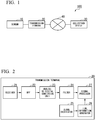
- FIG. 1 is a diagram showing a system configuration of a sensor system 100 according to a first embodiment.
- the sensor system 100 includes a sensor 10, a transmission terminal 20, and a collection device 30.
- the sensor 10 and the transmission terminal 20 are connected by a wire.
- the transmission terminal 20 and the collection device 30 are wirelessly connected via a network 40.
- the network 40 is, for example, a network of an industrial, scientific, and medical (ISM) band.
- the wireless connection between the transmission terminal 20 and the collection device 30 is not necessarily limited to a wireless LAN, and any communication scheme may be used as long as wireless communication is possible.
- the sensor system 100 may include a plurality of sensors 10 and a plurality of transmission terminals 20.
- the sensor 10 is a sensor configured to detect a physical quantity.
- the sensor 10 is, for example, an acoustic emission (AE) sensor, an acceleration sensor, a microphone, a temperature sensor, or the like.
- the sensor 10 may be another sensor as long as a physical quantity can be detected.
- the sensor 10 converts the detected physical quantity into an electrical signal.
- the sensor 10 transmits the electrical signal to the transmission terminal 20.
- the transmission terminal 20 transmits transmission data including time information to the collection device 30.
- the transmission terminal 20 detects an event on the basis of the electrical signal output from the sensor 10 and transmits transmission data including at least one or both of an occurrence time of the detected event (hereinafter referred to as "event detection time") and a transmission time to the collection device 30.
- the event is an event that has occurred outside or inside the device.
- an event will be described as an example of an event that has occurred outside the device (for example, an event based on a detection result of a sensor).
- the transmission time is a time at which the transmission terminal 20 has transmitted transmission data including information of an event detection time to the collection device 30.
- the collection device 30 collects the transmission data transmitted from the transmission terminal 20.
- the collection device 30 collects a plurality of transmission times and event detection times from one transmission terminal 20 for each sensor 10.
- the collection device 30 performs a process based on the collected transmission times, the collected event detection times, and reception times corresponding to the transmission times.
- the reception time corresponding to the transmission time is a time at which transmission data including information of the transmission time transmitted from the transmission terminal 20 has been received.
- FIG. 2 is a schematic block diagram showing a function of the transmission terminal 20 according to the first embodiment.
- the transmission terminal 20 includes a receiver 21, a BPF 22, an analog-to-digital conversion unit 23, a filter 24, a clock oscillator 25, a time information generator 26, and a signal processor 27.
- the receiver 21 receives an electrical signal transmitted from the sensor 10.
- the receiver 21 outputs the received electrical signal to the BPF 22.
- the BPF 22 removes noise from the electrical signal received by the receiver 21.
- the BPF 22 is a filter for removing noise.
- the BPF 22 outputs a noise-removed signal to the analog-to-digital conversion unit 23.
- the analog-to-digital conversion unit 23 converts an analog signal into a digital signal by quantizing the noise-removed signal output from the BPF 22.
- the analog-to-digital conversion unit 23 outputs the digital signal to the filter 24.
- the filter 24 removes noise from the digital signal output from the analog-to-digital conversion unit 23.
- the filter 24 is a filter for removing noise.
- the filter 24 outputs the noise-removed signal to the signal processor 27.
- the clock oscillator 25 generates a clock signal. Specifically, the clock oscillator 25 determines a time width of 1 sec in the transmission terminal 20.
- the clock oscillator 25 is configured using, for example, a voltage variable crystal oscillator such as a voltage controlled xtal oscillator (VCXO).
- VXO voltage controlled xtal oscillator
- the clock oscillator 25 outputs a clock signal to the time information generator 26.
- the time information generator 26 determines a time in the transmission terminal 20 in accordance with the clock signal output from the clock oscillator 25.
- the time information generator 26 is a counter having a register. That is, the time information generator 26 counts the number of edges of the clock signal and stores a cumulative count value from the power-on time of the transmission terminal 20 as time information in the register.
- the signal processor 27 determines an event detection time and a transmission time on the basis of a noise-removed digital signal output from the filter 24 and the time information generated by the time information generator 26.
- the event detection time may be, for example, the number of clocks, or may be hours:minutes:seconds.
- FIG. 3 is a schematic block diagram showing an internal configuration of the signal processor 27 according to the first embodiment.
- the signal processor 27 includes an event signal generator 271, an event time determiner 272, a communication time determiner 273, and a communicator 274.
- the event signal generator 271 generates a gate signal indicating whether or not a waveform of a noise-removed digital signal is being sustained.
- the event signal generator 271 is implemented by, for example, an envelope detector and a comparator.
- the envelope detector detects the envelope of the noise-removed digital signal.
- the envelope is extracted by, for example, squaring the noise-removed digital signal and performing a predetermined process (for example, a process using a low-pass filter or a Hilbert transform) on the squared output value.
- the comparator determines whether or not the envelope of the noise-removed digital signal is greater than or equal to a predetermined threshold value.
- the event signal generator 271 outputs a first gate signal indicating that the waveform of the noise-removed digital signal is being sustained to the event time determiner 272 when the envelope of the noise-removed digital signal is greater than or equal to a predetermined threshold value.
- a predetermined threshold value When the first gate signal has been output, this indicates that an event has occurred.
- the event signal generator 271 outputs a second gate signal indicating that the waveform of the noise-removed digital signal is not being sustained to the event time determiner 272.
- the second gate signal has been output, this indicates that the event has ended.
- ChangeFinder ChangeFinder, Akaike's Information Criterion (AIC), or the like may be used.
- the event time determiner 272 inputs either the first gate signal or the second gate signal output from the event signal generator 271 and the time information.
- the event time determiner 272 determines the event detection time on the basis of the input gate signal. Specifically, the event time determiner 272 determines a time when the envelope has been greater than or equal to a predetermined threshold value, i.e., a time when the first gate signal has been input as an event detection time.
- the communication time determiner 273 inputs time information.
- the communication time determiner 273 monitors the communicator 274 and determines a transmission time.
- the communication time determiner 273 may cause the communicator 274 to perform wireless communication at a time provided through a notification by determining the transmission time before wireless transmission and notifying the communicator 274 of the transmission time.
- the transmission time generally indicates a start time, but is not limited thereto as long as it is single.
- the communicator 274 may externally output a signal when transmission starts and the communication time determiner 273 may determine the transmission time according to the signal.
- the communication time determiner 273 may determine the transmission time during wireless transmission, may incorporate the transmission time in the transmission data transmitted by the communicator 274, and may cause the transmission time to be transmitted after the end of wireless transmission.
- the communicator 274 is a communication interface that performs communication with the collection device 30 via the network 40.
- the communicator 274 transmits either or both of the generated event detection time and transmission time to the collection device 30 at a predetermined timing through wireless communication.
- the predetermined timing may be, for example, a timing when the time determined by the communication time determiner 273 has been reached or may be a timing when a predetermined period of time has elapsed after transmission was performed once.
- a radio frequency band for use in communication of the communicator 274 is, for example, a band such as 2.4 GHz or 920 MHz.
- the communicator 274 may include a storage unit.
- the storage unit has, for example, a dual port RAM and stores an event detection time and a transmission time.
- the storage unit is not necessarily provided in the communicator 274 and may be provided within the transmission terminal 20.
- the communicator 274 can also perform transmission at an appropriate timing so that the event detection time and the transmission time are transmitted together or the event detection time and the transmission time are transmitted separately.
- the power of the transmission terminal 20 is supplied from an external power source, a primary battery, a secondary battery, a solar battery, an energy harvester, or the like.
- the transmission terminal 20 is implemented from an analog circuit and a digital circuit.
- the digital circuit is implemented by, for example, an FPGA or a microcomputer.
- the digital circuit may be implemented by a dedicated LSI.
- the transmission terminal 20 may be equipped with a non-volatile memory such as a flash memory or a removable memory.
- FIG. 4 is a schematic block diagram showing a function of the collection device 30 according to the first embodiment.
- the collection device 30 includes a central processing unit (CPU), a memory, an auxiliary storage device, and the like connected by a bus, and executes a collection program. By executing the collection program, the collection device 30 functions as a device including a clock oscillator 31, a time information generator 32, a communicator 33, a reception time determiner 34, and a time information processor 35. Also, all or some of functions of the collection device 30 may be implemented using hardware such as an application specific integrated circuit (ASIC), a programmable logic device (PLD), or a field programmable gate array (FPGA). Also, the collection program may be recorded on a computer-readable recording medium.
- ASIC application specific integrated circuit
- PLD programmable logic device
- FPGA field programmable gate array
- the collection program may be recorded on a computer-readable recording medium.
- the computer-readable recording medium is, for example, a flexible disk, a magneto-optical disk, a ROM, a portable medium such as a CD-ROM, or a storage device such as a hard disk built into the computer system.
- the collection program may be transmitted/received via a telecommunication circuit.
- the clock oscillator 31 generates a clock signal. Specifically, the clock oscillator 31 determines a time width of 1 sec in the collection device 30.
- the clock oscillator 31 is configured using, for example, a voltage variable crystal oscillator such as a VCXO.
- the clock oscillator 31 outputs a clock signal to the time information generator 32.
- the time information generator 32 determines a time in the collection device 30 according to the clock signal output from the clock oscillator 25.
- the time information generator 32 is a counter having a register. That is, the time information generator 32 counts the number of edges of the clock signal and stores a cumulative count value from the power-on time of the collection device 30 as time information in the register.
- the communicator 33 is a communication interface that performs communication with the transmission terminal 20 via the network 40.
- the communicator 33 receives information of the event detection time and the transmission time transmitted from the transmission terminal 20.
- the reception time determiner 34 determines a reception time on the basis of a received signal. Specifically, the reception time determiner 34 determines a time at which the signal transmitted from the transmission terminal 20 has been received by the communicator 33 as the reception time.
- the reception time generally indicates a reception start time, a time when a preamble has been discovered, or a synchronization word discovery time, but is not limited thereto.
- the time information processor 35 estimates an event detection time when an event occurs by statistically processing a plurality of transmission times and a plurality of reception times that have been received.
- the time information processor 35 includes a storage unit that stores information of the transmission time and event detection time received by the communicator 33 and the estimated event detection time.
- FIGS. 5 and 6 are explanatory diagrams showing time processing according to the first embodiment.
- the transmission terminal 20 acquires the event detection time by means of the event time determiner 272 and transmits information of the event detection time to the collection device 30 by means of the communicator 274. Specifically, when an event occurs, the transmission terminal 20 first determines a time T 0 when the event has occurred as the event detection time. Next, the transmission terminal 20 generates transmission data including the event detection time T 0 and a transmission time T 1 and transmits the generated transmission data to the collection device 30 at the time T 1 . The collection device 30 receives the transmission data transmitted from the transmission terminal 20. The collection device 30 determines a time T' 1 when the transmission data has been received as a reception time.
- the collection device 30 determines the reception time in the reception time determiner 34 every time transmission data including at least the transmission time is received from the transmission terminal 20. As shown in FIG. 5 , when an event occurs earlier than the transmission operation, transmission by the transmission terminal 20 is on standby and transmission is started at an available transmission timing.
- FIG. 6 shows a relationship between a transmission time of the transmission terminal 20 and a reception time of the collection device 30.
- the collection device 30 obtains a graph shown in FIG. 6 on the basis of reception time information and transmission time information transmitted from the transmission terminal 20.
- the collection device 30 can obtain a relationship related to times such as a transmission time T 1 and a reception time T' 1 and a transmission time T 2 and a reception time T' 2 .
- the collection device 30 statistically processes time stamps and counter values related to a plurality of pieces of transmission data, thereby acquiring a relationship between counter values and estimating an event detection time.
- the relationship between the counter values can be obtained by regression analysis and may be obtained in a scheme such as a least squares method or principal component analysis (PCA).
- PCA principal component analysis
- a parametric or non-parametric method may be used. Also, it is not necessary to wait for all events to occur. If two or more transmission times and two or more reception times can be obtained between one transmission terminal 20 and the collection device 30, the event detection time can be estimated.
- the collection device 30 may calculate a time difference (for example, a difference ⁇ T 32 between T 3 and T 2 ) obtained using a plurality of transmission times. In this case, the collection device 30 can convert the event detection time into necessary information without directly estimating the event detection time.
- a time difference for example, a difference ⁇ T 32 between T 3 and T 2
- FIG. 7 is a diagram showing a result of comparison between the conventional technology and the technology according to the present embodiment.
- the horizontal axis represents a time error
- the vertical axis represents a frequency distribution.
- a result of experimentally measuring the frequency distribution of the error of the event detection time estimated by the counter value of the collection device 30 when an event occurs simultaneously in a plurality of sensors 10 at fixed intervals and is received by the collection device 30 is shown.
- the result of ETA is shown. That is, the result of ETA is shown when no correction is applied.
- the error distribution extends to 2 ⁇ s or the like in addition to a large error of about 10 ⁇ s. This is considered to be caused by a clock error, a communication delay, a reception processing delay, and the like.
- the data is collected around an error of 0 ⁇ s.
- the circuit configuration can be simplified, the costs can be reduced, and the power consumption can be reduced. Also, even when the sensor 10 retransmits the detection result, the relationship is obtained according to the present process, so that the influence of the clock error is reduced.
- FIG. 8 is a diagram showing a specific example of the first transmission method performed by the transmission terminal 20 according to the first embodiment.
- the first transmission method is a method in which the transmission terminal 20 transmits an event detection time, a transmission time, and sensor data to the collection device 30 in a single transmission process at a timing when a random period of time has elapsed after the occurrence of the event. More specifically, the transmission terminal 20 determines the transmission time of the event detection time after the occurrence of the event and transmits transmission data including the event detection time, the sensor data, and the transmission time to the collection device 30 at the determined time. The collection device 30 generates a reception time when the transmission data transmitted from the transmission terminal 20 has been received.
- the first transmission method shown in FIG. 8 will be described as an example when the transmission terminal 20 determines an event detection time as a time T 1 and transmits information of the event detection time T 1 at the timing of a time T 2 .
- the transmission terminal 20 generates transmission data including the "event detection time T 1 ", a "transmission time T 2 ", and "sensor data” and transmits the generated transmission data to the collection device 30.
- the collection device 30 generates the reception time T' 1 when the transmission data transmitted from the transmission terminal 20 has been received.
- the transmission terminal 20 determines the event detection time after the occurrence of the event and transmits transmission data in which other necessary sensor data and the transmission time are combined to the collection device 30.
- a microprocessor cannot include its own exact transmission time in transmission data at the time of transmission or the like.
- FIG. 9 is a diagram showing a specific example of the second transmission method.
- the second transmission method is a method in which the transmission terminal 20 separately transmits an event detection time and a transmission time to the collection device 30 at a timing when a random period of time has elapsed after the occurrence of an event. More specifically, the transmission terminal 20 first transmits transmission data including an event detection time, sensor data, and a unique ID for identifying transmission data to the collection device 30 after the occurrence of the event. The collection device 30 generates a reception time when the transmission data transmitted from the transmission terminal 20 has been received. Next, the transmission terminal 20 determines a transmission time at the time of transmission of transmission data or after transmission thereof. Then, at the next transmission timing, the transmission terminal 20 transmits transmission data including the determined transmission time, a unique ID for identifying transmission data to be associated, and a unique ID for identifying transmission data to be currently transmitted to the collection device 30.
- the next transmission timing is a timing at which a predetermined period of time has elapsed from the transmission of transmission data including information of an event detection time.
- the next transmission timing may be after the transmission time is determined by the communication time determiner 273 and may be any timing if the next transmission timing is a random timing at which transmission is possible.
- the unique ID for identifying the transmission data to be associated is identification information for associating a reception time of the transmission data with a transmission time of the transmission data.
- the second transmission method shown in FIG. 9 will be described as an example when the transmission terminal 20 determines an event detection time as a time T 1 and transmits information of the event detection time T 1 at the timing of a time T 2 .
- the transmission terminal 20 generates transmission data including the "event detection time T 1 ", "sensor data”, and a "unique ID: A" for identifying the transmission data and transmits the generated transmission data to the collection device 30.
- the collection device 30 When the transmission data transmitted from the transmission terminal 20 has been received, the collection device 30 generates a "reception time T' 1 " that is a reception time of the transmission data including the unique ID: A.
- the transmission terminal 20 determines a transmission time at the time of transmission of transmission data or after transmission thereof.
- This transmission time is assumed to be T 2 .
- the transmission terminal 20 generates transmission data including a "transmission time T 2 " of the unique ID: A, the "unique ID: A” for identifying transmission data to be associated, and a “unique ID: B” for identifying transmission data to be currently transmitted and transmits the generated transmission data to the collection device 30.
- the collection device 30 can associate a transmission time "transmission time T 2 " of the transmission data including the "event detection time T 1 " with a previously received "reception time T' 1 " on the basis of the "unique ID: A” included in the received transmission data.
- the second transmission method is used when the transmission time of the information of the "event detection time” is not determined at the time of transmission.
- FIG. 10 is a diagram showing a specific example of a third transmission method.
- the third transmission method is a method in which the transmission terminal 20 transmits a transmission time of a previous event detection time, a current event detection time, and sensor data to the collection device 30 at a timing when a random period of time has elapsed after the occurrence of an event. More specifically, the transmission terminal 20 first transmits transmission data including the current event detection time, the sensor data, a unique ID for identifying transmission data, a transmission time of information of the previous event detection time, and a unique ID for identifying transmission data to be associated to the collection device 30 after the occurrence of the event.
- the collection device 30 generates a reception time when the transmission data transmitted from the transmission terminal 20 has been received.
- the transmission terminal 20 determines a transmission time at the time of transmission of transmission data or after transmission thereof. Then, after the next event occurs, the transmission terminal 20 transmits transmission data including a transmission time of a previous event detection time, sensor data, a current event detection time, a unique ID for identifying transmission data to be currently transmitted, and a unique ID for identifying transmission data to be associated to the collection device 30.
- the third transmission method shown in FIG. 10 will be described as an example when the transmission terminal 20 determines an event detection time as a time T 1 and transmits information of the event detection time T 1 at a timing of a time T 2 .
- the transmission terminal 20 generates transmission data including the "event detection time T 1 ", "sensor data”, a “transmission time T 0 " of the transmission data with the unique ID of "A”, a "unique ID: A” for identifying transmission data to be associated, and a "unique ID: B" for identifying transmission data and transmits the generated transmission data to the collection device 30.
- the collection device 30 When the transmission data including "unique ID: B" transmitted from the transmission terminal 20 has been received, the collection device 30 generates a "reception time T' 1 " of the unique ID: B. Next, the transmission terminal 20 determines a transmission time at the time of transmission of transmission data or after transmission thereof. This transmission time is assumed to be T 2 . Then, after the next event occurs, the transmission terminal 20 generates transmission data including a "transmission time T 3 " of an event detection time, sensor data, a "transmission time T 2 " of transmission data with a unique ID of "B", a "unique ID: B” for identifying transmission data to be associated, and a "unique ID: C” for identifying transmission data to be currently transmitted and transmits the generated transmission data to the collection device 30.
- the collection device 30 can associate the "transmission time T 2 " which is the transmission time of transmission data including an "event detection time T 1 " with a "reception time T' 1 " that has been transmitted at the "transmission time T 2 " and received on the basis of the "unique ID: B" included in the received transmission data.
- the third transmission method is used when the transmission time of the information of the "event detection time” is not determined at the time of transmission, as in the second transmission method.
- the third transmission method is different from the second transmission method in that the information of a transmission time associated with the information of an event detection time that has already been transmitted is included in transmission data of a subsequent event.
- the associated event detection time and transmission time are not included in the same packet.
- a transmission processing error, packet loss, and order are assumed to be changed according to transmission. Therefore, in the second transmission method and the third transmission method described above, it is possible to easily perform the association by adding a unique ID, a counter value of the number of transmissions, and the like in order to associate the transmission packet with the transmission time. Accordingly, even when the transmission order of the packet corresponding to the event is changed, the association is possible.
- the unique ID is not essential when the correspondence can be understood without the unique ID.
- FIG. 11 is a diagram showing a specific example of a fourth transmission method.
- the fourth transmission method is a method in which the transmission terminal 20 transmits a transmission time to the collection device 30 by causing a dummy event to occur before and after the occurrence of an event.
- the dummy event is an event whose occurrence has not been detected by the event signal generator 271 and which has not actually occurred. That is, the dummy event is a virtual event. More specifically, the transmission terminal 20 first transmits transmission data including an event detection time, a transmission time, and sensor data to the collection device 30 before and after the occurrence of the event. Next, the transmission terminal 20 transmits transmission data including the transmission time to the collection device 30 after the occurrence of the dummy event.
- the communication time determiner 273 may cause the dummy event to occur, the communicator 274 may cause the dummy event to occur, or the transmission terminal 20 may cause the dummy event to occur by newly providing a dummy event generator.
- the fourth transmission method shown in FIG. 11 will be described as an example when the transmission terminal 20 determines an event detection time as a time T 1 and transmits information of the event detection time T 1 at a timing of a time T 2 .
- the transmission terminal 20 generates transmission data including an "event detection time T 1 ", a "transmission time T 2 ", and "sensor data” and transmits the generated transmission data to the collection device 30.
- the collection device 30 generates a "reception time T' 1 ".
- the transmission terminal 20 causes a dummy event to occur, generates transmission data including a transmission time "transmission time T 4 " at the next transmission timing, and transmits the generated transmission data to the collection device 30.
- the fourth transmission method is used when an event occurs only once within a certain period.
- the transmission terminal 20 transmits the event detection time, the transmission time, and the sensor data to the collection device 30 in a single transmission process as in the first transmission method in the fourth transmission method shown in FIG. 11 is shown, the event detection time and the transmission time may be transmitted at different timings.
- transmission data is transmitted after the occurrence of an event as shown in FIG. 11 and the transmission terminal 20 generates a dummy event, transmits transmission data, and increases the transmission time and the reception time to enhance an estimation system. It is only necessary to include at least the transmission time in the transmission data transmitted by the transmission terminal 20 in the dummy event.
- the transmission terminal 20 may use a combination of the first to fourth transmission methods shown in FIGS. 8 to 11 .
- the transmission terminal 20 may perform transmission in the first transmission method at the time of first transmission and perform transmission in the second transmission method at the time of second transmission.
- FIG. 12 is a sequence diagram showing a flow of a process performed by the sensor system 100 according to the first embodiment. An example in which the transmission terminal 20 transmits transmission data in the first transmission method will be described with reference to FIG. 12 .
- the sensor 10 detects a physical quantity (step S101).
- the sensor 10 converts the detected physical quantity into an electrical signal.
- the sensor 10 transmits the electrical signal indicating a detection result to the transmission terminal 20 (step S102).
- the receiver 21 of the transmission terminal 20 receives the electrical signal transmitted from the sensor 10.
- the transmission terminal 20 performs preprocessing on the received electrical signal (step S103).
- the event signal generator 271 detects the occurrence of an event on the basis of a preprocessed signal (step S104).
- the event signal generator 271 outputs a first gate signal to the event time determiner 272.
- the event time determiner 272 determines a time when the first gate signal has been input as an event detection time (step S105).
- the event time determiner 272 outputs information of the determined event detection time to the communicator 274.
- the event time determiner 272 also outputs the sensor data obtained from the sensor 10 to the communicator 274.
- the communication time determiner 273 inputs the time information generated by the time information generator 26.
- the communication time determiner 273 determines the transmission time on the basis of the input time information (step S106).
- the communication time determiner 273 outputs information of the determined transmission time to the communicator 274.
- the communicator 274 generates transmission data including an event detection time and sensor data output from the event time determiner 272 and the transmission time output from the communication time determiner 273.
- the communicator 274 transmits the generated transmission data to the collection device 30 (step S107).
- the communicator 33 of the collection device 30 receives the transmission data transmitted from the transmission terminal 20.
- the communicator 33 outputs the received transmission data to the reception time determiner 34 and the time information processor 35.
- the reception time determiner 34 determines the reception time on the basis of the time information generated by the time information generator 32 and the transmission data output from the communicator 33 (step S108).
- the reception time determiner 34 determines a time indicated by the time information of a point in time at which the transmission data has been obtained as a reception time.
- the reception time determiner 34 outputs information of the determined reception time to the time information processor 35.
- the time information processor 35 saves the transmission data output from the communicator 33 and the information of the reception time output from the reception time determiner 34 in association in the storage unit.
- the sensor 10 detects a physical quantity (step S109).
- the sensor 10 converts the detected physical quantity into an electrical signal.
- the sensor 10 transmits an electrical signal indicating a detection result to the transmission terminal 20 (step S110).
- the receiver 21 of the transmission terminal 20 receives the electrical signal transmitted from the sensor 10.
- the transmission terminal 20 performs preprocessing on the received electrical signal (step S111).
- the event signal generator 271 detects the occurrence of an event on the basis of the preprocessed signal (step S112).
- the event signal generator 271 outputs a first gate signal to the event time determiner 272.
- the event time determiner 272 determines a time when the first gate signal has been input as an event detection time (step S113).
- the communication time determiner 273 inputs the time information generated by the time information generator 26.
- the communication time determiner 273 determines a transmission time on the basis of the input time information (step S114).
- the communication time determiner 273 outputs information of the determined transmission time to the communicator 274.
- the communicator 274 generates transmission data including an event detection time and sensor data output from the event time determiner 272 and the transmission time output from the communication time determiner 273.
- the communicator 274 transmits the generated transmission data to the collection device 30 (step S115).
- the communicator 33 of the collection device 30 receives the transmission data transmitted from the transmission terminal 20.
- the communicator 33 outputs the received transmission data to the reception time determiner 34 and the time information processor 35.
- the reception time determiner 34 determines a reception time on the basis of the time information generated by the time information generator 32 and the transmission data output from the communicator 33 (step S116).
- the reception time determiner 34 outputs information of the determined reception time to the time information processor 35.
- the time information processor 35 saves the transmission data output from the communicator 33 and the information of the reception time output from the reception time determiner 34 in association in the storage unit.
- the time information processor 35 obtains a relationship between the transmission time and the reception time on the basis of information of a plurality of transmission times and information of a plurality of reception times saved in the storage unit (step S117).
- the time information processor 35 obtains the graph shown in FIG. 6 using the information of the plurality of transmission times and the information of the plurality of reception times. Subsequently, the time information processor 35 estimates the event detection time in the collection device 30 using the relationship between the transmission time and the reception time obtained from the obtained graph and the event detection time (step S118).
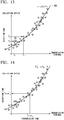
- FIGS. 13 to 15 are explanatory diagrams showing a specific process of the time information processor 35 according to the first embodiment. Also, in FIGS. 13 to 15 , a propagation period of time between the transmission terminal 20 and the collection device 30 is assumed to be known or negligibly small.
- the graph shown in FIG. 13 is assumed to be obtained on the basis of a transmission time of the transmission terminal 20 and a reception time of the collection device 30 obtained when time processing as shown in FIG. 5 has been performed.
- y represents a reception time (T')
- f(x) represents a model function
- x represents a transmission time (T)
- ⁇ represents an error.
- a line 80 is a line representing the relationship between the transmission time of the transmission terminal 20 and the reception time of the collection device 30. This line 80 can be obtained by the regression analysis as described above.
- a position of the point 81 obtained by a corresponding relationship between the transmission time and the reception time is slightly deviated from the line 80. This deviation is an error.
- a unique clock is embedded in each of the transmission terminal 20 and the collection device 30.
- the time of the clock is deviated if power-on timings are different and the time of the clock is deviated if the speeds of clocks are not exactly identical.
- the accuracy of the transmission time and the accuracy of the reception time also have an influence, there are not a few errors as shown in FIG. 13 .
- the error is T i ⁇ ⁇ f T i .
- i is an integer of 1 or more.
- the time information processor 35 estimates the event detection time by finding f for minimizing J in the following Eq. (1).
- a plurality of transmission times and a plurality of reception times are input and a relationship between the transmission time and the reception time is obtained.
- the transmission time is based on the time in the transmission terminal 20.
- the reception time is based on the time in the collection device 30. Therefore, the collection device 30 can acquire information for estimating (correcting) the event detection time by obtaining the relationship between the transmission time and the reception time.
- the collection device 30 estimates an event detection time using the acquired information. Thereby, errors related to a clock or errors due to priority processing in a microprocessor are averaged as compared with the case in which only the reception time stamp (reception time) is used or the estimation method such as ETA is used. Thus, the error in the event detection time can be reduced. As a result, the synchronization accuracy can be improved.
- the event signal generator 271 may be configured to detect an event on the basis of information inside the transmission terminal 20.
- the information inside the transmission terminal 20 includes time information, errors, and the like.
- the transmission terminal 20 may not include the sensor 10.
- the transmission terminal 20 may be configured to include a clock oscillator 25, a time information generator 26, and a signal processor 27.
- the collection device 30 may be implemented in another device (for example, a server located in a network higher than the collection device 30).
- the time information processor 35 provided in the collection device 30 may be mounted on another device.
- the collection device 30 determines data collection and reception times.
- the time information processor 35 estimates the event detection time.
- the collection device 30 is an aspect of the time information processing device.
- the collection device 30 may be configured to calculate a time difference between transmission times and a time difference between reception times corresponding to the transmission times and obtain a graph showing a relationship between the calculated time difference between the transmission times and the calculated time difference between the reception times corresponding to the transmission times.
- the time difference between the transmission times is, for example, a time difference between transmission times that are adjacent to each other in a plurality of transmission times.
- a time difference between T1 and T2 is time differences between transmission times adjacent to each other.
- FIG. 16 is a diagram showing a system configuration of a sensor system 100a according to the second embodiment.
- the sensor system 100a includes a plurality of sensors 10-1 to 10-n (n is an integer of 3 or more), a plurality of transmission terminals 20a-1 to 20a-n, a plurality of collection devices 30a-1 to 30a-n, and a server device 50.
- the sensor 10-1 and the transmission terminal 20a-1, the sensor 10-2 and the transmission terminal 20a-2, and the sensor 10-n and the transmission terminal 20a-n are connected by wire.
- Each of the plurality of transmission terminals 20a-1 to 20a-n and the collection device 30a are wirelessly connected via the network 40.
- the collection device 30a and the server device 50 are connected with priority or wirelessly via the network 60.
- the network 60 may be a LAN or the Internet.
- the sensors 10-1 to 10-n will be described as sensors 10 when they are not distinguished.
- the transmission terminals 20a-1 to 20a-n will be described as transmission terminals 20a when they are not distinguished.
- the collection devices 30a-1 to 30a-n will be described as collection devices 30a when they are not distinguished.
- a case in which one sensor 10 is connected to one transmission terminal 20a is shown in FIG. 16 , a plurality of sensors 10 may be connected to one transmission terminal 20a.
- the functional units in the device are described separately, the functional units are distinguished by adding branch numbers thereto. For example, when functional units included in the transmission terminal 20a-1 are described, a branch number of -1 is attached to distinguish the functional units from those of other devices.
- the sensor 10 is installed in a structure.
- the sensor 10 is installed on a concrete floor slab of a bridge.
- the sensor 10 has a piezoelectric element and detects elastic waves generated from the inside of the structure.
- the sensor 10 is installed at a position where elastic waves can be detected.
- the sensor 10 is installed on any one of a front surface, a side surface, and a bottom surface of a structure.
- the sensor 10 converts the detected elastic waves into an electric signal that is a voltage signal.
- the sensor 10 outputs the electrical signal to the transmission terminal 20a.
- the sensor 10 will be described as an example of an AE sensor or an acceleration sensor.
- the structure need not be limited to a bridge.
- the structure may be any structure as long as elastic waves are generated due to the occurrence or progress of a crack or an external impact (for example, rain, artificial rain, or the like).
- the structure may be a rock.
- Bridges are not limited to structures laid on rivers, valleys, or the like, and also include various structures (for example, highway viaducts) provided above the ground and the like.
- the transmission terminal 20a according to the second embodiment is similar to that according to the first embodiment except for the signal processor. Thus, only the signal processor 27a will be described.
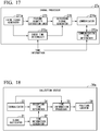
- FIG. 17 is a schematic block diagram showing an internal configuration of the signal processor 27a according to the second embodiment.
- the signal processor 27a includes an event signal generator 271a, an event time determiner 272a, a communication time determiner 273a, a communicator 274a, a feature quantity extraction unit 275, and a detection signal generator 276.
- the event signal generator 271a performs a process similar to that of the event signal generator 271.
- the event signal generator 271a outputs a first gate signal or a second gate signal to the event time determiner 272a and the feature quantity extraction unit 275.
- the event time determiner 272a performs a process similar to that of the event time determiner 272.
- the event time determiner 272a outputs information of an event detection time to the detection signal generator 276 so that a determined event detection time is associated with a feature quantity.
- the communication time determiner 273a performs a process similar to that of the communication time determiner 273.
- the communicator 274a is a communication interface that performs communication with the collection device 30a via the network 40.
- the communicator 274a inputs detection information output from the detection signal generator 276 and a transmission time output from the communication time determiner 273a.
- the communicator 274a may have a storage unit.
- the storage unit has, for example, a dual port RAM, and stores the detection information and the transmission time.
- the storage unit is not necessarily provided in the communicator 274a and may be provided in the transmission terminal 20a.
- the communicator 274a transmits the detection information and the transmission time to the collection device 30a at a predetermined timing according to wireless communication.
- a radio frequency band for use in communication of the communicator 274a is, for example, a band such as 2.4 GHz or 920 MHz.
- the communicator 274a can also transmit the detection information and the transmission time together or transmit the detection information and the transmission time separately at an appropriate timing.
- the feature quantity extraction unit 275 extracts a feature quantity when the signal waveform continues on the basis of the gate signal output from the event signal generator 271a.
- the feature quantity is information indicating a feature of the signal.
- the feature quantity includes an amplitude [mV] of the waveform of the signal, a rising time [ ⁇ sec] of the gate signal, the duration [ ⁇ sec] of the gate signal, a zero cross count number [times] of the duration waveform, signal energy [arb.], a frequency [Hz], and the like.
- the feature quantity extraction unit 275 inputs the feature quantity to the detection signal generator 276.
- the detection signal generator 276 receives the feature quantity from the feature quantity extraction unit 275 and receives the event detection time from the event time determiner 272a.
- the detection signal generator 276 generates detection information in which the feature quantity is associated with the event detection time, and outputs the generated detection information to the communicator 274a. Also, the detection signal generator 276 also outputs sensor data to the communicator 274a when the sensor data has been obtained from the event time determiner 272a.
- the power of the transmission terminal 20a is supplied from an external power source, a primary battery, a secondary battery, a solar battery, an energy harvester, or the like.
- the transmission terminal 20a is implemented from an analog circuit and a digital circuit.
- the digital circuit is implemented by, for example, an FPGA or a microcomputer.
- the digital circuit may be implemented by a dedicated LSI.
- the transmission terminal 20a may be equipped with a non-volatile memory such as a flash memory or a removable memory.
- FIG. 18 is a schematic block diagram showing a function of the collection device 30a according to the second embodiment.
- the collection device 30a includes a CPU, a memory, an auxiliary storage device, and the like connected by a bus and executes a collection program. By executing the collection program, the collection device 30a functions as a device including a clock oscillator 31, a time information generator 32, a communicator 33, a reception time determiner 34, a time information processor 35, and a position locator 36. Also, all or some of the functions of the collection device 30a may be implemented using hardware such as an ASIC, a PLD, or an FPGA. Also, the collection program may be recorded on a computer-readable recording medium.
- the computer-readable recording medium is, for example, a flexible disk, a magneto-optical disk, a ROM, a portable medium such as a CD-ROM, or a storage device such as a hard disk built into a computer system.
- the collection program may be transmitted and received via a telecommunication circuit.
- a configuration of the collection device 30a is different from the configuration of the collection device 30 in that the position locator 36 is newly provided.
- the collection device 30a is similar to the collection device 30 in terms of other configurations. Thus, the description of the whole of the collection device 30a will be omitted and the position locator 36 will be described.
- the position locator 36 inputs a result of estimating an event detection time and detection information output from the time information processor 35.
- the position locator 36 locates a position of an elastic wave generation source on the basis of the result of estimating the event detection time and the detection information that have been input.
- FIG. 19 is a sequence diagram showing a flow of a process performed by the sensor system 100 according to the second embodiment.
- a case in which there are three sensors 10 (sensors 10-1 to 10-3), three transmission terminals 20a (transmission terminals 20a-1 to 20-3), and one collection device 30a will be described as an example with reference to FIG. 19 .
- the sensor 10-1 is connected to the transmission terminal 20a-1
- the sensor 10-2 is connected to the transmission terminal 20a-2
- the sensor 10-3 is connected to the transmission terminal 20a-3.
- the sensors 10-1 to 10-3 perform similar processes except that connection destinations are different, only the sensors 10-1 and 10-3 will be described with reference to FIG. 19 .
- the transmission terminals 20a-1 to 20-3 perform similar processes except that connection destinations are different, only the transmission terminals 20a-1 and 20a-3 will be described with reference to FIG. 19 .
- the sensor 10-1 detects a physical quantity (step S201).
- the sensor 10-1 converts the detected physical quantity into an electrical signal.
- the sensor 10-1 transmits an electrical signal indicating the detection result to the transmission terminal 20a-1 (step S202).
- the sensor 10-3 detects a physical quantity (step S203).
- the sensor 10-3 converts the detected physical quantity into an electrical signal.
- the sensor 10-3 transmits an electrical signal indicating the detection result to the transmission terminal 20a-3 (step S204).
- the receiver 21-1 receives the electrical signal transmitted from the sensor 10-1.
- the transmission terminal 20a-1 performs preprocessing on the received electrical signal (step S205).
- the event signal generator 271a-1 detects the occurrence of an event on the basis of a preprocessed signal (step S206).
- the event signal generator 271a-1 outputs a first gate signal to the event time determiner 272a-1 and the feature quantity extraction unit 275-1.
- the feature quantity extraction unit 275-1 extracts a feature quantity from the preprocessed signal when the first gate signal output from the event signal generator 271a-1 has been input (step S207).
- the feature quantity extraction unit 275-1 outputs the extracted feature quantity to the detection signal generator 276-1.
- the event time determiner 272a-1 determines a time at which the first gate signal has been input as the event detection time (step S208).
- the event time determiner 272a-1 outputs information of the determined event detection time to the detection signal generator 276-1.
- the event time determiner 272a-1 also outputs sensor data obtained from the sensor 10-1 to the detection signal generator 276-1.
- the detection signal generator 276-1 inputs the feature quantity output from the feature quantity extraction unit 275-1 and the event detection time and the sensor data output from the event time determiner 272a-1.
- the detection signal generator 276-1 generates detection information in which the feature quantity, the event detection time, and the sensor data are associated and outputs the generated detection information to the communicator 274a-1.
- the communication time determiner 273a-1 inputs time information generated by the time information generator 26-1.
- the communication time determiner 273a-1 determines the transmission time on the basis of the input time information (step S209).
- the communication time determiner 273a-1 outputs information of the determined transmission time to the communicator 274a-1.
- the communicator 274a-1 generates transmission data including detection information output from the detection signal generator 276-1 and the transmission time output from the communication time determiner 273a-1.
- the communicator 274a-1 transmits the generated transmission data to the collection device 30a (step S210).
- the communicator 33 of the collection device 30a receives the transmission data transmitted from the transmission terminal 20a-1.
- the communicator 33 outputs the received transmission data to the reception time determiner 34 and the time information processor 35.
- the reception time determiner 34 determines a reception time on the basis of the time information generated by the time information generator 32 and the transmission data output from the communicator 33 (step S211). Specifically, the reception time determiner 34 determines a time indicated by time information of a point in time at which the transmission data has been obtained as the reception time.
- the reception time determiner 34 outputs information of the determined reception time to the time information processor 35.
- the time information processor 35 saves the transmission data output from the communicator 33 and the information of the reception time output from the reception time determiner 34 in association in the storage unit for each sensor 10.
- the receiver 21-3 receives an electrical signal transmitted from the sensor 10-3.
- the transmission terminal 20a-3 performs preprocessing on the received electrical signal (step S212).
- the event signal generator 271a-3 detects the occurrence of an event on the basis of a preprocessed signal (step S213).
- the event signal generator 271a-3 outputs a first gate signal to the event time determiner 272a-3 and the feature quantity extraction unit 275-3.
- the feature quantity extraction unit 275-3 extracts a feature quantity from the preprocessed signal when the first gate signal output from the event signal generator 271a-3 has been input (step S214).
- the feature quantity extraction unit 275-3 outputs the extracted feature quantity to the detection signal generator 276-3.
- the event time determiner 272a-3 determines a time at which the first gate signal has been input as the event detection time (step S215).
- the event time determiner 272a-3 outputs information of the determined event detection time to the detection signal generator 276-3.
- the event time determiner 272a-3 outputs sensor data obtained from the sensor 10-3 to the detection signal generator 276-3.
- the detection signal generator 276-3 inputs a feature quantity output from the feature quantity extraction unit 275-3 and the event detection time and sensor data output from the event time determiner 272a-3.
- the detection signal generator 276-3 generates detection information in which the feature quantity, the event detection time, and the sensor data are associated and outputs the generated detection information to the communicator 274a-3.
- the communication time determiner 273a-3 inputs the time information generated by the time information generator 26-3.
- the communication time determiner 273a-3 determines a transmission time on the basis of the input time information (step S216).
- the communication time determiner 273a-3 outputs information of the determined transmission time to the communicator 274a-3.
- the communicator 274a-3 generates transmission data including detection information output from the detection signal generator 276-3 and the transmission time output from the communication time determiner 273a-3.
- the communicator 274a-3 transmits the generated transmission data to the collection device 30a (step S217).
- the communicator 33 of the collection device 30a receives the transmission data transmitted from the transmission terminal 20a-3.
- the communicator 33 outputs the received transmission data to the reception time determiner 34 and the time information processor 35.
- the reception time determiner 34 determines a reception time on the basis of the time information generated by the time information generator 32 and the transmission data output from the communicator 33 (step S218). Specifically, the reception time determiner 34 determines a time indicated by the time information of a point in time at which the transmission data has been obtained as the reception time.
- the reception time determiner 34 outputs information of the determined reception time to the time information processor 35.
- the time information processor 35 saves the transmission data output from the communicator 33 and the reception time information output from the reception time determiner 34 in association in the storage unit for each sensor 10.
- steps S201 to S218 is iteratively executed.
- the collection device 30a executes the processing of step S219.
- the collection device 30a executes the processing of step S219.
- the time information processor 35 obtains the relationship between the transmission time and the reception time for each sensor 10 on the basis of the information of the plurality of transmission times and the information of the plurality of reception times saved in the storage unit (step S219). Specifically, the time information processor 35 obtains the graph shown in FIG. 6 using the information of the plurality of transmission times and the information of the plurality of reception times. Subsequently, the time information processor 35 estimates the event detection time for each sensor 10 from the relationship between the transmission time and the reception time obtained from the obtained graph (step S220). The time information processor 35 outputs the event detection time and detection information to the position locator 36.
- the position locator 36 locates a position of an elastic wave generation source on the basis of the event detection time and the detection information (step S221). Specifically, the position locator 36 first calculates a similarity of feature quantity information included in the detection information and divides a plurality of pieces of detection information into groups on the basis of whether or not the similarity of the feature quantity information is greater than or equal to a predetermined threshold value. Then, the position locator 36 recognizes the detection information included in the same group as detection information of the same generation source.
- the similarity is determined by a distance between feature quantity information and feature quantity information. That is, the similarity increases as a distance between different pieces of feature quantity information decreases.
- the position locator 36 calculates a distance between pieces of feature quantity information according to a predetermined distance function.
- the distance function is a function for calculating, for example, a standard Euclidean distance, a Minkowski distance, a Mahalanobis distance, or the like.
- the Mahalanobis distance can be calculated in consideration of a correlation between pieces of feature quantity information and the group classification accuracy can be improved.
- the position locator 36 calculates time difference information of the reception times of elastic waves between the plurality of sensors 10 by comparing estimated event detection times associated with feature quantity information (feature quantity information of detection information included in the same group) whose similarity is greater than or equal to a predetermined threshold value.
- the position locator 36 identifies position information of the elastic wave generation source on the basis of the position information, the time difference information, and the propagation speed of elastic waves between the sensors 10.
- the sensor system 100a can detect a difference between occurrence times of a plurality of events and can wirelessly locate a vibration generation source and a lightning generation position by a low-cost terminal.
- event detection times between the plurality of sensors 10 are substantially the same time.
- a wireless collision can be prevented by waiting for a fixed random time after event detection.
- FIG. 20 is an explanatory diagram showing an example of the position identification method according to the second embodiment (a one-dimensional case).
- a case in which a structure crack occurs between the sensors 10-1 and 10-2 and each of the sensors 10-1 and 10-2 detects elastic waves due to the crack will be described with reference to FIG. 20 .
- a distance between the sensor 10-1 and the sensor 10-2 is assumed to be 1.
- a distance from an intermediate point between the sensor 10-1 and the sensor 10-2 to the crack is represented by ⁇ x.
- ⁇ t can be represented by the following Eq. (3).
- the position locator 36 can calculate a distance ⁇ x from an intermediate point between the sensor 10-1 and the sensor 10-2 to the crack on the basis of Eq. (3) by calculating a time difference information ⁇ t. That is, the position locator 36 can identify the position information of the crack (the elastic wave generation source) from the time difference information ⁇ t.
- FIG. 21 is an explanatory diagram showing an example of the position identification method according to the second embodiment (the two-dimensional case).
- An example in which a crack is generated in the structure and elastic waves due to the crack reach each of the sensors 10-1 to 10-4 at the propagation velocity v [m/s] is shown in FIG. 21 .
- the time at which the elastic waves reach each of the sensors 10-1 to 10-4 differs according to each of the sensors 10-1 to 10-4.
- the position locator 36 can identify an intersection of the circumferences ARC_1 to ARC 4 as position information of the elastic wave generation source.
- the position of the elastic wave generation source can be identified using (number of dimensions + 1) sensors 10. Therefore, in the three-dimensional case, it is possible to identify the position of the elastic wave generation source using the four sensors 10. Also, as the number of sensors 10 increases, the identification accuracy of the position information can increase.
- an event detection time for each sensor 10 is estimated on the basis of information obtained from each sensor 10. Specifically, the collection device 30a estimates the event detection time according to correction that reduces the time error. Accordingly, because the collection device 30a locates a position of the event generation source on the basis of a corrected event detection time, the collection device 30a can locate the position with high accuracy.
- the collection device 30a may be installed in the server device 50.
- the time information processor 35 and the position locator 36 provided in the collection device 30a may be installed in the server device 50.
- the collection device 30a performs the data collection and the reception time determination and the server device 50 performs the event detection time estimation and the position location.
- the position locator 36 included in the collection device 30a may be installed in the server device 50.
- the collection device 30a performs the data collection, the reception time determination, and the event detection time estimation and the server device 50 performs the position location.
- the server device 50 includes at least the time information processor 35
- the server device 50 includes an acquisition unit that acquires all time information of an event detection time, a transmission time, and a reception time.
- the time information processor 35 performs a process on the basis of a plurality of transmission times and a plurality of reception times that have been acquired. A specific process is as described above.
- one of the collection device 30a and the server device 50 performs at least one of an event detection time estimation process and a position location process.
- the collection device 30a and the server device 50 are forms of a time information processing device.
- the collection device 30a may be configured to calculate a time difference between transmission times and a time difference between reception times corresponding to the transmission times for each transmission terminal 20a and obtain a graph indicating a relationship between the calculated time difference between the transmission times and the calculated time difference between the reception times corresponding to the transmission times for each transmission terminal 20a.
- the position locator 36 of the collection device 30a locates the position of the event generation source using time difference information obtained for each transmission terminal 20a, position information of each transmission terminal 20a, and the propagation speed of elastic waves.
- the event signal generator detects the occurrence of an event on the basis of the physical quantity detected by the sensor.
- the event time determiner determines an event detection time.
- the communication time determiner determines a transmission time at the time of transmission to the time information processing device.
- the communicator transmits time information of the transmission time and time information of the event detection time to the time information processing device.
- a reception time determiner determines a reception time of time information transmitted from the transmission terminal.
Landscapes
- Engineering & Computer Science (AREA)
- Health & Medical Sciences (AREA)
- Computer Networks & Wireless Communication (AREA)
- Signal Processing (AREA)
- General Health & Medical Sciences (AREA)
- Medical Informatics (AREA)
- Biomedical Technology (AREA)
- Public Health (AREA)
- Life Sciences & Earth Sciences (AREA)
- Computing Systems (AREA)
- General Business, Economics & Management (AREA)
- Business, Economics & Management (AREA)
- Epidemiology (AREA)
- Primary Health Care (AREA)
- Heart & Thoracic Surgery (AREA)
- Biophysics (AREA)
- Pathology (AREA)
- Physics & Mathematics (AREA)
- Molecular Biology (AREA)
- Surgery (AREA)
- Animal Behavior & Ethology (AREA)
- Veterinary Medicine (AREA)
- Arrangements For Transmission Of Measured Signals (AREA)
- Synchronisation In Digital Transmission Systems (AREA)
- Electric Clocks (AREA)
Abstract
Description
- Examples of the present invention relate to a sensor system, a transmission terminal, a time information processing device, and a synchronization method.
- In recent years, various types of sensing data have been able to be collected due to power saving and price reduction of sensors and the development of networks. Thus, there is an active movement for utilizing sensing data. A method of utilizing sensing data is structural health monitoring. The structural health monitoring is technology for sensing physical quantities such as displacement, vibration, and pressure by means of sensors installed on structures such as bridges, and diagnosing damage and deterioration states of structures using various signal processing techniques. In such a monitoring system, not only single sensor information but also mutual information between a plurality of sensors is important and accurate time acquisition is required. Because the same clock can be used when a single terminal device and a sensor are connected using wires, little time error in the sensor information occurs. On the other hand, in the case of a system including a plurality of terminal devices using a wireless network, time synchronization is necessary because there are a plurality of clocks. As an example of such time synchronization, a method using a flooding time synchronization protocol (FTSP) in which a sensor and a server communicate with each other and a method using elapsed time on arrival (ETA) are known.
- In the above-described method, two-way communication is necessary and the correction of a time on the sensor side is necessary, such that the reception power and the amount of processing of the sensor increase. In FTSP, in order to deliver the time of the server to the sensor side, it is necessary to perform reception periodically for accurate synchronization. In ETA, because the sensor only needs to transmit a difference between a sensing time and a transmission time to the server, this problem caused in FTSP can be solved.
- However, when instability of a clock for generating a time, a transmission delay due to carrier sense or the like, and retransmission due to a packet error occur and a central processing unit (CPU) or the like is interrupted by another process, a process changes. Thus, synchronization accuracy may be reduced.
-
-
FIG. 1 is a diagram showing a system configuration of a sensor system according to a first embodiment. -
FIG. 2 is a schematic block diagram showing a function of a transmission terminal according to the first embodiment. -
FIG. 3 is a schematic block diagram showing an internal configuration of a signal processing unit according to the first embodiment. -
FIG. 4 is a schematic block diagram showing a function of a collection device according to the first embodiment. -
FIG. 5 is an explanatory diagram showing time processing according to the first embodiment. -
FIG. 6 is an explanatory diagram showing time processing according to the first embodiment. -
FIG. 7 is a diagram showing a result of comparison between conventional technology and technology according to the present embodiment. -
FIG. 8 is a diagram showing a specific example of a first transmission method performed by a transmission terminal according to the first embodiment. -
FIG. 9 is a diagram showing a specific example of a second transmission method performed by the transmission terminal according to the first embodiment. -
FIG. 10 is a diagram showing a specific example of a third transmission method performed by the transmission terminal according to the first embodiment. -
FIG. 11 is a diagram showing a specific example of a fourth transmission method performed by the transmission terminal according to the first embodiment. -
FIG. 12 is a sequence diagram showing a flow of a process performed by the sensor system according to the first embodiment. -
FIG. 13 is an explanatory diagram showing a specific process of the time information processing unit according to the first embodiment. -
FIG. 14 is an explanatory diagram showing a specific process of the time information processing unit according to the first embodiment. -
FIG. 15 is an explanatory diagram showing a specific process of the time information processing unit according to the first embodiment. -
FIG. 16 is a diagram showing a system configuration of a sensor system according to a second embodiment. -
FIG. 17 is a schematic block diagram showing an internal configuration of a signal processing unit according to the second embodiment. -
FIG. 18 is a schematic block diagram showing a function of a collection device according to the second embodiment. -
FIG. 19 is a sequence diagram showing a flow of a process performed by the sensor system according to the second embodiment. -
FIG. 20 is an explanatory diagram showing an example of a position identification method according to the second embodiment (a one-dimensional case). -
FIG. 21 is an explanatory diagram showing an example of a position identification method according to the second embodiment (a two-dimensional case). - The present invention provides a problem to be solved by the present invention is to provide a sensor system, a transmission terminal, a time information processing device, and a synchronization method capable of improving synchronization accuracy in a wireless network.
- According to one embodiment, a sensor system includes a sensor, a transmission terminal, and a time information processing device. The sensor detects a physical quantity. The transmission terminal is connected to the sensor. The time information processing device performs a process based on information transmitted from the transmission terminal. The transmission terminal includes an event signal generator, an event time determiner, a communication time determiner, and a communicator. The event signal generator detects the occurrence of an event on the basis of the physical quantity detected by the sensor. The event time determiner determines a detection time of the event. The communication time determiner determines a transmission time at the time of transmission to the time information processing device. The communicator transmits time information of the transmission time and time information of the detection time of the event to the time information processing device. The time information processing device includes a reception time determiner and a time information processor. The reception time determiner determines a reception time of the time information transmitted from the transmission terminal. The time information processor performs a process based on a plurality of transmission times and a plurality of reception times.
- Hereinafter, a sensor system, a transmission terminal, a time information processing device, and a synchronization method according to embodiments will be described with reference to the drawings.
-
FIG. 1 is a diagram showing a system configuration of asensor system 100 according to a first embodiment. Thesensor system 100 includes asensor 10, atransmission terminal 20, and acollection device 30. Thesensor 10 and thetransmission terminal 20 are connected by a wire. Thetransmission terminal 20 and thecollection device 30 are wirelessly connected via anetwork 40. Thenetwork 40 is, for example, a network of an industrial, scientific, and medical (ISM) band. The wireless connection between thetransmission terminal 20 and thecollection device 30 is not necessarily limited to a wireless LAN, and any communication scheme may be used as long as wireless communication is possible. Although a configuration in which thesensor system 100 includes asingle sensor 10 and asingle transmission terminal 20 is shown inFIG. 1 , thesensor system 100 may include a plurality ofsensors 10 and a plurality oftransmission terminals 20. - The
sensor 10 is a sensor configured to detect a physical quantity. Thesensor 10 is, for example, an acoustic emission (AE) sensor, an acceleration sensor, a microphone, a temperature sensor, or the like. Thesensor 10 may be another sensor as long as a physical quantity can be detected. Thesensor 10 converts the detected physical quantity into an electrical signal. Thesensor 10 transmits the electrical signal to thetransmission terminal 20. - The
transmission terminal 20 transmits transmission data including time information to thecollection device 30. For example, thetransmission terminal 20 detects an event on the basis of the electrical signal output from thesensor 10 and transmits transmission data including at least one or both of an occurrence time of the detected event (hereinafter referred to as "event detection time") and a transmission time to thecollection device 30. Here, the event is an event that has occurred outside or inside the device. In the following embodiment, an event will be described as an example of an event that has occurred outside the device (for example, an event based on a detection result of a sensor). The transmission time is a time at which thetransmission terminal 20 has transmitted transmission data including information of an event detection time to thecollection device 30. - The
collection device 30 collects the transmission data transmitted from thetransmission terminal 20. Thecollection device 30 collects a plurality of transmission times and event detection times from onetransmission terminal 20 for eachsensor 10. Thecollection device 30 performs a process based on the collected transmission times, the collected event detection times, and reception times corresponding to the transmission times. The reception time corresponding to the transmission time is a time at which transmission data including information of the transmission time transmitted from thetransmission terminal 20 has been received. -
FIG. 2 is a schematic block diagram showing a function of thetransmission terminal 20 according to the first embodiment. - The
transmission terminal 20 includes areceiver 21, aBPF 22, an analog-to-digital conversion unit 23, afilter 24, aclock oscillator 25, atime information generator 26, and asignal processor 27. - The
receiver 21 receives an electrical signal transmitted from thesensor 10. Thereceiver 21 outputs the received electrical signal to theBPF 22. - The
BPF 22 removes noise from the electrical signal received by thereceiver 21. TheBPF 22 is a filter for removing noise. TheBPF 22 outputs a noise-removed signal to the analog-to-digital conversion unit 23. - The analog-to-
digital conversion unit 23 converts an analog signal into a digital signal by quantizing the noise-removed signal output from theBPF 22. The analog-to-digital conversion unit 23 outputs the digital signal to thefilter 24. - The
filter 24 removes noise from the digital signal output from the analog-to-digital conversion unit 23. Thefilter 24 is a filter for removing noise. Thefilter 24 outputs the noise-removed signal to thesignal processor 27. - In the following description, a process performed by the
receiver 21, theBPF 22, the analog-to-digital conversion unit 23, and thefilter 24 will be described as preprocessing. - The
clock oscillator 25 generates a clock signal. Specifically, theclock oscillator 25 determines a time width of 1 sec in thetransmission terminal 20. Theclock oscillator 25 is configured using, for example, a voltage variable crystal oscillator such as a voltage controlled xtal oscillator (VCXO). Theclock oscillator 25 outputs a clock signal to thetime information generator 26. - The
time information generator 26 determines a time in thetransmission terminal 20 in accordance with the clock signal output from theclock oscillator 25. For example, thetime information generator 26 is a counter having a register. That is, thetime information generator 26 counts the number of edges of the clock signal and stores a cumulative count value from the power-on time of thetransmission terminal 20 as time information in the register. - The
signal processor 27 determines an event detection time and a transmission time on the basis of a noise-removed digital signal output from thefilter 24 and the time information generated by thetime information generator 26. The event detection time may be, for example, the number of clocks, or may be hours:minutes:seconds. -
FIG. 3 is a schematic block diagram showing an internal configuration of thesignal processor 27 according to the first embodiment. Thesignal processor 27 includes anevent signal generator 271, anevent time determiner 272, acommunication time determiner 273, and acommunicator 274. - The
event signal generator 271 generates a gate signal indicating whether or not a waveform of a noise-removed digital signal is being sustained. Theevent signal generator 271 is implemented by, for example, an envelope detector and a comparator. The envelope detector detects the envelope of the noise-removed digital signal. The envelope is extracted by, for example, squaring the noise-removed digital signal and performing a predetermined process (for example, a process using a low-pass filter or a Hilbert transform) on the squared output value. The comparator determines whether or not the envelope of the noise-removed digital signal is greater than or equal to a predetermined threshold value. - The
event signal generator 271 outputs a first gate signal indicating that the waveform of the noise-removed digital signal is being sustained to theevent time determiner 272 when the envelope of the noise-removed digital signal is greater than or equal to a predetermined threshold value. When the first gate signal has been output, this indicates that an event has occurred. On the other hand, when the envelope of the noise-removed digital signal is less than the predetermined threshold value, theevent signal generator 271 outputs a second gate signal indicating that the waveform of the noise-removed digital signal is not being sustained to theevent time determiner 272. When the second gate signal has been output, this indicates that the event has ended. As a method of detecting event occurrence, ChangeFinder, Akaike's Information Criterion (AIC), or the like may be used. - The
event time determiner 272 inputs either the first gate signal or the second gate signal output from theevent signal generator 271 and the time information. Theevent time determiner 272 determines the event detection time on the basis of the input gate signal. Specifically, theevent time determiner 272 determines a time when the envelope has been greater than or equal to a predetermined threshold value, i.e., a time when the first gate signal has been input as an event detection time. - The
communication time determiner 273 inputs time information. Thecommunication time determiner 273 monitors thecommunicator 274 and determines a transmission time. Thecommunication time determiner 273 may cause thecommunicator 274 to perform wireless communication at a time provided through a notification by determining the transmission time before wireless transmission and notifying thecommunicator 274 of the transmission time. The transmission time generally indicates a start time, but is not limited thereto as long as it is single. For example, thecommunicator 274 may externally output a signal when transmission starts and thecommunication time determiner 273 may determine the transmission time according to the signal. Thecommunication time determiner 273 may determine the transmission time during wireless transmission, may incorporate the transmission time in the transmission data transmitted by thecommunicator 274, and may cause the transmission time to be transmitted after the end of wireless transmission. - The
communicator 274 is a communication interface that performs communication with thecollection device 30 via thenetwork 40. Thecommunicator 274 transmits either or both of the generated event detection time and transmission time to thecollection device 30 at a predetermined timing through wireless communication. The predetermined timing may be, for example, a timing when the time determined by thecommunication time determiner 273 has been reached or may be a timing when a predetermined period of time has elapsed after transmission was performed once. A radio frequency band for use in communication of thecommunicator 274 is, for example, a band such as 2.4 GHz or 920 MHz. Thecommunicator 274 may include a storage unit. The storage unit has, for example, a dual port RAM and stores an event detection time and a transmission time. The storage unit is not necessarily provided in thecommunicator 274 and may be provided within thetransmission terminal 20. Thecommunicator 274 can also perform transmission at an appropriate timing so that the event detection time and the transmission time are transmitted together or the event detection time and the transmission time are transmitted separately. - Next, the hardware of the
transmission terminal 20 will be described. The power of thetransmission terminal 20 is supplied from an external power source, a primary battery, a secondary battery, a solar battery, an energy harvester, or the like. Thetransmission terminal 20 is implemented from an analog circuit and a digital circuit. The digital circuit is implemented by, for example, an FPGA or a microcomputer. The digital circuit may be implemented by a dedicated LSI. Also, thetransmission terminal 20 may be equipped with a non-volatile memory such as a flash memory or a removable memory. -
FIG. 4 is a schematic block diagram showing a function of thecollection device 30 according to the first embodiment. - The
collection device 30 includes a central processing unit (CPU), a memory, an auxiliary storage device, and the like connected by a bus, and executes a collection program. By executing the collection program, thecollection device 30 functions as a device including aclock oscillator 31, atime information generator 32, acommunicator 33, areception time determiner 34, and atime information processor 35. Also, all or some of functions of thecollection device 30 may be implemented using hardware such as an application specific integrated circuit (ASIC), a programmable logic device (PLD), or a field programmable gate array (FPGA). Also, the collection program may be recorded on a computer-readable recording medium. The computer-readable recording medium is, for example, a flexible disk, a magneto-optical disk, a ROM, a portable medium such as a CD-ROM, or a storage device such as a hard disk built into the computer system. The collection program may be transmitted/received via a telecommunication circuit. - The
clock oscillator 31 generates a clock signal. Specifically, theclock oscillator 31 determines a time width of 1 sec in thecollection device 30. Theclock oscillator 31 is configured using, for example, a voltage variable crystal oscillator such as a VCXO. Theclock oscillator 31 outputs a clock signal to thetime information generator 32. - The
time information generator 32 determines a time in thecollection device 30 according to the clock signal output from theclock oscillator 25. For example, thetime information generator 32 is a counter having a register. That is, thetime information generator 32 counts the number of edges of the clock signal and stores a cumulative count value from the power-on time of thecollection device 30 as time information in the register. - The
communicator 33 is a communication interface that performs communication with thetransmission terminal 20 via thenetwork 40. Thecommunicator 33 receives information of the event detection time and the transmission time transmitted from thetransmission terminal 20. - The
reception time determiner 34 determines a reception time on the basis of a received signal. Specifically, thereception time determiner 34 determines a time at which the signal transmitted from thetransmission terminal 20 has been received by thecommunicator 33 as the reception time. The reception time generally indicates a reception start time, a time when a preamble has been discovered, or a synchronization word discovery time, but is not limited thereto. - The
time information processor 35 estimates an event detection time when an event occurs by statistically processing a plurality of transmission times and a plurality of reception times that have been received. Thetime information processor 35 includes a storage unit that stores information of the transmission time and event detection time received by thecommunicator 33 and the estimated event detection time. -
FIGS. 5 and 6 are explanatory diagrams showing time processing according to the first embodiment. - As shown in
FIG. 5 , when an event occurs, thetransmission terminal 20 acquires the event detection time by means of theevent time determiner 272 and transmits information of the event detection time to thecollection device 30 by means of thecommunicator 274. Specifically, when an event occurs, thetransmission terminal 20 first determines a time T0 when the event has occurred as the event detection time. Next, thetransmission terminal 20 generates transmission data including the event detection time T0 and a transmission time T1 and transmits the generated transmission data to thecollection device 30 at the time T1. Thecollection device 30 receives the transmission data transmitted from thetransmission terminal 20. Thecollection device 30 determines a time T'1 when the transmission data has been received as a reception time. Thecollection device 30 determines the reception time in thereception time determiner 34 every time transmission data including at least the transmission time is received from thetransmission terminal 20. As shown inFIG. 5 , when an event occurs earlier than the transmission operation, transmission by thetransmission terminal 20 is on standby and transmission is started at an available transmission timing. -
FIG. 6 shows a relationship between a transmission time of thetransmission terminal 20 and a reception time of thecollection device 30. Thecollection device 30 obtains a graph shown inFIG. 6 on the basis of reception time information and transmission time information transmitted from thetransmission terminal 20. For example, thecollection device 30 can obtain a relationship related to times such as a transmission time T1 and a reception time T'1 and a transmission time T2 and a reception time T'2. In the present embodiment, thecollection device 30 statistically processes time stamps and counter values related to a plurality of pieces of transmission data, thereby acquiring a relationship between counter values and estimating an event detection time. The relationship between the counter values can be obtained by regression analysis and may be obtained in a scheme such as a least squares method or principal component analysis (PCA). In this case, the event detection time can be estimated from the relationship of y=ax+b. When the relationship between the counter values is obtained, a parametric or non-parametric method may be used. Also, it is not necessary to wait for all events to occur. If two or more transmission times and two or more reception times can be obtained between onetransmission terminal 20 and thecollection device 30, the event detection time can be estimated. - Also, the
collection device 30 may calculate a time difference (for example, a difference ΔT32 between T3 and T2) obtained using a plurality of transmission times. In this case, thecollection device 30 can convert the event detection time into necessary information without directly estimating the event detection time. - As compared with a case in which only a reception time stamp (a reception time) is used or a case in which an estimation scheme such as ETA in the conventional technology is used, clock-related errors and errors due to priority processing and the like in a microprocessor are averaged. Thus, an error of the event detection time can be reduced. Also, because the event detection time is converted into the counter value of the
collection device 30 on the reception side, a comparison between a plurality of terminals is facilitated. Thus, it is extremely useful for application to an application with a high sampling rate such as position location by a sensor. -
FIG. 7 is a diagram showing a result of comparison between the conventional technology and the technology according to the present embodiment. In the graph shown inFIG. 7 , the horizontal axis represents a time error, and the vertical axis represents a frequency distribution. InFIG. 7 , a result of experimentally measuring the frequency distribution of the error of the event detection time estimated by the counter value of thecollection device 30 when an event occurs simultaneously in a plurality ofsensors 10 at fixed intervals and is received by thecollection device 30 is shown. For the conventional technology, the result of ETA is shown. That is, the result of ETA is shown when no correction is applied. As shown inFIG. 7 , in the conventional technology, the error distribution extends to 2 µs or the like in addition to a large error of about 10 µs. This is considered to be caused by a clock error, a communication delay, a reception processing delay, and the like. - On the other hand, when the correction based on the estimation of the event detection time as in the present embodiment has been applied, the data is collected around an error of 0 µs. In this manner, because the
sensor 10 only needs to transmit the detection result, the circuit configuration can be simplified, the costs can be reduced, and the power consumption can be reduced. Also, even when thesensor 10 retransmits the detection result, the relationship is obtained according to the present process, so that the influence of the clock error is reduced. - Next, an example of data transmission in the
transmission terminal 20 will be described with reference toFIGS. 8 to 11 . -
FIG. 8 is a diagram showing a specific example of the first transmission method performed by thetransmission terminal 20 according to the first embodiment. The first transmission method is a method in which thetransmission terminal 20 transmits an event detection time, a transmission time, and sensor data to thecollection device 30 in a single transmission process at a timing when a random period of time has elapsed after the occurrence of the event. More specifically, thetransmission terminal 20 determines the transmission time of the event detection time after the occurrence of the event and transmits transmission data including the event detection time, the sensor data, and the transmission time to thecollection device 30 at the determined time. Thecollection device 30 generates a reception time when the transmission data transmitted from thetransmission terminal 20 has been received. - The first transmission method shown in
FIG. 8 will be described as an example when thetransmission terminal 20 determines an event detection time as a time T1 and transmits information of the event detection time T1 at the timing of a time T2. In this case, thetransmission terminal 20 generates transmission data including the "event detection time T1", a "transmission time T2", and "sensor data" and transmits the generated transmission data to thecollection device 30. Thecollection device 30 generates the reception time T'1 when the transmission data transmitted from thetransmission terminal 20 has been received. In this manner, in the first transmission method, thetransmission terminal 20 determines the event detection time after the occurrence of the event and transmits transmission data in which other necessary sensor data and the transmission time are combined to thecollection device 30. However, there may be a case in which a microprocessor cannot include its own exact transmission time in transmission data at the time of transmission or the like. -
FIG. 9 is a diagram showing a specific example of the second transmission method. The second transmission method is a method in which thetransmission terminal 20 separately transmits an event detection time and a transmission time to thecollection device 30 at a timing when a random period of time has elapsed after the occurrence of an event. More specifically, thetransmission terminal 20 first transmits transmission data including an event detection time, sensor data, and a unique ID for identifying transmission data to thecollection device 30 after the occurrence of the event. Thecollection device 30 generates a reception time when the transmission data transmitted from thetransmission terminal 20 has been received. Next, thetransmission terminal 20 determines a transmission time at the time of transmission of transmission data or after transmission thereof. Then, at the next transmission timing, thetransmission terminal 20 transmits transmission data including the determined transmission time, a unique ID for identifying transmission data to be associated, and a unique ID for identifying transmission data to be currently transmitted to thecollection device 30. - The next transmission timing is a timing at which a predetermined period of time has elapsed from the transmission of transmission data including information of an event detection time. For example, the next transmission timing may be after the transmission time is determined by the
communication time determiner 273 and may be any timing if the next transmission timing is a random timing at which transmission is possible. The unique ID for identifying the transmission data to be associated is identification information for associating a reception time of the transmission data with a transmission time of the transmission data. - The second transmission method shown in
FIG. 9 will be described as an example when thetransmission terminal 20 determines an event detection time as a time T1 and transmits information of the event detection time T1 at the timing of a time T2. In this case, thetransmission terminal 20 generates transmission data including the "event detection time T1", "sensor data", and a "unique ID: A" for identifying the transmission data and transmits the generated transmission data to thecollection device 30. When the transmission data transmitted from thetransmission terminal 20 has been received, thecollection device 30 generates a "reception time T'1" that is a reception time of the transmission data including the unique ID: A. Next, thetransmission terminal 20 determines a transmission time at the time of transmission of transmission data or after transmission thereof. This transmission time is assumed to be T2. Then, at the next transmission timing, thetransmission terminal 20 generates transmission data including a "transmission time T2" of the unique ID: A, the "unique ID: A" for identifying transmission data to be associated, and a "unique ID: B" for identifying transmission data to be currently transmitted and transmits the generated transmission data to thecollection device 30. Thereby, thecollection device 30 can associate a transmission time "transmission time T2" of the transmission data including the "event detection time T1" with a previously received "reception time T'1" on the basis of the "unique ID: A" included in the received transmission data. In this manner, the second transmission method is used when the transmission time of the information of the "event detection time" is not determined at the time of transmission. -
FIG. 10 is a diagram showing a specific example of a third transmission method. The third transmission method is a method in which thetransmission terminal 20 transmits a transmission time of a previous event detection time, a current event detection time, and sensor data to thecollection device 30 at a timing when a random period of time has elapsed after the occurrence of an event. More specifically, thetransmission terminal 20 first transmits transmission data including the current event detection time, the sensor data, a unique ID for identifying transmission data, a transmission time of information of the previous event detection time, and a unique ID for identifying transmission data to be associated to thecollection device 30 after the occurrence of the event. Thecollection device 30 generates a reception time when the transmission data transmitted from thetransmission terminal 20 has been received. Next, thetransmission terminal 20 determines a transmission time at the time of transmission of transmission data or after transmission thereof. Then, after the next event occurs, thetransmission terminal 20 transmits transmission data including a transmission time of a previous event detection time, sensor data, a current event detection time, a unique ID for identifying transmission data to be currently transmitted, and a unique ID for identifying transmission data to be associated to thecollection device 30. - The third transmission method shown in
FIG. 10 will be described as an example when thetransmission terminal 20 determines an event detection time as a time T1 and transmits information of the event detection time T1 at a timing of a time T2. In this case, thetransmission terminal 20 generates transmission data including the "event detection time T1", "sensor data", a "transmission time T0" of the transmission data with the unique ID of "A", a "unique ID: A" for identifying transmission data to be associated, and a "unique ID: B" for identifying transmission data and transmits the generated transmission data to thecollection device 30. When the transmission data including "unique ID: B" transmitted from thetransmission terminal 20 has been received, thecollection device 30 generates a "reception time T'1" of the unique ID: B. Next, thetransmission terminal 20 determines a transmission time at the time of transmission of transmission data or after transmission thereof. This transmission time is assumed to be T2. Then, after the next event occurs, thetransmission terminal 20 generates transmission data including a "transmission time T3" of an event detection time, sensor data, a "transmission time T2" of transmission data with a unique ID of "B", a "unique ID: B" for identifying transmission data to be associated, and a "unique ID: C" for identifying transmission data to be currently transmitted and transmits the generated transmission data to thecollection device 30. - Thereby, the
collection device 30 can associate the "transmission time T2" which is the transmission time of transmission data including an "event detection time T1" with a "reception time T'1" that has been transmitted at the "transmission time T2" and received on the basis of the "unique ID: B" included in the received transmission data. In this manner, the third transmission method is used when the transmission time of the information of the "event detection time" is not determined at the time of transmission, as in the second transmission method. The third transmission method is different from the second transmission method in that the information of a transmission time associated with the information of an event detection time that has already been transmitted is included in transmission data of a subsequent event. - In both the transmission methods shown in
FIGS. 9 and10 , the associated event detection time and transmission time are not included in the same packet. Thus, a transmission processing error, packet loss, and order are assumed to be changed according to transmission. Therefore, in the second transmission method and the third transmission method described above, it is possible to easily perform the association by adding a unique ID, a counter value of the number of transmissions, and the like in order to associate the transmission packet with the transmission time. Accordingly, even when the transmission order of the packet corresponding to the event is changed, the association is possible. However, the unique ID is not essential when the correspondence can be understood without the unique ID. -
FIG. 11 is a diagram showing a specific example of a fourth transmission method. The fourth transmission method is a method in which thetransmission terminal 20 transmits a transmission time to thecollection device 30 by causing a dummy event to occur before and after the occurrence of an event. The dummy event is an event whose occurrence has not been detected by theevent signal generator 271 and which has not actually occurred. That is, the dummy event is a virtual event. More specifically, thetransmission terminal 20 first transmits transmission data including an event detection time, a transmission time, and sensor data to thecollection device 30 before and after the occurrence of the event. Next, thetransmission terminal 20 transmits transmission data including the transmission time to thecollection device 30 after the occurrence of the dummy event. Thecommunication time determiner 273 may cause the dummy event to occur, thecommunicator 274 may cause the dummy event to occur, or thetransmission terminal 20 may cause the dummy event to occur by newly providing a dummy event generator. - The fourth transmission method shown in
FIG. 11 will be described as an example when thetransmission terminal 20 determines an event detection time as a time T1 and transmits information of the event detection time T1 at a timing of a time T2. In this case, thetransmission terminal 20 generates transmission data including an "event detection time T1", a "transmission time T2", and "sensor data" and transmits the generated transmission data to thecollection device 30. Thecollection device 30 generates a "reception time T'1". Subsequently, when no event is detected at a timing when a predetermined period of time has elapsed, thetransmission terminal 20 causes a dummy event to occur, generates transmission data including a transmission time "transmission time T4" at the next transmission timing, and transmits the generated transmission data to thecollection device 30. Thus, the fourth transmission method is used when an event occurs only once within a certain period. - Also, although a configuration in which the
transmission terminal 20 transmits the event detection time, the transmission time, and the sensor data to thecollection device 30 in a single transmission process as in the first transmission method in the fourth transmission method shown inFIG. 11 is shown, the event detection time and the transmission time may be transmitted at different timings. - Although an event occurs a plurality of times and correction can be performed from the relationship between a plurality of time stamps (a transmission time and a reception time) in the example shown in
FIGS. 8 to 10 , a relationship is not obtained if the event occurs once. Also, when an event occurrence interval is long, there is uncertainty in the relationship. Therefore, in the fourth transmission method, transmission data is transmitted after the occurrence of an event as shown inFIG. 11 and thetransmission terminal 20 generates a dummy event, transmits transmission data, and increases the transmission time and the reception time to enhance an estimation system. It is only necessary to include at least the transmission time in the transmission data transmitted by thetransmission terminal 20 in the dummy event. - In the case of
FIG. 9 or10 , it is also possible to add a unique ID to the transmission data to be transmitted in the dummy event and associate them. A dummy operation can be performed according to the density of event detection or can be performed at a predetermined timing. Thetransmission terminal 20 may use a combination of the first to fourth transmission methods shown inFIGS. 8 to 11 . For example, thetransmission terminal 20 may perform transmission in the first transmission method at the time of first transmission and perform transmission in the second transmission method at the time of second transmission. -
FIG. 12 is a sequence diagram showing a flow of a process performed by thesensor system 100 according to the first embodiment. An example in which thetransmission terminal 20 transmits transmission data in the first transmission method will be described with reference toFIG. 12 . - The
sensor 10 detects a physical quantity (step S101). Thesensor 10 converts the detected physical quantity into an electrical signal. Thesensor 10 transmits the electrical signal indicating a detection result to the transmission terminal 20 (step S102). Thereceiver 21 of thetransmission terminal 20 receives the electrical signal transmitted from thesensor 10. Thetransmission terminal 20 performs preprocessing on the received electrical signal (step S103). Theevent signal generator 271 detects the occurrence of an event on the basis of a preprocessed signal (step S104). Theevent signal generator 271 outputs a first gate signal to theevent time determiner 272. Theevent time determiner 272 determines a time when the first gate signal has been input as an event detection time (step S105). Theevent time determiner 272 outputs information of the determined event detection time to thecommunicator 274. Also, theevent time determiner 272 also outputs the sensor data obtained from thesensor 10 to thecommunicator 274. - The
communication time determiner 273 inputs the time information generated by thetime information generator 26. Thecommunication time determiner 273 determines the transmission time on the basis of the input time information (step S106). Thecommunication time determiner 273 outputs information of the determined transmission time to thecommunicator 274. Thecommunicator 274 generates transmission data including an event detection time and sensor data output from theevent time determiner 272 and the transmission time output from thecommunication time determiner 273. - The
communicator 274 transmits the generated transmission data to the collection device 30 (step S107). - The
communicator 33 of thecollection device 30 receives the transmission data transmitted from thetransmission terminal 20. Thecommunicator 33 outputs the received transmission data to thereception time determiner 34 and thetime information processor 35. Thereception time determiner 34 determines the reception time on the basis of the time information generated by thetime information generator 32 and the transmission data output from the communicator 33 (step S108). - Specifically, the
reception time determiner 34 determines a time indicated by the time information of a point in time at which the transmission data has been obtained as a reception time. Thereception time determiner 34 outputs information of the determined reception time to thetime information processor 35. Thetime information processor 35 saves the transmission data output from thecommunicator 33 and the information of the reception time output from thereception time determiner 34 in association in the storage unit. - When a fixed period of time has elapsed, the
sensor 10 detects a physical quantity (step S109). Thesensor 10 converts the detected physical quantity into an electrical signal. Thesensor 10 transmits an electrical signal indicating a detection result to the transmission terminal 20 (step S110). Thereceiver 21 of thetransmission terminal 20 receives the electrical signal transmitted from thesensor 10. Thetransmission terminal 20 performs preprocessing on the received electrical signal (step S111). Theevent signal generator 271 detects the occurrence of an event on the basis of the preprocessed signal (step S112). Theevent signal generator 271 outputs a first gate signal to theevent time determiner 272. Theevent time determiner 272 determines a time when the first gate signal has been input as an event detection time (step S113). - The
communication time determiner 273 inputs the time information generated by thetime information generator 26. Thecommunication time determiner 273 determines a transmission time on the basis of the input time information (step S114). Thecommunication time determiner 273 outputs information of the determined transmission time to thecommunicator 274. Thecommunicator 274 generates transmission data including an event detection time and sensor data output from theevent time determiner 272 and the transmission time output from thecommunication time determiner 273. - The
communicator 274 transmits the generated transmission data to the collection device 30 (step S115). - The
communicator 33 of thecollection device 30 receives the transmission data transmitted from thetransmission terminal 20. Thecommunicator 33 outputs the received transmission data to thereception time determiner 34 and thetime information processor 35. Thereception time determiner 34 determines a reception time on the basis of the time information generated by thetime information generator 32 and the transmission data output from the communicator 33 (step S116). - The
reception time determiner 34 outputs information of the determined reception time to thetime information processor 35. Thetime information processor 35 saves the transmission data output from thecommunicator 33 and the information of the reception time output from thereception time determiner 34 in association in the storage unit. - The
time information processor 35 obtains a relationship between the transmission time and the reception time on the basis of information of a plurality of transmission times and information of a plurality of reception times saved in the storage unit (step S117). - Specifically, the
time information processor 35 obtains the graph shown inFIG. 6 using the information of the plurality of transmission times and the information of the plurality of reception times. Subsequently, thetime information processor 35 estimates the event detection time in thecollection device 30 using the relationship between the transmission time and the reception time obtained from the obtained graph and the event detection time (step S118). - Hereinafter, a specific process of the
time information processor 35 will be described with reference toFIGS. 13 to 15. FIGS. 13 to 15 are explanatory diagrams showing a specific process of thetime information processor 35 according to the first embodiment. Also, inFIGS. 13 to 15 , a propagation period of time between thetransmission terminal 20 and thecollection device 30 is assumed to be known or negligibly small. - The graph shown in
FIG. 13 is assumed to be obtained on the basis of a transmission time of thetransmission terminal 20 and a reception time of thecollection device 30 obtained when time processing as shown inFIG. 5 has been performed. InFIG. 13 , y represents a reception time (T'), f(x) represents a model function, x represents a transmission time (T), and ε represents an error. Aline 80 is a line representing the relationship between the transmission time of thetransmission terminal 20 and the reception time of thecollection device 30. Thisline 80 can be obtained by the regression analysis as described above. As shown inFIG. 13 , a position of the point 81 obtained by a corresponding relationship between the transmission time and the reception time is slightly deviated from theline 80. This deviation is an error. A unique clock is embedded in each of thetransmission terminal 20 and thecollection device 30. Thus, the time of the clock is deviated if power-on timings are different and the time of the clock is deviated if the speeds of clocks are not exactly identical. Also, because the accuracy of the transmission time and the accuracy of the reception time also have an influence, there are not a few errors as shown inFIG. 13 . - The relationship between the clock of the
transmission terminal 20 and the clock of thecollection device 30 can be represented by y=f(x)+ε. In this case, when data such as


time information processor 35 estimates the event detection time by finding f for minimizing J in the following Eq. (1). When a propagation time is known, thetime information processor 35 corrects a result to perform estimation.
[Math. 1]
- This will be described in more detail with reference to
FIG. 14 . - When f(Tn)=aTn+b, the
time information processor 35 calculates a and b for minimizing J in the above Eq. (1) on the basis of the following Eqs. (2).
[Math. 2]
- If

collection device 30 becomes
FIG. 14 . - Although a case in which there is a
single transmission terminal 20 has been described as an example inFIGS. 13 and 14 , thetime information processor 35 obtains a time relationship between eachtransmission terminal 20 and thecollection device 30 as shown inFIG. 15 when there are a plurality oftransmission terminals 20 as in a case in which the number oftransmission terminals 20 is one. Also, when the propagation time has been estimated or measured in advance or when there is a known fixed error, correction can be made with
- According to the
sensor system 100 configured as described above, a plurality of transmission times and a plurality of reception times are input and a relationship between the transmission time and the reception time is obtained. The transmission time is based on the time in thetransmission terminal 20. The reception time is based on the time in thecollection device 30. Therefore, thecollection device 30 can acquire information for estimating (correcting) the event detection time by obtaining the relationship between the transmission time and the reception time. Thecollection device 30 estimates an event detection time using the acquired information. Thereby, errors related to a clock or errors due to priority processing in a microprocessor are averaged as compared with the case in which only the reception time stamp (reception time) is used or the estimation method such as ETA is used. Thus, the error in the event detection time can be reduced. As a result, the synchronization accuracy can be improved. - Hereinafter, modified examples of the
sensor system 100 according to the first embodiment will be described. - The
event signal generator 271 may be configured to detect an event on the basis of information inside thetransmission terminal 20. The information inside thetransmission terminal 20 includes time information, errors, and the like. Thus, when thetransmission terminal 20 detects an event on the basis of the information inside thetransmission terminal 20, thesensor system 100 may not include thesensor 10. When thesensor system 100 does not include thesensor 10, thetransmission terminal 20 may be configured to include aclock oscillator 25, atime information generator 26, and asignal processor 27. - Some functions of the
collection device 30 may be implemented in another device (for example, a server located in a network higher than the collection device 30). For example, thetime information processor 35 provided in thecollection device 30 may be mounted on another device. In this case, thecollection device 30 determines data collection and reception times. In other devices, thetime information processor 35 estimates the event detection time. Thecollection device 30 is an aspect of the time information processing device. - Although a configuration in which the
collection device 30 obtains a graph indicating the relationship between the transmission time and the reception time corresponding to the transmission time is shown in the present embodiment, thecollection device 30 may be configured to calculate a time difference between transmission times and a time difference between reception times corresponding to the transmission times and obtain a graph showing a relationship between the calculated time difference between the transmission times and the calculated time difference between the reception times corresponding to the transmission times. The time difference between the transmission times is, for example, a time difference between transmission times that are adjacent to each other in a plurality of transmission times. - As an example, when the transmission times are T1, T2, T3, T4, and the like, a time difference between T1 and T2, a time difference between T2 and T3, and a time difference between T3 and T4 are time differences between transmission times adjacent to each other. The same applies to time differences between reception times.
- In the second embodiment, a configuration in which the
sensor system 100 shown in the first embodiment is applied to position location of an elastic wave generation source will be described. That is, the occurrence of an event is detection of elastic waves in the second embodiment. -
FIG. 16 is a diagram showing a system configuration of asensor system 100a according to the second embodiment. Thesensor system 100a includes a plurality of sensors 10-1 to 10-n (n is an integer of 3 or more), a plurality oftransmission terminals 20a-1 to 20a-n, a plurality ofcollection devices 30a-1 to 30a-n, and aserver device 50. The sensor 10-1 and thetransmission terminal 20a-1, the sensor 10-2 and thetransmission terminal 20a-2, and the sensor 10-n and thetransmission terminal 20a-n are connected by wire. - Each of the plurality of
transmission terminals 20a-1 to 20a-n and thecollection device 30a are wirelessly connected via thenetwork 40. Thecollection device 30a and theserver device 50 are connected with priority or wirelessly via thenetwork 60. For example, thenetwork 60 may be a LAN or the Internet. - In the following description, the sensors 10-1 to 10-n will be described as
sensors 10 when they are not distinguished. In the following description, thetransmission terminals 20a-1 to 20a-n will be described astransmission terminals 20a when they are not distinguished. In the following description, thecollection devices 30a-1 to 30a-n will be described ascollection devices 30a when they are not distinguished. Although a case in which onesensor 10 is connected to onetransmission terminal 20a is shown inFIG. 16 , a plurality ofsensors 10 may be connected to onetransmission terminal 20a. Also, when the functional units in the device are described separately, the functional units are distinguished by adding branch numbers thereto. For example, when functional units included in thetransmission terminal 20a-1 are described, a branch number of -1 is attached to distinguish the functional units from those of other devices. - The
sensor 10 is installed in a structure. For example, thesensor 10 is installed on a concrete floor slab of a bridge. Thesensor 10 has a piezoelectric element and detects elastic waves generated from the inside of the structure. Thesensor 10 is installed at a position where elastic waves can be detected. For example, thesensor 10 is installed on any one of a front surface, a side surface, and a bottom surface of a structure. Thesensor 10 converts the detected elastic waves into an electric signal that is a voltage signal. Thesensor 10 outputs the electrical signal to thetransmission terminal 20a. In the second embodiment, thesensor 10 will be described as an example of an AE sensor or an acceleration sensor. - Although a bridge made of concrete will be described as an example of a structure in the following description, the structure need not be limited to a bridge. The structure may be any structure as long as elastic waves are generated due to the occurrence or progress of a crack or an external impact (for example, rain, artificial rain, or the like). For example, the structure may be a rock. Bridges are not limited to structures laid on rivers, valleys, or the like, and also include various structures (for example, highway viaducts) provided above the ground and the like.
- Next, the configuration of the
transmission terminal 20a will be described. Thetransmission terminal 20a according to the second embodiment is similar to that according to the first embodiment except for the signal processor. Thus, only thesignal processor 27a will be described. -
FIG. 17 is a schematic block diagram showing an internal configuration of thesignal processor 27a according to the second embodiment. - The
signal processor 27a includes anevent signal generator 271a, anevent time determiner 272a, acommunication time determiner 273a, acommunicator 274a, a featurequantity extraction unit 275, and adetection signal generator 276. - The
event signal generator 271a performs a process similar to that of theevent signal generator 271. Theevent signal generator 271a outputs a first gate signal or a second gate signal to theevent time determiner 272a and the featurequantity extraction unit 275. - The
event time determiner 272a performs a process similar to that of theevent time determiner 272. Theevent time determiner 272a outputs information of an event detection time to thedetection signal generator 276 so that a determined event detection time is associated with a feature quantity. - The
communication time determiner 273a performs a process similar to that of thecommunication time determiner 273. - The
communicator 274a is a communication interface that performs communication with thecollection device 30a via thenetwork 40. Thecommunicator 274a inputs detection information output from thedetection signal generator 276 and a transmission time output from thecommunication time determiner 273a. Thecommunicator 274a may have a storage unit. The storage unit has, for example, a dual port RAM, and stores the detection information and the transmission time. The storage unit is not necessarily provided in thecommunicator 274a and may be provided in thetransmission terminal 20a. Thecommunicator 274a transmits the detection information and the transmission time to thecollection device 30a at a predetermined timing according to wireless communication. A radio frequency band for use in communication of thecommunicator 274a is, for example, a band such as 2.4 GHz or 920 MHz. Thecommunicator 274a can also transmit the detection information and the transmission time together or transmit the detection information and the transmission time separately at an appropriate timing. - The feature
quantity extraction unit 275 extracts a feature quantity when the signal waveform continues on the basis of the gate signal output from theevent signal generator 271a. The feature quantity is information indicating a feature of the signal. For example, the feature quantity includes an amplitude [mV] of the waveform of the signal, a rising time [µsec] of the gate signal, the duration [µsec] of the gate signal, a zero cross count number [times] of the duration waveform, signal energy [arb.], a frequency [Hz], and the like. The featurequantity extraction unit 275 inputs the feature quantity to thedetection signal generator 276. - The
detection signal generator 276 receives the feature quantity from the featurequantity extraction unit 275 and receives the event detection time from theevent time determiner 272a. Thedetection signal generator 276 generates detection information in which the feature quantity is associated with the event detection time, and outputs the generated detection information to thecommunicator 274a. Also, thedetection signal generator 276 also outputs sensor data to thecommunicator 274a when the sensor data has been obtained from theevent time determiner 272a. - Next, the hardware of the
transmission terminal 20a will be described. The power of thetransmission terminal 20a is supplied from an external power source, a primary battery, a secondary battery, a solar battery, an energy harvester, or the like. Thetransmission terminal 20a is implemented from an analog circuit and a digital circuit. The digital circuit is implemented by, for example, an FPGA or a microcomputer. The digital circuit may be implemented by a dedicated LSI. Also, thetransmission terminal 20a may be equipped with a non-volatile memory such as a flash memory or a removable memory. -
FIG. 18 is a schematic block diagram showing a function of thecollection device 30a according to the second embodiment. - The
collection device 30a includes a CPU, a memory, an auxiliary storage device, and the like connected by a bus and executes a collection program. By executing the collection program, thecollection device 30a functions as a device including aclock oscillator 31, atime information generator 32, acommunicator 33, areception time determiner 34, atime information processor 35, and aposition locator 36. Also, all or some of the functions of thecollection device 30a may be implemented using hardware such as an ASIC, a PLD, or an FPGA. Also, the collection program may be recorded on a computer-readable recording medium. The computer-readable recording medium is, for example, a flexible disk, a magneto-optical disk, a ROM, a portable medium such as a CD-ROM, or a storage device such as a hard disk built into a computer system. Also, the collection program may be transmitted and received via a telecommunication circuit. - A configuration of the
collection device 30a is different from the configuration of thecollection device 30 in that theposition locator 36 is newly provided. - The
collection device 30a is similar to thecollection device 30 in terms of other configurations. Thus, the description of the whole of thecollection device 30a will be omitted and theposition locator 36 will be described. - The
position locator 36 inputs a result of estimating an event detection time and detection information output from thetime information processor 35. Theposition locator 36 locates a position of an elastic wave generation source on the basis of the result of estimating the event detection time and the detection information that have been input. -
FIG. 19 is a sequence diagram showing a flow of a process performed by thesensor system 100 according to the second embodiment. A case in which there are three sensors 10 (sensors 10-1 to 10-3), threetransmission terminals 20a (transmission terminals 20a-1 to 20-3), and onecollection device 30a will be described as an example with reference toFIG. 19 . InFIG. 19 , it is assumed that the sensor 10-1 is connected to thetransmission terminal 20a-1, the sensor 10-2 is connected to thetransmission terminal 20a-2, and the sensor 10-3 is connected to thetransmission terminal 20a-3. Because the sensors 10-1 to 10-3 perform similar processes except that connection destinations are different, only the sensors 10-1 and 10-3 will be described with reference toFIG. 19 . Because thetransmission terminals 20a-1 to 20-3 perform similar processes except that connection destinations are different, only thetransmission terminals 20a-1 and 20a-3 will be described with reference toFIG. 19 . - The sensor 10-1 detects a physical quantity (step S201). The sensor 10-1 converts the detected physical quantity into an electrical signal. The sensor 10-1 transmits an electrical signal indicating the detection result to the
transmission terminal 20a-1 (step S202). - The sensor 10-3 detects a physical quantity (step S203). The sensor 10-3 converts the detected physical quantity into an electrical signal. The sensor 10-3 transmits an electrical signal indicating the detection result to the
transmission terminal 20a-3 (step S204). - The receiver 21-1 receives the electrical signal transmitted from the sensor 10-1. The
transmission terminal 20a-1 performs preprocessing on the received electrical signal (step S205). Theevent signal generator 271a-1 detects the occurrence of an event on the basis of a preprocessed signal (step S206). Theevent signal generator 271a-1 outputs a first gate signal to theevent time determiner 272a-1 and the feature quantity extraction unit 275-1. The feature quantity extraction unit 275-1 extracts a feature quantity from the preprocessed signal when the first gate signal output from theevent signal generator 271a-1 has been input (step S207). The feature quantity extraction unit 275-1 outputs the extracted feature quantity to the detection signal generator 276-1. - The
event time determiner 272a-1 determines a time at which the first gate signal has been input as the event detection time (step S208). Theevent time determiner 272a-1 outputs information of the determined event detection time to the detection signal generator 276-1. Theevent time determiner 272a-1 also outputs sensor data obtained from the sensor 10-1 to the detection signal generator 276-1. The detection signal generator 276-1 inputs the feature quantity output from the feature quantity extraction unit 275-1 and the event detection time and the sensor data output from theevent time determiner 272a-1. The detection signal generator 276-1 generates detection information in which the feature quantity, the event detection time, and the sensor data are associated and outputs the generated detection information to thecommunicator 274a-1. - The
communication time determiner 273a-1 inputs time information generated by the time information generator 26-1. Thecommunication time determiner 273a-1 determines the transmission time on the basis of the input time information (step S209). Thecommunication time determiner 273a-1 outputs information of the determined transmission time to thecommunicator 274a-1. Thecommunicator 274a-1 generates transmission data including detection information output from the detection signal generator 276-1 and the transmission time output from thecommunication time determiner 273a-1. Thecommunicator 274a-1 transmits the generated transmission data to thecollection device 30a (step S210). - The
communicator 33 of thecollection device 30a receives the transmission data transmitted from thetransmission terminal 20a-1. Thecommunicator 33 outputs the received transmission data to thereception time determiner 34 and thetime information processor 35. Thereception time determiner 34 determines a reception time on the basis of the time information generated by thetime information generator 32 and the transmission data output from the communicator 33 (step S211). Specifically, thereception time determiner 34 determines a time indicated by time information of a point in time at which the transmission data has been obtained as the reception time. Thereception time determiner 34 outputs information of the determined reception time to thetime information processor 35. Thetime information processor 35 saves the transmission data output from thecommunicator 33 and the information of the reception time output from thereception time determiner 34 in association in the storage unit for eachsensor 10. - The receiver 21-3 receives an electrical signal transmitted from the sensor 10-3. The
transmission terminal 20a-3 performs preprocessing on the received electrical signal (step S212). Theevent signal generator 271a-3 detects the occurrence of an event on the basis of a preprocessed signal (step S213). Theevent signal generator 271a-3 outputs a first gate signal to theevent time determiner 272a-3 and the feature quantity extraction unit 275-3. The feature quantity extraction unit 275-3 extracts a feature quantity from the preprocessed signal when the first gate signal output from theevent signal generator 271a-3 has been input (step S214). The feature quantity extraction unit 275-3 outputs the extracted feature quantity to the detection signal generator 276-3. - The
event time determiner 272a-3 determines a time at which the first gate signal has been input as the event detection time (step S215). Theevent time determiner 272a-3 outputs information of the determined event detection time to the detection signal generator 276-3. Also, theevent time determiner 272a-3 outputs sensor data obtained from the sensor 10-3 to the detection signal generator 276-3. The detection signal generator 276-3 inputs a feature quantity output from the feature quantity extraction unit 275-3 and the event detection time and sensor data output from theevent time determiner 272a-3. The detection signal generator 276-3 generates detection information in which the feature quantity, the event detection time, and the sensor data are associated and outputs the generated detection information to thecommunicator 274a-3. - The
communication time determiner 273a-3 inputs the time information generated by the time information generator 26-3. Thecommunication time determiner 273a-3 determines a transmission time on the basis of the input time information (step S216). Thecommunication time determiner 273a-3 outputs information of the determined transmission time to thecommunicator 274a-3. Thecommunicator 274a-3 generates transmission data including detection information output from the detection signal generator 276-3 and the transmission time output from thecommunication time determiner 273a-3. Thecommunicator 274a-3 transmits the generated transmission data to thecollection device 30a (step S217). - The
communicator 33 of thecollection device 30a receives the transmission data transmitted from thetransmission terminal 20a-3. Thecommunicator 33 outputs the received transmission data to thereception time determiner 34 and thetime information processor 35. Thereception time determiner 34 determines a reception time on the basis of the time information generated by thetime information generator 32 and the transmission data output from the communicator 33 (step S218). Specifically, thereception time determiner 34 determines a time indicated by the time information of a point in time at which the transmission data has been obtained as the reception time. Thereception time determiner 34 outputs information of the determined reception time to thetime information processor 35. Thetime information processor 35 saves the transmission data output from thecommunicator 33 and the reception time information output from thereception time determiner 34 in association in the storage unit for eachsensor 10. - The processing of steps S201 to S218 is iteratively executed. When information of a plurality of transmission times and a plurality of reception times related to one
sensor 10 are stored in thecollection device 30a, thecollection device 30a executes the processing of step S219. For example, in the case ofFIG. 19 , only the sensor 10-1 is connected to thetransmission terminal 20a-1. Therefore, when information of a plurality of transmission times of transmission data from thetransmission terminal 20a-1 and information of a plurality of reception times of transmission data in thecollection device 30a are stored in thecollection device 30a, thecollection device 30a executes the processing of step S219. - The
time information processor 35 obtains the relationship between the transmission time and the reception time for eachsensor 10 on the basis of the information of the plurality of transmission times and the information of the plurality of reception times saved in the storage unit (step S219). Specifically, thetime information processor 35 obtains the graph shown inFIG. 6 using the information of the plurality of transmission times and the information of the plurality of reception times. Subsequently, thetime information processor 35 estimates the event detection time for eachsensor 10 from the relationship between the transmission time and the reception time obtained from the obtained graph (step S220). Thetime information processor 35 outputs the event detection time and detection information to theposition locator 36. - The
position locator 36 locates a position of an elastic wave generation source on the basis of the event detection time and the detection information (step S221). Specifically, theposition locator 36 first calculates a similarity of feature quantity information included in the detection information and divides a plurality of pieces of detection information into groups on the basis of whether or not the similarity of the feature quantity information is greater than or equal to a predetermined threshold value. Then, theposition locator 36 recognizes the detection information included in the same group as detection information of the same generation source. - The similarity is determined by a distance between feature quantity information and feature quantity information. That is, the similarity increases as a distance between different pieces of feature quantity information decreases. The
position locator 36 calculates a distance between pieces of feature quantity information according to a predetermined distance function. The distance function is a function for calculating, for example, a standard Euclidean distance, a Minkowski distance, a Mahalanobis distance, or the like. In particular, the Mahalanobis distance can be calculated in consideration of a correlation between pieces of feature quantity information and the group classification accuracy can be improved. Next, theposition locator 36 calculates time difference information of the reception times of elastic waves between the plurality ofsensors 10 by comparing estimated event detection times associated with feature quantity information (feature quantity information of detection information included in the same group) whose similarity is greater than or equal to a predetermined threshold value. - The
position locator 36 identifies position information of the elastic wave generation source on the basis of the position information, the time difference information, and the propagation speed of elastic waves between thesensors 10. - Next, a method in which the
position locator 36 identifies a position of the elastic wave generation source will be described with reference toFIGS. 20 and 21 . For simplicity, a one-dimensional case will be described in detail. The principle is the same for the two-dimensional and three-dimensional cases. - By installing a plurality of
sensors 10, thesensor system 100a can detect a difference between occurrence times of a plurality of events and can wirelessly locate a vibration generation source and a lightning generation position by a low-cost terminal. In such a system, because events occur at the same timing, event detection times between the plurality ofsensors 10 are substantially the same time. Thus, a wireless collision can be prevented by waiting for a fixed random time after event detection. -
FIG. 20 is an explanatory diagram showing an example of the position identification method according to the second embodiment (a one-dimensional case). A case in which a structure crack occurs between the sensors 10-1 and 10-2 and each of the sensors 10-1 and 10-2 detects elastic waves due to the crack will be described with reference toFIG. 20 . A distance between the sensor 10-1 and the sensor 10-2 is assumed to be 1. A distance from an intermediate point between the sensor 10-1 and the sensor 10-2 to the crack is represented by Δx. At this time, when the sensor 10-2 detects elastic waves after T sec and the sensor 10-1 detects elastic waves after T+Δt sec, Δt can be represented by the following Eq. (3).
[Math. 3]
- Therefore, if the
distance 1 and the elastic wave propagation velocity v are known, theposition locator 36 can calculate a distance Δx from an intermediate point between the sensor 10-1 and the sensor 10-2 to the crack on the basis of Eq. (3) by calculating a time difference information Δt. That is, theposition locator 36 can identify the position information of the crack (the elastic wave generation source) from the time difference information Δt. - Next, the two-dimensional case will be briefly described.
-
FIG. 21 is an explanatory diagram showing an example of the position identification method according to the second embodiment (the two-dimensional case). An example in which a crack is generated in the structure and elastic waves due to the crack reach each of the sensors 10-1 to 10-4 at the propagation velocity v [m/s] is shown inFIG. 21 . The time at which the elastic waves reach each of the sensors 10-1 to 10-4 differs according to each of the sensors 10-1 to 10-4. - When the time difference between the reception times of the elastic waves is known, it is possible to estimate that there are elastic wave generation sources on a circumference ARC_1 (radius T1) around the sensor 10-1, a circumference ARC 2 (radius T2) around the sensor 10-2, a circumference ARC_3 (radius T3) around the sensor 10-3, and a circumference ARC_4 (radius T4) around the sensor 10-4 as shown in
FIG. 21 . That is, theposition locator 36 can identify an intersection of the circumferences ARC_1 to ARC 4 as position information of the elastic wave generation source. - Generally, the position of the elastic wave generation source can be identified using (number of dimensions + 1)
sensors 10. Therefore, in the three-dimensional case, it is possible to identify the position of the elastic wave generation source using the foursensors 10. Also, as the number ofsensors 10 increases, the identification accuracy of the position information can increase. - According to the
sensor system 100a configured as described above, it is possible to obtain an effect similar to that of the first embodiment. - In the
sensor system 100a, an event detection time for eachsensor 10 is estimated on the basis of information obtained from eachsensor 10. Specifically, thecollection device 30a estimates the event detection time according to correction that reduces the time error. Accordingly, because thecollection device 30a locates a position of the event generation source on the basis of a corrected event detection time, thecollection device 30a can locate the position with high accuracy. - Hereinafter, a modified example of the
sensor system 100 according to the second embodiment will be described. - Some functions of the
collection device 30a may be installed in theserver device 50. For example, thetime information processor 35 and theposition locator 36 provided in thecollection device 30a may be installed in theserver device 50. In this case, thecollection device 30a performs the data collection and the reception time determination and theserver device 50 performs the event detection time estimation and the position location. Also, for example, theposition locator 36 included in thecollection device 30a may be installed in theserver device 50. In this case, thecollection device 30a performs the data collection, the reception time determination, and the event detection time estimation and theserver device 50 performs the position location. When theserver device 50 includes at least thetime information processor 35, theserver device 50 includes an acquisition unit that acquires all time information of an event detection time, a transmission time, and a reception time. Then, thetime information processor 35 performs a process on the basis of a plurality of transmission times and a plurality of reception times that have been acquired. A specific process is as described above. - As described above, one of the
collection device 30a and theserver device 50 performs at least one of an event detection time estimation process and a position location process. Thecollection device 30a and theserver device 50 are forms of a time information processing device. - Although a configuration in which the
collection device 30a obtains a graph indicating a relationship between a transmission time and a reception time corresponding to the transmission time has been described in the present embodiment, thecollection device 30a may be configured to calculate a time difference between transmission times and a time difference between reception times corresponding to the transmission times for eachtransmission terminal 20a and obtain a graph indicating a relationship between the calculated time difference between the transmission times and the calculated time difference between the reception times corresponding to the transmission times for eachtransmission terminal 20a. Theposition locator 36 of thecollection device 30a locates the position of the event generation source using time difference information obtained for eachtransmission terminal 20a, position information of eachtransmission terminal 20a, and the propagation speed of elastic waves. - According to at least one embodiment described above, the event signal generator detects the occurrence of an event on the basis of the physical quantity detected by the sensor. The event time determiner determines an event detection time. The communication time determiner determines a transmission time at the time of transmission to the time information processing device. The communicator transmits time information of the transmission time and time information of the event detection time to the time information processing device. A reception time determiner determines a reception time of time information transmitted from the transmission terminal. When the time information processor performs a process based on a plurality of transmission times and a plurality of reception times, it is possible to minimize the deterioration in synchronization accuracy.
- While certain embodiments have been described, these embodiments have been presented by way of example only, and are not intended to limit the scope of the inventions. Indeed, the novel embodiments described herein may be embodied in a variety of other forms; furthermore, various omissions, substitutions and changes in the form of the embodiments described herein may be made without departing from the spirit of the inventions. The accompanying claims and their equivalents are intended to cover such forms or modifications as would fall within the scope and spirit of the inventions.
Claims (11)
- A sensor system (100) including a sensor (10) configured to detect a physical quantity, a transmission terminal (20) connected to the sensor (10), and a time information processing device (30, 30a, 50) configured to perform a process based on information transmitted from the transmission terminal (20),
wherein the transmission terminal (20) comprises
an event signal generator (271,271a) configured to detect the occurrence of an event on the basis of the physical quantity detected by the sensor (10);
an event time determiner (272,272a) configured to determine a detection time of the event;
a communication time determiner (273,273a) configured to determine a transmission time at the time of transmission to the time information processing device (30, 30a, 50); and
a communicator (274,274a) configured to transmit time information of the transmission time and time information of the detection time of the event to the time information processing device (30, 30a, 50), and
wherein the time information processing device (30, 30a, 50) comprises
a reception time determiner (34) configured to determine a reception time of the time information transmitted from the transmission terminal (20); and
a time information processor (35) configured to perform a process based on a plurality of transmission times and a plurality of reception times. - The sensor system (100) according to claim 1,
wherein the time information processor (35) obtains relationships between the plurality of transmission times and the plurality of reception times corresponding to the plurality of transmission times, and estimates the detection time of the event in the time information processing device (30, 30a, 50) using the obtained relationships and the detection time of the event. - The sensor system (100) according to claim 1 or 2, further comprising a position locator (36) configured to locate a generation source of the event.
wherein the sensor system (100) comprises a plurality of sensors (10) and a plurality of transmission terminals (20),
wherein the time information processor (35) estimates the detection time of the event for each transmission terminal (20), and
wherein the position locator (36) calculates time difference information of the event using the estimated detection time of the event for each transmission terminal (20), and locates the generation source of the event on the basis of the calculated time difference information, position information of the transmission terminal (20) and a propagation speed of the physical quantity detected by the sensor (10). - The sensor system (100) according to claim 1,
wherein the time information processor (35) calculates a time difference between transmission times on the basis of the plurality of transmission times, and calculates a time difference between reception times on the basis of the plurality of reception times. - The sensor system (100) according to claim 1 or 4, further comprising a position locator (36) configured to locate a generation source of the event.
wherein the sensor system (100) comprises a plurality of sensors (10) and a plurality of transmission terminals (20),
wherein the time information processor (35) calculates a time difference between transmission times and a time difference between reception times for each transmission terminal (20), and
wherein the position locator (36) locates the generation source of the event on the basis of the calculated time difference between the transmission times, the calculated time difference between the reception times, position information of the transmission terminal (20) and a propagation speed of the physical quantity detected by the sensor (10). - The sensor system (100) according to any one of claims 1 to 5,
wherein, after the communicator (274,274a) transmits first transmission data including at least the detection time of the event and identification information for identifying its own transmission data to the time information processing device (30, 30a, 50), the communicator (274,274a) transmits second transmission data including at least a transmission time of the first transmission data, identification information for identifying the first transmission data and identification information for identifying its own transmission data to the time information processing device (30, 30a, 50). - The sensor system (100) according to any one of claims 1 to 6,
wherein the communicator (274,274a) transmits second transmission data including at least a transmission time on the basis of an event that has virtually occurred to the time information processing device (30, 30a, 50) before and after transmission of first transmission data including at least the detection time of the event. - The sensor system (100) according to any one of claims 1 to 7,
wherein the communicator (274,274a) transmits transmission data including at least the detection time of the event and the transmission time to the time information processing device (30, 30a, 50) at a timing when a random period of time has elapsed after detection of the occurrence of the event by the event signal generator (271,271a). - A transmission terminal (20) comprising:an event signal generator (271,271a) configured to detect the occurrence of an event on the basis of a physical quantity detected by a sensor (10) configured to detect the physical quantity;an event time determiner (272,272a) configured to determine a detection time of the event;a communication time determiner (273,273a) configured to determine a transmission time at the time of transmission; anda communicator (274,274a) configured to transmit time information of the transmission time and time information of the detection time of the event to another device.
- A time information processing device (30, 30a, 50) comprising:an acquisition unit (34) configured to acquire time information of a detection time of an event, time information of a transmission time at which transmission data for providing a notification of the detection time of the event has been transmitted, and time information of a reception time of the transmission data; anda time information processor (35) configured to perform a process based on a plurality of transmission times and a plurality of reception times that have been acquired.
- A synchronization method for use in a sensor system (100) including a sensor (10) configured to detect a physical quantity, a transmission terminal (20) connected to the sensor (10), and a time information processing device (30, 30a, 50) configured to perform a process based on information transmitted from the transmission terminal (20), the synchronization method comprising:detecting (S112), by the transmission terminal (20), the occurrence of an event on the basis of the physical quantity detected by the sensor (10);determining (S113), by the transmission terminal (20), a detection time of the event;determining (S114), by the transmission terminal (20), a transmission time at the time of transmission to the time information processing device (30, 30a, 50);transmitting (S115), by the transmission terminal (20), time information of the transmission time and time information of the detection time of the event to the time information processing device (30, 30a, 50);determining (S116), by the time information processing device (30, 30a, 50), a reception time of the time information transmitted from the transmission terminal (20); andperforming (S118), by the time information processing device (30, 30a, 50), a process based on a plurality of transmission times and a plurality of reception times.
Applications Claiming Priority (1)
| Application Number | Priority Date | Filing Date | Title |
|---|---|---|---|
| JP2019127718A JP6672511B1 (en) | 2019-07-09 | 2019-07-09 | Sensor system, transmission terminal, time information processing device, and synchronization method |
Publications (2)
| Publication Number | Publication Date |
|---|---|
| EP3764621A1 true EP3764621A1 (en) | 2021-01-13 |
| EP3764621B1 EP3764621B1 (en) | 2024-11-27 |
Family
ID=69770720
Family Applications (1)
| Application Number | Title | Priority Date | Filing Date |
|---|---|---|---|
| EP20161095.3A Active EP3764621B1 (en) | 2019-07-09 | 2020-03-05 | Sensor system, transmission terminal, time information processing device, and synchronization method |
Country Status (4)
| Country | Link |
|---|---|
| US (1) | US11329744B2 (en) |
| EP (1) | EP3764621B1 (en) |
| JP (1) | JP6672511B1 (en) |
| CN (2) | CN112217589B (en) |
Families Citing this family (7)
| Publication number | Priority date | Publication date | Assignee | Title |
|---|---|---|---|---|
| JP6490298B2 (en) * | 2016-03-10 | 2019-03-27 | 三菱電機株式会社 | Receiving device and method for estimating event detection time |
| JP7452158B2 (en) * | 2020-03-24 | 2024-03-19 | 富士電機株式会社 | Sensor devices and sensor systems |
| JP7543780B2 (en) | 2020-08-28 | 2024-09-03 | トヨタ自動車株式会社 | Communication System |
| CN116547611B (en) * | 2020-12-17 | 2025-05-30 | 三菱电机株式会社 | Control device, image recording method and recording medium |
| US12019467B2 (en) | 2022-02-14 | 2024-06-25 | Click Therapeutics, Inc. | Estimation of event generation times to synchronize recordation data |
| WO2023154059A1 (en) * | 2022-02-14 | 2023-08-17 | Click Therapeutics, Inc. | Estimation of event generation times to synchronize recordation data |
| CN115754546A (en) * | 2022-11-22 | 2023-03-07 | 国网河南省电力公司电力科学研究院 | Method for synchronizing fault signals of power system |
Citations (3)
| Publication number | Priority date | Publication date | Assignee | Title |
|---|---|---|---|---|
| US20120140861A1 (en) * | 2010-12-01 | 2012-06-07 | GM Global Technology Operations LLC | Data Sensor Coordination Using Time Synchronization in a Multi-Bus Controller Area Network System |
| US9555883B1 (en) * | 2015-06-25 | 2017-01-31 | Amazon Technologies, Inc. | Unmanned aerial vehicle sensor synchronization |
| US20170118539A1 (en) * | 2015-10-26 | 2017-04-27 | Alpinereplay, Inc. | System and method for enhanced video image recognition using motion sensors |
Family Cites Families (10)
| Publication number | Priority date | Publication date | Assignee | Title |
|---|---|---|---|---|
| WO2004084471A2 (en) * | 2003-03-19 | 2004-09-30 | Home Data Source, Llc | Relative timing mechanism for event sequencing without clock synchronization |
| US7415044B2 (en) * | 2003-08-22 | 2008-08-19 | Telefonaktiebolaget Lm Ericsson (Publ) | Remote synchronization in packet-switched networks |
| CA2570029A1 (en) * | 2004-06-09 | 2005-12-22 | International Business Machines Corporation | Distance measurement system, distance measurement method, information processing apparatus, program and recording medium |
| CN101425887A (en) * | 2007-10-29 | 2009-05-06 | 吉林市曼博科技有限公司 | Time synchronization method used for wireless sensor network |
| FR2961371B1 (en) * | 2010-06-15 | 2013-02-15 | Commissariat Energie Atomique | METHOD OF SECURING WIRELESS COMMUNICATION, RECEIVER DEVICE AND COMMUNICATION SYSTEM USING THE SAME |
| JP5849413B2 (en) * | 2011-03-18 | 2016-01-27 | セイコーエプソン株式会社 | Information communication terminal, biological information measuring device, and information communication system |
| JP5811663B2 (en) | 2011-07-27 | 2015-11-11 | 富士通株式会社 | Time correction apparatus, time correction method, and program |
| JP6615470B2 (en) * | 2015-03-16 | 2019-12-04 | 株式会社東芝 | Synchronization control device, synchronization system, and synchronization control method |
| JP6458673B2 (en) * | 2015-07-29 | 2019-01-30 | 株式会社デンソー | Communications system |
| WO2018151202A1 (en) * | 2017-02-17 | 2018-08-23 | 日本電信電話株式会社 | Sensing system and time stamp correction method |
-
2019
- 2019-07-09 JP JP2019127718A patent/JP6672511B1/en active Active
-
2020
- 2020-02-25 CN CN202010114433.5A patent/CN112217589B/en active Active
- 2020-02-25 CN CN202410302748.0A patent/CN118174814A/en active Pending
- 2020-03-05 EP EP20161095.3A patent/EP3764621B1/en active Active
- 2020-03-05 US US16/810,126 patent/US11329744B2/en active Active
Patent Citations (3)
| Publication number | Priority date | Publication date | Assignee | Title |
|---|---|---|---|---|
| US20120140861A1 (en) * | 2010-12-01 | 2012-06-07 | GM Global Technology Operations LLC | Data Sensor Coordination Using Time Synchronization in a Multi-Bus Controller Area Network System |
| US9555883B1 (en) * | 2015-06-25 | 2017-01-31 | Amazon Technologies, Inc. | Unmanned aerial vehicle sensor synchronization |
| US20170118539A1 (en) * | 2015-10-26 | 2017-04-27 | Alpinereplay, Inc. | System and method for enhanced video image recognition using motion sensors |
Also Published As
| Publication number | Publication date |
|---|---|
| US11329744B2 (en) | 2022-05-10 |
| CN118174814A (en) | 2024-06-11 |
| US20210013981A1 (en) | 2021-01-14 |
| CN112217589A (en) | 2021-01-12 |
| EP3764621B1 (en) | 2024-11-27 |
| JP2021013141A (en) | 2021-02-04 |
| JP6672511B1 (en) | 2020-03-25 |
| CN112217589B (en) | 2024-04-05 |
Similar Documents
| Publication | Publication Date | Title |
|---|---|---|
| EP3764621B1 (en) | Sensor system, transmission terminal, time information processing device, and synchronization method | |
| CN105492927B (en) | The global positioning satellite of cloud unloading | |
| US12234142B2 (en) | Device, method and computer-readable recording medium for detecting earthquake in mems-based auxiliary seismic observation network | |
| JP6438394B2 (en) | Signal processing for capacitive sensor systems with robustness against noise | |
| CN103618588B (en) | A kind of auto-baud-detect method and detection module | |
| CN111381487A (en) | Multi-sensor synchronous timing system, method, device and electronic equipment | |
| CN111344599A (en) | Geolocation system with spoof detection | |
| CN104204850B (en) | Signal searching method, signal searching device, GNSS signal receiving device and information equipment terminal | |
| CN114839649B (en) | Distributed time service multi-point positioning receiver | |
| CN101198163A (en) | Method of estimating the distance between two radio devices | |
| WO2019162858A1 (en) | Method and system to generate an earthquake early warning | |
| JP2019020217A (en) | Distance measuring system | |
| JP5176402B2 (en) | Passage retention information management system and program | |
| CN110632843A (en) | High-precision time synchronization information generation system for remote sensing cameras | |
| JP6878636B2 (en) | Sensor system, transmission system, time information processing device and position positioning method | |
| CN112543077B (en) | Energy internet data time processing method, device, gateway and system | |
| CN103686991A (en) | A method and device for realizing wireless sensor network node positioning | |
| JP6548274B2 (en) | Wireless device and timing synchronization method | |
| JP6610939B2 (en) | Time synchronization method, vibration sensor, vibration detection device, program, and recording medium | |
| JP5553909B2 (en) | Cycle slip detection device, integrated circuit for cycle slip detection, GNSS receiver including the integrated circuit, information terminal device including the GNSS receiver, cycle slip detection method and program | |
| CN112649842A (en) | Multifunctional near-seismic source vibration recording system and acquisition recording method thereof | |
| CN111596286B (en) | Distance measuring method and device | |
| CN114624792A (en) | Rainfall signal acquisition method and device, computer equipment and storage medium | |
| US20260082186A1 (en) | Sensor system, transmission terminal and transmission method | |
| CN113534169B (en) | Pedestrian flow calculation method and device based on single-point TOF ranging |
Legal Events
| Date | Code | Title | Description |
|---|---|---|---|
| PUAI | Public reference made under article 153(3) epc to a published international application that has entered the european phase |
Free format text: ORIGINAL CODE: 0009012 |
|
| STAA | Information on the status of an ep patent application or granted ep patent |
Free format text: STATUS: REQUEST FOR EXAMINATION WAS MADE |
|
| 17P | Request for examination filed |
Effective date: 20200305 |
|
| AK | Designated contracting states |
Kind code of ref document: A1 Designated state(s): AL AT BE BG CH CY CZ DE DK EE ES FI FR GB GR HR HU IE IS IT LI LT LU LV MC MK MT NL NO PL PT RO RS SE SI SK SM TR |
|
| AX | Request for extension of the european patent |
Extension state: BA ME |
|
| STAA | Information on the status of an ep patent application or granted ep patent |
Free format text: STATUS: EXAMINATION IS IN PROGRESS |
|
| 17Q | First examination report despatched |
Effective date: 20230116 |
|
| REG | Reference to a national code |
Ref country code: DE Ref legal event code: R079 Free format text: PREVIOUS MAIN CLASS: H04L0029080000 Ipc: H04L0067120000 Ref document number: 602020041917 Country of ref document: DE |
|
| GRAP | Despatch of communication of intention to grant a patent |
Free format text: ORIGINAL CODE: EPIDOSNIGR1 |
|
| STAA | Information on the status of an ep patent application or granted ep patent |
Free format text: STATUS: GRANT OF PATENT IS INTENDED |
|
| RIC1 | Information provided on ipc code assigned before grant |
Ipc: G06F 1/12 20060101ALI20240530BHEP Ipc: H04W 56/00 20090101ALI20240530BHEP Ipc: H04L 67/12 20220101AFI20240530BHEP |
|
| INTG | Intention to grant announced |
Effective date: 20240621 |
|
| GRAS | Grant fee paid |
Free format text: ORIGINAL CODE: EPIDOSNIGR3 |
|
| GRAA | (expected) grant |
Free format text: ORIGINAL CODE: 0009210 |
|
| STAA | Information on the status of an ep patent application or granted ep patent |
Free format text: STATUS: THE PATENT HAS BEEN GRANTED |
|
| AK | Designated contracting states |
Kind code of ref document: B1 Designated state(s): AL AT BE BG CH CY CZ DE DK EE ES FI FR GB GR HR HU IE IS IT LI LT LU LV MC MK MT NL NO PL PT RO RS SE SI SK SM TR |
|
| REG | Reference to a national code |
Ref country code: GB Ref legal event code: FG4D |
|
| REG | Reference to a national code |
Ref country code: CH Ref legal event code: EP |
|
| REG | Reference to a national code |
Ref country code: IE Ref legal event code: FG4D |
|
| REG | Reference to a national code |
Ref country code: DE Ref legal event code: R096 Ref document number: 602020041917 Country of ref document: DE |
|
| REG | Reference to a national code |
Ref country code: LT Ref legal event code: MG9D |
|
| REG | Reference to a national code |
Ref country code: NL Ref legal event code: MP Effective date: 20241127 |
|
| PG25 | Lapsed in a contracting state [announced via postgrant information from national office to epo] |
Ref country code: HR Free format text: LAPSE BECAUSE OF FAILURE TO SUBMIT A TRANSLATION OF THE DESCRIPTION OR TO PAY THE FEE WITHIN THE PRESCRIBED TIME-LIMIT Effective date: 20241127 Ref country code: PT Free format text: LAPSE BECAUSE OF FAILURE TO SUBMIT A TRANSLATION OF THE DESCRIPTION OR TO PAY THE FEE WITHIN THE PRESCRIBED TIME-LIMIT Effective date: 20250327 Ref country code: IS Free format text: LAPSE BECAUSE OF FAILURE TO SUBMIT A TRANSLATION OF THE DESCRIPTION OR TO PAY THE FEE WITHIN THE PRESCRIBED TIME-LIMIT Effective date: 20250327 |
|
| PG25 | Lapsed in a contracting state [announced via postgrant information from national office to epo] |
Ref country code: NL Free format text: LAPSE BECAUSE OF FAILURE TO SUBMIT A TRANSLATION OF THE DESCRIPTION OR TO PAY THE FEE WITHIN THE PRESCRIBED TIME-LIMIT Effective date: 20241127 Ref country code: FI Free format text: LAPSE BECAUSE OF FAILURE TO SUBMIT A TRANSLATION OF THE DESCRIPTION OR TO PAY THE FEE WITHIN THE PRESCRIBED TIME-LIMIT Effective date: 20241127 |
|
| REG | Reference to a national code |
Ref country code: AT Ref legal event code: MK05 Ref document number: 1746842 Country of ref document: AT Kind code of ref document: T Effective date: 20241127 |
|
| PG25 | Lapsed in a contracting state [announced via postgrant information from national office to epo] |
Ref country code: BG Free format text: LAPSE BECAUSE OF FAILURE TO SUBMIT A TRANSLATION OF THE DESCRIPTION OR TO PAY THE FEE WITHIN THE PRESCRIBED TIME-LIMIT Effective date: 20241127 |
|
| PG25 | Lapsed in a contracting state [announced via postgrant information from national office to epo] |
Ref country code: ES Free format text: LAPSE BECAUSE OF FAILURE TO SUBMIT A TRANSLATION OF THE DESCRIPTION OR TO PAY THE FEE WITHIN THE PRESCRIBED TIME-LIMIT Effective date: 20241127 |
|
| PG25 | Lapsed in a contracting state [announced via postgrant information from national office to epo] |
Ref country code: NO Free format text: LAPSE BECAUSE OF FAILURE TO SUBMIT A TRANSLATION OF THE DESCRIPTION OR TO PAY THE FEE WITHIN THE PRESCRIBED TIME-LIMIT Effective date: 20250227 |
|
| PG25 | Lapsed in a contracting state [announced via postgrant information from national office to epo] |
Ref country code: LV Free format text: LAPSE BECAUSE OF FAILURE TO SUBMIT A TRANSLATION OF THE DESCRIPTION OR TO PAY THE FEE WITHIN THE PRESCRIBED TIME-LIMIT Effective date: 20241127 Ref country code: GR Free format text: LAPSE BECAUSE OF FAILURE TO SUBMIT A TRANSLATION OF THE DESCRIPTION OR TO PAY THE FEE WITHIN THE PRESCRIBED TIME-LIMIT Effective date: 20250228 Ref country code: AT Free format text: LAPSE BECAUSE OF FAILURE TO SUBMIT A TRANSLATION OF THE DESCRIPTION OR TO PAY THE FEE WITHIN THE PRESCRIBED TIME-LIMIT Effective date: 20241127 |
|
| PG25 | Lapsed in a contracting state [announced via postgrant information from national office to epo] |
Ref country code: PL Free format text: LAPSE BECAUSE OF FAILURE TO SUBMIT A TRANSLATION OF THE DESCRIPTION OR TO PAY THE FEE WITHIN THE PRESCRIBED TIME-LIMIT Effective date: 20241127 |
|
| PG25 | Lapsed in a contracting state [announced via postgrant information from national office to epo] |
Ref country code: RS Free format text: LAPSE BECAUSE OF FAILURE TO SUBMIT A TRANSLATION OF THE DESCRIPTION OR TO PAY THE FEE WITHIN THE PRESCRIBED TIME-LIMIT Effective date: 20250227 |
|
| PG25 | Lapsed in a contracting state [announced via postgrant information from national office to epo] |
Ref country code: SM Free format text: LAPSE BECAUSE OF FAILURE TO SUBMIT A TRANSLATION OF THE DESCRIPTION OR TO PAY THE FEE WITHIN THE PRESCRIBED TIME-LIMIT Effective date: 20241127 |
|
| PG25 | Lapsed in a contracting state [announced via postgrant information from national office to epo] |
Ref country code: DK Free format text: LAPSE BECAUSE OF FAILURE TO SUBMIT A TRANSLATION OF THE DESCRIPTION OR TO PAY THE FEE WITHIN THE PRESCRIBED TIME-LIMIT Effective date: 20241127 |
|
| PG25 | Lapsed in a contracting state [announced via postgrant information from national office to epo] |
Ref country code: EE Free format text: LAPSE BECAUSE OF FAILURE TO SUBMIT A TRANSLATION OF THE DESCRIPTION OR TO PAY THE FEE WITHIN THE PRESCRIBED TIME-LIMIT Effective date: 20241127 |
|
| PG25 | Lapsed in a contracting state [announced via postgrant information from national office to epo] |
Ref country code: RO Free format text: LAPSE BECAUSE OF FAILURE TO SUBMIT A TRANSLATION OF THE DESCRIPTION OR TO PAY THE FEE WITHIN THE PRESCRIBED TIME-LIMIT Effective date: 20241127 |
|
| PG25 | Lapsed in a contracting state [announced via postgrant information from national office to epo] |
Ref country code: SK Free format text: LAPSE BECAUSE OF FAILURE TO SUBMIT A TRANSLATION OF THE DESCRIPTION OR TO PAY THE FEE WITHIN THE PRESCRIBED TIME-LIMIT Effective date: 20241127 |
|
| PG25 | Lapsed in a contracting state [announced via postgrant information from national office to epo] |
Ref country code: CZ Free format text: LAPSE BECAUSE OF FAILURE TO SUBMIT A TRANSLATION OF THE DESCRIPTION OR TO PAY THE FEE WITHIN THE PRESCRIBED TIME-LIMIT Effective date: 20241127 |
|
| PG25 | Lapsed in a contracting state [announced via postgrant information from national office to epo] |
Ref country code: IT Free format text: LAPSE BECAUSE OF FAILURE TO SUBMIT A TRANSLATION OF THE DESCRIPTION OR TO PAY THE FEE WITHIN THE PRESCRIBED TIME-LIMIT Effective date: 20241127 |
|
| REG | Reference to a national code |
Ref country code: DE Ref legal event code: R097 Ref document number: 602020041917 Country of ref document: DE |
|
| PG25 | Lapsed in a contracting state [announced via postgrant information from national office to epo] |
Ref country code: SE Free format text: LAPSE BECAUSE OF FAILURE TO SUBMIT A TRANSLATION OF THE DESCRIPTION OR TO PAY THE FEE WITHIN THE PRESCRIBED TIME-LIMIT Effective date: 20241127 |
|
| PLBE | No opposition filed within time limit |
Free format text: ORIGINAL CODE: 0009261 |
|
| STAA | Information on the status of an ep patent application or granted ep patent |
Free format text: STATUS: NO OPPOSITION FILED WITHIN TIME LIMIT |
|
| REG | Reference to a national code |
Ref country code: CH Ref legal event code: L10 Free format text: ST27 STATUS EVENT CODE: U-0-0-L10-L00 (AS PROVIDED BY THE NATIONAL OFFICE) Effective date: 20251008 |
|
| PG25 | Lapsed in a contracting state [announced via postgrant information from national office to epo] |
Ref country code: MC Free format text: LAPSE BECAUSE OF FAILURE TO SUBMIT A TRANSLATION OF THE DESCRIPTION OR TO PAY THE FEE WITHIN THE PRESCRIBED TIME-LIMIT Effective date: 20241127 |
|
| REG | Reference to a national code |
Ref country code: CH Ref legal event code: H13 Free format text: ST27 STATUS EVENT CODE: U-0-0-H10-H13 (AS PROVIDED BY THE NATIONAL OFFICE) Effective date: 20251023 |
|
| 26N | No opposition filed |
Effective date: 20250828 |
|
| PG25 | Lapsed in a contracting state [announced via postgrant information from national office to epo] |
Ref country code: LU Free format text: LAPSE BECAUSE OF NON-PAYMENT OF DUE FEES Effective date: 20250305 |
|
| REG | Reference to a national code |
Ref country code: BE Ref legal event code: MM Effective date: 20250331 |
|
| PG25 | Lapsed in a contracting state [announced via postgrant information from national office to epo] |
Ref country code: FR Free format text: LAPSE BECAUSE OF NON-PAYMENT OF DUE FEES Effective date: 20250331 |
|
| PG25 | Lapsed in a contracting state [announced via postgrant information from national office to epo] |
Ref country code: BE Free format text: LAPSE BECAUSE OF NON-PAYMENT OF DUE FEES Effective date: 20250331 |
|
| PG25 | Lapsed in a contracting state [announced via postgrant information from national office to epo] |
Ref country code: CH Free format text: LAPSE BECAUSE OF NON-PAYMENT OF DUE FEES Effective date: 20250331 |
|
| PG25 | Lapsed in a contracting state [announced via postgrant information from national office to epo] |
Ref country code: IE Free format text: LAPSE BECAUSE OF NON-PAYMENT OF DUE FEES Effective date: 20250305 |
|
| PGFP | Annual fee paid to national office [announced via postgrant information from national office to epo] |
Ref country code: GB Payment date: 20260106 Year of fee payment: 7 |
|
| PGFP | Annual fee paid to national office [announced via postgrant information from national office to epo] |
Ref country code: DE Payment date: 20260102 Year of fee payment: 7 |