EP3764553B1 - System und verfahren zur minderung von breitbandinterferenzen - Google Patents
System und verfahren zur minderung von breitbandinterferenzen Download PDFInfo
- Publication number
- EP3764553B1 EP3764553B1 EP20184429.7A EP20184429A EP3764553B1 EP 3764553 B1 EP3764553 B1 EP 3764553B1 EP 20184429 A EP20184429 A EP 20184429A EP 3764553 B1 EP3764553 B1 EP 3764553B1
- Authority
- EP
- European Patent Office
- Prior art keywords
- attenuation
- level
- communication device
- noise
- interference
- Prior art date
- Legal status (The legal status is an assumption and is not a legal conclusion. Google has not performed a legal analysis and makes no representation as to the accuracy of the status listed.)
- Active
Links
Images




Classifications
-
- H—ELECTRICITY
- H04—ELECTRIC COMMUNICATION TECHNIQUE
- H04B—TRANSMISSION
- H04B1/00—Details of transmission systems, not covered by a single one of groups H04B3/00 - H04B13/00; Details of transmission systems not characterised by the medium used for transmission
- H04B1/06—Receivers
- H04B1/10—Means associated with receiver for limiting or suppressing noise or interference
- H04B1/109—Means associated with receiver for limiting or suppressing noise or interference by improving strong signal performance of the receiver when strong unwanted signals are present at the receiver input
-
- H—ELECTRICITY
- H04—ELECTRIC COMMUNICATION TECHNIQUE
- H04B—TRANSMISSION
- H04B17/00—Monitoring; Testing
- H04B17/30—Monitoring; Testing of propagation channels
- H04B17/309—Measuring or estimating channel quality parameters
- H04B17/345—Interference values
-
- H—ELECTRICITY
- H03—ELECTRONIC CIRCUITRY
- H03G—CONTROL OF AMPLIFICATION
- H03G3/00—Gain control in amplifiers or frequency changers
- H03G3/20—Automatic control
- H03G3/30—Automatic control in amplifiers having semiconductor devices
- H03G3/3036—Automatic control in amplifiers having semiconductor devices in high-frequency amplifiers or in frequency-changers
-
- H—ELECTRICITY
- H04—ELECTRIC COMMUNICATION TECHNIQUE
- H04B—TRANSMISSION
- H04B1/00—Details of transmission systems, not covered by a single one of groups H04B3/00 - H04B13/00; Details of transmission systems not characterised by the medium used for transmission
- H04B1/06—Receivers
- H04B1/10—Means associated with receiver for limiting or suppressing noise or interference
- H04B1/1027—Means associated with receiver for limiting or suppressing noise or interference assessing signal quality or detecting noise/interference for the received signal
-
- H—ELECTRICITY
- H04—ELECTRIC COMMUNICATION TECHNIQUE
- H04B—TRANSMISSION
- H04B1/00—Details of transmission systems, not covered by a single one of groups H04B3/00 - H04B13/00; Details of transmission systems not characterised by the medium used for transmission
- H04B1/06—Receivers
- H04B1/10—Means associated with receiver for limiting or suppressing noise or interference
- H04B1/12—Neutralising, balancing, or compensation arrangements
- H04B1/123—Neutralising, balancing, or compensation arrangements using adaptive balancing or compensation means
-
- H—ELECTRICITY
- H04—ELECTRIC COMMUNICATION TECHNIQUE
- H04W—WIRELESS COMMUNICATION NETWORKS
- H04W24/00—Supervisory, monitoring or testing arrangements
- H04W24/08—Testing, supervising or monitoring using real traffic
-
- H—ELECTRICITY
- H04—ELECTRIC COMMUNICATION TECHNIQUE
- H04W—WIRELESS COMMUNICATION NETWORKS
- H04W52/00—Power management, e.g. Transmission Power Control [TPC] or power classes
- H04W52/04—Transmission power control [TPC]
- H04W52/18—TPC being performed according to specific parameters
- H04W52/24—TPC being performed according to specific parameters using SIR [Signal to Interference Ratio] or other wireless path parameters
- H04W52/243—TPC being performed according to specific parameters using SIR [Signal to Interference Ratio] or other wireless path parameters taking into account interferences
-
- H—ELECTRICITY
- H04—ELECTRIC COMMUNICATION TECHNIQUE
- H04W—WIRELESS COMMUNICATION NETWORKS
- H04W52/00—Power management, e.g. Transmission Power Control [TPC] or power classes
- H04W52/04—Transmission power control [TPC]
- H04W52/30—Transmission power control [TPC] using constraints in the total amount of available transmission power
- H04W52/36—Transmission power control [TPC] using constraints in the total amount of available transmission power with a discrete range or set of values, e.g. step size, ramping or offsets
-
- H—ELECTRICITY
- H04—ELECTRIC COMMUNICATION TECHNIQUE
- H04W—WIRELESS COMMUNICATION NETWORKS
- H04W72/00—Local resource management
- H04W72/50—Allocation or scheduling criteria for wireless resources
- H04W72/54—Allocation or scheduling criteria for wireless resources based on quality criteria
- H04W72/541—Allocation or scheduling criteria for wireless resources based on quality criteria using the level of interference
-
- H—ELECTRICITY
- H03—ELECTRONIC CIRCUITRY
- H03G—CONTROL OF AMPLIFICATION
- H03G2201/00—Indexing scheme relating to subclass H03G
- H03G2201/10—Gain control characterised by the type of controlled element
- H03G2201/106—Gain control characterised by the type of controlled element being attenuating element
Definitions
- the present document concerns communication systems. More particularly, the present document concerns systems and methods for mitigating interference (e.g., broadband and/or narrowband) in receivers.
- interference e.g., broadband and/or narrowband
- LMRs Land Mobile Radios
- IM intermodulation
- Document WO0178242 discloses an adaptive notch filter (ANF) module that selectively filters a received wideband communication signal to eliminate narrowband interference that lies within the frequency spectrum of the wideband communication signal to determine the presence of narrowband interference, the ANF module scans various known narrowband channels that lie within the frequency spectrum of the wideband communication signal and determines signal strengths for each of the narrowband channels. The signal strengths from the narrowband channels are compared to a threshold that is derived from the narrowband signal strengths. Narrowband channels having signal strengths that are greater than the threshold are determined to have interference.
- ANF adaptive notch filter
- the guard band compensation has a frequency response that is the same as the frequency response of the wideband receiver filter. For example, if a wideband receiver filter would attenuate a particular frequency by 10 dB, the readings of guard bands at that particular frequency would be attenuated by 10 dB.
- Document EP1639700 discloses a Cartesian loop transmitter having an isolator eliminator circuitry comprising a set of low pass and band pass filters for each of an I- and Q-channels, root mean square detectors and a divider connected to a comparator are received by a microprocessor which controls attenuation setting. There is also provided a method of adjusting an output level of such transmitter. Said method comprises the step of measuring an on-channel signal level and a noise level and then calculating a ratio of said noise to said on-channel signal. If the ratio exceeds a defined threshold an attenuation of the input attenuators is increased.
- This document concerns systems and methods for operating a communication device so as to mitigate intermodulation interference (e.g., broadband and/or narrowband) to a signal.
- the methods comprise: continuously monitoring several communication channels by the communication device; using a noise floor level estimate of the communication device to detect when the communication device is under an influence of high interference; determining an optimal level of attenuation to be applied by a variable attenuator of the communication device's receiver so as to mitigate the influence of intermodulation interference due to the interference signal; and selectively adjusting an amount of attenuation being applied by the variable attenuator to achieve the optimal level of attenuation for best receiver performance.
- intermodulation interference e.g., broadband and/or narrowband
- the methods also comprise: estimating the noise floor level with an original attenuation level being applied by the variable attenuator of the communication device's receiver.
- the noise floor level is estimated by acquiring a power measurement value for an on channel, a power measurement value for at least one high side channel, and a power measurement value for at least one low side channel. A same or different number of high channel power measurements and low channel power measurements may be acquired.
- the noise floor level is set equal to a minimum value of the power measurement values acquired for the measured channels over the receiver's analysis bandwidth (e.g., in some scenarios the following channels will be measured as a minimum: the on channel, at least one high side channel, and at least one low side channel will be measured).
- a detection is made as to when the communication device is under the influence of a high level of interference based on results from comparing the estimated noise floor level to a threshold value.
- the threshold value is equal to a known thermal noise floor level plus a certain amount X.
- the certain amount X variable represents the amount of noise floor increase allowed before a test is performed to determine if the interference is due to intermodulation and the receiver sensitivity can be improved by adding some attenuation before a low noise amplifier to put the receiver in a more linear operating region.
- the optimal level of attenuation is determined by: iteratively adding an incremental level of attenuation ( ⁇ attenuation) and measuring the noise level difference ( ⁇ noise power) from the previous iteration; calculating a slope that is defined by a change in noise power over a change in attenuation; comparing the slope to a threshold value Y; and considering the optimal level of attenuation to be the previous level of attenuation applied by the variable attenuator when the current slope estimate is less than the threshold value Y .
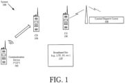
- System 100 comprises a plurality of communication devices 102, 104, 106, a Central Dispatch Center (“CDC") 108, and a broadband site 110.
- the communication devices 102-106 include, but are not limited to, a portable radio (e.g., an LMR), a fixed radio with a static location, a smart phone, and/or a base station.
- the broadband site 110 includes, but is not limited to, an LMR site, a 2G cellular site, a 3G cellular site, a 4G cellular site, and/or a 5G cellular site.
- CDC 108 and broadband site 110 are well known in the art, and therefore will not be described herein.
- signals are communicated between the communication devices 102-106 and/or between one or more communication devices and the CDC 108.
- communication device 102 communicates a signal to communication device 104
- CDC 108 communicates a signal to communication device 106.
- Communication devices 104 and 106 perform operations to mitigate interference caused by the broadband site 110.
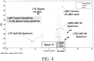
- the interference results because the raised noise floor of received broadband signals (e.g., broadband signal 400 of FIG. 4 ) causes the noise floor of the communication device to be increased when the signal power is above a certain level.
- the manner in which communication devices 104 and 106 mitigate the broadband interference to signals will become evident as the discussion progresses.
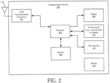
- Communication device 200 can include more or less components than that shown in FIG. 2 in accordance with a given application.
- communication device 200 can include one or both components 208 and 210. The present solution is not limited in this regard.
- the communication device 200 comprises an LMR communication transceiver 202 coupled to an antenna 216.
- the LMR communication transceiver can comprise one or more components such as a processor, an application specific circuit, a programmable logic device, a digital signal processor, or other circuit programmed to perform the functions described herein.
- the communication transceiver 202 can enable end-to-end LMR communication services in a manner known in the art. In this regard, the communication transceiver can facilitate communication of voice data from the communication device 200 over an LMR network.
- the communication device 200 has been described herein as comprising an LMR communication transceiver, it should be understood that the solution is not limited in this regard.
- the communication network can comprise a cellular communication network instead of an LMR type network.
- the communication device 200 could include a cellular network communication transceiver in place of an LMR communication transceiver.
- the communication device 200 could include both an LMR communication transceiver and a cellular network communication transceiver.
- the solutions described herein can be implemented in an LMR communication network, a cellular communication network, and/or any other communication network where broadband interference by another communication system exists that generates interference energy that may be detected in neighboring channels.
- the LMR communication transceiver 202 is connected to a processor 204 comprising an electronic circuit.
- the processor 204 is configured to control the LMR communication transceiver 202 for providing LMR services.
- the processor 204 also facilitates mitigation of interference to signals. The manner in which the processor facilitates interference mitigation will become evident as the discussion progresses.
- a memory 206, display 208, user interface 212 and Input/Output (“I/O") device(s) 210 are also connected to the processor 204.
- the processor 204 may be configured to collect and store data generated by the I/O device(s) 210 and/or external devices (not shown). Data stored in memory 206 can include, but is not limited to, one or more look-up tables or databases which facilitate selection of communication groups or specific communication device.
- the user interface 212 includes, but is not limited to, a plurality of user depressible buttons that may be used, for example, for entering numerical inputs and selecting various functions of the communication device 200. This portion of the user interface may be configured as a keypad. Additional control buttons and/or rotatable knobs may also be provided with the user interface 212.
- a battery 214 or other power source may be provided for powering the components of the communication device 200.
- the battery 200 may comprise a rechargeable and/or replaceable battery. Batteries are well known in the art, and therefore will not be discussed here.
- the communication device architecture shown in FIG. 2 should be understood to be one possible example of a communication device system which can be used in connection with the various implementations disclosed herein.
- the systems and methods disclosed herein are not limited in this regard and any other suitable communication device system architecture can also be used without limitation.
- Applications that can include the apparatus and systems broadly include a variety of electronic and computer systems.
- certain functions can be implemented in two or more specific interconnected hardware modules or devices with related control and data signals communicated between and through the modules, or as portions of an application-specific integrated circuit.
- the illustrative system is applicable to software, firmware, and hardware implementations.
- Receiver 300 comprises a variable attenuator 302, a band selection filter 303, a Low-Noise Amplifier (“LNA”) 304, front end hardware 306, and back end hardware 308.
- LNA Low-Noise Amplifier
- the variable attenuator receives signals from the antenna 216 and applies attenuation to the place the receiver 300 in a more linear operating region.
- the amount of attenuation is controlled by the processor 204 of FIG. 2 .
- the manner in which the attenuation by the variable attenuator 302 is controlled will become evident as the discussion progresses.
- Spectrum 404 represents the relative power of the noise interference that is caused by a spreading of the LTE signal 400 into the LMR band 402. This additional noise that shows up at the receiver's front end degrades the performance of the receiver.
- Spectrum 406 represents the noise interference when both LMR carriers and the LTE signal 400 are present in the LMR band 402. In this case, there is an even higher interference to signals in the receiver band. This apparent noise exists because of a limitation in a performance of the receiver.
- the noise floor drops rapidly. For example, if 1 dB of attenuation is added in the receiver, then the noise floor decreases by 3 dB if the interference is domination by 3 rd order intermodulation products. Thus, an advantage is obtained by attenuating the signal because the interference generated by intermodulation is more attenuated.
- FIG. 5 there is provided a graph showing a current performance of an LMR receiver when no attenuation is applied prior to its front end hardware.
- the current performance is represented by line 500.
- Line 500 has a slope of 3:1. The slope is defined as the change in noise power over the change in attenuation (i.e., ⁇ noise power/ ⁇ attenuation).
- the 3:1 slope is due to the 3 rd order IM products caused by an LTE site's signal level placing the communication device receiver in a non-linear operating region.
- Line 502 represents the desired performance of the LMR receiver with an optimal amount of attenuation added to its front end.
- Line 502 has a slope of 1:1, which indicates that the LMR receiver is operating in a more linear operating region.
- Line 504 represents the LMR receiver performance when a 6 dB attenuation is applied to its front end. As can be seen, there is a 12 dB improvement in LMR receiver performance when the 6 dB attenuation is applied to its front end. Line 506 represent the LMR receiver performance when a 12 dB attenuation is applied. As can be seen, there is an 18 dB improvement in LMR receiver performance when the 12 dB attenuation is applied to its front end.
- the attenuation should not be continuously applied at the receiver front end to mitigate the LTE interference because some sensitivity of the receiver would be lost during times when the IM condition does not exit. So, the present solution waits until the measured slope p is less than the threshold parameter Y.
- Method 600 begins with 602 and continues with 604 where a communication device (e.g., communication device 104 or 106 of FIG. 1 ) performs operations to continuously monitor a communications channel. Methods for monitoring communications channels are well known in the art, and therefore will not be described herein.
- the communication device also receives noise signals and/or communications signals in 604. Methods for receiving noise signals and communications signals are well known in the art, and therefore will not be described herein.
- the noise floor level of the communication device is used to detect when the communication device is under the influence of IM interference or in an IM limited condition. The manner in which the noise floor level is used here will become more evident as the discussion progresses.
- an optimal level of attenuation that is to be applied by a variable attenuator e.g., variable attenuator 302 of FIG. 3
- the amount of attenuation being applied by the variable attenuator is selectively adjusted based on the optimal level of attenuation. For example, the level of attenuation being applied by the variable attenuator is set equal to the optimal level of attenuation.
- 612 is performed where method 600 ends or other processing is performed (e.g., return to 602).
- Method 700 includes operations 702-724 to determine when a communication device is in an environment where the performance is limited by IM products and not thermal noise regardless of what the measured on-channel and adjacent channel powers are. This determination is made based on an estimate noise floor of the communication device's receiver.
- operations in box 750 are performed to detect when there is a high level of interference.
- Operations in box 752 are performed to determine if the inference is due to IM and to change the attenuation to the optimal level to mitigate the IM. All or some of the operations 702-724 can be performed by a communication transceiver (e.g., LMR communication transceiver 202 of FIG. 2 ) and/or a processor (e.g., processor 204 of FIG. 2 ) of a communication device (e.g., communication device 102-106 of FIG. 1 , or communication device 200 of FIG. 2 ).
- a communication transceiver e.g., LMR communication transceiver 202 of FIG. 2
- a processor
- method 700 begins with 702 and continues with 704 where a communication device (e.g., communication device 104 or 106 of FIG. 1 ) performs operations to continuously monitor a communications channel.
- a communication device e.g., communication device 104 or 106 of FIG. 1
- the communication device also receives noise signals and/or communications signals in 704. Methods for receiving noise signals and communications signals are well known in the art, and therefore will not be described herein.
- the communication device estimates a noise floor k with an original attenuation level (e.g., zero) being applied by a variable attenuator (e.g., variable attenuator 302 of FIG. 3 ) of the communication device's receiver (e.g., receiver 300 of FIG. 3 ).
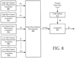
- the noise floor estimation is achieved in accordance with a process shown in FIG. 8 .
- the process begins by acquiring a measurement of an on channel power P 0 in 802, at least one measurement of a high side channel power P +1 , ..., P +Q as shown by 804-806, and at least one measurement of a low side channel power P - 1 , ..., P -W as shown by 808-810.
- the power measurements are then used in 808 to determine a noise floor estimate k .
- the noise floor estimate A may by example be set equal to the minimum acquired power measurement value P min .
- the noise floor estimate k is compared to a threshold value thr in 812.
- the threshold value thr is equal to a thermal noise floor level (which depends on the channel bandwidth the noise measurement is performed over) plus X dB.
- the level X is the amount of degradation that is allowed before the attenuation test for the existence of IM is performed and will vary with specific applications and equipment properties
- a chart is provided that shows that a high side channel in box 900 is an interfering adjacent channel, the on channel in box 902 has a low signal (e.g., due to being far away), and the low channel in box 904 has the smallest power level.
- the noise floor estimate k is set equal to the power level of the low channel since it is the minimal power level of the three channels. The present solution is not limited to the particulars of this scenario.
- the noise floor estimate k is greater than the threshold value thr, then an assumption is made that the signal is in a non-linear region of the receiver and is generating IM (e.g., has at least a 3:1 slope).
- a test is performed in method 700 to determine if an increased amount of attenuation (e.g., 1 dB) improves the communication device's receiver sensitivity, i.e., whether the noise floor level estimate is decreased more than Y times the amount of the added attenuation.
- the result R is used in 708 to determine whether the estimate noise floor k has increased a certain amount above the threshold thr. If not [708:NO], then method 700 returns to 706. If so [708:YES], then method 700 continues with 710.
- an amount of attenuation applied by the variable attenuator (e.g., variable attenuator 302 of FIG. 3 ) of the communication device's receiver (e.g., receiver 300 of FIG. 3 ) is changed by a given amount (e.g., > 1 dB) to improve the communication device's sensitivity.
- Typical 3 rd order IM products have a 3 x increase in the noise level for a 1 x increase in the signal level.
- Typical 5 th order IM products have a 5 x increase in the noise level for a 1 x increase in the signal level.
- a new noise floor level k ' of the communication device is estimated with added attenuation. 712 can also involve measuring the difference between the new noise floor level k' and the previous noise floor level k.
- method 700 continues with 716.
- a slope p of the signal is calculated. Methods for computing the slope p of the signal are well known in the art, and therefore will not be described herein. Still, it should be understood that the slope p is the change in noise power over the change in attenuation. If the slope p is less than Y [718:YES], then method 700 returns to 706 as shown by 720.
- Y is an integer (e.g., 1, 2, etc.). Accordingly, 722 is performed where the attenuation is set for the signal to the previous level of attenuation (e.g., ⁇ ( k- 1), i.e., the original attenuation level plus a total amount of added attenuation) to benefit the sensitivity of the receiver. Subsequently, 724 is performed where method 700 ends or other processing is performed (e.g., return to 702).
- the previous level of attenuation e.g., ⁇ ( k- 1), i.e., the original attenuation level plus a total amount of added attenuation
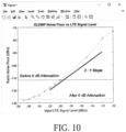
- FIG. 10 there is a graph showing results from operating an LMR receiver in accordance with the above described method for mitigating LTE interference.
- an 18 dB noise floor reduction is provided when 6 dB of attenuation to the LMR receiver's front end. This 18 dB noise floor reduction results in an improvement in the LMR receiver's sensitivity.
Landscapes
- Engineering & Computer Science (AREA)
- Computer Networks & Wireless Communication (AREA)
- Signal Processing (AREA)
- Quality & Reliability (AREA)
- Physics & Mathematics (AREA)
- Electromagnetism (AREA)
- Noise Elimination (AREA)
Claims (9)
- Ein Verfahren zum Betreiben eines Kommunikationsgeräts, um Intermodulationsinterferenzen eines Signals zu vermindern, umfassend:kontinuierliches Überwachen einer Vielzahl von Kommunikationskanälen durch die Kommunikationsvorrichtung (200);Verwenden einer Schätzung des Rauschpegels der Kommunikationsvorrichtung (200), um zu erkennen, wann die Kommunikationsvorrichtung (200) unter dem Einfluss einer hohen Interferenz steht;Bestimmen eines optimalen Dämpfungspegels, der von einem variablen Dämpfungsglied (302) des Empfängers (300) der Kommunikationsvorrichtung anzuwenden ist, um den Einfluss von Intermodulationsinterferenzen aufgrund eines Interferenzsignals zu vermindern; undselektives Einstellen eines Dämpfungsbetrags, der von dem variablen Dämpfungsglied (302) angewendet wird, um den optimalen Dämpfungspegel zu erreichen;wobei der optimale Dämpfungsgrad bestimmt wird durch:Durchführen von Dämpfungsadditionsoperationen durch das variable Dämpfungsglied (302), um iterativ einen inkrementellen Dämpfungsbetrag hinzuzufügen; undMessen einer Geräuschpegel-Differenz zwischen einem Geräuschpegel einer aktuellen Iteration der Dämpfungs-Addier-Operationen und einem Grundgeräuschpegel einer vorherigen Iteration der Dämpfungs-Addier-Operationen, dadurch gekennzeichnet, dass der optimale Dämpfungspegel ferner bestimmt wird durch:Berechnen einer Steigung des Signals, wobei die Steigung durch die Änderung der Rauschleistung gegenüber einer Änderung der Dämpfung definiert ist;Vergleichen der Steigung mit einem Schwellenwert Y; undwobei der optimale Dämpfungsgrad als ein vorheriger Dämpfungsgrad angesehen wird, der von dem variablen Dämpfungsglied (302) angewendet wird, wenn die Steigung unter dem Schwellenwert Y liegt.
- Das Verfahren nach Anspruch 1, das ferner das Schätzen des Grundrauschpegels mit einem ursprünglichen Dämpfungspegel umfasst, der von dem variablen Dämpfungsglied (302) des Empfängers (300) des Kommunikationsgeräts angewendet wird.
- Das Verfahren nach Anspruch 2, wobei der Grundrauschpegel durch Erfassen eines Leistungsmesswerts für einen Ein-Kanal, eines Leistungsmesswerts für mindestens einen High-Side-Kanal und eines Leistungsmesswerts für mindestens einen Low-Side-Kanal geschätzt wird.
- Das Verfahren nach Anspruch 3, bei dem eine gleiche Anzahl von Messungen der hohen Kanalleistung und der niedrigen Kanalleistung durchgeführt wird.
- Das Verfahren nach Anspruch 3, wobei der Grundrauschpegel gleich einem Minimalwert der Leistungsmesswerte gesetzt wird, die für den Ein-Kanal, den mindestens einen High-Side-Kanal und den mindestens einen High-Side-Kanal erfasst wurden.
- Das Verfahren nach Anspruch 1, wobei eine Erkennung, wann das Kommunikationsgerät (200) unter dem Einfluss eines hohen Interferenzpegels steht, auf der Grundlage von Ergebnissen aus dem Vergleich des geschätzten Rauschpegels mit einem Schwellenwert erfolgt.
- Das Verfahren nach Anspruch 6, das ferner einen Schritt der Durchführung eines Tests umfasst, um festzustellen, ob die Störung auf Intermodulation zurückzuführen ist und die Empfängerempfindlichkeit durch Hinzufügen einer gewissen Dämpfung vor einem rauscharmen Verstärker verbessert werden kann, um den Empfänger in einen lineareren Betriebsbereich zu bringen, und Einstellen des Schwellenwerts auf einen bekannten thermischen Rauschpegel-Boden plus einen bestimmten Betrag X, wobei X den Betrag des Anstiegs des Rauschbodens darstellt, der zulässig ist, bevor der Test durchgeführt wird.
- Das Verfahren nach Anspruch 3, wobei eine unterschiedliche Anzahl von Messungen der hohen Kanalleistung und der niedrigen Kanalleistung erfasst wird.
- Ein System (100), das eine Kommunikationsvorrichtung (200) umfasst, die Folgendes umfasst:einen Prozessor (204);einen Empfänger (300), wobei der Empfänger ein variables Dämpfungsglied (302) umfasst;ein nicht-transitorisches, computerlesbares Speichermedium (206), das Programmieranweisungen umfasst, die so konfiguriert sind, dass sie den Prozessor veranlassen, ein Verfahren zum Betreiben der Kommunikationsvorrichtung (200) zu implementieren, um Intermodulationsstörungen eines Signals zu vermindern, wobei die Programmieranweisungen Anweisungen umfassen, um:die Kommunikationsvorrichtung (200) veranlassen, eine Vielzahl von Kommunikationskanälen kontinuierlich zu überwachen;eine Schätzung des Rauschpegels des Kommunikationsgeräts (200) verwenden, um zu erkennen, wann das Kommunikationsgerät (200) unter dem Einfluss einer starken Störung steht;Bestimmen eines optimalen Dämpfungspegels, der von dem variablen Dämpfungsglied (302) des Empfängers (300) der Kommunikationsvorrichtung anzuwenden ist, um den Einfluss von Intermodulationsstörungen aufgrund eines Interferenzsignals zu verringern; undveranlassen, dass ein Dämpfungsbetrag, der von dem variablen Dämpfungsglied (302) angewendet wird, selektiv auf der Grundlage des optimalen Dämpfungspegels eingestellt wird;wobeidas variable Dämpfungsglied (302) geeignet ist, Dämpfungsadditionsoperationen durchzuführen, um iterativ einen inkrementellen Dämpfungsbetrag hinzuzufügen; unddadurch gekennzeichnet, dass die Kommunikationseinrichtung geeignet ist, um
Messen einer Geräuschpegeldifferenz zwischen einem Geräuschpegel einer aktuellen Iteration der Dämpfungsadditionsoperationen und einem Geräuschbodenpegel einer vorhergehenden Iteration der Dämpfungsadditionsoperationen, wobei der optimale Dämpfungspegel ferner bestimmt wird durch:Berechnen einer Steigung des Signals, wobei die Steigung durch die Änderung der Rauschleistung über eine Änderung der Dämpfung definiert ist; undVergleichen der Steigung mit einem Schwellenwert Y; und Betrachten des optimalen Dämpfungsniveaus als ein vorheriges Dämpfungsniveau, das von dem variablen Dämpfungsglied (302) angewendet wird, wenn die Steigung kleiner als der Schwellenwert Y ist, um das optimale Dämpfungsniveau zu bestimmen.
Applications Claiming Priority (1)
| Application Number | Priority Date | Filing Date | Title |
|---|---|---|---|
| US16/510,650 US11018783B2 (en) | 2019-07-12 | 2019-07-12 | System and method for mitigating broadband interference |
Publications (2)
| Publication Number | Publication Date |
|---|---|
| EP3764553A1 EP3764553A1 (de) | 2021-01-13 |
| EP3764553B1 true EP3764553B1 (de) | 2024-12-18 |
Family
ID=71523033
Family Applications (1)
| Application Number | Title | Priority Date | Filing Date |
|---|---|---|---|
| EP20184429.7A Active EP3764553B1 (de) | 2019-07-12 | 2020-07-07 | System und verfahren zur minderung von breitbandinterferenzen |
Country Status (4)
| Country | Link |
|---|---|
| US (1) | US11018783B2 (de) |
| EP (1) | EP3764553B1 (de) |
| AU (1) | AU2020203019B2 (de) |
| CA (1) | CA3084614C (de) |
Families Citing this family (2)
| Publication number | Priority date | Publication date | Assignee | Title |
|---|---|---|---|---|
| US11671134B2 (en) * | 2021-09-15 | 2023-06-06 | Apple Inc. | Wireless circuitry desensitization detection |
| CN114189297B (zh) * | 2021-11-23 | 2024-05-28 | 上海移为通信技术股份有限公司 | 无线通信设备及其干扰检测方法 |
Citations (1)
| Publication number | Priority date | Publication date | Assignee | Title |
|---|---|---|---|---|
| EP1639700B1 (de) * | 2003-06-17 | 2009-09-23 | Motorola, Inc. | Sender mit kartesischer schleife und verfahren zur einstellung eines ausgangspegels eines solchen senders |
Family Cites Families (12)
| Publication number | Priority date | Publication date | Assignee | Title |
|---|---|---|---|---|
| DE3447282A1 (de) * | 1984-12-24 | 1986-07-10 | Telefunken electronic GmbH, 7100 Heilbronn | Funkempfaenger |
| US5201062A (en) * | 1990-03-28 | 1993-04-06 | Pioneer Electronic Corporation | Noise reducing circuit |
| EP0600637A1 (de) * | 1992-12-01 | 1994-06-08 | Hughes Aircraft Company | Verteiltes System zur Verstärkungsregelung in einem digitalen Empfänger |
| US5761614A (en) * | 1996-03-22 | 1998-06-02 | Ericsson Inc. | Automated system and method for optimizing receive system performance |
| US6807405B1 (en) * | 1999-04-28 | 2004-10-19 | Isco International, Inc. | Method and a device for maintaining the performance quality of a code-division multiple access system in the presence of narrow band interference |
| US20040038656A1 (en) * | 2002-08-22 | 2004-02-26 | Mccall John H. | Method and apparatus for distortion reduction and optimizing current consumption via adjusting amplifier linearity |
| US7672359B2 (en) * | 2004-01-28 | 2010-03-02 | Andrew Llc | Spread-spectrum receivers with extended dynamic range |
| US7292830B1 (en) * | 2004-03-31 | 2007-11-06 | Nortel Networks Limited | Receiver gain management |
| US7634277B2 (en) * | 2005-04-28 | 2009-12-15 | Cisco Technology, Inc. | Method for allocating channel resources for improving frequency utilization efficiency of wireless communication systems |
| US9204087B2 (en) | 2011-11-29 | 2015-12-01 | Maxlinear, Inc. | Method and system for interference avoidance in a multiprotocol communication system |
| US9180357B2 (en) * | 2013-06-06 | 2015-11-10 | Zih Corp. | Multiple antenna interference rejection in ultra-wideband real time locating systems |
| US10264462B2 (en) | 2013-06-17 | 2019-04-16 | Marvell World Trade Ltd. | Method and apparatus for mitigating the effect of certain types of interference on a signal received in a wireless network |
-
2019
- 2019-07-12 US US16/510,650 patent/US11018783B2/en active Active
-
2020
- 2020-05-07 AU AU2020203019A patent/AU2020203019B2/en active Active
- 2020-06-22 CA CA3084614A patent/CA3084614C/en active Active
- 2020-07-07 EP EP20184429.7A patent/EP3764553B1/de active Active
Patent Citations (1)
| Publication number | Priority date | Publication date | Assignee | Title |
|---|---|---|---|---|
| EP1639700B1 (de) * | 2003-06-17 | 2009-09-23 | Motorola, Inc. | Sender mit kartesischer schleife und verfahren zur einstellung eines ausgangspegels eines solchen senders |
Also Published As
| Publication number | Publication date |
|---|---|
| CA3084614A1 (en) | 2021-01-12 |
| AU2020203019A1 (en) | 2021-01-28 |
| CA3084614C (en) | 2023-04-11 |
| EP3764553A1 (de) | 2021-01-13 |
| AU2020203019B2 (en) | 2022-06-30 |
| US20210013977A1 (en) | 2021-01-14 |
| US11018783B2 (en) | 2021-05-25 |
Similar Documents
| Publication | Publication Date | Title |
|---|---|---|
| EP1326347B1 (de) | Verfahren und Einrichtung zum Steuern des Dynamikbereichs eines Empfängers | |
| US8583034B2 (en) | Verifying and mitigating oscillation in amplifiers | |
| US8639180B2 (en) | Verifying and mitigating oscillation in amplifiers | |
| KR100699193B1 (ko) | 리버스 링크 오버로드 제어 시스템 및 그 방법 | |
| JP2003244754A (ja) | 基地局及び通信方法 | |
| CA3084614C (en) | System and method for mitigating broadband interference | |
| EP2510630B1 (de) | Lastschätzung in der drahtlosen kommunikation | |
| US9960866B1 (en) | Method and apparatus for signal-to-noise ratio (SNR) estimation | |
| EP2536031A1 (de) | Verfahren und Funkempfänger mit harmonischer Verzerrungserkennung | |
| RU2187890C2 (ru) | Устройство и способ для подавления внешних сигналов радиопомех в мобильном телефоне системы множественного доступа с кодовым разделением каналов | |
| EP3849080B1 (de) | System und verfahren zur optimierung der intermodulationsleistung von empfängern | |
| US7826802B2 (en) | Estimation of received signal strength | |
| CN100514882C (zh) | 在移动通信系统中测量接收信号功率的设备和方法 | |
| US20160128069A1 (en) | De-sense characterization with accurate estimation of tx backoff based on dynamic channel conditions | |
| Laughlin et al. | Tunable Duplexers: Downlink Band Isolation Requirements for LTE User Equipment. | |
| CN101523775B (zh) | 用于改进的噪声基底估计的方法和设备 | |
| US7277500B2 (en) | Signal-processing method and a receiver | |
| CA2845247C (en) | Verifying and mitigating oscillation in amplifiers | |
| US7969939B2 (en) | Measuring signal quality | |
| RU2287900C1 (ru) | Способ измерения многосигнальной избирательности приемника широкополосных сигналов | |
| KR20110067785A (ko) | 광중계기로 인한 노이즈 제거 기능을 갖는 접속노드 장치 및 그 방법 |
Legal Events
| Date | Code | Title | Description |
|---|---|---|---|
| PUAI | Public reference made under article 153(3) epc to a published international application that has entered the european phase |
Free format text: ORIGINAL CODE: 0009012 |
|
| STAA | Information on the status of an ep patent application or granted ep patent |
Free format text: STATUS: REQUEST FOR EXAMINATION WAS MADE |
|
| 17P | Request for examination filed |
Effective date: 20200707 |
|
| AK | Designated contracting states |
Kind code of ref document: A1 Designated state(s): AL AT BE BG CH CY CZ DE DK EE ES FI FR GB GR HR HU IE IS IT LI LT LU LV MC MK MT NL NO PL PT RO RS SE SI SK SM TR |
|
| AX | Request for extension of the european patent |
Extension state: BA ME |
|
| STAA | Information on the status of an ep patent application or granted ep patent |
Free format text: STATUS: EXAMINATION IS IN PROGRESS |
|
| 17Q | First examination report despatched |
Effective date: 20221027 |
|
| GRAP | Despatch of communication of intention to grant a patent |
Free format text: ORIGINAL CODE: EPIDOSNIGR1 |
|
| STAA | Information on the status of an ep patent application or granted ep patent |
Free format text: STATUS: GRANT OF PATENT IS INTENDED |
|
| INTG | Intention to grant announced |
Effective date: 20241004 |
|
| GRAS | Grant fee paid |
Free format text: ORIGINAL CODE: EPIDOSNIGR3 |
|
| GRAA | (expected) grant |
Free format text: ORIGINAL CODE: 0009210 |
|
| STAA | Information on the status of an ep patent application or granted ep patent |
Free format text: STATUS: THE PATENT HAS BEEN GRANTED |
|
| AK | Designated contracting states |
Kind code of ref document: B1 Designated state(s): AL AT BE BG CH CY CZ DE DK EE ES FI FR GB GR HR HU IE IS IT LI LT LU LV MC MK MT NL NO PL PT RO RS SE SI SK SM TR |
|
| P01 | Opt-out of the competence of the unified patent court (upc) registered |
Free format text: CASE NUMBER: APP_60380/2024 Effective date: 20241108 |
|
| REG | Reference to a national code |
Ref country code: CH Ref legal event code: EP |
|
| REG | Reference to a national code |
Ref country code: DE Ref legal event code: R096 Ref document number: 602020043239 Country of ref document: DE |
|
| REG | Reference to a national code |
Ref country code: IE Ref legal event code: FG4D |
|
| REG | Reference to a national code |
Ref country code: LT Ref legal event code: MG9D |
|
| PG25 | Lapsed in a contracting state [announced via postgrant information from national office to epo] |
Ref country code: HR Free format text: LAPSE BECAUSE OF FAILURE TO SUBMIT A TRANSLATION OF THE DESCRIPTION OR TO PAY THE FEE WITHIN THE PRESCRIBED TIME-LIMIT Effective date: 20241218 |
|
| PG25 | Lapsed in a contracting state [announced via postgrant information from national office to epo] |
Ref country code: FI Free format text: LAPSE BECAUSE OF FAILURE TO SUBMIT A TRANSLATION OF THE DESCRIPTION OR TO PAY THE FEE WITHIN THE PRESCRIBED TIME-LIMIT Effective date: 20241218 |
|
| PG25 | Lapsed in a contracting state [announced via postgrant information from national office to epo] |
Ref country code: BG Free format text: LAPSE BECAUSE OF FAILURE TO SUBMIT A TRANSLATION OF THE DESCRIPTION OR TO PAY THE FEE WITHIN THE PRESCRIBED TIME-LIMIT Effective date: 20241218 |
|
| PG25 | Lapsed in a contracting state [announced via postgrant information from national office to epo] |
Ref country code: NO Free format text: LAPSE BECAUSE OF FAILURE TO SUBMIT A TRANSLATION OF THE DESCRIPTION OR TO PAY THE FEE WITHIN THE PRESCRIBED TIME-LIMIT Effective date: 20250318 |
|
| REG | Reference to a national code |
Ref country code: NL Ref legal event code: MP Effective date: 20241218 |
|
| PG25 | Lapsed in a contracting state [announced via postgrant information from national office to epo] |
Ref country code: LV Free format text: LAPSE BECAUSE OF FAILURE TO SUBMIT A TRANSLATION OF THE DESCRIPTION OR TO PAY THE FEE WITHIN THE PRESCRIBED TIME-LIMIT Effective date: 20241218 Ref country code: GR Free format text: LAPSE BECAUSE OF FAILURE TO SUBMIT A TRANSLATION OF THE DESCRIPTION OR TO PAY THE FEE WITHIN THE PRESCRIBED TIME-LIMIT Effective date: 20250319 |
|
| PG25 | Lapsed in a contracting state [announced via postgrant information from national office to epo] |
Ref country code: RS Free format text: LAPSE BECAUSE OF FAILURE TO SUBMIT A TRANSLATION OF THE DESCRIPTION OR TO PAY THE FEE WITHIN THE PRESCRIBED TIME-LIMIT Effective date: 20250318 |
|
| PG25 | Lapsed in a contracting state [announced via postgrant information from national office to epo] |
Ref country code: NL Free format text: LAPSE BECAUSE OF FAILURE TO SUBMIT A TRANSLATION OF THE DESCRIPTION OR TO PAY THE FEE WITHIN THE PRESCRIBED TIME-LIMIT Effective date: 20241218 |
|
| REG | Reference to a national code |
Ref country code: AT Ref legal event code: MK05 Ref document number: 1753079 Country of ref document: AT Kind code of ref document: T Effective date: 20241218 |
|
| PG25 | Lapsed in a contracting state [announced via postgrant information from national office to epo] |
Ref country code: SM Free format text: LAPSE BECAUSE OF FAILURE TO SUBMIT A TRANSLATION OF THE DESCRIPTION OR TO PAY THE FEE WITHIN THE PRESCRIBED TIME-LIMIT Effective date: 20241218 |
|
| PG25 | Lapsed in a contracting state [announced via postgrant information from national office to epo] |
Ref country code: PL Free format text: LAPSE BECAUSE OF FAILURE TO SUBMIT A TRANSLATION OF THE DESCRIPTION OR TO PAY THE FEE WITHIN THE PRESCRIBED TIME-LIMIT Effective date: 20241218 |
|
| PG25 | Lapsed in a contracting state [announced via postgrant information from national office to epo] |
Ref country code: ES Free format text: LAPSE BECAUSE OF FAILURE TO SUBMIT A TRANSLATION OF THE DESCRIPTION OR TO PAY THE FEE WITHIN THE PRESCRIBED TIME-LIMIT Effective date: 20241218 |
|
| PG25 | Lapsed in a contracting state [announced via postgrant information from national office to epo] |
Ref country code: IS Free format text: LAPSE BECAUSE OF FAILURE TO SUBMIT A TRANSLATION OF THE DESCRIPTION OR TO PAY THE FEE WITHIN THE PRESCRIBED TIME-LIMIT Effective date: 20250418 |
|
| PG25 | Lapsed in a contracting state [announced via postgrant information from national office to epo] |
Ref country code: PT Free format text: LAPSE BECAUSE OF FAILURE TO SUBMIT A TRANSLATION OF THE DESCRIPTION OR TO PAY THE FEE WITHIN THE PRESCRIBED TIME-LIMIT Effective date: 20250421 |
|
| PG25 | Lapsed in a contracting state [announced via postgrant information from national office to epo] |
Ref country code: EE Free format text: LAPSE BECAUSE OF FAILURE TO SUBMIT A TRANSLATION OF THE DESCRIPTION OR TO PAY THE FEE WITHIN THE PRESCRIBED TIME-LIMIT Effective date: 20241218 |
|
| PG25 | Lapsed in a contracting state [announced via postgrant information from national office to epo] |
Ref country code: AT Free format text: LAPSE BECAUSE OF FAILURE TO SUBMIT A TRANSLATION OF THE DESCRIPTION OR TO PAY THE FEE WITHIN THE PRESCRIBED TIME-LIMIT Effective date: 20241218 Ref country code: RO Free format text: LAPSE BECAUSE OF FAILURE TO SUBMIT A TRANSLATION OF THE DESCRIPTION OR TO PAY THE FEE WITHIN THE PRESCRIBED TIME-LIMIT Effective date: 20241218 |
|
| PG25 | Lapsed in a contracting state [announced via postgrant information from national office to epo] |
Ref country code: SK Free format text: LAPSE BECAUSE OF FAILURE TO SUBMIT A TRANSLATION OF THE DESCRIPTION OR TO PAY THE FEE WITHIN THE PRESCRIBED TIME-LIMIT Effective date: 20241218 |
|
| PG25 | Lapsed in a contracting state [announced via postgrant information from national office to epo] |
Ref country code: CZ Free format text: LAPSE BECAUSE OF FAILURE TO SUBMIT A TRANSLATION OF THE DESCRIPTION OR TO PAY THE FEE WITHIN THE PRESCRIBED TIME-LIMIT Effective date: 20241218 |
|
| PG25 | Lapsed in a contracting state [announced via postgrant information from national office to epo] |
Ref country code: IT Free format text: LAPSE BECAUSE OF FAILURE TO SUBMIT A TRANSLATION OF THE DESCRIPTION OR TO PAY THE FEE WITHIN THE PRESCRIBED TIME-LIMIT Effective date: 20241218 |
|
| PG25 | Lapsed in a contracting state [announced via postgrant information from national office to epo] |
Ref country code: SE Free format text: LAPSE BECAUSE OF FAILURE TO SUBMIT A TRANSLATION OF THE DESCRIPTION OR TO PAY THE FEE WITHIN THE PRESCRIBED TIME-LIMIT Effective date: 20241218 |
|
| REG | Reference to a national code |
Ref country code: DE Ref legal event code: R097 Ref document number: 602020043239 Country of ref document: DE |
|
| PG25 | Lapsed in a contracting state [announced via postgrant information from national office to epo] |
Ref country code: DK Free format text: LAPSE BECAUSE OF FAILURE TO SUBMIT A TRANSLATION OF THE DESCRIPTION OR TO PAY THE FEE WITHIN THE PRESCRIBED TIME-LIMIT Effective date: 20241218 |
|
| PGFP | Annual fee paid to national office [announced via postgrant information from national office to epo] |
Ref country code: DE Payment date: 20250729 Year of fee payment: 6 |
|
| PGFP | Annual fee paid to national office [announced via postgrant information from national office to epo] |
Ref country code: GB Payment date: 20250728 Year of fee payment: 6 |
|
| PGFP | Annual fee paid to national office [announced via postgrant information from national office to epo] |
Ref country code: FR Payment date: 20250725 Year of fee payment: 6 |
|
| PLBE | No opposition filed within time limit |
Free format text: ORIGINAL CODE: 0009261 |
|
| STAA | Information on the status of an ep patent application or granted ep patent |
Free format text: STATUS: NO OPPOSITION FILED WITHIN TIME LIMIT |
|
| REG | Reference to a national code |
Ref country code: CH Ref legal event code: L10 Free format text: ST27 STATUS EVENT CODE: U-0-0-L10-L00 (AS PROVIDED BY THE NATIONAL OFFICE) Effective date: 20251029 |
|
| 26N | No opposition filed |
Effective date: 20250919 |
|
| REG | Reference to a national code |
Ref country code: CH Ref legal event code: H13 Free format text: ST27 STATUS EVENT CODE: U-0-0-H10-H13 (AS PROVIDED BY THE NATIONAL OFFICE) Effective date: 20260224 |
|
| PG25 | Lapsed in a contracting state [announced via postgrant information from national office to epo] |
Ref country code: LU Free format text: LAPSE BECAUSE OF NON-PAYMENT OF DUE FEES Effective date: 20250707 |
|
| REG | Reference to a national code |
Ref country code: BE Ref legal event code: MM Effective date: 20250731 |
|
| PG25 | Lapsed in a contracting state [announced via postgrant information from national office to epo] |
Ref country code: BE Free format text: LAPSE BECAUSE OF NON-PAYMENT OF DUE FEES Effective date: 20250731 |
|
| PG25 | Lapsed in a contracting state [announced via postgrant information from national office to epo] |
Ref country code: CH Free format text: LAPSE BECAUSE OF NON-PAYMENT OF DUE FEES Effective date: 20250731 |
|
| PG25 | Lapsed in a contracting state [announced via postgrant information from national office to epo] |
Ref country code: LT Free format text: LAPSE BECAUSE OF FAILURE TO SUBMIT A TRANSLATION OF THE DESCRIPTION OR TO PAY THE FEE WITHIN THE PRESCRIBED TIME-LIMIT Effective date: 20241218 |
|
| PG25 | Lapsed in a contracting state [announced via postgrant information from national office to epo] |
Ref country code: IE Free format text: LAPSE BECAUSE OF NON-PAYMENT OF DUE FEES Effective date: 20250707 |
|
| PG25 | Lapsed in a contracting state [announced via postgrant information from national office to epo] |
Ref country code: MC Free format text: LAPSE BECAUSE OF FAILURE TO SUBMIT A TRANSLATION OF THE DESCRIPTION OR TO PAY THE FEE WITHIN THE PRESCRIBED TIME-LIMIT Effective date: 20241218 |
|
| PG25 | Lapsed in a contracting state [announced via postgrant information from national office to epo] |
Ref country code: CY Free format text: LAPSE BECAUSE OF FAILURE TO SUBMIT A TRANSLATION OF THE DESCRIPTION OR TO PAY THE FEE WITHIN THE PRESCRIBED TIME-LIMIT Effective date: 20241218 |