EP3764521A1 - Motorisation electrique pour vehicule automobile et procede d'usinage de carters - Google Patents
Motorisation electrique pour vehicule automobile et procede d'usinage de carters Download PDFInfo
- Publication number
- EP3764521A1 EP3764521A1 EP20178277.8A EP20178277A EP3764521A1 EP 3764521 A1 EP3764521 A1 EP 3764521A1 EP 20178277 A EP20178277 A EP 20178277A EP 3764521 A1 EP3764521 A1 EP 3764521A1
- Authority
- EP
- European Patent Office
- Prior art keywords
- centering
- housing
- electric
- female
- machining
- Prior art date
- Legal status (The legal status is an assumption and is not a legal conclusion. Google has not performed a legal analysis and makes no representation as to the accuracy of the status listed.)
- Granted
Links
Images

Classifications
-
- H—ELECTRICITY
- H02—GENERATION; CONVERSION OR DISTRIBUTION OF ELECTRIC POWER
- H02K—DYNAMO-ELECTRIC MACHINES
- H02K7/00—Arrangements for handling mechanical energy structurally associated with dynamo-electric machines, e.g. structural association with mechanical driving motors or auxiliary dynamo-electric machines
- H02K7/003—Couplings; Details of shafts
-
- H—ELECTRICITY
- H02—GENERATION; CONVERSION OR DISTRIBUTION OF ELECTRIC POWER
- H02K—DYNAMO-ELECTRIC MACHINES
- H02K7/00—Arrangements for handling mechanical energy structurally associated with dynamo-electric machines, e.g. structural association with mechanical driving motors or auxiliary dynamo-electric machines
- H02K7/006—Structural association of a motor or generator with the drive train of a motor vehicle
-
- H—ELECTRICITY
- H02—GENERATION; CONVERSION OR DISTRIBUTION OF ELECTRIC POWER
- H02K—DYNAMO-ELECTRIC MACHINES
- H02K7/00—Arrangements for handling mechanical energy structurally associated with dynamo-electric machines, e.g. structural association with mechanical driving motors or auxiliary dynamo-electric machines
- H02K7/10—Structural association with clutches, brakes, gears, pulleys or mechanical starters
- H02K7/116—Structural association with clutches, brakes, gears, pulleys or mechanical starters with gears
Definitions
- the present invention relates to the field of electric motors for motor vehicles.
- an electric motor comprising an electric traction machine housed in a first housing, the output shaft of which is coupled by a splined connection with an input shaft of a reduction gear housed in a second housing. , requiring mutual centering of the two housings.
- the subject of the invention is also a method of machining electric motor casings comprising an electric traction machine housed in a first casing, the output shaft of which is coupled by a splined connection with an input shaft of a reducer housed in a second housing.
- electric road vehicle engines do not include a cut-off clutch between the output shaft of the traction machine and the input shaft of the transmission. This is most often a simple reducer with a single transmission ratio, so that the two shafts are directly and permanently coupled with each other. This arrangement simplifies the overall architecture of the motorization, but results in a loss of flexibility, for the coupling between the machine and the reduction gear.
- This coupling takes place, for example, between a splined male rotor shaft, on the electrical machine side, which is inserted into a female splined primary shaft, on the gearbox side.
- the reverse is also possible.
- the splines are designed to work on their sides. Their functional role is only to transmit torque. They must in no case serve as a centralizer between the two shafts.
- the centering of the shafts can also be sought by introducing cylindrical pins in the housings.
- the pins 1 are shrunk into the casing 2, at the level of the seam face of the two casings 2, 3. They penetrate into holes of greater diameter in the other casing 3, where they have a centering clearance.
- the centering of the casings by the casing noses is yet another solution, illustrated by the figure 3 .
- Electric machine housing 2 is always on the right.
- the output shaft 4 of the machine is male
- the input shaft of the reducer 5 is female.
- This assembly makes it possible to obtain a centering more precise than the pins of the figure 2 , because the distance between the centering diameter and the axes to be aligned is reduced.
- the present invention aims to guard against this imprecision during the machining of the crankcase noses.
- each of the two casings have a female centering bearing engaged around a common intermediate part.
- the output shaft is coupled by a splined connection with an input shaft of a reduction gear, housed in a second housing.
- the output shaft of the electrical machine is a male shaft, which is inserted into a female input shaft of the reducer.
- the machining of a female cylindrical bearing surface for centering on the other housing, and the machining of a cylindrical bearing surface of greater diameter are carried out in the same passage of the cutter in one of the housings. within the centering range.
- FIG. 1 illustrates a first centering mode
- FIG. 2 illustrates a second centering mode
- FIG. 3 illustrates a third method of centering.
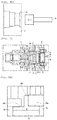
- FIG. 4A shows the machining of the electrical machine housing of the figure 3 .
- FIG. 4B also shows the machining of the electrical machine housing of the figure 3 .
- FIG. 5A is a partial enlargement of the figure 5 .
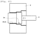
- FIG. 4C illustrates the machining of the electrical machine housing of the figure 5 .
- the output shaft of the electric machine is a male shaft which fits into a female input shaft, of the reducer, but the invention also applies to the reverse arrangement, namely a machine outlet via a female shaft and a reducer inlet via a male shaft.
- the output shaft of the electric machine is a male shaft 4 which is inserted into a female input shaft 5 of the reducer.
- the output shaft of the electrical machine, housed in the first housing, is coupled by a splined connection with the input shaft of the reduction gear, housed in a second housing.
- the electric motor comprises an electric traction machine housed in a first housing 2, the output shaft 4 of which is coupled by a splined connection with an input shaft 5 of a reducer housed in a second housing 3.
- This connection requires the mutual centering of the two housings 2, 3.
- each of the housings 2, 3 has a female centering bearing surface 2c, 3c, engaged around an intermediate support part 10.
- the centering of the two housings 2, 3 is ensured by the engagement of the two female bearing surfaces 2c, 3c on the bearing part 10. Their sealing is ensured by the seals 7, resting on the bearing surfaces 2b, 3b of the housings, which have the same diameter as the centering surfaces 2c, 3c.
- the seals are in the form of lip rings.
- the shaft 4 of the machine 2 is supported by a bearing 6. On the reduction side, we also see a bearing 6, and the parking wheel 8.
- the seal 7 of the electric machine is arranged between the shaft 4 and the surface of centering 2c of the machine housing 2 on the reducer housing 3.
- the seal face 7 of the machine 2 has the same diameter D as its seal face. This diameter is confused with the dynamic seal range of the electric machine. It is much closer to that of trees, than on the figure 3 .
- the centering range of one of the housings (here the machine housing) on the other has the same diameter as its sealing surface.
- the casing of the electrical machine and the casing of the reducer each have a female centering surface 2c, 3c, engaged around the intermediate part 10.
- the centering surface 2c coincides with the surface of the seal 2b .
- its bearing seat 2a has a diameter greater than its centering and seal face 2b, 2c.
- the centering bearing surface 2c of the electric machine casing and that of the gearbox casing 3c are engaged around the intermediate support part 10.
- the intermediate part 10 is a cylindrical part having two male centering surfaces 10a, which may be of the same diameter. They are separated by an annular central stop 10b.
- the part 10 may have a T-section.
- One or both of the female centering staves can be shrunk onto it.
- the advantage of this architecture is that it makes it possible to machine the centering seat 2c at the same time as the rolling seat 2a, that is to say at the same passage of the stepped milling cutter 9, without having to return casing 2.
- the new machining process is illustrated by figure 4C .
- One carries out by the same passage of milling cutter 9 in one of the housings 2, the machining of a cylindrical female centering seat 2 on another housing 3, and the machining of a cylindrical bearing surface 2a of diameter greater than the centering range 2.
- the female centering and sealing seat, and the bearing seat adjacent to it, are machined in the housing of the electrical machine.
- the centering surface 2c of the casing of the electrical machine 2 is machined to the same diameter D as the surface 2b of its seal 7.
- the two surfaces are in continuity with one another.
- the gasket seat 2b of the electric machine is machined in the same tool passage as its centering seat 2c on the reducer housing 3, and as its bearing seat 2a.
- the first advantage of the invention is to improve the centering of the housings, by avoiding the overturning of a housing in the machining range.
- This process simplification makes it possible to improve the positioning accuracy of the bearing seat in relation to the centering seat.
- the new method eliminates the need for a milling pass by simultaneously machining, the bearing seat and the centering surface acting as the seal seat, with a stepped milling cutter.
Landscapes
- Engineering & Computer Science (AREA)
- Power Engineering (AREA)
- General Details Of Gearings (AREA)
- Connection Of Motors, Electrical Generators, Mechanical Devices, And The Like (AREA)
- Manufacture Of Motors, Generators (AREA)
Abstract
Description
- La présente invention se rapporte au domaine des motorisations électriques pour véhicule automobile.
- Plus précisément, elle a pour objet une motorisation électrique, comprenant une machine électrique de traction logée dans un premier carter, dont l'arbre de sortie est accouplé par une liaison cannelée avec un arbre d'entrée d'un réducteur logé dans un deuxième carter, nécessitant le centrage mutuel des deux carters.
- L'invention a également pour objet un procédé d'usinage de carters de motorisation électrique comprenant une machine électrique de traction logée dans un premier carter, dont l'arbre de sortie est accouplé par une liaison cannelée avec un arbre d'entrée d'un réducteur logé dans un deuxième carter.
- A la différence des motorisations thermiques, les motorisations électriques de véhicule routier ne comportent pas d'embrayage de coupure entre l'arbre de sortie de la machine de traction, et l'arbre d'entrée de la transmission. Celle-ci est le plus souvent un simple réducteur à rapport de transmission unique, de sorte que les deux arbres sont accouplés directement et en permanence l'un avec l'autre. Cette disposition simplifie l'architecture globale de la motorisation, mais se traduit par une perte de flexibilité, pour l'accouplement entre la machine et le réducteur.
- Cet accouplement s'effectue par exemple, entre un arbre rotor mâle cannelé, côté machine électrique, qui vient s'insérer dans un arbre primaire cannelé femelle, côté réducteur. L'inverse est également possible. Dans les deux cas, les cannelures sont conçues pour fonctionner sur leurs flancs. Leur rôle fonctionnel est uniquement de transmettre du couple. Elles ne doivent en aucun cas servir de centreur entre les deux arbres.
- Dans ces conditions, l'axialité, des deux arbres ne peut pas être assurée au niveau de leur liaison d'emmanchement. Pour éviter les problèmes de bruyance, de défaillance prématurée des roulements, ou d'usure des cannelures, il est nécessaire de recourir à d'autres moyens pour assurer leur centrage.
- Pour amortir les mouvements radiaux entre les arbres, et supprimer leurs défauts angulaires d'accouplement, on peut introduire une pièce intermédiaire d'accouplement entre les deux arbres. Cette solution est coûteuse, et trop encombrante pour des accouplements de motorisation électrique.
- Le centrage des arbres, peut aussi être recherché en introduisant des pions cylindriques, dans les carters. Dans l'exemple illustré par la
figure 1 , les pions 1 sont frettés dans le carter 2, au niveau de la face de couture des deux carters 2, 3. Ils pénètrent dans des perçages de diamètre supérieur dans l'autre carter 3, où ils disposent d'un jeu de centrage. Ces aménagements sont faciles à réaliser, mais les pions sont toujours éloignés des axes des arbres. Il est difficile de les positionner avec précision par rapport à ces axes, car il faut retourner les carters, entre l'opération d'usinage des logements de pions, et l'opération d'usinage des logements de roulements. - En réalisant des portées de centrage sur les arbres eux-mêmes, comme sur la
figure 2 , on peut aussi améliorer considérablement leur alignement, au risque d'introduire dans la liaison un hyperstatisme générant des problèmes d'usure prématurée des roulements, qui rendent ce type de mesure inapplicable. - Le centrage des carters par les nez de carters, est encore une autre solution, illustrée par la
figure 3 . Le carter de machine électrique 2 est toujours à droite. Sur ce schéma, l'arbre de sortie 4 de la machine est mâle, et l'arbre d'entrée du réducteur 5 est femelle. On voit les roulements 6 de chaque arbre dans son carter, et les bagues à lèvres 7, assurant l'étanchéité des carters. Ce montage permet d'obtenir un centrage plus précis que les pions de lafigure 2 , car la distance entre le diamètre de centrage et les axes à aligner, est réduite. - L'usinage du carter de machine électrique 2 de la
figure 3 avec la fraise 9, s'effectue en deux étapes : - étape 1 (cf.
figure 4A ), usinage de la partie droite du carter (portée de roulement 2a, portée de bague à lèvres 2b, - étape 2 (cf.
figure 4B ), usinage de la portée de centrage 2c, après retournement. - Le retournement du carter sur la machine d'usinage, pose un problème de précision, car la localisation des surfaces issues de la deuxième étape, perdent en précision de localisation (environ 0,055mm selon les tests) par rapport aux surfaces usinées dans la première étape. La présente invention vise à se prémunir de cette imprécision, lors de l'usinage des nez de carter.
- Dans ce but, elle propose que chacun des deux carters présente une portée femelle de centrage engagée autour d'une pièce intermédiaire commune.
- Dans un mode de réalisation préféré de l'invention, l'arbre de sortie est accouplé par une liaison cannelée avec un arbre d'entrée d'un réducteur, logé dans un deuxième carter.
- De préférence, l'arbre de sortie de la machine électrique est un arbre mâle, venant s'insérer dans un arbre d'entrée femelle du réducteur.
- Conformément à l'invention, on effectue en un même passage de fraise dans un des carters, l'usinage d'une portée cylindrique femelle de centrage sur l'autre carter, et l'usinage d'une portée cylindrique de roulement de diamètre supérieur à la portée de centrage. D'autres caractéristiques et avantages de la présente invention ressortiront clairement de la lecture suivante d'un mode de réalisation non limitatif de celle-ci, en se reportant aux dessins annexés.
- [
Fig. 1 ] illustre un premier mode de centrage. - [
Fig. 2 ] illustre un deuxième mode de centrage. - [
Fig. 3 ] illustre un troisième mode de centrage. - [
Fig. 4A ] montre l'usinage du carter de machine électrique de lafigure 3 . - [
Fig. 4B ] montre aussi l'usinage du carter de machine électrique de lafigure 3 . - [
Fig. 5 ] illustre l'invention. - [
Fig. 5A ] est un agrandissement partiel de lafigure 5 . - [
Fig. 4C ] illustre l'usinage du carter de machine électrique de lafigure 5 . - Sur la
figure 5 , on retrouve à droite la machine électrique avec son carter 2 et son arbre de sortie mâle 4, et à gauche le réducteur avec son carter 3 et son arbre primaire (arbre d'entrée) femelle 5. Dans l'exemple décrit, l'arbre de sortie de la machine électrique est un arbre mâle venant s'insérer dans un arbre d'entrée femelle, du réducteur, mais l'invention s'applique également à la disposition inverse, à savoir une sortie de machine par un arbre femelle et une entrée de réducteur par un arbre mâle. - Dans cet exemple non limitatif, l'arbre de sortie de la machine électrique est un arbre mâle 4 venant s'insérer dans un arbre d'entrée femelle 5 du réducteur. L'arbre de sortie de la machine électrique, logé dans le premier carter, est accouplé par une liaison cannelée avec l'arbre d'entrée du réducteur, logé dans un deuxième carter.
- La motorisation électrique comprend une machine électrique de traction logée dans un premier carter 2, dont l'arbre de sortie 4 est accouplé par une liaison cannelée avec un arbre d'entrée 5 d'un réducteur logé dans un deuxième carter 3. Cette liaison nécessite le centrage mutuel des deux carters 2, 3. Conformément à l'invention, chacun des carters 2, 3 présente une portée femelle de centrage 2c, 3c, engagée autour d'une pièce intermédiaire d'appui 10.
- Le centrage des deux carters 2, 3, est assuré par l'engagement des deux portées femelles 2c, 3c sur la pièce d'appui 10. Leur étanchéité est assurée par les joints 7, reposant sur des portées 2b, 3b des carters, qui ont le même diamètre que les portées de centrage 2c, 3c. Les joints se présentent sous la forme de bagues à lèvres. L'arbre 4 de la machine 2 est supporté par un roulement 6. Côté réducteur, on voit aussi un roulement 6, et la roue de parking 8. Le joint 7 de la machine électrique est disposé entre l'arbre 4 et la surface de centrage 2c du carter de machine 2 sur le carter de réducteur 3. La portée de joint 7 de la machine 2, a le même diamètre D que sa portée de joint. Ce diamètre est confondu avec la portée de joint dynamique de la machine électrique . Il est beaucoup plus proche de celui des arbres, que sur la
figure 3 . Conformément à l'invention, la portée de centrage d'un des carters (ici le carter de machine) sur l'autre, a le même diamètre que sa portée de joint d'étanchéité. - Le carter de la machine électrique et le carter du réducteur, présentent chacun une portée de centrage femelle 2c, 3c, engagée autour de la pièce intermédiaire 10. Sur le carter du réducteur, la portée de centrage 2c est confondue avec la portée du joint 2b. En revanche, sa portée de roulement 2a a un diamètre supérieur à sa portée de centrage et de joint 2b, 2c. La portée de centrage 2c du carter de machine électrique et celle du carter du réducteur 3c, sont engagées autour de la pièce d'appui intermédiaire 10.
- La pièce intermédiaire 10 est une pièce cylindrique présentant deux portées mâles de centrage 10a, qui peuvent être de même diamètre. Elles sont séparées par une butée centrale annulaire 10b. La pièce 10 peut présenter une section en T. L'une ou les deux portées femelles de centrage, peuvent être frettées sur celle-ci. L'avantage de cette architecture, est qu'elle permet d'usiner la portée de centrage 2c en même temps que la portée de roulement 2a, c'est-à-dire au même passage de la fraise étagée 9, sans avoir à retourner le carter 2. Le nouveau procédé d'usinage est illustré par la
figure 4C . On effectue par un même passage de fraise 9 dans un des carters 2, l'usinage d'une portée cylindrique femelle de centrage 2 sur un autre carter 3, et l'usinage d'une portée cylindrique de roulement 2a de diamètre supérieur à la portée de centrage 2. - La portée femelle de centrage et d'étanchéité, et la portée de roulement adjacente à celle-ci, sont usinées dans le carter de la machine électrique. La portée de centrage 2c du carter de la machine électrique 2 est usinée au même diamètre D que la portée 2b de son joint d'étanchéité 7. Les deux portées sont dans la continuité l'une de l'autre. La portée de joint 2b de la machine électrique est usinée dans le même passage d'outil que sa portée de centrage 2c sur le carter de réducteur 3, et que sa portée de roulement 2a.
- La localisation relative de ces deux portées est assurée avec une précision correspondant aux préconisations, d'environ 0,02mm, sans subir les dispersions imposées par le retournement du carter. Enfin la nouvelle localisation de la portée de centrage et de joint, convient parfaitement pour le bon fonctionnement d'une bague à lèvre.
- Le bénéfice de l'invention, peut être mis en évidence à partir de calculs de chaînes de cotes sur les carters. On constate ainsi que la nouvelle architecture permet de diviser par cinq le risque d'interférences entre les cannelures des arbres accouplés, par rapport à ces architectures plus classiques, telles que celle de la
figure 1 . - En conclusion, le premier avantage de l'invention est d'améliorer le centrage des carters, en évitant le retournement d'un carter dans la gamme d'usinage. Cette simplification de process, permet d'améliorer la précision de positionnement de la portée de roulements par rapport à la portée de centrage. La nouvelle méthode permet de supprimer un passage de fraise, en usinant simultanément, la portée de roulement et la surface de centrage faisant office de portée de joint, avec une fraise étagée.
Claims (10)
- Motorisation électrique pour véhicule automobile, comprenant une machine électrique de traction logée dans un premier carter (2), dont l'arbre de sortie (4) est accouplé par une liaison cannelée avec un arbre d'entrée (5) d'un réducteur logé dans un deuxième carter nécessitant le centrage mutuel des deux carters (3), caractérisée en ce que chacun des carters présente une portée femelle de centrage (2c, 3c) engagée autour d'une pièce d'appui commune (10) présentant deux portées mâles (10a) de centrage, de même diamètre, séparées par une butée centrale annulaire (10b).
- Motorisation électrique selon la revendication 1, caractérisée en ce que l'arbre de sortie (4) de la machine électrique, est accouplé par une liaison cannelée avec un arbre d'entrée (5) d'un réducteur logé dans le deuxième carter (3).
- Motorisation selon la revendication 1 ou 2, caractérisée en ce que l'étanchéité du réducteur et de la machine électrique est assurée par des joints (7) reposant sur des portées (2b, 3b,) des carters, de même diamètre que leurs portées de centrage(2c, 3c).
- Motorisation électrique selon la revendication 2 ou 3, caractérisé en ce que le carter de machine électrique (2) et le carter (3) du réducteur, présentent chacun une portée de centrage (2c, 3c) femelle emmanchée sur la pièce intermédiaire d'appui (10).
- Motorisation électrique selon l'une des revendications 1 à 4, caractérisée en ce que la pièce intermédiaire (10) a une section en T.
- Motorisation électrique selon l'une des revendications 4, ou 5, caractérisée en ce que l'une des deux portées femelles de centrage est frettée sur la pièce intermédiaire.
- Motorisation selon l'une des revendications 4, 5 ou 6, caractérisée en ce que les deux portées femelles sont frettées sur la pièce intermédiaire (10).
- Procédé d'usinage de carters (2) d'une motorisation électrique comprenant une machine électrique de traction logée dans un premier carter (2), dont l'arbre de sortie (4) est accouplé par une liaison cannelée avec un arbre d'entrée (5) d'un réducteur logé dans un deuxième carter (3), dans lequel on effectue dans un des carters (2), l'usinage d'une portée cylindrique femelle de centrage (2c) sur un autre carter (3), et l'usinage d'une portée cylindrique de roulement (2a) de diamètre supérieur à la portée de centrage (2c), caractérisé en ce que la portée de centrage (2c) du carter de la machine électrique (2) est usinée au même diamètre (D) que la portée (2b) de son joint d'étanchéité (7).
- Procédé d'usinage selon la revendication 8, caractérisé en ce qu'on usine dans le carter (2) de la machine électrique, une portée cylindrique femelle de centrage et de portée de joint (2b, 2c) sur le carter du réducteur (3), et une portée de roulement (2a) adjacente à la portée de joint et de centrage (2b, 2c).
- Procédé d'usinage selon la revendication 8 ou 9, caractérisé en ce que la portée de joint (2b) de la machine électrique est usinée dans le même passage d'outil que sa portée de centrage (2c) sur le carter de réducteur (3) et sa portée de roulement (2a).
Applications Claiming Priority (1)
| Application Number | Priority Date | Filing Date | Title |
|---|---|---|---|
| FR1907850A FR3098453B1 (fr) | 2019-07-12 | 2019-07-12 | Motorisation electrique pour vehicule automobile et procede d’usinage de carters |
Publications (2)
| Publication Number | Publication Date |
|---|---|
| EP3764521A1 true EP3764521A1 (fr) | 2021-01-13 |
| EP3764521B1 EP3764521B1 (fr) | 2023-11-22 |
Family
ID=69024292
Family Applications (1)
| Application Number | Title | Priority Date | Filing Date |
|---|---|---|---|
| EP20178277.8A Active EP3764521B1 (fr) | 2019-07-12 | 2020-06-04 | Motorisation electrique pour vehicule automobile et procede d'usinage de carters |
Country Status (2)
| Country | Link |
|---|---|
| EP (1) | EP3764521B1 (fr) |
| FR (1) | FR3098453B1 (fr) |
Citations (5)
| Publication number | Priority date | Publication date | Assignee | Title |
|---|---|---|---|---|
| US5126609A (en) * | 1990-07-20 | 1992-06-30 | Mitsubishi Denki K. K. | Speed reduction motor with integral hermetic gear case |
| EP1437531A2 (fr) * | 2003-01-13 | 2004-07-14 | Tecnoingranaggi Riduttori S.r.l. | Procédée de fabrication d'un boítier de réducteur de vitesse, en particulier un réducteur de vitesse épicyclique et boítier correspondant |
| US20120060358A1 (en) * | 2003-11-13 | 2012-03-15 | Josef Schmidt | Compact Drive, Spiroid Gear Unit, and Method for Manufacturing a Drive Unit |
| EP2782241A1 (fr) * | 2011-11-18 | 2014-09-24 | NTN Corporation | Dispositif de commande de moteur pour une automobile électrique |
| WO2016156272A1 (fr) * | 2015-03-30 | 2016-10-06 | Moteurs Leroy-Somer | Liaison entre un arbre de machine électrique et un réducteur |
-
2019
- 2019-07-12 FR FR1907850A patent/FR3098453B1/fr not_active Expired - Fee Related
-
2020
- 2020-06-04 EP EP20178277.8A patent/EP3764521B1/fr active Active
Patent Citations (5)
| Publication number | Priority date | Publication date | Assignee | Title |
|---|---|---|---|---|
| US5126609A (en) * | 1990-07-20 | 1992-06-30 | Mitsubishi Denki K. K. | Speed reduction motor with integral hermetic gear case |
| EP1437531A2 (fr) * | 2003-01-13 | 2004-07-14 | Tecnoingranaggi Riduttori S.r.l. | Procédée de fabrication d'un boítier de réducteur de vitesse, en particulier un réducteur de vitesse épicyclique et boítier correspondant |
| US20120060358A1 (en) * | 2003-11-13 | 2012-03-15 | Josef Schmidt | Compact Drive, Spiroid Gear Unit, and Method for Manufacturing a Drive Unit |
| EP2782241A1 (fr) * | 2011-11-18 | 2014-09-24 | NTN Corporation | Dispositif de commande de moteur pour une automobile électrique |
| WO2016156272A1 (fr) * | 2015-03-30 | 2016-10-06 | Moteurs Leroy-Somer | Liaison entre un arbre de machine électrique et un réducteur |
Also Published As
| Publication number | Publication date |
|---|---|
| FR3098453A1 (fr) | 2021-01-15 |
| EP3764521B1 (fr) | 2023-11-22 |
| FR3098453B1 (fr) | 2021-07-02 |
Similar Documents
| Publication | Publication Date | Title |
|---|---|---|
| US20200247236A1 (en) | Torque Transmission Apparatus and a Collar | |
| EP1591694A2 (fr) | Montage d'une boíte de différentiel | |
| CN109311517B (zh) | 履带滚轮组件和方法 | |
| CN106166947A (zh) | 具有锥形花键安排的车桥组件 | |
| US9562603B2 (en) | Drive assembly with a rotating housing attached to an output interface | |
| WO2011125761A1 (fr) | Dispositif de galet de roulement | |
| EP3201492B1 (fr) | Réducteur de vitesse à deux lignes intermédiaires de transmission | |
| FR2932221A1 (fr) | Tourillon support de palier et ensemble d'un tel tourillon et d'un fourreau d'etancheite | |
| FR3049323A1 (fr) | "couronne de differentiel equipee d'une cible de mesure de sa vitesse de rotation et agencement dans une boite de vitesses" | |
| WO2016177549A1 (fr) | Ensemble electromecanique comportant une machine electrique couplee a un reducteur | |
| WO2023016763A1 (fr) | Accouplement d'arbres rotatifs permettant un déplacement axial au moyen d'éléments roulants | |
| FR3006711A1 (fr) | Systeme d'entrainement de pompe a eau et procede de montage | |
| US7302873B2 (en) | Angle drive with power distribution | |
| EP3764521B1 (fr) | Motorisation electrique pour vehicule automobile et procede d'usinage de carters | |
| US9638310B2 (en) | Drive assembly with a rotating housing attached to an output interface | |
| EP3713055A1 (fr) | Motorisation electrique et procede d'usinage de carter | |
| EP3362706B1 (fr) | Couronne dentée pour réducteur épicycloïdal | |
| EP3784901B1 (fr) | Agencement hydraulique pour une roue directrice d'un vehicule | |
| US6036077A (en) | Friction welded shaft | |
| US9074677B2 (en) | Carrier assembly with threaded adjustment member | |
| EP3134286B1 (fr) | Ensemble d'entraînement pour un arbre moteur d'un véhicule automobile | |
| JP2002181139A (ja) | 減速機の出力フランジ構造 | |
| EP3081390B1 (fr) | Système d'entraînement en rotation d'une roue de véhicule automobile | |
| JPH07298547A (ja) | 変速機と電動機の結合構造 | |
| JP7498609B2 (ja) | 変速機付モータ |
Legal Events
| Date | Code | Title | Description |
|---|---|---|---|
| PUAI | Public reference made under article 153(3) epc to a published international application that has entered the european phase |
Free format text: ORIGINAL CODE: 0009012 |
|
| STAA | Information on the status of an ep patent application or granted ep patent |
Free format text: STATUS: THE APPLICATION HAS BEEN PUBLISHED |
|
| AK | Designated contracting states |
Kind code of ref document: A1 Designated state(s): AL AT BE BG CH CY CZ DE DK EE ES FI FR GB GR HR HU IE IS IT LI LT LU LV MC MK MT NL NO PL PT RO RS SE SI SK SM TR |
|
| AX | Request for extension of the european patent |
Extension state: BA ME |
|
| STAA | Information on the status of an ep patent application or granted ep patent |
Free format text: STATUS: REQUEST FOR EXAMINATION WAS MADE |
|
| 17P | Request for examination filed |
Effective date: 20210629 |
|
| RBV | Designated contracting states (corrected) |
Designated state(s): AL AT BE BG CH CY CZ DE DK EE ES FI FR GB GR HR HU IE IS IT LI LT LU LV MC MK MT NL NO PL PT RO RS SE SI SK SM TR |
|
| RAP3 | Party data changed (applicant data changed or rights of an application transferred) |
Owner name: RENAULT S.A.S |
|
| RAP3 | Party data changed (applicant data changed or rights of an application transferred) |
Owner name: RENAULT S.A.S |
|
| RIC1 | Information provided on ipc code assigned before grant |
Ipc: H02K 7/116 20060101ALI20230323BHEP Ipc: H02K 7/00 20060101AFI20230323BHEP |
|
| GRAP | Despatch of communication of intention to grant a patent |
Free format text: ORIGINAL CODE: EPIDOSNIGR1 |
|
| STAA | Information on the status of an ep patent application or granted ep patent |
Free format text: STATUS: GRANT OF PATENT IS INTENDED |
|
| INTG | Intention to grant announced |
Effective date: 20230523 |
|
| P01 | Opt-out of the competence of the unified patent court (upc) registered |
Effective date: 20230608 |
|
| GRAS | Grant fee paid |
Free format text: ORIGINAL CODE: EPIDOSNIGR3 |
|
| GRAA | (expected) grant |
Free format text: ORIGINAL CODE: 0009210 |
|
| STAA | Information on the status of an ep patent application or granted ep patent |
Free format text: STATUS: THE PATENT HAS BEEN GRANTED |
|
| AK | Designated contracting states |
Kind code of ref document: B1 Designated state(s): AL AT BE BG CH CY CZ DE DK EE ES FI FR GB GR HR HU IE IS IT LI LT LU LV MC MK MT NL NO PL PT RO RS SE SI SK SM TR |
|
| REG | Reference to a national code |
Ref country code: GB Ref legal event code: FG4D Free format text: NOT ENGLISH |
|
| REG | Reference to a national code |
Ref country code: CH Ref legal event code: EP Ref country code: DE Ref legal event code: R096 Ref document number: 602020021359 Country of ref document: DE |
|
| REG | Reference to a national code |
Ref country code: IE Ref legal event code: FG4D Free format text: LANGUAGE OF EP DOCUMENT: FRENCH |
|
| REG | Reference to a national code |
Ref country code: LT Ref legal event code: MG9D |
|
| REG | Reference to a national code |
Ref country code: NL Ref legal event code: MP Effective date: 20231122 |
|
| PG25 | Lapsed in a contracting state [announced via postgrant information from national office to epo] |
Ref country code: GR Free format text: LAPSE BECAUSE OF FAILURE TO SUBMIT A TRANSLATION OF THE DESCRIPTION OR TO PAY THE FEE WITHIN THE PRESCRIBED TIME-LIMIT Effective date: 20240223 |
|
| PG25 | Lapsed in a contracting state [announced via postgrant information from national office to epo] |
Ref country code: IS Free format text: LAPSE BECAUSE OF FAILURE TO SUBMIT A TRANSLATION OF THE DESCRIPTION OR TO PAY THE FEE WITHIN THE PRESCRIBED TIME-LIMIT Effective date: 20240322 |
|
| RAP2 | Party data changed (patent owner data changed or rights of a patent transferred) |
Owner name: AMPERE SAS |
|
| PG25 | Lapsed in a contracting state [announced via postgrant information from national office to epo] |
Ref country code: LT Free format text: LAPSE BECAUSE OF FAILURE TO SUBMIT A TRANSLATION OF THE DESCRIPTION OR TO PAY THE FEE WITHIN THE PRESCRIBED TIME-LIMIT Effective date: 20231122 |
|
| REG | Reference to a national code |
Ref country code: AT Ref legal event code: MK05 Ref document number: 1634765 Country of ref document: AT Kind code of ref document: T Effective date: 20231122 |
|
| PG25 | Lapsed in a contracting state [announced via postgrant information from national office to epo] |
Ref country code: NL Free format text: LAPSE BECAUSE OF FAILURE TO SUBMIT A TRANSLATION OF THE DESCRIPTION OR TO PAY THE FEE WITHIN THE PRESCRIBED TIME-LIMIT Effective date: 20231122 |
|
| PG25 | Lapsed in a contracting state [announced via postgrant information from national office to epo] |
Ref country code: AT Free format text: LAPSE BECAUSE OF FAILURE TO SUBMIT A TRANSLATION OF THE DESCRIPTION OR TO PAY THE FEE WITHIN THE PRESCRIBED TIME-LIMIT Effective date: 20231122 |
|
| PG25 | Lapsed in a contracting state [announced via postgrant information from national office to epo] |
Ref country code: ES Free format text: LAPSE BECAUSE OF FAILURE TO SUBMIT A TRANSLATION OF THE DESCRIPTION OR TO PAY THE FEE WITHIN THE PRESCRIBED TIME-LIMIT Effective date: 20231122 |
|
| PG25 | Lapsed in a contracting state [announced via postgrant information from national office to epo] |
Ref country code: NL Free format text: LAPSE BECAUSE OF FAILURE TO SUBMIT A TRANSLATION OF THE DESCRIPTION OR TO PAY THE FEE WITHIN THE PRESCRIBED TIME-LIMIT Effective date: 20231122 Ref country code: LT Free format text: LAPSE BECAUSE OF FAILURE TO SUBMIT A TRANSLATION OF THE DESCRIPTION OR TO PAY THE FEE WITHIN THE PRESCRIBED TIME-LIMIT Effective date: 20231122 Ref country code: IS Free format text: LAPSE BECAUSE OF FAILURE TO SUBMIT A TRANSLATION OF THE DESCRIPTION OR TO PAY THE FEE WITHIN THE PRESCRIBED TIME-LIMIT Effective date: 20240322 Ref country code: GR Free format text: LAPSE BECAUSE OF FAILURE TO SUBMIT A TRANSLATION OF THE DESCRIPTION OR TO PAY THE FEE WITHIN THE PRESCRIBED TIME-LIMIT Effective date: 20240223 Ref country code: ES Free format text: LAPSE BECAUSE OF FAILURE TO SUBMIT A TRANSLATION OF THE DESCRIPTION OR TO PAY THE FEE WITHIN THE PRESCRIBED TIME-LIMIT Effective date: 20231122 Ref country code: BG Free format text: LAPSE BECAUSE OF FAILURE TO SUBMIT A TRANSLATION OF THE DESCRIPTION OR TO PAY THE FEE WITHIN THE PRESCRIBED TIME-LIMIT Effective date: 20240222 Ref country code: AT Free format text: LAPSE BECAUSE OF FAILURE TO SUBMIT A TRANSLATION OF THE DESCRIPTION OR TO PAY THE FEE WITHIN THE PRESCRIBED TIME-LIMIT Effective date: 20231122 Ref country code: PT Free format text: LAPSE BECAUSE OF FAILURE TO SUBMIT A TRANSLATION OF THE DESCRIPTION OR TO PAY THE FEE WITHIN THE PRESCRIBED TIME-LIMIT Effective date: 20240322 |
|
| PG25 | Lapsed in a contracting state [announced via postgrant information from national office to epo] |
Ref country code: SE Free format text: LAPSE BECAUSE OF FAILURE TO SUBMIT A TRANSLATION OF THE DESCRIPTION OR TO PAY THE FEE WITHIN THE PRESCRIBED TIME-LIMIT Effective date: 20231122 Ref country code: RS Free format text: LAPSE BECAUSE OF FAILURE TO SUBMIT A TRANSLATION OF THE DESCRIPTION OR TO PAY THE FEE WITHIN THE PRESCRIBED TIME-LIMIT Effective date: 20231122 Ref country code: PL Free format text: LAPSE BECAUSE OF FAILURE TO SUBMIT A TRANSLATION OF THE DESCRIPTION OR TO PAY THE FEE WITHIN THE PRESCRIBED TIME-LIMIT Effective date: 20231122 Ref country code: NO Free format text: LAPSE BECAUSE OF FAILURE TO SUBMIT A TRANSLATION OF THE DESCRIPTION OR TO PAY THE FEE WITHIN THE PRESCRIBED TIME-LIMIT Effective date: 20240222 Ref country code: LV Free format text: LAPSE BECAUSE OF FAILURE TO SUBMIT A TRANSLATION OF THE DESCRIPTION OR TO PAY THE FEE WITHIN THE PRESCRIBED TIME-LIMIT Effective date: 20231122 Ref country code: HR Free format text: LAPSE BECAUSE OF FAILURE TO SUBMIT A TRANSLATION OF THE DESCRIPTION OR TO PAY THE FEE WITHIN THE PRESCRIBED TIME-LIMIT Effective date: 20231122 |
|
| PG25 | Lapsed in a contracting state [announced via postgrant information from national office to epo] |
Ref country code: DK Free format text: LAPSE BECAUSE OF FAILURE TO SUBMIT A TRANSLATION OF THE DESCRIPTION OR TO PAY THE FEE WITHIN THE PRESCRIBED TIME-LIMIT Effective date: 20231122 |
|
| PG25 | Lapsed in a contracting state [announced via postgrant information from national office to epo] |
Ref country code: CZ Free format text: LAPSE BECAUSE OF FAILURE TO SUBMIT A TRANSLATION OF THE DESCRIPTION OR TO PAY THE FEE WITHIN THE PRESCRIBED TIME-LIMIT Effective date: 20231122 |
|
| PG25 | Lapsed in a contracting state [announced via postgrant information from national office to epo] |
Ref country code: SK Free format text: LAPSE BECAUSE OF FAILURE TO SUBMIT A TRANSLATION OF THE DESCRIPTION OR TO PAY THE FEE WITHIN THE PRESCRIBED TIME-LIMIT Effective date: 20231122 |
|
| PG25 | Lapsed in a contracting state [announced via postgrant information from national office to epo] |
Ref country code: SM Free format text: LAPSE BECAUSE OF FAILURE TO SUBMIT A TRANSLATION OF THE DESCRIPTION OR TO PAY THE FEE WITHIN THE PRESCRIBED TIME-LIMIT Effective date: 20231122 Ref country code: SK Free format text: LAPSE BECAUSE OF FAILURE TO SUBMIT A TRANSLATION OF THE DESCRIPTION OR TO PAY THE FEE WITHIN THE PRESCRIBED TIME-LIMIT Effective date: 20231122 Ref country code: RO Free format text: LAPSE BECAUSE OF FAILURE TO SUBMIT A TRANSLATION OF THE DESCRIPTION OR TO PAY THE FEE WITHIN THE PRESCRIBED TIME-LIMIT Effective date: 20231122 Ref country code: IT Free format text: LAPSE BECAUSE OF FAILURE TO SUBMIT A TRANSLATION OF THE DESCRIPTION OR TO PAY THE FEE WITHIN THE PRESCRIBED TIME-LIMIT Effective date: 20231122 Ref country code: EE Free format text: LAPSE BECAUSE OF FAILURE TO SUBMIT A TRANSLATION OF THE DESCRIPTION OR TO PAY THE FEE WITHIN THE PRESCRIBED TIME-LIMIT Effective date: 20231122 Ref country code: DK Free format text: LAPSE BECAUSE OF FAILURE TO SUBMIT A TRANSLATION OF THE DESCRIPTION OR TO PAY THE FEE WITHIN THE PRESCRIBED TIME-LIMIT Effective date: 20231122 Ref country code: CZ Free format text: LAPSE BECAUSE OF FAILURE TO SUBMIT A TRANSLATION OF THE DESCRIPTION OR TO PAY THE FEE WITHIN THE PRESCRIBED TIME-LIMIT Effective date: 20231122 |
|
| REG | Reference to a national code |
Ref country code: DE Ref legal event code: R097 Ref document number: 602020021359 Country of ref document: DE |
|
| PLBE | No opposition filed within time limit |
Free format text: ORIGINAL CODE: 0009261 |
|
| STAA | Information on the status of an ep patent application or granted ep patent |
Free format text: STATUS: NO OPPOSITION FILED WITHIN TIME LIMIT |
|
| PG25 | Lapsed in a contracting state [announced via postgrant information from national office to epo] |
Ref country code: SI Free format text: LAPSE BECAUSE OF FAILURE TO SUBMIT A TRANSLATION OF THE DESCRIPTION OR TO PAY THE FEE WITHIN THE PRESCRIBED TIME-LIMIT Effective date: 20231122 |
|
| 26N | No opposition filed |
Effective date: 20240823 |
|
| PG25 | Lapsed in a contracting state [announced via postgrant information from national office to epo] |
Ref country code: SI Free format text: LAPSE BECAUSE OF FAILURE TO SUBMIT A TRANSLATION OF THE DESCRIPTION OR TO PAY THE FEE WITHIN THE PRESCRIBED TIME-LIMIT Effective date: 20231122 |
|
| PG25 | Lapsed in a contracting state [announced via postgrant information from national office to epo] |
Ref country code: MC Free format text: LAPSE BECAUSE OF FAILURE TO SUBMIT A TRANSLATION OF THE DESCRIPTION OR TO PAY THE FEE WITHIN THE PRESCRIBED TIME-LIMIT Effective date: 20231122 |
|
| REG | Reference to a national code |
Ref country code: CH Ref legal event code: PL |
|
| PG25 | Lapsed in a contracting state [announced via postgrant information from national office to epo] |
Ref country code: LU Free format text: LAPSE BECAUSE OF NON-PAYMENT OF DUE FEES Effective date: 20240604 |
|
| PG25 | Lapsed in a contracting state [announced via postgrant information from national office to epo] |
Ref country code: IE Free format text: LAPSE BECAUSE OF NON-PAYMENT OF DUE FEES Effective date: 20240604 |
|
| PG25 | Lapsed in a contracting state [announced via postgrant information from national office to epo] |
Ref country code: CH Free format text: LAPSE BECAUSE OF NON-PAYMENT OF DUE FEES Effective date: 20240630 Ref country code: BE Free format text: LAPSE BECAUSE OF NON-PAYMENT OF DUE FEES Effective date: 20240630 |
|
| REG | Reference to a national code |
Ref country code: BE Ref legal event code: MM Effective date: 20240630 |
|
| PGFP | Annual fee paid to national office [announced via postgrant information from national office to epo] |
Ref country code: DE Payment date: 20250618 Year of fee payment: 6 |
|
| PGFP | Annual fee paid to national office [announced via postgrant information from national office to epo] |
Ref country code: GB Payment date: 20250618 Year of fee payment: 6 |
|
| PGFP | Annual fee paid to national office [announced via postgrant information from national office to epo] |
Ref country code: FR Payment date: 20250626 Year of fee payment: 6 |
|
| PG25 | Lapsed in a contracting state [announced via postgrant information from national office to epo] |
Ref country code: FI Free format text: LAPSE BECAUSE OF FAILURE TO SUBMIT A TRANSLATION OF THE DESCRIPTION OR TO PAY THE FEE WITHIN THE PRESCRIBED TIME-LIMIT Effective date: 20231122 |
|
| PG25 | Lapsed in a contracting state [announced via postgrant information from national office to epo] |
Ref country code: CY Free format text: LAPSE BECAUSE OF FAILURE TO SUBMIT A TRANSLATION OF THE DESCRIPTION OR TO PAY THE FEE WITHIN THE PRESCRIBED TIME-LIMIT; INVALID AB INITIO Effective date: 20200604 |
|
| PG25 | Lapsed in a contracting state [announced via postgrant information from national office to epo] |
Ref country code: HU Free format text: LAPSE BECAUSE OF FAILURE TO SUBMIT A TRANSLATION OF THE DESCRIPTION OR TO PAY THE FEE WITHIN THE PRESCRIBED TIME-LIMIT; INVALID AB INITIO Effective date: 20200604 |