EP3764511A1 - Laminated stator package with pressed extension - Google Patents
Laminated stator package with pressed extension Download PDFInfo
- Publication number
- EP3764511A1 EP3764511A1 EP19185464.5A EP19185464A EP3764511A1 EP 3764511 A1 EP3764511 A1 EP 3764511A1 EP 19185464 A EP19185464 A EP 19185464A EP 3764511 A1 EP3764511 A1 EP 3764511A1
- Authority
- EP
- European Patent Office
- Prior art keywords
- laminated core
- section
- teeth
- tooth
- extension section
- Prior art date
- Legal status (The legal status is an assumption and is not a legal conclusion. Google has not performed a legal analysis and makes no representation as to the accuracy of the status listed.)
- Pending
Links
- 238000004519 manufacturing process Methods 0.000 claims abstract description 28
- 238000004804 winding Methods 0.000 claims abstract description 13
- 238000001816 cooling Methods 0.000 claims description 22
- 239000000463 material Substances 0.000 claims description 17
- 239000000654 additive Substances 0.000 claims description 10
- 230000000996 additive effect Effects 0.000 claims description 10
- 238000004080 punching Methods 0.000 claims description 8
- 238000005520 cutting process Methods 0.000 claims description 5
- 239000002245 particle Substances 0.000 claims description 4
- 230000001360 synchronised effect Effects 0.000 claims description 3
- 239000004020 conductor Substances 0.000 claims description 2
- 229910052751 metal Inorganic materials 0.000 abstract description 33
- 239000002184 metal Substances 0.000 abstract description 32
- 238000003475 lamination Methods 0.000 abstract description 19
- 238000000034 method Methods 0.000 description 9
- 230000008569 process Effects 0.000 description 8
- 239000010410 layer Substances 0.000 description 6
- 230000035699 permeability Effects 0.000 description 5
- 230000008901 benefit Effects 0.000 description 3
- 230000004907 flux Effects 0.000 description 3
- 238000007639 printing Methods 0.000 description 3
- 238000005452 bending Methods 0.000 description 2
- 230000015572 biosynthetic process Effects 0.000 description 2
- 239000002826 coolant Substances 0.000 description 2
- 238000011161 development Methods 0.000 description 2
- 230000018109 developmental process Effects 0.000 description 2
- 238000009434 installation Methods 0.000 description 2
- 238000004806 packaging method and process Methods 0.000 description 2
- 238000013517 stratification Methods 0.000 description 2
- 229910000976 Electrical steel Inorganic materials 0.000 description 1
- 230000003044 adaptive effect Effects 0.000 description 1
- 230000005540 biological transmission Effects 0.000 description 1
- 230000008859 change Effects 0.000 description 1
- 238000010276 construction Methods 0.000 description 1
- 238000013499 data model Methods 0.000 description 1
- 230000001419 dependent effect Effects 0.000 description 1
- 239000000499 gel Substances 0.000 description 1
- 239000007788 liquid Substances 0.000 description 1
- 239000000203 mixture Substances 0.000 description 1
- 238000000465 moulding Methods 0.000 description 1
- 230000007935 neutral effect Effects 0.000 description 1
- 238000005457 optimization Methods 0.000 description 1
- 239000006072 paste Substances 0.000 description 1
- 230000000704 physical effect Effects 0.000 description 1
- 239000000843 powder Substances 0.000 description 1
- 239000002356 single layer Substances 0.000 description 1
- 239000000126 substance Substances 0.000 description 1
Images


Classifications
-
- H—ELECTRICITY
- H02—GENERATION; CONVERSION OR DISTRIBUTION OF ELECTRIC POWER
- H02K—DYNAMO-ELECTRIC MACHINES
- H02K1/00—Details of the magnetic circuit
- H02K1/06—Details of the magnetic circuit characterised by the shape, form or construction
- H02K1/12—Stationary parts of the magnetic circuit
- H02K1/14—Stator cores with salient poles
- H02K1/146—Stator cores with salient poles consisting of a generally annular yoke with salient poles
-
- H—ELECTRICITY
- H01—ELECTRIC ELEMENTS
- H01F—MAGNETS; INDUCTANCES; TRANSFORMERS; SELECTION OF MATERIALS FOR THEIR MAGNETIC PROPERTIES
- H01F3/00—Cores, Yokes, or armatures
- H01F3/02—Cores, Yokes, or armatures made from sheets
-
- H—ELECTRICITY
- H01—ELECTRIC ELEMENTS
- H01F—MAGNETS; INDUCTANCES; TRANSFORMERS; SELECTION OF MATERIALS FOR THEIR MAGNETIC PROPERTIES
- H01F3/00—Cores, Yokes, or armatures
- H01F3/10—Composite arrangements of magnetic circuits
-
- H—ELECTRICITY
- H02—GENERATION; CONVERSION OR DISTRIBUTION OF ELECTRIC POWER
- H02K—DYNAMO-ELECTRIC MACHINES
- H02K15/00—Methods or apparatus specially adapted for manufacturing, assembling, maintaining or repairing of dynamo-electric machines
- H02K15/02—Methods or apparatus specially adapted for manufacturing, assembling, maintaining or repairing of dynamo-electric machines of stator or rotor bodies
- H02K15/022—Methods or apparatus specially adapted for manufacturing, assembling, maintaining or repairing of dynamo-electric machines of stator or rotor bodies with salient poles or claw-shaped poles
-
- B—PERFORMING OPERATIONS; TRANSPORTING
- B21—MECHANICAL METAL-WORKING WITHOUT ESSENTIALLY REMOVING MATERIAL; PUNCHING METAL
- B21D—WORKING OR PROCESSING OF SHEET METAL OR METAL TUBES, RODS OR PROFILES WITHOUT ESSENTIALLY REMOVING MATERIAL; PUNCHING METAL
- B21D28/00—Shaping by press-cutting; Perforating
- B21D28/02—Punching blanks or articles with or without obtaining scrap; Notching
- B21D28/22—Notching the peripheries of circular blanks, e.g. laminations for dynamo-electric machines
-
- H—ELECTRICITY
- H01—ELECTRIC ELEMENTS
- H01F—MAGNETS; INDUCTANCES; TRANSFORMERS; SELECTION OF MATERIALS FOR THEIR MAGNETIC PROPERTIES
- H01F3/00—Cores, Yokes, or armatures
- H01F3/10—Composite arrangements of magnetic circuits
- H01F2003/106—Magnetic circuits using combinations of different magnetic materials
-
- H—ELECTRICITY
- H02—GENERATION; CONVERSION OR DISTRIBUTION OF ELECTRIC POWER
- H02K—DYNAMO-ELECTRIC MACHINES
- H02K2213/00—Specific aspects, not otherwise provided for and not covered by codes H02K2201/00 - H02K2211/00
- H02K2213/12—Machines characterised by the modularity of some components
Definitions
- the present invention relates to a laminated core for an electrical machine with a base element which has a series of base dynamo sheets and a plurality of teeth distributed around its circumference, each for supporting a winding.
- the present invention also relates to an electrical machine and a machine family with such a laminated core.
- the present invention also relates to a method for producing a laminated core for an electrical machine by punching or cutting out basic dynamo sheets and forming a basic element by lining up the punched or cut-out basic dynamo sheets, the basic element having several teeth distributed around its circumference for Each has a winding.
- Electrical machines such as motors and generators usually have a stator with a laminated core.
- the laminated core usually has numerous teeth for individual windings and a ring-shaped yoke that connects all the teeth with one another.
- Such a laminated core is typically packaged from a multiplicity of laminations which are punched or cut out of an electrical sheet or dynamo sheet with high permeability.
- a separate sheet metal cut for the stator is usually necessary for each motor type.
- Each stator lamination is punched out according to the sheet metal cut.
- the reason for this is, among other things, that different stator lamination cuts are necessary for different shaft heights and for different designs (power, harmonics, etc.).
- the handling of this large number of stator laminations can be a logistical challenge in particular.
- Another It can be a challenge if an unchangeable cooling concept is to be provided for cooling that is dependent on sheet metal cutting.
- Other problems could also arise for the large number of motor types with their own sheet metal cut. If the variance of the sheet metal cuts to be punched could be reduced with a high number of motor types, this would be advantageous, among other things, with regard to the changeover times of the punching tools.
- the object of the present invention is therefore to keep the number of sheet metal cuts for the stators of different types of electrical machines as low as possible.
- a laminated core for an electrical machine with a base element which has a string of base dynamo sheets and a plurality of teeth distributed around its circumference, each for supporting a winding.
- the electric machine is preferably an electric motor or a generator.
- the laminated core can be a stator laminated core or a laminated rotor core.
- the laminated core can also be a component of an active part of a linear motor.
- the laminated core primarily has a "basic element” that represents the actual package of dynamo sheets. In it so-called “basic dynamo sheets” are strung together or packaged.
- the basic element thus has a stack of basic dynamo sheets, each of which is a dynamo sheet punched out in a similar manner, for example.
- the name "basic dynamo sheet” only means that the "basic element” is formed with it.
- the sheet metal base element has several teeth, each of which is intended to carry a winding are. These teeth can, for example, be evenly distributed on the circumference of the base element. In general, the teeth can be arranged distributed on an active side of the basic element.
- each tooth can have a tooth shaft and a tooth head and, if necessary, a specially shaped tooth base.
- the basic element represents the basic structure for the laminated core and, because of the dynamo sheets, has a high permeability and thus a high magnetic quality.
- the basic idea of the invention consists in being able to use the basic element for several types of electrical machines.
- Magnetically less important parts of the basic element such as edge areas, can be adapted or expanded depending on the diameter of the electrical machine, efficiency, installation space, etc. by means of a 3-D printing process or generally a generative manufacturing process.
- an extension section on one of the teeth of the basic element can be molded onto the tooth using the additive manufacturing process. If necessary, the extension section can be completely surrounded by the basic element or integrated into it.
- the tooth shaft and / or a yoke back section and / or a tooth head area can be supplemented or adapted by the extension section.
- the extension section or sections can be inserted before and / or after the packaging.
- the generative manufacturing process can also be referred to as additive manufacturing or rapid prototyping.
- bodies are manufactured or supplemented from informal (liquids, gels, pastes, powders and the like) or neutral (ribbon, wire, sheet, etc.) materials using chemical and / or physical processes.
- the extension section consists of a plurality of individual sections or has a plurality of individual sections, each of which is separately molded onto a respective one of the basic dynamo sheets using the additive manufacturing process.
- the individual sections can be shaped individually on each sheet.
- the thickness of the individual sections can be varied in this way.
- an additively molded individual section can have a different thickness than a basic dynamo sheet.
- the thickness of an individual section can also decrease towards the outside, for example.
- the extension section can be formed from a magnetically conductive material or have magnetically conductive particles.
- the material may be the same as that of the basic dynamo sheets.
- the magnetically conductive particles can also be formed from the same material as the basic dynamo sheets.
- the material of the widening sections can also be non-magnetic, so that the widening section only has a supporting function. If necessary, the material of the extension section can also be selected in such a way that it has special physical properties such as high thermal conductivity, low density and so on.
- one of the teeth has a yoke section and a tooth shaft protruding therefrom, the at least one extension section being integrally formed on the yoke section and / or the tooth shaft.
- the shape of a tooth shaft can be changed and in particular widened.
- both sides of the Tooth shank material are applied so that it has a greater width.
- the yoke section of a tooth can also be changed, adapted or supplemented.
- the yoke section of a tooth can be connected to the yoke section of an adjacent tooth using the additive manufacturing process. In this way, for example, numerous yoke sections of many teeth can be connected to form an annular yoke.
- one of the teeth has a tooth head and the widening section forms at least part of the tooth head.
- a part of the tooth head can only represent the distal end of the tooth shaft without a special shape.
- a specially shaped or complete tooth head is then only created by the extension section, which is molded as part of the tooth head onto another tooth head part that is integrally connected to the tooth shaft.
- different tooth tips can be generatively shaped here.
- a cooling channel is formed in the extension section.
- cooling channels are attached to the base element for the first time or in addition.
- one or more cooling channels can be accommodated in the extension section.
- it can be round cooling channels, the diameter of which is selected as required.
- the extension section can also have any connection components for a cooling system.
- the material of the extension section or sections is advantageously chosen with high thermal conductivity.
- the material can also be matched to the cooling medium.
- the yoke section and / or the tooth shaft each have a recess which is completely or partially filled by the expansion section.
- the base element can have a cutout which, in one type of electrical machine, remains unfilled for reasons of weight, for example.
- the cutout is optionally also filled with one or more cooling channels through the expansion section. The degree of filling can again depend on the type of electrical machine.
- the recess in the yoke section or the tooth shaft can be, for example, wedge-shaped, circular segment-shaped or trapezoidal.
- the recess can be arranged asymmetrically to a central axis of the respective tooth shaft. This means that it does not necessarily have to be symmetrical to the center of the tooth.
- the recess can only serve to obtain better mechanical stability for the extension section.
- the tooth shaft has a recess in and around which the material for a tooth head is printed.
- the one or more recesses have undercuts in order to produce any form-fit connections.
- the recess is filled with several different materials.
- the extension section or sections can be printed or manufactured from several different materials. Such a material composition of the extension section can be adapted to the physical requirements of the laminated core.
- the extension section is designed as a fastening element.
- the fastening element can serve to fasten the laminated core, for example, to a housing wall.
- the fastening element can easily be attached to the housing used to adjust. If the electrical machine does not have a housing, the fastening element that was attached to the laminated core by the additive manufacturing process can also serve to create a fastening option on a foundation, a carrier and the like.
- a sensor can be embedded in the cutout with the aid of the extension section. For example, a magnetic sensor, a temperature sensor and the like can be integrated into the laminated core.
- the extension section can serve as a pure holding element but also as a transmission element for heat or electromagnetic waves.
- a further yoke section of another of the teeth directly adjoins the yoke section of one of the teeth, and the extension section forms a wedge between the yoke section and the further yoke section.
- a sheet metal stator ring can be punched out of a linear sheet metal section, the individual yoke sections being connected to one another only via a narrow web. The adjacent yoke sections can then be bent around the respective web, so that the respective annular sheet is obtained. The triangles that open during bending can finally be filled using the generative manufacturing process. This results in a mechanically stable ring plate.
- an electrical machine with a laminated core of the type described, in particular a stator laminated core can be provided.
- the electric machine can specifically be an electric motor and in particular a synchronous machine, an asynchronous machine or a reluctance machine.
- a machine family with at least two different machines of the type mentioned can be provided according to the invention.
- the machine family therefore has a first electrical machine and a second electrical machine with the laminated core according to the invention, wherein both electrical machines have the same basic element, but different extension sections.
- both electrical machines are based on the same stamped sheet stack, with different extension sections being molded onto the sheet stack.
- the first electrical machine can have a thicker tooth shaft than the second electrical machine.
- a recess is filled with cooling channels, while in the second electrical machine the recess is filled without cooling channels.
- the feature “different expansion sections” also means, however, that an expansion section is present in one electrical machine, but not in the other electrical machine.
- the first electrical machine cannot have a specially shaped tooth head
- the second electrical machine has a specially shaped tooth head as an extension section at the distal end of the tooth shaft.
- the same can also apply to the design of the tooth shaft. While no extension is generatively formed on the tooth shaft in one electrical machine, such an extension can be provided on the tooth shaft of the other electrical machine.
- a laminated core and in particular a laminated stator core for an electrical machine e.g. asynchronous machine, synchronous machine, reluctance machine, etc.
- not only (punched) sheets are lined up in the circumferential direction and / or axially to form a basic element.
- parts of the laminated core are printed using a 3-D printing process, for example. So there will be the basic element one or more extension sections are formed using a generative manufacturing process.
- a laminated stator core or a stator has a base element.
- the basic element for its part, has a particularly axial series of sheets or dynamo sheets.
- the sheets advantageously have a high permeability and are therefore of high quality.
- This basic element is supplemented by a generative manufacturing process or AM (Additive Manufacturing) such as 3-D printing.
- AM Additional Manufacturing
- edge areas of the respective sheet metal and / or the stator core can be individually designed by AM.
- the basic element is fixed in an auxiliary construction.
- the base element may be packaged by punching, so that the base element has a basic stability from the outset that simplifies handling and the further manufacturing process.
- AM hereinafter representative of additive manufacturing processes
- the diameter of the stator can be changed.
- the yoke of the stator can also be enlarged in order to prevent the yoke from going into saturation.
- This means that AM can also be used to adjust performance the electrical machine can be used (efficiency consideration).
- a tooth shaft, a tooth head and / or a coolant can also be adapted by AM. Weight optimization is also possible.
- the stator of a machine with a lower maximum power can be made lighter, but still be adapted to a large installation space within a large housing.
- FIG 1 shows FIG 1 a classic sheet metal section 1 of a stator in plan view.
- a sheet metal section 1 is punched out of a dynamo sheet, for example. Stacked axially on top of one another, a large number of such sheet metal cuts result in a sheet metal package, which is also referred to here as a basic element.
- An electrical machine of a machine family can be manufactured with such a basic element or stator core in unchanged form.
- the laminated core can be changed using a generative manufacturing process or supplemented with corresponding expansion sections as shown in the following examples. This results in different types of electrical machines or motors for the machine family based on the basic element.
- the sheet metal or laminated core shown in plan view is suitable for tooth windings, distributed windings (single-layer or multi-layer), loop windings and the like.
- a single sheet metal or sheet metal section 1 is considered in the following to represent a laminated core.
- a sheet metal section 1 has a large number of teeth 2, which here protrude radially inward.
- the teeth 2 are separated from one another by grooves 3.
- the sheet metal section 1 has a total of here an annular shape, the individual teeth 2 pointing to a central axis 4.
- Each tooth has a tooth shaft 5 and a yoke section 6.
- the individual yoke sections 6 of all teeth join to form a closed, ring-shaped yoke.
- the respective tooth shaft 5 of the tooth protrudes from each yoke section 6 of a tooth in a direction perpendicular to the axis 4.
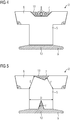
- FIG 2 shows a single tooth 2 of a sheet metal section.
- the tooth shaft 5 protrudes perpendicularly from the yoke section 6.
- the tooth head 10 is not specially shaped here and just ends without widening on the tooth shaft 5.
- the boundaries of the yoke section 6 in the radial direction and in the circumferential direction can assume a punching angle ⁇ . This punching angle is decisive for the formation of a round sheet according to FIG 1 .
- the width D of the tooth shaft 5 can be increased by AM, for example, to D 'on one side or on both sides. This can take place, for example, as a function of the current, the voltage and / or the magnetic flux of the designed electrical machine.
- an extension section 13 is formed or pressed onto the side of the tooth shaft 5, for example. In the specific example of FIG 2 Such extension sections 13 are even attached to both sides of the tooth shaft 5.
- the yoke section 6 has a recess 7 in the base element.
- This recess 7 is located in an area of reduced flow.
- the recess 7 can be filled with a flow-guiding material in view of the saturation by AM. It can be partially or completely filled with such a filling, which also represents an expansion section 13.
- cooling channels 8 in different numbers and shapes can be formed in the expansion section 13 by AM. This applies not only to the filling of the recess 7, but also to the expansion sections 13 on the tooth shaft 5.
- the areas of the sheet metal which are created by AM can be designed in layers in order to reduce losses due to eddy currents.
- the predeterminable stratification can correspond to the stratification of the electrical steel sheets or be different from this (for example fewer layers in that thicker layers are implemented).
- layer thicknesses are also possible through the AM process, so that the eddy current losses can be further reduced.
- AM processes can easily achieve layer thicknesses in the ⁇ m range.
- FIG 3 shows how FIG 2 only a single tooth 2 of a stator lamination or a stator lamination stack.
- the tooth 2 has a tooth shaft 5, a yoke portion 6 and a tooth tip 10.
- a part of the tooth tip 10 of the tooth 2 is initially straight in its punched shape, so that the tooth shaft 5 and its distal end, namely the part of the tooth tip 10, are rectangular.
- the part of the tooth tip 10 is now expanded by AM.
- tooth tip extensions 9 arise as further parts of the tooth tip on both opposite sides of the central part of the tooth tip 10, which likewise represent extension sections.
- tooth tip extensions 9 protrude essentially perpendicularly from the tooth shaft 5.
- a winding can thus be held in a form-fitting manner between yoke 6 and tooth tip extension 9.
- magnetically conductive particles can be provided in the tooth tip extensions 9 in order to additionally optimize the air gap field in the slot slot area.
- the shape and size of the tooth shaft can be designed depending on the type of motor (power, speed, harmonics, detent, efficiency, weight, continuous load, peak load, etc.).
- the AM can change the cross-section of the stator over the longitudinal extent of the motor. This means that the slot slots can also be adjusted in their axial course and in their thickness.
- the tooth has 2 of FIG 3 in its yoke 6 opposite the tooth shaft 5 a circular segment-shaped recess 7. This is in turn completely or partially filled by AM or another generative manufacturing process.
- the exit 7 was completely filled with an extension section 13.
- only a single cooling channel 8 runs through it.
- FIG 4 shows a further embodiment of a tooth 2 of a stator lamination or stator lamination stack. While the tooth tip 10 in the example of FIG 3 ends with the sheet metal cut at the distal end, in the example of FIG 4 the tooth tip 10 also in the radial direction (compare round sheet metal section 1 from FIG 1 ) expanded.
- the tooth tip extension 9 correspondingly formed by AM which represents a part of the tooth tip, accordingly not only protrudes essentially perpendicularly from the tooth shaft 5, but also extends it in the tooth tip area. This allows the distance between the stator and rotor to be varied.
- the yoke section has a recess 7 opposite the tooth shaft 5.
- the recess 7 is trapezoidal here.
- it is completely filled by AM with the formation of an extension section 13.
- Three cooling channels of different cross-sections are provided in it here. For example, there are two round cooling channels 8 and one oval cooling channel 8 in the extension section 13.
- the shape of the cooling channels 8 can, however, be varied as desired.
- FIG 5 shows a further embodiment of a tooth 2 of a stator lamination or a stator lamination stack for an electrical machine.
- a recess 11 is also provided in the tooth head 10 or tooth shaft 5, which can be at least partially filled by AM. Both recesses 7 and 11 are selected here to be wedge-shaped or triangular.
- the tooth tip extension 9, which represents an extension section formed by means of the generative manufacturing process as well as the extension section 13 on the yoke section 6, extends in the present case both in the circumferential direction and in the radial direction beyond the tooth shaft 5 and even into the tooth shaft 5 because of the recess 11 inside.
- the geometry and number of recesses 7, 11 in tooth 2 can be varied as desired.
- the number of cooling channels 8 in the recesses 7, 11 or in the extension sections 13 and 9 can be adapted to the respective circumstances.
- the recesses 7, 11 also do not have to be provided or not filled. This allows both electrical / magnetic properties and mechanical properties to be adapted and changed.
- the thickness D of the tooth shaft 5 or the width E between the recess 7 and the yoke section tooth shaft edge for the magnetic flux can be decisive dimensions. These can be varied by means of appropriate extension sections.
- the recesses 7, 11 can be designed symmetrically and / or asymmetrically.
- An asymmetrical recess can be advantageous, for example, in a preferred direction of rotation.
- a recess can be at least partially filled with the same or different materials.
- AM can fill different recesses with different materials.
- the materials can, for example, in terms of weight, permeability and / or differentiate between electrical and thermal conductivity.
- AM sensors e.g. Hall sensors, temperature sensors, humidity sensors and so on
- stator can also be attached to the stator (not shown in the figures).
- AM sensors e.g. Hall sensors, temperature sensors, humidity sensors and so on
- stator can also be embedded in the stator (also not shown in the figures).
- FIGS. 6 to 8 a special process is now presented with which a correspondingly specific stator lamination packet can be obtained.
- FIG 6 a linear array of teeth 2.
- the notches 14 can here in particular run perpendicular (punching angle 90 °) to the edge of the respective yoke section 6 of the adjacent teeth 2.
- Each notch 14 does not completely cut through the overall yoke formed from the yoke sections 6 of each tooth 2.
- the notch 14 represents an elongated cut-out which does not lead completely to the edge of the respective yoke sections 6. This results in a web 12 between the tip of the notch 14 and the edge of the adjacent yoke sections 6, which web can serve as a hinge.
- This makes it possible to punch stator laminations for the basic element in a linear shape and then to bring them into a circular shape, as shown in FIG FIG 8 is shown.
- a number of teeth 2 with a corresponding length can be produced and cut off.
- the number of tooth elements gives the respective diameter of the laminated stator core.
- the punched sheet metal elements can first be stacked and then bent or vice versa.
- FIG 8 it is shown that the bending of the individual teeth 2 around the respective webs 12 results in wedge-shaped recesses 15.
- the recesses 15 are filled by corresponding expansion sections 16.
- the extension sections 16 should have a sufficiently high permeability in order to be able to fulfill the yoke functionality. If necessary, corresponding cooling devices such as cooling channels by AM can also be integrated into the wedge-shaped recesses 15.
Abstract
Bei einer hohen Anzahl an Motortypen soll die Varianz der zu stanzenden Blechschnitte reduziert werden. Daher wird ein Statorblechpaket für eine elektrische Maschine mit einem Grundelement, welches eine Aneinanderreihung von Grund-Dynamoblechen und mehrere Zähne (2) zum Tragen jeweils einer Wicklung aufweist, vorgeschlagen. Das Statorblechpaket weist mindestens einen Erweiterungsabschnitt (13) auf, der an einem der Zähne (2) des Grundelements durch ein generatives Fertigungsverfahren angeformt ist.

Description
Die vorliegende Erfindung betrifft ein Blechpaket für eine elektrische Maschine mit einem Grundelement, welches eine Aneinanderreihung von Grund-Dynamoblechen und mehrere an seinem Umfang verteilte Zähne zum Tragen jeweils einer Wicklung aufweist. Darüber hinaus betrifft die vorliegende Erfindung eine elektrische Maschine sowie eine Maschinenfamilie mit einem derartigen Blechpaket. Ferner bezieht sich die vorliegende Erfindung auch auf ein Verfahren zum Herstellen eines Blechpakets für eine elektrische Maschine durch Ausstanzen oder Ausschneiden von Grund-Dynamoblechen und Bilden eines Grundelements durch Aneinanderreihung der gestanzten oder ausgeschnittenen Grund-Dynamobleche, wobei das Grundelement mehrere an seinem Umfang verteilte Zähne zum Tragen jeweils einer Wicklung aufweist.The present invention relates to a laminated core for an electrical machine with a base element which has a series of base dynamo sheets and a plurality of teeth distributed around its circumference, each for supporting a winding. The present invention also relates to an electrical machine and a machine family with such a laminated core. The present invention also relates to a method for producing a laminated core for an electrical machine by punching or cutting out basic dynamo sheets and forming a basic element by lining up the punched or cut-out basic dynamo sheets, the basic element having several teeth distributed around its circumference for Each has a winding.
Elektrische Maschinen wie etwa Motoren und Generatoren, besitzen in der Regel einen Stator mit einem Blechpaket. Das Blechpaket verfügt meist über zahlreiche Zähne für einzelne Wicklungen sowie ein ringförmiges Joch, das sämtliche Zähne miteinander verbindet. Ein derartiges Blechpaket wird typischerweise aus einer Vielzahl von Blechen paketiert, die aus einem Elektroblech bzw. Dynamoblech mit hoher Permeabilität ausgestanzt bzw. ausgeschnitten sind.Electrical machines such as motors and generators usually have a stator with a laminated core. The laminated core usually has numerous teeth for individual windings and a ring-shaped yoke that connects all the teeth with one another. Such a laminated core is typically packaged from a multiplicity of laminations which are punched or cut out of an electrical sheet or dynamo sheet with high permeability.
Für jeden Motortyp ist in der Regel ein eigener Blechschnitt für den Stator notwendig. Entsprechend dem Blechschnitt ist jedes Statorblech ausgestanzt. Dies führt bei einer hohen Anzahl an Motortypen zu einer ebenso hohen Anzahl von zu stanzenden Blechschnittvariationen. Der Grund hierfür liegt unter anderem darin, dass für unterschiedliche Achshöhen sowie für unterschiedliche Auslegungen (Leistung, Oberwellen etc.) unterschiedliche Statorblechschnitte notwendig sind. Die Handhabung dieser Vielzahl an Statorblechschnitten kann insbesondere eine logistische Herausforderung darstellen. Eine weitere Herausforderung kann es bedeuten, wenn ein unveränderliches Kühlkonzept für eine blechschnittabhängige Kühlung vorgesehen werden soll. Auch andere Probleme könnten sich für die Vielzahl von Motortypen mit eigenem Blechschnitt ergeben. Könnte bei einer hohen Anzahl an Motortypen die Varianz der zu stanzenden Blechschnitte reduziert werden, wäre dies unter anderem bezüglich der Umrüstzeiten der Stanzwerkzeuge vorteilhaft.A separate sheet metal cut for the stator is usually necessary for each motor type. Each stator lamination is punched out according to the sheet metal cut. With a large number of motor types, this leads to an equally high number of sheet metal cutting variations to be punched. The reason for this is, among other things, that different stator lamination cuts are necessary for different shaft heights and for different designs (power, harmonics, etc.). The handling of this large number of stator laminations can be a logistical challenge in particular. Another It can be a challenge if an unchangeable cooling concept is to be provided for cooling that is dependent on sheet metal cutting. Other problems could also arise for the large number of motor types with their own sheet metal cut. If the variance of the sheet metal cuts to be punched could be reduced with a high number of motor types, this would be advantageous, among other things, with regard to the changeover times of the punching tools.
Die Aufgabe der vorliegenden Erfindung besteht somit darin, die Anzahl an Blechschnitten für die Statoren unterschiedlicher Typen von elektrischen Maschinen möglichst gering zu halten.The object of the present invention is therefore to keep the number of sheet metal cuts for the stators of different types of electrical machines as low as possible.
Erfindungsgemäß wird diese Aufgabe durch ein Blechpaket und ein Verfahren zum Herstellen eines Blechpakets gemäß den unabhängigen Ansprüchen gelöst. Vorteilhafte Weiterbildungen der Erfindung ergeben sich aus den Unteransprüchen.According to the invention, this object is achieved by a laminated core and a method for producing a laminated core according to the independent claims. Advantageous further developments of the invention emerge from the subclaims.
Erfindungsgemäß ist demnach ein Blechpaket für eine elektrische Maschine mit einem Grundelement vorgesehen, welches eine Aneinanderreihung von Grund-Dynamoblechen und mehrere an seinem Umfang verteilte Zähne zum Tragen jeweils einer Wicklung aufweist. Bei der elektrischen Maschine handelt es sich vorzugsweise um einen Elektromotor oder einen Generator. Das Blechpaket kann ein Statorblechpaket oder ein Rotorblechpaket sein. Ebenso kann es sich bei dem Blechpaket um eine Komponente eines Aktivteils eines Linearmotors handeln.According to the invention, a laminated core for an electrical machine with a base element is accordingly provided, which has a string of base dynamo sheets and a plurality of teeth distributed around its circumference, each for supporting a winding. The electric machine is preferably an electric motor or a generator. The laminated core can be a stator laminated core or a laminated rotor core. The laminated core can also be a component of an active part of a linear motor.
Das Blechpaket weist in erster Linie ein "Grundelement" auf, das das eigentliche Paket aus Dynamoblechen darstellt. In ihm sind sogenannte "Grund-Dynamobleche" aneinandergereiht bzw. paketiert. Das Grundelement weist also einen Stapel von Grund-Dynamoblechen auf, von denen jedes ein z.B. auf ähnliche Weise ausgestanztes Dynamoblech ist. Der Name "Grund-Dynamoblech" bedeutet also lediglich, dass damit das "Grundelement" gebildet ist. Das geblechte Grundelement besitzt mehrere Zähne, die zum Tragen jeweils einer Wicklung vorgesehen sind. Diese Zähne können beispielsweise am Umfang des Grundelements insbesondere gleich verteilt sein. Generell können die Zähne an einer Wirkseite des Grundelements verteilt angeordnet sein. Prinzipiell kann jeder Zahn einen Zahnschaft und einen Zahnkopf und gegebenenfalls einen speziell geformten Zahnfuß aufweisen. Das Grundelement stellt das Grundgerüst für das Blechpaket dar und besitzt wegen der Dynamobleche eine hohe Permeabilität und damit auch eine hohe magnetische Qualität.The laminated core primarily has a "basic element" that represents the actual package of dynamo sheets. In it so-called "basic dynamo sheets" are strung together or packaged. The basic element thus has a stack of basic dynamo sheets, each of which is a dynamo sheet punched out in a similar manner, for example. The name "basic dynamo sheet" only means that the "basic element" is formed with it. The sheet metal base element has several teeth, each of which is intended to carry a winding are. These teeth can, for example, be evenly distributed on the circumference of the base element. In general, the teeth can be arranged distributed on an active side of the basic element. In principle, each tooth can have a tooth shaft and a tooth head and, if necessary, a specially shaped tooth base. The basic element represents the basic structure for the laminated core and, because of the dynamo sheets, has a high permeability and thus a high magnetic quality.
Um nun die Anzahl der Blechschnitte für unterschiedliche Typen von elektrischen Maschinen gering zu halten, besteht der Grundgedanke der Erfindung darin, das Grundelement für mehrere Typen von elektrischen Maschinen verwenden zu können. Magnetisch weniger wichtige Teile des Grundelements, wie etwa Randbereiche, können je nach Durchmesser der elektrischen Maschine, Effizienz, Einbauraum etc. durch ein 3-D-Druckverfahren bzw. allgemein ein generatives Fertigungsverfahren angepasst bzw. erweitert werden. So kann ein Erweiterungsabschnitt an einem der Zähne des Grundelements durch das generative Fertigungsverfahren an dem Zahn angeformt werden. Gegebenenfalls kann der Erweiterungsabschnitt von dem Grundelement vollständig umgeben bzw. in dieses integriert sein. So können speziell der Zahnschaft und/oder ein Jochrückenabschnitt und/oder ein Zahnkopfbereich durch den Erweiterungsabschnitt ergänzt bzw. angepasst werden.In order to keep the number of sheet metal cuts for different types of electrical machines low, the basic idea of the invention consists in being able to use the basic element for several types of electrical machines. Magnetically less important parts of the basic element, such as edge areas, can be adapted or expanded depending on the diameter of the electrical machine, efficiency, installation space, etc. by means of a 3-D printing process or generally a generative manufacturing process. Thus, an extension section on one of the teeth of the basic element can be molded onto the tooth using the additive manufacturing process. If necessary, the extension section can be completely surrounded by the basic element or integrated into it. In particular, the tooth shaft and / or a yoke back section and / or a tooth head area can be supplemented or adapted by the extension section.
Der oder die Erweiterungsabschnitte können vor und/oder nach der Paketierung eingefügt werden.The extension section or sections can be inserted before and / or after the packaging.
Das generative Fertigungsverfahren kann auch als additive Fertigung bzw. als Rapid Prototyping bezeichnet werden. Auf der Basis von Datenmodellen werden dabei aus formlosen (Flüssigkeiten, Gelen, Pasten, Pulver und Ähnlichem) oder formneutralen (bandförmigen, drahtförmigen, blattförmigen etc.) Materialien mittels chemischer und/oder physikalischer Prozesse Körper gefertigt bzw. ergänzt.The generative manufacturing process can also be referred to as additive manufacturing or rapid prototyping. On the basis of data models, bodies are manufactured or supplemented from informal (liquids, gels, pastes, powders and the like) or neutral (ribbon, wire, sheet, etc.) materials using chemical and / or physical processes.
Entsprechend einer Ausgestaltung besteht der Erweiterungsabschnitt aus mehreren Einzelabschnitten bzw. weist mehrere Einzelabschnitte auf, von denen jeder einzelne an ein jeweiliges der Grund-Dynamobleche separat durch das generative Fertigungsverfahren angeformt ist. Dies bedeutet, dass an jedes Grund-Dynamoblech durch das generative Fertigungsverfahren ein Einzelabschnitt angedruckt bzw. angeformt ist und die mehreren Einzelabschnitte durch die Aneinanderreihung bzw. Paketierung den Erweiterungsabschnitt bilden. Damit können die Einzelabschnitte an jedem Blech einzeln geformt werden. Insbesondere kann so die Stärke der Einzelabschnitte variiert werden. Beispielsweise kann ein additiv angeformter Einzelabschnitt eine andere Dicke besitzen als ein Grund-Dynamoblech. Auch kann sich die Stärke eines Einzelabschnitts beispielsweise nach außen hin vermindern.According to one embodiment, the extension section consists of a plurality of individual sections or has a plurality of individual sections, each of which is separately molded onto a respective one of the basic dynamo sheets using the additive manufacturing process. This means that an individual section is printed or molded onto each basic dynamo sheet using the generative manufacturing process and the multiple individual sections form the extension section through the stringing together or packaging. This means that the individual sections can be shaped individually on each sheet. In particular, the thickness of the individual sections can be varied in this way. For example, an additively molded individual section can have a different thickness than a basic dynamo sheet. The thickness of an individual section can also decrease towards the outside, for example.
Der Erweiterungsabschnitt kann aus einem magnetisch leitfähigen Material gebildet sein oder magnetisch leitfähige Partikel aufweisen. Auf diese Weise kann das Grundelement durch einen bzw. mehrere magnetisch wirksame Erweiterungsabschnitte ergänzt werden. Gegebenenfalls handelt es sich bei dem Material um das gleiche Material, aus dem die Grund-Dynamobleche bestehen. Ebenso können die magnetisch leitfähigen Partikel aus dem gleichen Material gebildet sein wie die Grund-Dynamobleche. Prinzipiell kann das Material der Erweiterungsabschnitte aber auch unmagnetisch sein, so dass der Erweiterungsabschnitt lediglich Stützfunktion besitzt. Gegebenenfalls kann das Material des Erweiterungsabschnitts auch so gewählt sein, dass es besondere physikalische Eigenschaften wie hohe Wärmeleitfähigkeit, geringe Dichte und so weiter besitzt.The extension section can be formed from a magnetically conductive material or have magnetically conductive particles. In this way, the basic element can be supplemented by one or more magnetically effective extension sections. The material may be the same as that of the basic dynamo sheets. The magnetically conductive particles can also be formed from the same material as the basic dynamo sheets. In principle, however, the material of the widening sections can also be non-magnetic, so that the widening section only has a supporting function. If necessary, the material of the extension section can also be selected in such a way that it has special physical properties such as high thermal conductivity, low density and so on.
In einer vorteilhaften Ausgestaltung weist der eine der Zähne einen Jochabschnitt und davon abstehend einen Zahnschaft auf, wobei der mindestens eine Erweiterungsabschnitt an dem Jochabschnitt und/oder dem Zahnschaft angeformt ist. Auf diese Weise kann die Form eines Zahnschafts verändert und insbesondere verbreitert werden. Speziell kann an beiden Seiten des Zahnschafts Material aufgetragen werden, so dass dieser eine größere Breite besitzt. Alternativ oder zusätzlich kann auch der Jochabschnitt eines Zahns verändert, angepasst bzw. ergänzt werden. So kann beispielsweise der Jochabschnitt eines Zahns mit dem Jochabschnitt eines benachbarten Zahns durch das generative Fertigungsverfahren verbunden werden. Hierdurch können beispielsweise zahlreiche Jochabschnitte vieler Zähne zu einem ringförmigen Joch verbunden werden.In an advantageous embodiment, one of the teeth has a yoke section and a tooth shaft protruding therefrom, the at least one extension section being integrally formed on the yoke section and / or the tooth shaft. In this way, the shape of a tooth shaft can be changed and in particular widened. Specifically, both sides of the Tooth shank material are applied so that it has a greater width. Alternatively or additionally, the yoke section of a tooth can also be changed, adapted or supplemented. For example, the yoke section of a tooth can be connected to the yoke section of an adjacent tooth using the additive manufacturing process. In this way, for example, numerous yoke sections of many teeth can be connected to form an annular yoke.
Des Weiteren kann vorgesehen sein, dass der eine der Zähne einen Zahnkopf aufweist und der Erweiterungsabschnitt zumindest einen Teil des Zahnkopfs bildet. Dabei kann ein Teil des Zahnkopfs ohne spezielle Formgebung lediglich das distale Ende des Zahnschafts darstellen. Ein speziell geformter bzw. vollständiger Zahnkopf entsteht dann erst durch den Erweiterungsabschnitt, der als Teil des Zahnkopfes an ein einteilig mit dem Zahnschaft verbundenen anderen Zahnkopfteil angeformt wird. Hier lassen sich in Abhängigkeit von dem Typ der elektrischen Maschine unterschiedliche Zahnköpfe generativ formen.Furthermore, it can be provided that one of the teeth has a tooth head and the widening section forms at least part of the tooth head. A part of the tooth head can only represent the distal end of the tooth shaft without a special shape. A specially shaped or complete tooth head is then only created by the extension section, which is molded as part of the tooth head onto another tooth head part that is integrally connected to the tooth shaft. Depending on the type of electrical machine, different tooth tips can be generatively shaped here.
In einer besonderen Weiterbildung des Blechpakets kann vorgesehen sein, dass in dem Erweiterungsabschnitt ein Kühlkanal ausgebildet ist. Dies bedeutet, dass durch das generative Fertigungsverfahren erstmalig oder zusätzlich Kühlkanäle in das bzw. an das Grundelement angebracht werden. Beispielsweise können in dem Erweiterungsabschnitt eine oder mehrere Kühlkanäle untergebracht werden. Insbesondere kann es sich um runde Kühlkanäle handeln, deren Durchmesser nach Bedarf gewählt ist. Auch kann der Erweiterungsabschnitt etwaige Anschlusskomponenten für ein Kühlsystem aufweisen. Vorteilhafterweise ist in diesem Fall das Material des bzw. der Erweiterungsabschnitte mit hoher Wärmeleitfähigkeit gewählt. Insbesondere kann das Material auch auf das Kühlmedium abgestimmt sein.In a special development of the laminated core, it can be provided that a cooling channel is formed in the extension section. This means that through the additive manufacturing process, cooling channels are attached to the base element for the first time or in addition. For example, one or more cooling channels can be accommodated in the extension section. In particular, it can be round cooling channels, the diameter of which is selected as required. The extension section can also have any connection components for a cooling system. In this case, the material of the extension section or sections is advantageously chosen with high thermal conductivity. In particular, the material can also be matched to the cooling medium.
Gemäß einer weiteren Ausführungsform des Blechpakets ist vorgesehen, dass der Jochabschnitt und/oder der Zahnschaft jeweils eine Aussparung aufweisen, welche durch den Erweiterungsabschnitt ganz oder teilweise gefüllt ist. So kann beispielsweise das Grundelement eine Aussparung aufweisen, die bei einem Typ der elektrischen Maschine beispielsweise aus Gewichtsgründen ungefüllt bleibt. Bei einem oder mehreren anderen Typen der elektrischen Maschine wird die Aussparung durch den Erweiterungsabschnitt gegebenenfalls auch mit einem oder mehreren Kühlkanälen gefüllt. Dabei kann der Füllungsgrad wieder vom Typ der elektrischen Maschine abhängen. Die Aussparung in dem Jochabschnitt bzw. dem Zahnschaft kann beispielsweise keilförmig, kreissegmentförmig oder trapezförmig sein.According to a further embodiment of the laminated core, it is provided that the yoke section and / or the tooth shaft each have a recess which is completely or partially filled by the expansion section. For example, the base element can have a cutout which, in one type of electrical machine, remains unfilled for reasons of weight, for example. In the case of one or more other types of electrical machine, the cutout is optionally also filled with one or more cooling channels through the expansion section. The degree of filling can again depend on the type of electrical machine. The recess in the yoke section or the tooth shaft can be, for example, wedge-shaped, circular segment-shaped or trapezoidal.
Insbesondere kann die Aussparung asymmetrisch zu einer Mittelachse des jeweiligen Zahnschafts angeordnet sein. Dies bedeutet, dass sie nicht zwangsläufig symmetrisch zur Zahnmitte sein muss. Darüber hinaus kann die Aussparung auch lediglich dazu dienen, eine bessere mechanische Stabilität für den Erweiterungsabschnitt zu erhalten. So ist es beispielsweise günstig, wenn der Zahnschaft eine Aussparung aufweist, in und um die herum das Material für einen Zahnkopf gedruckt wird. Dabei kann auch vorgesehen sein, dass die eine oder die mehreren Aussparungen Hinterschneidungen aufweisen, um etwaige Formschlüsse herzustellen.In particular, the recess can be arranged asymmetrically to a central axis of the respective tooth shaft. This means that it does not necessarily have to be symmetrical to the center of the tooth. In addition, the recess can only serve to obtain better mechanical stability for the extension section. For example, it is advantageous if the tooth shaft has a recess in and around which the material for a tooth head is printed. It can also be provided that the one or more recesses have undercuts in order to produce any form-fit connections.
In einer weiteren vorteilhaften Ausgestaltung ist die Aussparung mit mehreren verschiedenen Materialien gefüllt. Generell kann der bzw. die Erweiterungsabschnitte aus mehreren verschiedenen Materialien gedruckt bzw. gefertigt werden. Eine derartige Materialkomposition des Erweiterungsabschnitts kann an die physikalischen Anforderungen des Blechpakets angepasst werden.In a further advantageous embodiment, the recess is filled with several different materials. In general, the extension section or sections can be printed or manufactured from several different materials. Such a material composition of the extension section can be adapted to the physical requirements of the laminated core.
Entsprechend einer weiteren Ausführungsform ist der Erweiterungsabschnitt als Befestigungselement ausgebildet. Das Befestigungselement kann dazu dienen, das Blechpaket beispielsweise an einer Gehäusewand zu befestigen. Hierbei lässt sich das Befestigungselement leicht an das jeweils eingesetzte Gehäuse anpassen. Falls die elektrische Maschine gehäuselos ist, kann das Befestigungselement, das durch das generative Fertigungsverfahren an das Blechpaket angebracht wurde, auch dazu dienen, eine Befestigungsmöglichkeit auf einem Fundament, einem Träger und dergleichen zu schaffen. Bei einer weiteren vorteilhaften Ausgestaltung kann mit Hilfe des Erweiterungsabschnitts ein Sensor in die Aussparung eingebettet sein. So können beispielsweise ein Magnetsensor, ein Temperatursenor und dergleichen in das Blechpaket integriert werden. Dabei kann der Erweiterungsabschnitt als reines Halteelement aber auch als Übertragungselement für Wärme oder elektromagnetische Wellen dienen.According to a further embodiment, the extension section is designed as a fastening element. The fastening element can serve to fasten the laminated core, for example, to a housing wall. Here, the fastening element can easily be attached to the housing used to adjust. If the electrical machine does not have a housing, the fastening element that was attached to the laminated core by the additive manufacturing process can also serve to create a fastening option on a foundation, a carrier and the like. In a further advantageous embodiment, a sensor can be embedded in the cutout with the aid of the extension section. For example, a magnetic sensor, a temperature sensor and the like can be integrated into the laminated core. The extension section can serve as a pure holding element but also as a transmission element for heat or electromagnetic waves.
Ferner kann vorgesehen sein, dass an den Jochabschnitt des einen der Zähne unmittelbar ein weiterer Jochabschnitt eines weiteren der Zähne angrenzt, und der Erweiterungsabschnitt einen Keil zwischen dem Jochabschnitt und dem weiteren Jochabschnitt bildet. So kann beispielsweise ein Statorblechring aus einem linearen Blechabschnitt ausgestanzt werden, wobei die einzelnen Jochabschnitte nur über einen schmalen Steg miteinander verbunden sind. Die benachbarten Jochabschnitte können dann um den jeweiligen Steg gebogen werden, so dass sich das jeweilige ringförmige Blech ergibt. Die beim Biegen sich öffnenden Dreiecke können schließlich durch das generative Fertigungsverfahren gefüllt werden. Damit ergibt sich ein mechanisch stabiles Ringblech.Furthermore, it can be provided that a further yoke section of another of the teeth directly adjoins the yoke section of one of the teeth, and the extension section forms a wedge between the yoke section and the further yoke section. For example, a sheet metal stator ring can be punched out of a linear sheet metal section, the individual yoke sections being connected to one another only via a narrow web. The adjacent yoke sections can then be bent around the respective web, so that the respective annular sheet is obtained. The triangles that open during bending can finally be filled using the generative manufacturing process. This results in a mechanically stable ring plate.
Weiterhin kann eine elektrische Maschine mit einem Blechpaket der geschilderten Art, insbesondere einem Statorblechpaket, vorgesehen sein. Bei der elektrischen Maschine kann es sich speziell um einen Elektromotor und insbesondere um eine Synchronmaschine, eine Asynchronmaschine oder eine Reluktanzmaschine handeln.Furthermore, an electrical machine with a laminated core of the type described, in particular a stator laminated core, can be provided. The electric machine can specifically be an electric motor and in particular a synchronous machine, an asynchronous machine or a reluctance machine.
Des Weiteren kann erfindungsgemäß eine Maschinenfamilie mit mindestens zwei unterschiedlichen Maschinen der genannten Art bereitgestellt werden. Die Maschinenfamilie besitzt also eine erste elektrische Maschine und eine zweite elektrische Maschine mit dem erfindungsgemäßen Blechpaket, wobei beide elektrischen Maschinen das gleiche Grundelement, aber unterschiedliche Erweiterungsabschnitte aufweisen. Dies bedeutet, dass beide elektrische Maschinen auf dem gleichen Stanzblechpaket beruhen, wobei unterschiedliche Erweiterungsabschnitte an die Blechpakete angeformt sind. So kann beispielsweise die erste elektrische Maschine einen dickeren Zahnschaft besitzen als die zweite elektrische Maschine. In einem anderen Beispiel ist bei der ersten elektrischen Maschine eine Aussparung mit Kühlkanälen gefüllt, während bei der zweiten elektrischen Maschine die Aussparung ohne Kühlkanäle gefüllt ist. Das Merkmal "unterschiedliche Erweiterungsabschnitte" bedeutet aber auch, dass bei der einen elektrischen Maschine ein Erweiterungsabschnitt vorhanden ist, aber bei der anderen elektrischen Maschine nicht. So kann beispielsweise die erste elektrische Maschine keinen speziell ausgeformten Zahnkopf besitzen, während die zweite elektrische Maschine als Erweiterungsabschnitt einen speziell ausgeformten Zahnkopf am distalen Ende des Zahnschafts aufweist. Ähnliches kann auch für die Ausgestaltung des Zahnschafts gelten. Während bei der einen elektrischen Maschine am Zahnschaft keine Erweiterung generativ angeformt ist, kann eine solche Erweiterung am Zahnschaft der anderen elektrischen Maschine vorgesehen sein.Furthermore, a machine family with at least two different machines of the type mentioned can be provided according to the invention. The machine family therefore has a first electrical machine and a second electrical machine with the laminated core according to the invention, wherein both electrical machines have the same basic element, but different extension sections. This means that both electrical machines are based on the same stamped sheet stack, with different extension sections being molded onto the sheet stack. For example, the first electrical machine can have a thicker tooth shaft than the second electrical machine. In another example, in the first electrical machine, a recess is filled with cooling channels, while in the second electrical machine the recess is filled without cooling channels. The feature “different expansion sections” also means, however, that an expansion section is present in one electrical machine, but not in the other electrical machine. For example, the first electrical machine cannot have a specially shaped tooth head, while the second electrical machine has a specially shaped tooth head as an extension section at the distal end of the tooth shaft. The same can also apply to the design of the tooth shaft. While no extension is generatively formed on the tooth shaft in one electrical machine, such an extension can be provided on the tooth shaft of the other electrical machine.
Obige Aufgabe wird erfindungsgemäß auch gelöst durch ein Verfahren zum Herstellen eines Blechpakets für eine elektrische Maschine durch
- Ausstanzen oder Ausschneiden von Grund-Dynamoblechen und
- Bilden eines Grundelements durch Aneinanderreihung der ausgestanzten oder ausgeschnittenen Grund-Dynamobleche, wobei
- das Grundelement mehrere Zähne zum Tragen jeweils einer Wicklung aufweist sowie durch Anformen eines Erweiterungsabschnitts an einen der Zähne des Grundelements durch ein generatives Fertigungsverfahren.
- Punching or cutting out basic dynamo sheets and
- Forming a basic element by lining up the punched or cut-out basic dynamo sheets, wherein
- the base element has a plurality of teeth each for supporting a winding and by molding an extension section onto one of the teeth of the base element using a generative manufacturing process.
Die vorteilhaften Ausprägungen und Variationsmöglichkeiten, die oben im Zusammenhang mit dem Blechpaket geschildert wurden, gelten sinngemäß auch für das erfindungsgemäße Verfahren. In diesem Fall stellen die entsprechenden funktionellen Merkmale des Blechpakets die jeweiligen Verfahrensmerkmale dar.The advantageous characteristics and possible variations that have been described above in connection with the laminated core, apply mutatis mutandis to the method according to the invention. In this case, the corresponding functional features of the laminated core represent the respective process features.
Die vorliegende Erfindung wird nun anhand der beigefügten Zeichnungen näher erläutert, in denen zeigen
- FIG 1
- ein Statorblech bzw. ein Statorblechpaket in der Draufsicht;
- FIG 2
- einen Zahn eines Statorblechs mit Erweiterungsabschnitten gemäß einer ersten Ausführungsform;
- FIG 3
- einen Zahn eines Statorblechs mit Erweiterungsabschnitten gemäß einer zweiten Ausführungsform;
- FIG 4
- einen Zahn eines Statorblechs mit Erweiterungsabschnitten gemäß einer dritten Ausführungsform;
- FIG 5
- ein Statorblech mit Erweiterungsabschnitten gemäß einer vierten Ausführungsform;
- FIG 6
- einen linearen, gestanzten Blechstreifen mit mehreren Zähnen;
- FIG 7
- einen Ausschnitt von
FIG 6 zwischen zwei Zähnen und - FIG 8
- einen Teil eines Statorrings aus dem linearen Blech von
FIG 6 und eingefügten Erweiterungsabschnitten.
- FIG 1
- a stator lamination or a stator lamination packet in plan view;
- FIG 2
- a tooth of a stator lamination with extension portions according to a first embodiment;
- FIG 3
- a tooth of a stator lamination with extension portions according to a second embodiment;
- FIG 4
- a tooth of a stator lamination with extension portions according to a third embodiment;
- FIG 5
- a stator lamination with extension sections according to a fourth embodiment;
- FIG 6
- a linear, stamped sheet metal strip with several teeth;
- FIG 7
- a section of
FIG 6 between two teeth and - FIG 8
- part of a stator ring from the linear sheet of
FIG 6 and inserted extension sections.
Die nachfolgend näher geschilderten Ausführungsbeispiele stellen bevorzugte Ausführungsformen der vorliegenden Erfindung dar. Dabei ist zu beachten, dass die einzelnen Merkmale nicht nur in den geschilderten Merkmalskombinationen, sondern auch in Alleinstellung oder in anderen technisch sinnvollen Kombinationen realisiert werden können.The exemplary embodiments described in more detail below represent preferred embodiments of the present invention. It should be noted that the individual features can be implemented not only in the described feature combinations, but also on their own or in other technically meaningful combinations.
Zur Herstellung eines Blechpakets und insbesondere eines Statorblechpakets für eine elektrische Maschine (z.B. Asynchronmaschine, Synchronmaschine, Reluktanzmaschine etc.) werden nicht nur (gestanzte) Bleche in Umfangsrichtung und/oder axial zu einem Grundelement aneinandergereiht. Zusätzlich werden Teile des Blechpakets beispielsweise durch ein 3-D-Druckverfahren gedruckt. Es werden also an das Grundelement durch ein generatives Fertigungsverfahren ein oder mehrere Erweiterungsabschnitte angeformt.To produce a laminated core and in particular a laminated stator core for an electrical machine (e.g. asynchronous machine, synchronous machine, reluctance machine, etc.), not only (punched) sheets are lined up in the circumferential direction and / or axially to form a basic element. In addition, parts of the laminated core are printed using a 3-D printing process, for example. So there will be the basic element one or more extension sections are formed using a generative manufacturing process.
Auf diese Weise kann eine hohe Varianz von zum Beispiel Motortypen bereitgestellt werden, ohne von Seiten des Herstellers die Varianz der gestanzten Blechschnitte zu erhöhen. Somit ergibt sich der Vorteil einheitlicher Blechschnitte für unterschiedliche Achsgrößen bzw. für ein gewisses Spektrum von Achshöhen (zum Beispiel Achshöhen 15 bis 350 Millimeter; 360 bis 1000 Millimeter; größer 1000 Millimeter). Außerdem ergibt sich der Vorteil von einheitlichen Blechschnitten für unterschiedliche Auslegungen, beispielsweise bezüglich Leistung, Oberwellen etc. Ein weiterer Vorteil kann darin bestehen, dass mit dem generativen Fertigungsverfahren ein adaptives Kühlkonzept realisiert werden kann.In this way, a high variance of, for example, engine types can be provided without the manufacturer increasing the variance of the punched sheet metal cuts. This results in the advantage of uniform sheet metal cuts for different axle sizes or for a certain range of axle heights (for example axle heights from 15 to 350 millimeters; 360 to 1000 millimeters; greater than 1000 millimeters). In addition, there is the advantage of uniform sheet metal cuts for different designs, for example with regard to power, harmonics, etc. Another advantage can be that an adaptive cooling concept can be implemented with the additive manufacturing process.
In einer Ausgestaltung der Erfindung weist also ein Statorblechpaket bzw. ein Stator ein Grundelement auf. Das Grundelement seinerseits weist eine insbesondere axiale Aneinanderreihung von Blechen bzw. Dynamo-blechen auf. Vorteilhaft weisen die Bleche eine hohe Permeabilität auf und sind somit von hoher Qualität. Dieses Grundelement wird durch ein generatives Fertigungsverfahren bzw. AM (Additiv Manufacturing) wie beispielsweise 3-D-Druck ergänzt. So können durch AM beispielsweise Randbereiche des jeweiligen Blechs und/oder des Statorblechpakets individuell gestaltet werden.In one embodiment of the invention, a laminated stator core or a stator has a base element. The basic element, for its part, has a particularly axial series of sheets or dynamo sheets. The sheets advantageously have a high permeability and are therefore of high quality. This basic element is supplemented by a generative manufacturing process or AM (Additive Manufacturing) such as 3-D printing. For example, edge areas of the respective sheet metal and / or the stator core can be individually designed by AM.
Für den AM-Prozess wird das Grundelement beispielsweise in einer Hilfskonstruktion fixiert. Denkbar ist stattdessen oder ergänzend eine Stanzpaketierung des Grundelements, so dass das Grundelement von vornherein eine Grundstabilität aufweist, die die Handhabung bzw. den weiteren Herstellungsprozess vereinfacht. Durch AM (nachfolgend stellvertretend für generative Fertigungsverfahren) kann beispielsweise der Durchmesser des Stators verändert werden. Abhängig vom erwarteten maximalen Fluss kann auch das Joch des Stators vergrößert werden, um zu vermeiden, dass das Joch in Sättigung gehen kann. Dies bedeutet, dass AM auch zur Leistungsanpassung der elektrischen Maschine herangezogen werden kann (Effizienzbetrachtung). Neben dem Joch kann aber auch ein Zahnschaft, ein Zahnkopf und/oder ein Kühlmittel durch AM angepasst werden. Auch eine Gewichtsoptimierung ist möglich. So kann bei gleichem Motorgehäuse der Stator einer Maschine mit geringerer maximaler Leistung leichter ausgeführt werden, aber dennoch an einen großen Einbauraum innerhalb eines großen Gehäuses angepasst sein.For the AM process, for example, the basic element is fixed in an auxiliary construction. Instead or in addition, it is conceivable that the base element may be packaged by punching, so that the base element has a basic stability from the outset that simplifies handling and the further manufacturing process. With AM (hereinafter representative of additive manufacturing processes), for example, the diameter of the stator can be changed. Depending on the expected maximum flux, the yoke of the stator can also be enlarged in order to prevent the yoke from going into saturation. This means that AM can also be used to adjust performance the electrical machine can be used (efficiency consideration). In addition to the yoke, however, a tooth shaft, a tooth head and / or a coolant can also be adapted by AM. Weight optimization is also possible. Thus, with the same motor housing, the stator of a machine with a lower maximum power can be made lighter, but still be adapted to a large installation space within a large housing.
Im Folgenden werden anhand der beigefügten Figuren einzelne konkrete Beispiele aufgezeigt. So zeigt beispielsweise
Eine elektrische Maschine einer Maschinenfamilie kann mit einem solchen Grundelement bzw. Statorblechpaket in unveränderter Form gefertigt werden. Bei einem weiteren Mitglied der Maschinenfamilie kann das Blechpaket entsprechend den nachfolgenden Beispielen durch ein generatives Fertigungsverfahren verändert bzw. mit entsprechenden Erweiterungsabschnitten ergänzt werden. Damit ergeben sich für die Maschinenfamilie basierend auf dem Grundelement unterschiedliche Typen von elektrischen Maschinen bzw. Motoren.An electrical machine of a machine family can be manufactured with such a basic element or stator core in unchanged form. In the case of another member of the machine family, the laminated core can be changed using a generative manufacturing process or supplemented with corresponding expansion sections as shown in the following examples. This results in different types of electrical machines or motors for the machine family based on the basic element.
Das in
Ein Blechschnitt 1 besitzt eine Vielzahl an Zähnen 2, die hier radial nach innen ragen. Die Zähne 2 sind durch Nuten 3 voneinander getrennt. Der Blechschnitt 1 besitzt hier insgesamt eine ringförmige Gestalt, wobei die einzelnen Zähne 2 zu einer zentralen Achse 4 weisen.A sheet metal section 1 has a large number of
Jeder Zahn besitzt einen Zahnschaft 5 und einen Jochabschnitt 6. Die einzelnen Jochabschnitte 6 aller Zähne fügen sich zu einem geschlossenen, ringförmigen Joch. Von jedem Jochabschnitt 6 eines Zahns steht der jeweilige Zahnschaft 5 des Zahns senkrecht zur Achse 4 gerichtet ab. Am distalen Ende, das heißt dem nach innen weisenden Ende, jedes Zahnschafts 5 befindet sich ein Zahnkopf 10, der besonders ausgeformt sein kann oder lediglich das Ende des Zahnschafts 5 darstellt.Each tooth has a
Die Breite D des Zahnschafts 5 kann durch AM beispielsweise auf D' einseitig oder zweiseitig erhöht werden. Dies kann beispielsweise in Abhängigkeit von dem Strom, der Spannung und/oder dem magnetischen Fluss der entworfenen elektrischen Maschine erfolgen. Durch AM wird hier also beispielsweise seitlich an den Zahnschaft 5 ein Erweiterungsabschnitt 13 angeformt bzw. angedruckt. Im konkreten Beispiel von
Darüber hinaus weist in dem vorliegenden Beispiel der Jochabschnitt 6 im Grundelement eine Aussparung 7 auf. Diese Aussparung 7 befindet sich in einem Bereich reduzierten Flusses. Abhängig vom erwarteten Maximalfluss kann die Aussparung 7 im Hinblick auf die Sättigung durch AM mit einem flussführenden Material gefüllt werden. Sie kann teilweise oder vollständig mit einer solchen Füllung gefüllt sein, die ebenfalls einen Erweiterungsabschnitt 13 darstellt.In addition, in the present example the
Abhängig von der benötigten Kühlung können durch AM Kühlkanäle 8 in unterschiedlicher Anzahl und Form in dem Erweiterungsabschnitt 13 ausgebildet werden. Dies gilt nicht nur für die Füllung der Aussparung 7, sondern auch für die Erweiterungsabschnitte 13 an dem Zahnschaft 5.Depending on the cooling required, cooling
Die Bereiche des Blechs, welche durch AM erstellt werden, das heißt die Erweiterungsabschnitte 13, können schichtartig ausgebildet sein, um Verluste durch Wirbelströme zu reduzieren. Die vorgebbare Schichtung kann der Schichtung der Elektrobleche entsprechen oder von dieser unterschiedlich sein (zum Beispiel weniger Schichten, indem dickere Schichten realisiert werden). An den Rändern der Zähne 2 sind dabei auch wesentlich geringere Schichtdicken als die Blechstärke durch den AM-Prozess möglich, so dass dadurch die Wirbelstromverluste weiter reduziert werden können. So können beispielsweise durch AM-Prozesse ohne Weiteres Schichtdicken im µm-Bereiche realisiert werden.The areas of the sheet metal which are created by AM, that is to say the
Die Form und Größe des Zahnschafts kann abhängig vom Motortyp (Leistung, Drehzahl, Oberwellen, Rastung, Effizienz, Gewicht, Dauerlast, Spitzenlast, etc.) ausgeführt werden. Durch das AM kann sich der Querschnitt des Stators über die Längsausdehnung des Motors ändern. Damit sind die Nutschlitze in ihrem axialen Verlauf und in ihrer Dicke zusätzlich einstellbar.The shape and size of the tooth shaft can be designed depending on the type of motor (power, speed, harmonics, detent, efficiency, weight, continuous load, peak load, etc.). The AM can change the cross-section of the stator over the longitudinal extent of the motor. This means that the slot slots can also be adjusted in their axial course and in their thickness.
Anstelle der dreieckigen Aussparung gemäß
Auch im vorliegenden Fall weist der Jochabschnitt eine Aussparung 7 gegenüber dem Zahnschaft 5 auf. Die Aussparung 7 ist hier trapezförmig ausgebildet. Sie ist hier ebenfalls durch AM unter Bildung eines Erweiterungsabschnitts 13 vollständig gefüllt. In ihr sind hier drei Kühlkanäle unterschiedlichen Querschnitts vorgesehen. Z.B. befinden sich in dem Erweiterungsabschnitt 13 zwei runde Kühlkanäle 8 und ein ovaler Kühlkanal 8. Die Form der Kühlkanäle 8 kann jedoch beliebig variiert werden.In the present case, too, the yoke section has a
Die Geometrie und Anzahl der Aussparungen 7, 11 in dem Zahn 2 können beliebig variiert werden. Ebenso kann die Anzahl der Kühlkanäle 8 in den Aussparungen 7, 11 bzw. in dem Erweiterungsabschnitten 13 und 9 an die jeweiligen Gegebenheiten angepasst werden. Im Einzelfall müssen die Aussparungen 7, 11 auch nicht vorgesehen bzw. nicht gefüllt sein. Dadurch lassen sich sowohl elektrische/magnetische Eigenschaften wie auch mechanische Eigenschaften anpassen und ändern. Entscheidende Maße können die Dicke D des Zahnschafts 5 oder die Weite E zwischen der Aussparung 7 und Jochabschnitt-Zahnschaft-Kante für den magnetischen Fluss sein. Diese lassen sich durch entsprechende Erweiterungsabschnitte variieren.The geometry and number of
Die Aussparungen 7, 11 können symmetrisch und/oder asymmetrisch ausgebildet sein. Eine asymmetrische Aussparung kann zum Beispiel bei einer bevorzugten Drehrichtung vorteilhaft sein.The
Durch AM kann ferner eine Aussparung mit gleichen oder unterschiedlichen Materialien zumindest teilweise gefüllt sein. Außerdem können durch AM unterschiedliche Aussparungen mit unterschiedlichen Materialien gefüllt werden. Die Materialien können sich z.B. bezüglich Gewicht, Permeabilität und/oder elektrischer wie auch thermischer Leitfähigkeit unterscheiden.Furthermore, by means of AM, a recess can be at least partially filled with the same or different materials. In addition, AM can fill different recesses with different materials. The materials can, for example, in terms of weight, permeability and / or differentiate between electrical and thermal conductivity.
Mit Hilfe der AM können auch Befestigungselemente an den Stator angebracht werden (in den Figuren nicht dargestellt). Darüber hinaus können durch AM auch Sensoren (z.B. Hallsensor, Temperatursensor, Feuchtigkeitssensor und so weiter) in den Stator eingebettet werden (in den Figuren ebenfalls nicht dargestellt).With the aid of the AM, fastening elements can also be attached to the stator (not shown in the figures). In addition, AM sensors (e.g. Hall sensors, temperature sensors, humidity sensors and so on) can also be embedded in the stator (also not shown in the figures).
Anhand der
Wie der vergrößerte Abschnitt VII in
In
Claims (15)
Priority Applications (1)
| Application Number | Priority Date | Filing Date | Title |
|---|---|---|---|
| EP19185464.5A EP3764511A1 (en) | 2019-07-10 | 2019-07-10 | Laminated stator package with pressed extension |
Applications Claiming Priority (1)
| Application Number | Priority Date | Filing Date | Title |
|---|---|---|---|
| EP19185464.5A EP3764511A1 (en) | 2019-07-10 | 2019-07-10 | Laminated stator package with pressed extension |
Publications (1)
| Publication Number | Publication Date |
|---|---|
| EP3764511A1 true EP3764511A1 (en) | 2021-01-13 |
Family
ID=67226130
Family Applications (1)
| Application Number | Title | Priority Date | Filing Date |
|---|---|---|---|
| EP19185464.5A Pending EP3764511A1 (en) | 2019-07-10 | 2019-07-10 | Laminated stator package with pressed extension |
Country Status (1)
| Country | Link |
|---|---|
| EP (1) | EP3764511A1 (en) |
Cited By (1)
| Publication number | Priority date | Publication date | Assignee | Title |
|---|---|---|---|---|
| DE102021204537A1 (en) | 2021-05-05 | 2022-11-10 | Zf Friedrichshafen Ag | Sensor blade for integrating a sensor in an electrical machine, stator for an electrical machine and method for operating a sensor blade |
Citations (5)
| Publication number | Priority date | Publication date | Assignee | Title |
|---|---|---|---|---|
| JP2007325353A (en) * | 2006-05-30 | 2007-12-13 | Mitsubishi Electric Corp | Stator of electromagnetic machine |
| DE102011109129A1 (en) * | 2011-07-14 | 2013-01-17 | Fraunhofer-Gesellschaft zur Förderung der angewandten Forschung e.V. | Electric energy converter and method for its production |
| WO2013045142A2 (en) * | 2011-09-30 | 2013-04-04 | Robert Bosch Gmbh | Method for producing a machine component for an electrical machine, machine component and electrical machine |
| JP2015171193A (en) * | 2014-03-05 | 2015-09-28 | アスモ株式会社 | Armature core and armature |
| EP3076526A1 (en) * | 2015-04-02 | 2016-10-05 | Hamilton Sundstrand Corporation | Stator heat transfer feature |
-
2019
- 2019-07-10 EP EP19185464.5A patent/EP3764511A1/en active Pending
Patent Citations (5)
| Publication number | Priority date | Publication date | Assignee | Title |
|---|---|---|---|---|
| JP2007325353A (en) * | 2006-05-30 | 2007-12-13 | Mitsubishi Electric Corp | Stator of electromagnetic machine |
| DE102011109129A1 (en) * | 2011-07-14 | 2013-01-17 | Fraunhofer-Gesellschaft zur Förderung der angewandten Forschung e.V. | Electric energy converter and method for its production |
| WO2013045142A2 (en) * | 2011-09-30 | 2013-04-04 | Robert Bosch Gmbh | Method for producing a machine component for an electrical machine, machine component and electrical machine |
| JP2015171193A (en) * | 2014-03-05 | 2015-09-28 | アスモ株式会社 | Armature core and armature |
| EP3076526A1 (en) * | 2015-04-02 | 2016-10-05 | Hamilton Sundstrand Corporation | Stator heat transfer feature |
Cited By (1)
| Publication number | Priority date | Publication date | Assignee | Title |
|---|---|---|---|---|
| DE102021204537A1 (en) | 2021-05-05 | 2022-11-10 | Zf Friedrichshafen Ag | Sensor blade for integrating a sensor in an electrical machine, stator for an electrical machine and method for operating a sensor blade |
Similar Documents
| Publication | Publication Date | Title |
|---|---|---|
| EP2688183B1 (en) | Cast electric coil | |
| EP1114500B1 (en) | Electric motor | |
| EP2951909B1 (en) | Rotor, reluctance machine and production method for a rotor | |
| DE19829052C1 (en) | Synchronous linear motor for linear motor setting | |
| DE19728172A1 (en) | Electrical machine with soft magnetic teeth and process for their manufacture | |
| DE102011008198A1 (en) | Stator for an electric machine | |
| EP3545610B1 (en) | Synchronous machine having magnetic rotary field reduction and flux concentration | |
| WO2012038377A2 (en) | Machine component for an electrical machine | |
| EP1955426A1 (en) | Arrangement of rotor laminates of a permanently excited electrical machine | |
| WO2016020120A2 (en) | Sheet metal part or sintered part for a stator or a rotor of an electrical machine and method for producing same | |
| DE102017201178A1 (en) | Mechanical component and method for producing a machine component | |
| WO2002019504A1 (en) | Electric machine for high magnetic reversal frequencies | |
| AT522711A1 (en) | Stator for an axial flux machine | |
| EP2601726A2 (en) | Winding tooth and component for an electrical machine for reducing eddy currents | |
| EP3381107B1 (en) | Electrical sheet having printed web | |
| EP3764511A1 (en) | Laminated stator package with pressed extension | |
| WO2014049007A1 (en) | Active part of an electrical machine, radial magnetic bearing and method for producing a radial magnetic bearing | |
| EP3813237B1 (en) | Coil module for an electric machine | |
| DE19953291A1 (en) | Coil tooth for accommodating coil for magnetic circuit of electro-magneto-mechanical converter, has individual disc-shaped elements in series or stacked and connected to form coil tooth | |
| EP3706287A1 (en) | Sheet metal stack of a stator | |
| EP1376815A1 (en) | Electrical machine | |
| DE102015202004A1 (en) | Squirrel-cage rotor with stable short-circuit ring for an electrical asynchronous machine and method of making the same | |
| DE202013000369U1 (en) | Rotary actuator with high torque and low inductance | |
| DE102013226149A1 (en) | Machine component for an electric machine and method for manufacturing a machine component | |
| WO2008034792A1 (en) | Synchronous machine |
Legal Events
| Date | Code | Title | Description |
|---|---|---|---|
| PUAI | Public reference made under article 153(3) epc to a published international application that has entered the european phase |
Free format text: ORIGINAL CODE: 0009012 |
|
| STAA | Information on the status of an ep patent application or granted ep patent |
Free format text: STATUS: THE APPLICATION HAS BEEN PUBLISHED |
|
| AK | Designated contracting states |
Kind code of ref document: A1 Designated state(s): AL AT BE BG CH CY CZ DE DK EE ES FI FR GB GR HR HU IE IS IT LI LT LU LV MC MK MT NL NO PL PT RO RS SE SI SK SM TR |
|
| AX | Request for extension of the european patent |
Extension state: BA ME |
|
| STAA | Information on the status of an ep patent application or granted ep patent |
Free format text: STATUS: REQUEST FOR EXAMINATION WAS MADE |
|
| 17P | Request for examination filed |
Effective date: 20210712 |
|
| RBV | Designated contracting states (corrected) |
Designated state(s): AL AT BE BG CH CY CZ DE DK EE ES FI FR GB GR HR HU IE IS IT LI LT LU LV MC MK MT NL NO PL PT RO RS SE SI SK SM TR |
|
| RAP1 | Party data changed (applicant data changed or rights of an application transferred) |
Owner name: INNOMOTICS GMBH |