EP3764006A1 - Device for generating an air blade barrier - Google Patents
Device for generating an air blade barrier Download PDFInfo
- Publication number
- EP3764006A1 EP3764006A1 EP20000239.2A EP20000239A EP3764006A1 EP 3764006 A1 EP3764006 A1 EP 3764006A1 EP 20000239 A EP20000239 A EP 20000239A EP 3764006 A1 EP3764006 A1 EP 3764006A1
- Authority
- EP
- European Patent Office
- Prior art keywords
- air flow
- upright
- air
- passage
- series
- Prior art date
- Legal status (The legal status is an assumption and is not a legal conclusion. Google has not performed a legal analysis and makes no representation as to the accuracy of the status listed.)
- Granted
Links
Images





Classifications
-
- F—MECHANICAL ENGINEERING; LIGHTING; HEATING; WEAPONS; BLASTING
- F24—HEATING; RANGES; VENTILATING
- F24F—AIR-CONDITIONING; AIR-HUMIDIFICATION; VENTILATION; USE OF AIR CURRENTS FOR SCREENING
- F24F9/00—Use of air currents for screening, e.g. air curtains
-
- E—FIXED CONSTRUCTIONS
- E06—DOORS, WINDOWS, SHUTTERS, OR ROLLER BLINDS IN GENERAL; LADDERS
- E06B—FIXED OR MOVABLE CLOSURES FOR OPENINGS IN BUILDINGS, VEHICLES, FENCES OR LIKE ENCLOSURES IN GENERAL, e.g. DOORS, WINDOWS, BLINDS, GATES
- E06B9/00—Screening or protective devices for wall or similar openings, with or without operating or securing mechanisms; Closures of similar construction
- E06B9/56—Operating, guiding or securing devices or arrangements for roll-type closures; Spring drums; Tape drums; Counterweighting arrangements therefor
- E06B9/58—Guiding devices
- E06B9/582—Means to increase gliss, light, sound or thermal insulation
-
- F—MECHANICAL ENGINEERING; LIGHTING; HEATING; WEAPONS; BLASTING
- F24—HEATING; RANGES; VENTILATING
- F24F—AIR-CONDITIONING; AIR-HUMIDIFICATION; VENTILATION; USE OF AIR CURRENTS FOR SCREENING
- F24F13/00—Details common to, or for air-conditioning, air-humidification, ventilation or use of air currents for screening
- F24F13/02—Ducting arrangements
- F24F13/06—Outlets for directing or distributing air into rooms or spaces, e.g. ceiling air diffuser
-
- F—MECHANICAL ENGINEERING; LIGHTING; HEATING; WEAPONS; BLASTING
- F24—HEATING; RANGES; VENTILATING
- F24F—AIR-CONDITIONING; AIR-HUMIDIFICATION; VENTILATION; USE OF AIR CURRENTS FOR SCREENING
- F24F13/00—Details common to, or for air-conditioning, air-humidification, ventilation or use of air currents for screening
- F24F13/02—Ducting arrangements
- F24F13/06—Outlets for directing or distributing air into rooms or spaces, e.g. ceiling air diffuser
- F24F13/072—Outlets for directing or distributing air into rooms or spaces, e.g. ceiling air diffuser of elongated shape, e.g. between ceiling panels
-
- E—FIXED CONSTRUCTIONS
- E06—DOORS, WINDOWS, SHUTTERS, OR ROLLER BLINDS IN GENERAL; LADDERS
- E06B—FIXED OR MOVABLE CLOSURES FOR OPENINGS IN BUILDINGS, VEHICLES, FENCES OR LIKE ENCLOSURES IN GENERAL, e.g. DOORS, WINDOWS, BLINDS, GATES
- E06B9/00—Screening or protective devices for wall or similar openings, with or without operating or securing mechanisms; Closures of similar construction
- E06B9/56—Operating, guiding or securing devices or arrangements for roll-type closures; Spring drums; Tape drums; Counterweighting arrangements therefor
- E06B9/58—Guiding devices
- E06B2009/586—Guiding devices with heating to prevent frost or condensate
-
- F—MECHANICAL ENGINEERING; LIGHTING; HEATING; WEAPONS; BLASTING
- F24—HEATING; RANGES; VENTILATING
- F24F—AIR-CONDITIONING; AIR-HUMIDIFICATION; VENTILATION; USE OF AIR CURRENTS FOR SCREENING
- F24F9/00—Use of air currents for screening, e.g. air curtains
- F24F2009/002—Room dividers
-
- F—MECHANICAL ENGINEERING; LIGHTING; HEATING; WEAPONS; BLASTING
- F24—HEATING; RANGES; VENTILATING
- F24F—AIR-CONDITIONING; AIR-HUMIDIFICATION; VENTILATION; USE OF AIR CURRENTS FOR SCREENING
- F24F9/00—Use of air currents for screening, e.g. air curtains
- F24F2009/005—Use of air currents for screening, e.g. air curtains combined with a door
-
- F—MECHANICAL ENGINEERING; LIGHTING; HEATING; WEAPONS; BLASTING
- F24—HEATING; RANGES; VENTILATING
- F24F—AIR-CONDITIONING; AIR-HUMIDIFICATION; VENTILATION; USE OF AIR CURRENTS FOR SCREENING
- F24F9/00—Use of air currents for screening, e.g. air curtains
- F24F2009/007—Use of air currents for screening, e.g. air curtains using more than one jet or band in the air curtain
-
- F—MECHANICAL ENGINEERING; LIGHTING; HEATING; WEAPONS; BLASTING
- F24—HEATING; RANGES; VENTILATING
- F24F—AIR-CONDITIONING; AIR-HUMIDIFICATION; VENTILATION; USE OF AIR CURRENTS FOR SCREENING
- F24F13/00—Details common to, or for air-conditioning, air-humidification, ventilation or use of air currents for screening
- F24F13/02—Ducting arrangements
- F24F13/06—Outlets for directing or distributing air into rooms or spaces, e.g. ceiling air diffuser
- F24F2013/0608—Perforated ducts
Definitions
- the present invention refers in general to portal structures for industrial use, adapted to separate two adjacent environments at different temperatures.
- the invention concerns a device for generating an air blade barrier between two environments in communication with each other through a portal structure that defines a passage.
- the reduction or elimination of the heat exchanges between two adjacent environments at different temperatures can be obtained by using a barrier of the so-called "air blade” type, essentially consisting of a continuous air flow that passes in parallel through the surface of a communication passage defined by a portal structure, between the two environments to be kept separated.
- the air flow of the barrier which usually moves along a single direction, allows to prevent the air to pass from one environment to the other, so as to limit the heat exchange between the two environments and to facilitate the thermal insulation thereof.
- the invention concerns a device for generating an air blade barrier of the type defined in the preamble of appended claim 1.
- a device for generating an air blade barrier of the type defined above is disclosed by GB-2397116-A1 .
- This document describes an industrial door having a pair of closure members that can be folded like an accordion in a position adjacent to a respective side upright of the portal structure in the open condition, which are supported in a laterally slidable manner.
- a fan arranged inside the upper cross member of the portal structure generates an air flow, for example having a horizontal direction, coplanar with a passage defined by the portal structure, which air flow is ejected from air discharge openings formed in a first upright and is sucked through openings formed in the second upright opposite to the first one, so as to generate a continuous circulation of air which pass through the passage to create an air blade barrier.
- the device for generating an air blade barrier of this document is not particularly efficient in the operation.
- the main object of the present invention is to propose a device for generating an air blade barrier, having an improved efficacy, the structure of which is simple so as to require rather low production costs and comprising modular elements to allow it to be adapted to different configurations of use.
- the device comprises fan means incorporated in each of said uprights, that each upright comprises both said air flow inlet opening and said air flow outlet opening, and that the device allows a pair of independent air flows to be generated at opposite areas of the passage of the portal structure, which create together a double air blade barrier, it is possible to obtain a device for generating an air blade barrier having very high seal characteristics for the heat exchange between the two environments upstream and downstream of the portal structure.
- a series of fans is mounted in each upright, which series comprises fans arranged at different heights with respect to the portal structure, the fans of each upright being arranged symmetrically with respect to the fans of the other upright.
- the speed of the air flow delivered by a pair of fans arranged at a same height in the two uprights is selectively controlled so that the respective air blade barrier portions generated by them are adapted to compensate for the heat exchange at that height.
- the device comprises at least one slidable closure member for closing said passage, each upright comprising at least one vertical guide rail for guiding the sliding of a side edge of said at least one closure member, said two air blade barriers generating a pair of air flows having opposite directions, both of which are arranged adjacent to said at least one closure member.
- the association of the device for generating an air blade barrier with a closure member of the portal structure allows the characteristics of seal of heat exchanges between the two adjacent environments to be improved. Moreover, in this case, the speed of rotation of the fans of the pairs of fans arranged at a same height can be adjusted also taking into account the open portion of the passage as a function of the position of the closure member at that moment.
- the two air blade barriers are both arranged on a same side of said at least one closure member. This makes it possible to generate a vortical flow by means of the two adjacent air blade barriers, which effectively traps possible foreign matters in the air flow, preventing these possible foreign matters to enter one of the two adjacent environments.
- the double air blade barrier consists of a first air blade barrier arranged on the side of a first side of said closure member, and of a second air blade barrier arranged on the side of a second side of said closure member. Also this type of double air blade barrier, which includes an air blade barrier on each side of the closure member, allows a sort of vortical movement of the air to be generated around the closure member, which allows a very effective seal to be obtained against the heat exchange between two adjacent environments at different temperatures.
- a device for generating an air blade barrier comprises a portal structure indicated 10 as a whole.
- the structure 10 defines a passage 12 between a pair of opposite vertical uprights 14 and 16, as well as between a horizontal upper cross member 18 which is connected to the upper ends of the uprights 14 and 16, and a base plane 20.
- Each upright 14, 16 has an inner cavity 26 in which a series of respective fans 28 are mounted, which are placed at different heights, the fans 28 being arranged symmetrically in the two uprights 14, 16.
- each upright 14, 16 communicates with the passage 12 through an input opening preferably formed by aligned series of holes 30, and an outlet opening in the form of a longitudinal slit 32.
- each upright 14, 16 comprises a series of openings, or holes, 30 for entry of the air flow, and a respective slit 32 for the exit of the air flow, the series of holes 30 and the slit 32 extending substantially parallel to the corresponding upright 14, 16.
- the series of holes 30 and the slit 32 of the upright 14 face directly the slit 32 and the series of holes 30 of the upright 16, respectively.
- another embodiment of the invention comprises the same portal structure 10 already described for the previous embodiment, to which a movable closure member 22 is associated, for example consisting of at least one flexible and vertically slidable curtain, for closing the passage 12.
- the flexible curtain 22 is made by means of a continuous sheet of plastic or plasticized textile material, having a transverse upper edge secured, in a per se known manner, to a rotatable winding shaft (not shown) housed inside the cross member 18.
- the rotation of the winding shaft about its own axis is controlled by a motorized control unit that can be operated by a user, for example by means of one or more control buttons 23, by means of which the quick rising and descent of the curtain 22 into the passage 12 can be controlled, which forms in this manner a closure of the "quick sliding" type, that is in which opening and closing are performed with a relatively high speed, or by an automatic control including sensors of a known type adapted to detect the passage of a body in the vicinity of the passage 12.
- the movable closure member 22 could be different from the curtain considered above, and be movable with respect to the opening 12 in a not quick manner, according to a conventional operation.
- the device comprises a pair of guide rails 24, each of which is rigidly connected to a respective vertical upright 14, 16, in which the opposite side edges of the curtain 22 are slidably engaged.
- the guide rail 24 of the upright 14 is arranged in a position more adjacent to the upstream environment with respect to the portal structure 10.
- An elongated slit 32 extending longitudinally along the respective upright in order to allow the air flow to exit, is formed at a position parallel to and spaced from said rail 24, a series of inlet openings, or holes, 30 being interposed between the rail 24 and the slit 32.
- the opposite upright 16 also includes a guide rail 24 facing the guide rail 24 of the upright 14, which extends longitudinally with respect to the relevant upright and a series of inlet openings, or holes, 30, in a position parallel to and spaced therefrom, a respective elongated slit 32 being interposed between the rail 24 and the series of holes 30.
- At least one of the air blade barriers laps at least partially onto the closure member 22, or a zone adjacent to it, thus preventing a direct contact between this closure member and the air of the environment downstream of the portal structure, thus limiting the heat exchange between the two environments even when the closure member moves along the portal structure to allow the passage of persons and/or objects.
- each of the uprights 14, 16 comprises a respective guide rail 24 for the sliding engagement of the opposite edges of the curtain 22.
- an inlet opening consisting of the series of holes 30 is formed in each upright 14, 16 on one side of the rail 24, as well as a respective longitudinal slit 32 that constitutes the air flow outlet opening, at the opposite side of the guide rail 24. Since the uprights 14, 16 in the mounted condition have respective rails 24 placed at a central position, and the series of holes 30 and the respective longitudinal slit 32 at respectively opposite positions, the two uprights have a symmetrical shape.
- the series of holes 30, or air flow inlet openings extends in a zone close to the guide rail 24 of each upright 14, 16, at an upstream side with respect to the guide rail 24, while the air flow output slit 32 extends in each upright 14, 16 on the downstream side with respect to the guide rail 24, so that the series of air flow inlet openings 30 and the air flow outlet slit 32 are arranged on each upright at opposite positions with respect to the relative guide rail 24, and facing the series of apertures 30 and the slit 32 of the opposite upright.
- the two air blade barriers thus formed pass through the passage 12 with generally opposite flow directions with respect to the plane of the passage 12, and at a position substantially adjacent to the opposite sides of the curtain 22, which allows an optimum seal to be obtained towards the heat exchanges between the environments upstream and downstream of the curtain 22, even when the curtain 22 is raised to allow the passage through the passage 12.
- the air blade barriers each constituted by the two half-barriers 38 and 40 generate a continuous vortical circulation at the central part of the passage 12, which allows to improve the seal against the heat exchanges between the two environments upstream and downstream of the curtain 22, and to confine and/or effectively expel possible impurities or foreign agents present in the air flow.
- the speed of the pairs of fans 28 placed at the same height in the two uprights 14 and 16 can be selectively adjusted in order to change the intensity of the air flow at the passage 12 as a function of the height, for the same purposes mentioned above in connection with the previous embodiments.
- each upright 14, 16 has, at a substantially central position, a respective guide rail 24 for the slidable engagement of a corresponding edge of the curtain 22.
- Each upright 14, 16 further comprises an inlet opening consisting of the series of holes 30, at one side of the respective rail 24, and a respective longitudinal slit 32 constituting the air flow outlet opening, at the opposite side of the guide rail 24 with respect to the series of holes 30.
- the series of holes 30 and the respective longitudinal slit 32 of the upright 14 are arranged at opposite sides with respect to the series of holes 30 and to the respective longitudinal slit 32 of the upright 16. Therefore, as it can be seen from Figures 10 and 11 , the uprights 14 and 16, in the mounted condition, have substantially the same shape.
- each upright 14, 16 extends at a zone close and on the side of the guide rail 24, while the air flow output slit 32 extends in each upright 14, 16 on the side opposite to the series of holes 30 with respect to the guide rail 24, the series of air flow inlet openings 30 and the air flow outlet slit 32 being provided on the relevant upright 14, 16 on opposite sides with respect to the respective guide rail 24.
- the activation of the fans 28 causes the suction of air flows from the passage 12 to the hollow zone 26 of the uprights 14, 16, through the series of holes 30 of these uprights.
- These air flows indicated by 42 and 44 in Figure 12 come out from the slits 32 of the two uprights 14 and 16 because of the action of the fans 28, until they reach the series of holes 30 of the opposite upright, after passing through the passage 12, owing to the suction action performed by the fans 28.
- the air flow 42 upstream of the curtain 22 generates a first air blade that laps onto the side of the curtain 22 facing the upstream environment, while the air flow 44 downstream of the curtain 22 generates a second air blade that laps onto the side of the curtain 22 facing the downstream environment, the two air blades having air flow directions opposite to one another.
- the two air flows 42 and 44 creates two independent air blade barriers, which are separated owing to the presence of the curtain 22.
- the double air flow 42, 44 of this embodiment in practice provides two continuous air bade barriers 42 and 44 adjacent to the inner face and to the outer face of the curtain 22, respectively, which form a continuous circulation of air that surrounds the curtain 22, which makes it possible to keep separated the environments upstream and downstream of the curtain 22 close to the passage 12, and to prevent the access of foreign matters in the respective environments.
- the two air blade barriers 42 and 44 with opposite flow directions become adjacent to each other and, in a manner similar to that described for the previous embodiments, allow a vortical air flow circulation to be generated, with a vertical axis arranged substantially at the center of the passage 12, which allows the seal to be made highly effective for the heat exchanges between the two environments, as well as to confine and/or expel any impurities or foreign agents present in the air flow.
- the speed of the pairs of fans 28 placed at the same height in the two uprights 14 and 16 can be selectively adjusted in order to change the intensity of the air flow in the passage 12 as a function of the height, for the same purposes mentioned above in connection with the previous embodiments.
- Figures 15 to 17 of the drawings show a fifth embodiment of the invention.
- the passage 12 defined by the portal structure 10 can be closed by a pair of parallel flexible curtains 22, 22a, whose sliding movement can be coordinated.
- the side edges of the two curtains 22, 22a slidably engage respective pairs of vertical guide rails 24, two of such guide rails 24 being fixed to each of the uprights 14, 16. Between the two guide rails 24 of each upright 14, 16 there is a series of air flow inlet openings, or holes, 30 and an air flow outlet slit 32.
- each upright 14, 16, at its region interposed between the two guide rails 24 thereof, comprises an inlet opening consisting of the series of holes 30, and a respective longitudinal slit 32 that constitutes the air flow outlet opening.
- the series of holes 30 and the longitudinal slit 32 of a respective upright 14, 16 are arranged opposite, so that the series of holes 30 and the slit 32 of the upright 14 face directly facing and are opposite to the slit 32 and to the series of holes 30 of the upright 16, respectively. Therefore, as it can be seen in Figures 16 and 17 , the uprights 14 and 16 in their mounted condition have substantially the same shape.
- the upright 14, at an area close to one of the guide rails 24 of the first curtain 22, that is of the curtain 22 closest to the upstream environment, comprises the series of air flow inlet holes 30, and then the air flow outlet slit 32, after which the second guide rail 24 of the other curtain 22a, that is of the curtain arranged closest to the downstream environment with respect to the portal structure, extends, the two guide rails 24 being parallel to each other.
- the upright 16 comprises the air flow outlet slit 32 at a zone thereof close to one of the guide rails 24 of the first curtain 22, and then the series of air flow inlet holes 30, after which the guide rail 24 of the other curtain 22a is provided, also the two guide rails 24 of the upright 16 being parallel to each other.
- the series of air flow suction openings 30 of an upright 14, 16 is positioned opposite to the slit 32 of the air flow of the other upright, and vice-versa.
- a pair of air blade barriers having opposite direction are generated between the two parallel flexible curtains in their lowered and closed condition, each being adjacent to one of the faces of the two flexible curtains 22, 22a so as to generate a vortical air flow circulation between the two curtains 22 and 22a.
- a first air flow indicated by 46 in Figure 15 come out from the slit 32 of the upright 16 and, after having passed through the passage 12, it is sucked through the series of holes 30 of the other upright 14. This first air flow laps onto the downstream face of the curtain 22 creating a first air blade barrier close to the curtain 22.
- a second air flow comes out from the slit 32 of the upright 14 and, after having passed through the passage 12, it is sucked by the other upright 16 through the respective series of holes 30.
- This second air flow indicated 48 in Figure 15 , laps onto the upstream face of the second curtain 22a creating a second air blade barrier in the vicinity of the curtain 22a.
- the two air blade barriers 46 and 48 having opposite direction are adjacent, and their behavior and operation is similar to that described with reference to the second embodiment.
- the continuous air circulation of the flows 46 and 48 of the two air blade barriers generates a vortical circulation with a vertical axis arranged substantially at the center of the passage 12, which allows the seal towards the heat exchanges between the two environments to be made highly effective, as well as any impurities or foreign agents present in the air flow to be confined and/or expelled.
- the behavior of the two air blade barriers is identical or similar to that one described for the second embodiment of the invention, while in the raised configuration of both the curtains 22, 22a the behavior of the two air blade barriers is identical to that described for the first embodiment of the invention.
- the speed of the pairs of fans 28 placed at the same height in the two uprights 14 and 16 can be selectively adjusted in order to change the intensity of the air flow in the passage 12 as a function of the height, for the same purposes mentioned above in connection with the previous embodiments.
- FIG. 18 and 19 there is schematically shown a modification of the structure of the side uprights 14, 16 of the portal structure 10, each of which is made by joining a pair of different sections indicated 14a, 14b and 16a, 16b, respectively.
- the uprights 14 and 16 of this modification have a symmetrical shape, and their upper longitudinal part, 14a and 16a, respectively, corresponds to the upper longitudinal part of the uprights of the third embodiment described above.
- their lower longitudinal part 14b and 16b, respectively has a specular structure with respect to the upper longitudinal part.
- Each longitudinal upper or lower part of the uprights 14, 16 here shown, is provided with respective series of inlet air flow openings, or holes, 30 as well as with corresponding air flow output slits 32a, 32b, upper and lower, respectively, arranged on opposite sides for each upright 14, 16.
- the position of the fans 28 placed at the lower part 14b and 16b of the uprights 14, 16 is reversed with respect to the position of the fans 28 located at the upper part 14a and 16a, taking into account that each fan 28 must have its own discharge conduit directed at the relative slit 32.
- the arrangement of this modification has the purpose of improving locally, in particular at different heights of the portal structure 10, the seal against the positive or negative heat exchange between the two environments upstream and downstream of the portal structure 10, as a function of the height of the uprights 14, 16.
- the two environments to be isolated upstream and downstream of the door 10 are at different temperatures, for example if the outer or downstream environment is hot and the inner or upstream environment is cold, in the absence of the curtain 22 or in its raised condition, there will be a higher tendency of penetration into the inner environment of a hot air flow coming from the outer environment through the upper portion of the portal structure, while the cold air flow of the inner environment will tend more to penetrate into the outer environment through the lower portion of the portal structure 10.
- the upper part 14a, 16a of each upright 14, 16 sucks air from the colder inner environment and thus causes the formation of a usually colder pair of air barriers having opposite directions.
- the lower part 14b, 16b of each upright 14, 16 sucks air from the hotter outer environment and causes the formation of a usually hotter pair of air barriers having opposite directions. In this manner it is possible to compensate at least in part the tendency of colder air of the inner environment to go out from the lower portion of the passage 12, and the tendency of the hotter air of the outer environment to penetrate through the upper portion of the passage 12 when the curtain 22 is missing or is raised.
Landscapes
- Engineering & Computer Science (AREA)
- Chemical & Material Sciences (AREA)
- Combustion & Propulsion (AREA)
- Mechanical Engineering (AREA)
- General Engineering & Computer Science (AREA)
- Structural Engineering (AREA)
- Architecture (AREA)
- Civil Engineering (AREA)
- Air-Flow Control Members (AREA)
- Eye Examination Apparatus (AREA)
- Other Liquid Machine Or Engine Such As Wave Power Use (AREA)
- Magnetic Resonance Imaging Apparatus (AREA)
- Tents Or Canopies (AREA)
Abstract
Description
- The present invention refers in general to portal structures for industrial use, adapted to separate two adjacent environments at different temperatures.
- More particularly, the invention concerns a device for generating an air blade barrier between two environments in communication with each other through a portal structure that defines a passage.
- The reduction or elimination of the heat exchanges between two adjacent environments at different temperatures, for example between a cold room and the outer environment at a higher temperature, or between a hot room and the colder outer environment, can be obtained by using a barrier of the so-called "air blade" type, essentially consisting of a continuous air flow that passes in parallel through the surface of a communication passage defined by a portal structure, between the two environments to be kept separated. The air flow of the barrier, which usually moves along a single direction, allows to prevent the air to pass from one environment to the other, so as to limit the heat exchange between the two environments and to facilitate the thermal insulation thereof.
- More particularly, the invention concerns a device for generating an air blade barrier of the type defined in the preamble of appended
claim 1. - A device for generating an air blade barrier of the type defined above, is disclosed by
GB-2397116-A1 - However, the device for generating an air blade barrier of this document is not particularly efficient in the operation.
- The main object of the present invention is to propose a device for generating an air blade barrier, having an improved efficacy, the structure of which is simple so as to require rather low production costs and comprising modular elements to allow it to be adapted to different configurations of use.
- This object is achieved thanks to a device for generating an air blade barrier of the type defined in the appended claims.
- In particular, by virtue of the fact that the device comprises fan means incorporated in each of said uprights, that each upright comprises both said air flow inlet opening and said air flow outlet opening, and that the device allows a pair of independent air flows to be generated at opposite areas of the passage of the portal structure, which create together a double air blade barrier, it is possible to obtain a device for generating an air blade barrier having very high seal characteristics for the heat exchange between the two environments upstream and downstream of the portal structure.
- According to a preferred feature of the invention, a series of fans is mounted in each upright, which series comprises fans arranged at different heights with respect to the portal structure, the fans of each upright being arranged symmetrically with respect to the fans of the other upright. By virtue of this, it is possible to generate air blade barriers having differentiated intensity as a function of the height of the door, by selectively controlling and modulating the speed of rotation of the fans of the pairs of fans arranged at a same height.
- According to another preferred feature, the speed of the air flow delivered by a pair of fans arranged at a same height in the two uprights is selectively controlled so that the respective air blade barrier portions generated by them are adapted to compensate for the heat exchange at that height.
- According to yet another preferred feature of the invention, the device comprises at least one slidable closure member for closing said passage, each upright comprising at least one vertical guide rail for guiding the sliding of a side edge of said at least one closure member, said two air blade barriers generating a pair of air flows having opposite directions, both of which are arranged adjacent to said at least one closure member.
- The association of the device for generating an air blade barrier with a closure member of the portal structure allows the characteristics of seal of heat exchanges between the two adjacent environments to be improved. Moreover, in this case, the speed of rotation of the fans of the pairs of fans arranged at a same height can be adjusted also taking into account the open portion of the passage as a function of the position of the closure member at that moment.
- According to a further preferred feature of the invention, the two air blade barriers are both arranged on a same side of said at least one closure member. This makes it possible to generate a vortical flow by means of the two adjacent air blade barriers, which effectively traps possible foreign matters in the air flow, preventing these possible foreign matters to enter one of the two adjacent environments.
- According to yet a further preferred feature, the double air blade barrier consists of a first air blade barrier arranged on the side of a first side of said closure member, and of a second air blade barrier arranged on the side of a second side of said closure member. Also this type of double air blade barrier, which includes an air blade barrier on each side of the closure member, allows a sort of vortical movement of the air to be generated around the closure member, which allows a very effective seal to be obtained against the heat exchange between two adjacent environments at different temperatures.
- Further characteristics and advantages of the invention will be more clear from the following detailed description, which has been provided as a non-limitative example and is referred to the attached drawings in which:
-
Figure 1 is a schematic perspective view of a portal structure provided with a device for generating an air blade barrier; -
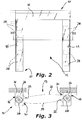
Figure 2 is a front elevational view ofFigure 1 , from the side indicated by arrow II ofFigure 1 ; -
Figure 3 is a schematic top elevational view sectioned along the line III-III ofFigure 2 , of a device for generating an air blade barrier according to a first embodiment of the invention; -
Figures 4 and 5 are views similar toFigures 1 and2 , respectively, of a device for generating an air blade barrier to which a movable closure member is associated, for example consisting of a flexible and rolling curtain; -
Figure 6 is a schematic top elevational view sectioned along the line VI-VI ofFigure 5 , showing a device for generating an air blade barrier according to another embodiment of the invention; -
Figures 7 and 8 are front elevational views of each of the uprights of the door ofFigure 6 , from the side of arrows VII and VIII, respectively; -
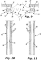
Figure 9 is a view similar toFigure 6 , of a device according to a third embodiment of the invention; -
Figures 10 and 11 are front elevational views of each of the uprights of the door ofFigure 9 , from the side of arrows X and XI, respectively; -
Figure 12 is a view similar toFigure 6 , of a device according to a fourth embodiment of the invention; -
Figures 13 and 14 are front elevational views of each of the uprights of the door ofFigure 12 , from the side of arrows XIII and XIV, respectively; -
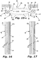
Figure 15 is a view similar toFigure 3 , of a device according to a fifth embodiment of the invention; -
Figures 16 and 17 are front elevational views of the uprights of the door ofFigure 15 , from the side of arrows XVI and XVII, respectively; and -
Figures 18 and 19 are front elevational views of each of the uprights of a device of the invention according to a possible modification. - With initial reference to
Figures 1 to 3 of the drawings, a device for generating an air blade barrier according to a first embodiment of the invention comprises a portal structure indicated 10 as a whole. Thestructure 10 defines apassage 12 between a pair of oppositevertical uprights upper cross member 18 which is connected to the upper ends of theuprights base plane 20. - Each upright 14, 16 has an
inner cavity 26 in which a series ofrespective fans 28 are mounted, which are placed at different heights, thefans 28 being arranged symmetrically in the twouprights - The
inner cavity 26 of each upright 14, 16 communicates with thepassage 12 through an input opening preferably formed by aligned series ofholes 30, and an outlet opening in the form of alongitudinal slit 32. - In particular, each upright 14, 16 comprises a series of openings, or holes, 30 for entry of the air flow, and a
respective slit 32 for the exit of the air flow, the series ofholes 30 and theslit 32 extending substantially parallel to the corresponding upright 14, 16. In the configuration of use of theportal structure 10, that is with theuprights holes 30 and theslit 32 of the upright 14 face directly theslit 32 and the series ofholes 30 of the upright 16, respectively. - Between the series of
holes 30 of an upright and theslit 32 of the opposite upright, a continuous air flow is generated which constitutes a corresponding air blade barrier indicated 33 and 35 inFigure 3 . - In the operation, and as a result of the activation of the
fans 28, an air flow is sucked into theinner cavity 26 of theuprights passage 12 through the respective series ofholes 30. The sucked air flow is then ejected by thevarious fans 28 by means of a common diffuser for each upright 14, 16, which has alongitudinal slit 32 so as to allow a corresponding continuousair blade barrier air blade barriers slits 32 of theuprights passage 12 with opposite directions of flow, creating a pair of independent air flows at opposite areas of thepassage 12 of thestructure 10, which constitute together a double air blade barrier. In this manner, a good seal is achieved towards the heat exchanges between the two adjacent environments to be isolated to each other, that is between the two environments upstream and downstream of theportal structure 10. The twoair blade barriers passage 12. - By selectively adjusting the speed of the pairs of
fans 28 placed at the same height in the twouprights portal structure 10, in order to obtain a series of desired effects, for example to better compensate the heat exchange between the two environments in areas located at different height of the portal structure, and/or to modify the intensity of the air flow at specific zones of thepassage 12, for example at an area close to that of the head of the users in order to improve the comfort of the users passing through theflow passage 12. - With reference to
Figures 4 to 8 of the drawings, another embodiment of the invention comprises thesame portal structure 10 already described for the previous embodiment, to which amovable closure member 22 is associated, for example consisting of at least one flexible and vertically slidable curtain, for closing thepassage 12. Typically, theflexible curtain 22 is made by means of a continuous sheet of plastic or plasticized textile material, having a transverse upper edge secured, in a per se known manner, to a rotatable winding shaft (not shown) housed inside thecross member 18. The rotation of the winding shaft about its own axis is controlled by a motorized control unit that can be operated by a user, for example by means of one ormore control buttons 23, by means of which the quick rising and descent of thecurtain 22 into thepassage 12 can be controlled, which forms in this manner a closure of the "quick sliding" type, that is in which opening and closing are performed with a relatively high speed, or by an automatic control including sensors of a known type adapted to detect the passage of a body in the vicinity of thepassage 12. Despite this, themovable closure member 22 could be different from the curtain considered above, and be movable with respect to the opening 12 in a not quick manner, according to a conventional operation. - To allow the movement of the
closure member 22, the device comprises a pair ofguide rails 24, each of which is rigidly connected to a respective vertical upright 14, 16, in which the opposite side edges of thecurtain 22 are slidably engaged. - In particular, the
guide rail 24 of the upright 14 is arranged in a position more adjacent to the upstream environment with respect to theportal structure 10. Anelongated slit 32 extending longitudinally along the respective upright in order to allow the air flow to exit, is formed at a position parallel to and spaced from saidrail 24, a series of inlet openings, or holes, 30 being interposed between therail 24 and theslit 32. The opposite upright 16 also includes aguide rail 24 facing theguide rail 24 of the upright 14, which extends longitudinally with respect to the relevant upright and a series of inlet openings, or holes, 30, in a position parallel to and spaced therefrom, a respectiveelongated slit 32 being interposed between therail 24 and the series ofholes 30. - In the operation of this embodiment, as a result of the activation of the
fans 28, an air flow is sucked into theinner cavity 26 of theuprights passage 12 through the relevant series ofholes 30. The sucked air flow is then ejected from thevarious fans 28 into thepassage 12 by means of a common diffuser for each upright 14, 16, through alongitudinal slit 32 so as to allow a pair of continuous and independent air blade barriers to be created, indicated by 34 and 36 inFigure 6 , at thepassage 12. The twoair blade barriers slits 32, pass through thepassage 12 along opposite directions of flow and at respective positions substantially adjacent to thecurtain 22, which allows an optimum seal to be obtained towards the heat exchanges between the upstream and downstream environments of thecurtain 22, also when thecurtain 22 is raised to allow passing through thepassage 12. The twoair blade barriers passage 12, which enables a better seal of thermal exchanges, and allows also to confine effectively possible impurities or foreign agents present in the air flow. - By selectively adjusting the speed of the pairs of
fans 28 placed at the same height in the twouprights door 10, so as to better oppose the heat exchange between the two environments at areas located at different height of the portal structure, and/or to change the intensity of the flow during raising of thecurtain 22 and when it is fully raised, and/or to modify the intensity of the air flow at specific zones of thepassage 12, as already described for the previous embodiment. - In this manner, at least one of the air blade barriers laps at least partially onto the
closure member 22, or a zone adjacent to it, thus preventing a direct contact between this closure member and the air of the environment downstream of the portal structure, thus limiting the heat exchange between the two environments even when the closure member moves along the portal structure to allow the passage of persons and/or objects. - In a third embodiment of the invention shown in
Figures 9 to 11 , and without prejudice to the general characteristics already described above, each of theuprights respective guide rail 24 for the sliding engagement of the opposite edges of thecurtain 22. Moreover, an inlet opening consisting of the series ofholes 30 is formed in each upright 14, 16 on one side of therail 24, as well as a respectivelongitudinal slit 32 that constitutes the air flow outlet opening, at the opposite side of theguide rail 24. Since theuprights respective rails 24 placed at a central position, and the series ofholes 30 and the respectivelongitudinal slit 32 at respectively opposite positions, the two uprights have a symmetrical shape. - More particularly, the series of
holes 30, or air flow inlet openings, extends in a zone close to theguide rail 24 of each upright 14, 16, at an upstream side with respect to theguide rail 24, while the air flow output slit 32 extends in each upright 14, 16 on the downstream side with respect to theguide rail 24, so that the series of airflow inlet openings 30 and the air flow outlet slit 32 are arranged on each upright at opposite positions with respect to therelative guide rail 24, and facing the series ofapertures 30 and theslit 32 of the opposite upright. - In the operation, as a consequence of the activation of the
fans 28 of theuprights passage 12 through the series ofholes 30 of theuprights Figure 9 , which lap at least partially onto the side of thecurtain 22 facing the upstream environment. This air flow reaches the series offans 28 of theuprights longitudinal slit 32, thus providing a pair of halfair blade barriers 40 downstream of thecurtain 22, according to two flows that converge toward a central region of thepassage 12, which lap at least partially onto the downstream side of thecurtain 22. - The two air blade barriers thus formed, each consisting of a pair of half-
barriers 38 and 40, pass through thepassage 12 with generally opposite flow directions with respect to the plane of thepassage 12, and at a position substantially adjacent to the opposite sides of thecurtain 22, which allows an optimum seal to be obtained towards the heat exchanges between the environments upstream and downstream of thecurtain 22, even when thecurtain 22 is raised to allow the passage through thepassage 12. The air blade barriers each constituted by the two half-barriers 38 and 40 generate a continuous vortical circulation at the central part of thepassage 12, which allows to improve the seal against the heat exchanges between the two environments upstream and downstream of thecurtain 22, and to confine and/or effectively expel possible impurities or foreign agents present in the air flow. - In this case also, the speed of the pairs of
fans 28 placed at the same height in the twouprights passage 12 as a function of the height, for the same purposes mentioned above in connection with the previous embodiments. -
Figures 12 to 14 of the drawings show a fourth embodiment of the invention. In this case, and without prejudice to the general characteristics of the device described above, each upright 14, 16 has, at a substantially central position, arespective guide rail 24 for the slidable engagement of a corresponding edge of thecurtain 22. Eachupright holes 30, at one side of therespective rail 24, and a respectivelongitudinal slit 32 constituting the air flow outlet opening, at the opposite side of theguide rail 24 with respect to the series ofholes 30. In particular, the series ofholes 30 and the respectivelongitudinal slit 32 of the upright 14 are arranged at opposite sides with respect to the series ofholes 30 and to the respectivelongitudinal slit 32 of theupright 16. Therefore, as it can be seen fromFigures 10 and 11 , theuprights - The series of
holes 30, or air flow inlet openings, of each upright 14, 16 extend at a zone close and on the side of theguide rail 24, while the air flow output slit 32 extends in each upright 14, 16 on the side opposite to the series ofholes 30 with respect to theguide rail 24, the series of airflow inlet openings 30 and the air flow outlet slit 32 being provided on therelevant upright respective guide rail 24. - In the operation of the device according to this embodiment, the activation of the
fans 28 causes the suction of air flows from thepassage 12 to thehollow zone 26 of theuprights holes 30 of these uprights. These air flows indicated by 42 and 44 inFigure 12 , come out from theslits 32 of the twouprights fans 28, until they reach the series ofholes 30 of the opposite upright, after passing through thepassage 12, owing to the suction action performed by thefans 28. - Therefore, the
air flow 42 upstream of thecurtain 22 generates a first air blade that laps onto the side of thecurtain 22 facing the upstream environment, while theair flow 44 downstream of thecurtain 22 generates a second air blade that laps onto the side of thecurtain 22 facing the downstream environment, the two air blades having air flow directions opposite to one another. - In the lowered position of the
curtain 22, the twoair flows curtain 22. - The
double air flow barriers curtain 22, respectively, which form a continuous circulation of air that surrounds thecurtain 22, which makes it possible to keep separated the environments upstream and downstream of thecurtain 22 close to thepassage 12, and to prevent the access of foreign matters in the respective environments. - When the
curtain 22 is raised to open thepassage 12, the twoair blade barriers passage 12, which allows the seal to be made highly effective for the heat exchanges between the two environments, as well as to confine and/or expel any impurities or foreign agents present in the air flow. - In this case also, the speed of the pairs of
fans 28 placed at the same height in the twouprights passage 12 as a function of the height, for the same purposes mentioned above in connection with the previous embodiments. -
Figures 15 to 17 of the drawings show a fifth embodiment of the invention. In this case, and without prejudice to the general characteristics of the device described above, thepassage 12 defined by theportal structure 10 can be closed by a pair of parallelflexible curtains - The side edges of the two
curtains vertical guide rails 24, two ofsuch guide rails 24 being fixed to each of theuprights guide rails 24 of each upright 14, 16 there is a series of air flow inlet openings, or holes, 30 and an air flow outlet slit 32. - More particularly, each upright 14, 16, at its region interposed between the two
guide rails 24 thereof, comprises an inlet opening consisting of the series ofholes 30, and a respectivelongitudinal slit 32 that constitutes the air flow outlet opening. The series ofholes 30 and thelongitudinal slit 32 of arespective upright holes 30 and theslit 32 of the upright 14 face directly facing and are opposite to theslit 32 and to the series ofholes 30 of theupright 16, respectively. Therefore, as it can be seen inFigures 16 and 17 , theuprights - The
upright 14, at an area close to one of the guide rails 24 of thefirst curtain 22, that is of thecurtain 22 closest to the upstream environment, comprises the series of air flow inlet holes 30, and then the air flow outlet slit 32, after which thesecond guide rail 24 of theother curtain 22a, that is of the curtain arranged closest to the downstream environment with respect to the portal structure, extends, the twoguide rails 24 being parallel to each other. In a similar manner, theupright 16 comprises the air flow outlet slit 32 at a zone thereof close to one of the guide rails 24 of thefirst curtain 22, and then the series of air flow inlet holes 30, after which theguide rail 24 of theother curtain 22a is provided, also the twoguide rails 24 of the upright 16 being parallel to each other. In particular, the series of airflow suction openings 30 of anupright slit 32 of the air flow of the other upright, and vice-versa. - In this embodiment, a pair of air blade barriers having opposite direction are generated between the two parallel flexible curtains in their lowered and closed condition, each being adjacent to one of the faces of the two
flexible curtains curtains - In particular, a first air flow indicated by 46 in
Figure 15 , come out from theslit 32 of theupright 16 and, after having passed through thepassage 12, it is sucked through the series ofholes 30 of theother upright 14. This first air flow laps onto the downstream face of thecurtain 22 creating a first air blade barrier close to thecurtain 22. - A second air flow comes out from the
slit 32 of theupright 14 and, after having passed through thepassage 12, it is sucked by theother upright 16 through the respective series ofholes 30. This second air flow, indicated 48 inFigure 15 , laps onto the upstream face of thesecond curtain 22a creating a second air blade barrier in the vicinity of thecurtain 22a. - When the two
curtains passage 12, the twoair blade barriers 46 and 48 having opposite direction are adjacent, and their behavior and operation is similar to that described with reference to the second embodiment. The continuous air circulation of theflows 46 and 48 of the two air blade barriers generates a vortical circulation with a vertical axis arranged substantially at the center of thepassage 12, which allows the seal towards the heat exchanges between the two environments to be made highly effective, as well as any impurities or foreign agents present in the air flow to be confined and/or expelled. - In the raised configuration of only one of the
curtains curtains - Also in the case of the present embodiment, the speed of the pairs of
fans 28 placed at the same height in the twouprights passage 12 as a function of the height, for the same purposes mentioned above in connection with the previous embodiments. - With reference to
Figures 18 and 19 , there is schematically shown a modification of the structure of the side uprights 14, 16 of theportal structure 10, each of which is made by joining a pair of different sections indicated 14a, 14b and 16a, 16b, respectively. In particular, theuprights longitudinal part 14b and 16b, respectively, has a specular structure with respect to the upper longitudinal part. Each longitudinal upper or lower part of theuprights flow output slits fans 28 placed at thelower part 14b and 16b of theuprights fans 28 located at the upper part 14a and 16a, taking into account that eachfan 28 must have its own discharge conduit directed at therelative slit 32. - Although in these
Figures 18 and 19 the shape of theuprights guide rails 24 for the vertical sliding of the opposite edges of acurtain 22 has been considered, the configuration of these uprights in the case in which the device for generating an air blade barrier does not comprise a movable closure member, is achieved simply by eliminating thecurtain 22 and therespective guide rails 24, so as to be able to adapt it for the use with the device of the first embodiment described above. - The arrangement of this modification has the purpose of improving locally, in particular at different heights of the
portal structure 10, the seal against the positive or negative heat exchange between the two environments upstream and downstream of theportal structure 10, as a function of the height of theuprights - If, as often happens, the two environments to be isolated upstream and downstream of the
door 10 are at different temperatures, for example if the outer or downstream environment is hot and the inner or upstream environment is cold, in the absence of thecurtain 22 or in its raised condition, there will be a higher tendency of penetration into the inner environment of a hot air flow coming from the outer environment through the upper portion of the portal structure, while the cold air flow of the inner environment will tend more to penetrate into the outer environment through the lower portion of theportal structure 10. - Therefore, when the inner environment with respect to the
structure 10 is colder than the outer environment, and according to this modification, the upper part 14a, 16a of each upright 14, 16 sucks air from the colder inner environment and thus causes the formation of a usually colder pair of air barriers having opposite directions. Vice-versa, thelower part 14b, 16b of each upright 14, 16 sucks air from the hotter outer environment and causes the formation of a usually hotter pair of air barriers having opposite directions. In this manner it is possible to compensate at least in part the tendency of colder air of the inner environment to go out from the lower portion of thepassage 12, and the tendency of the hotter air of the outer environment to penetrate through the upper portion of thepassage 12 when thecurtain 22 is missing or is raised. - Of course, other combinations of parts of the
uprights
Claims (12)
- Device for generating an air blade barrier between two environments communicating with each other through a portal structure (10) that defines a passage (12), such a passage extending horizontally between a pair of opposite side uprights (14, 16) and vertically between an upper crosspiece (18) connected to such uprights (14, 16) at their upper ends, and a base plane (20), which uprights (14, 16) have an inner cavity (26) connected with said passage (12) and in which an air flow is admitted as a result of the operation of fan means (28) associated with the portal structure (10), a first upright (14, 16) having at least one inlet opening (30) to allow an air flow to be sucked from said passage (12), and a second upright (14, 16) having at least one outlet opening (32) to allow said air flow to exit in order to continuously generate said air blade barrier at said passage (12),
characterized in that said fan means (28) are incorporated in each of said uprights (14, 16), in that each upright (14, 16) comprises both said air flow inlet opening (30) and said air flow outlet opening (32), and in that the device allows a pair of independent air flows to be generated at said passage (12), at opposite zones of the passage (12) of the portal structure, which air flows create together a double air blade barrier. - Device according to claim 1, characterized in that a series of fans (28) is mounted in each upright (14, 16), which series comprises fans (28) arranged at different heights with respect to the portal structure (10), the fans (28) of each upright (14, 16) being arranged symmetrically with respect to the fans (28) of the other upright (14, 16).
- Device according to claim 2, characterized in that the speed of the air flow delivered by a pair of fans (28) arranged at the same height in the two uprights (14, 16), is selectively controlled so that the respective air blade barrier portions generated by them are adapted to compensate for the heat exchange at that height.
- Device according to any one of Claims 1 to 3, characterized in that it comprises at least one slidable closure member (22; 22, 22a) for closing said passage (12), each upright (14, 16) comprising at least one vertical guide rail (24) for guiding the sliding of a side edge of said at least one closure member (22; 22, 22a), and in that said two air blade barriers (34, 36; 46, 48) generate a pair of air flows having opposite directions, both of which are arranged adjacent to said at least one closure member (22; 22, 22a).
- Device according to claim 4, characterized in that said at least one closure member consists of a quick sliding flexible curtain (22; 22, 22a), which is adapted to be wound, in the closed condition of the door (10), about a motorized rotary shaft that extends along the upper crosspiece (18) of said structure.
- Device according to claim 4 or 5, characterized in that said two air blade barriers (34, 36; 46, 48) are both arranged on a same side of said at least one closure member (22; 22, 22a).
- Device according to claim 6, characterized in that a first vertical upright (14) comprises a first vertical guide rail (24) for the sliding engagement by a side edge of a respective flexible curtain (22; 22, 22a) and, in a position parallel and spaced apart from said first guide rail (24), said air flow outlet opening, which is made in the form of a first slit (32) parallel to said first guide rail (24), a first series of air flow inlet openings (30) being interposed between said first guide rail (24) and said first slit (32), and in that a second vertical upright (16) comprises a second vertical guide rail (24) for guiding a respective side edge of a respective flexible curtain (22; 22, 22a) and, in a position parallel and spaced apart from said second guide rail (24), a second series of air flow inlet openings (30), an air flow outlet opening, which is made in the form of a second slit (32) parallel to said second guide rail (24), being interposed between said second guide rail (24) and said second series of air flow inlet openings (30).
- Device according to claim 4 or 5, characterized in that said double air blade barrier consists of a first air blade barrier (38; 42) arranged on the side of a first side of said closure member (22, 22, 22a), and of a second air blade barrier (40; 44) arranged on the side of a second side of said closure member (22; 22, 22a).
- Device according to claim 8, characterized in that said series of air flow inlet openings (30) and said air flow outlet slit (32) are arranged in said uprights (14, 16) on opposite sides of the respective guide rail (24).
- Device according to claim 8, characterized in that said series of air flow inlet openings (30) and said air flow outlet slit (32) are arranged in both the uprights (14, 16) according to a symmetrical configuration, on the same side with respect to the respective guide rail (24).
- Device according to claim 4 or 5, characterized in that each upright (14, 16) comprises a pair of vertical guide rails (24) for the slidable engagement of the side edges of a pair of closure members (22, 22a), a series of inlet air flow openings (30) and an air flow outlet slit (32) being provided in each upright (14, 16) between said pair of guide rails (24), which are arranged in such a manner that the series of air flow inlet openings (30) of an upright (14, 16) faces directly the air flow outlet slit (32) of the other upright (14, 16) and vice-versa, so that a pair of air blade barriers having opposite directions are generated between the two parallel flexible curtains (22, 22a) in their closed condition, each air blade barrier being adjacent to one of the mutually facing sides of said two closure members (22, 22a).
- Quick-sliding door according to any one of claims 1 to 11, characterized in that each upright (14, 16) includes at least two longitudinal portions (14a, 14b), each of which has its respective series of air flow inlet openings (30) and the respective air flow outlet slit (32) arranged on mutually opposite sides, with the purpose to compensate locally for a positive or a negative heat exchange depending on its position in height with respect to the respective upright (14, 16).
Applications Claiming Priority (1)
| Application Number | Priority Date | Filing Date | Title |
|---|---|---|---|
| IT102019000011145A IT201900011145A1 (en) | 2019-07-08 | 2019-07-08 | DEVICE FOR THE GENERATION OF AN AIR CURTAIN |
Publications (2)
| Publication Number | Publication Date |
|---|---|
| EP3764006A1 true EP3764006A1 (en) | 2021-01-13 |
| EP3764006B1 EP3764006B1 (en) | 2023-12-27 |
Family
ID=68501905
Family Applications (1)
| Application Number | Title | Priority Date | Filing Date |
|---|---|---|---|
| EP20000239.2A Active EP3764006B1 (en) | 2019-07-08 | 2020-07-03 | Device for generating an air blade barrier |
Country Status (3)
| Country | Link |
|---|---|
| EP (1) | EP3764006B1 (en) |
| ES (1) | ES2977902T3 (en) |
| IT (1) | IT201900011145A1 (en) |
Cited By (2)
| Publication number | Priority date | Publication date | Assignee | Title |
|---|---|---|---|---|
| CN114575724A (en) * | 2022-03-25 | 2022-06-03 | 青岛拉斐特智能装备科技有限公司 | Flat-open cold storage door with anticollision function |
| US12078365B2 (en) | 2022-01-28 | 2024-09-03 | Samsung Electronics Co., Ltd. | Outdoor unit of airconditioner |
Citations (6)
| Publication number | Priority date | Publication date | Assignee | Title |
|---|---|---|---|---|
| GB1155880A (en) * | 1966-12-08 | 1969-06-25 | Firth Cleveland Ltd | Improvements relating to Air Curtain Apparatus |
| US3859900A (en) * | 1972-02-11 | 1975-01-14 | Marc Fordsmand | Air curtain system |
| DE10005964A1 (en) * | 2000-02-09 | 2001-08-23 | Kessler & Luch Gmbh & Co Kg | Draft air entry prevention device for aperture in building has fan or compressed air device spaced out by air gap from building |
| GB2397116A (en) | 2003-01-14 | 2004-07-14 | Clark Door Ltd | Conditioned vestibule for a cold storage doorway |
| JP2006057928A (en) * | 2004-08-20 | 2006-03-02 | Mayekawa Mfg Co Ltd | Insect and dust protecting air shutter |
| WO2007117017A1 (en) * | 2006-04-05 | 2007-10-18 | Mayekawa Mfg. Co., Ltd. | Air shutter and installation method thereof |
-
2019
- 2019-07-08 IT IT102019000011145A patent/IT201900011145A1/en unknown
-
2020
- 2020-07-03 ES ES20000239T patent/ES2977902T3/en active Active
- 2020-07-03 EP EP20000239.2A patent/EP3764006B1/en active Active
Patent Citations (6)
| Publication number | Priority date | Publication date | Assignee | Title |
|---|---|---|---|---|
| GB1155880A (en) * | 1966-12-08 | 1969-06-25 | Firth Cleveland Ltd | Improvements relating to Air Curtain Apparatus |
| US3859900A (en) * | 1972-02-11 | 1975-01-14 | Marc Fordsmand | Air curtain system |
| DE10005964A1 (en) * | 2000-02-09 | 2001-08-23 | Kessler & Luch Gmbh & Co Kg | Draft air entry prevention device for aperture in building has fan or compressed air device spaced out by air gap from building |
| GB2397116A (en) | 2003-01-14 | 2004-07-14 | Clark Door Ltd | Conditioned vestibule for a cold storage doorway |
| JP2006057928A (en) * | 2004-08-20 | 2006-03-02 | Mayekawa Mfg Co Ltd | Insect and dust protecting air shutter |
| WO2007117017A1 (en) * | 2006-04-05 | 2007-10-18 | Mayekawa Mfg. Co., Ltd. | Air shutter and installation method thereof |
Cited By (2)
| Publication number | Priority date | Publication date | Assignee | Title |
|---|---|---|---|---|
| US12078365B2 (en) | 2022-01-28 | 2024-09-03 | Samsung Electronics Co., Ltd. | Outdoor unit of airconditioner |
| CN114575724A (en) * | 2022-03-25 | 2022-06-03 | 青岛拉斐特智能装备科技有限公司 | Flat-open cold storage door with anticollision function |
Also Published As
| Publication number | Publication date |
|---|---|
| IT201900011145A1 (en) | 2021-01-08 |
| ES2977902T3 (en) | 2024-09-02 |
| EP3764006B1 (en) | 2023-12-27 |
Similar Documents
| Publication | Publication Date | Title |
|---|---|---|
| EP3764006B1 (en) | Device for generating an air blade barrier | |
| EP1439353B1 (en) | Conditioned vestibule for a cold storage doorway | |
| EP0476364B1 (en) | Baking oven | |
| CN107250674B (en) | air conditioner | |
| JP7252000B2 (en) | Air curtain generator | |
| KR102011425B1 (en) | Ventilation structure for kitchen range | |
| DE10007004B4 (en) | Method for guiding a material web and heat treatment device | |
| CA2155026A1 (en) | Ventilation device | |
| DE10224527A1 (en) | sliding device | |
| JP4310739B2 (en) | Sliding door device | |
| CA1091985A (en) | Apparatus for guiding work through a sewing machine or the like | |
| CH674994A5 (en) | ||
| KR20200056024A (en) | Duct apparatus and ventilation system | |
| DE2435138A1 (en) | Baking oven having reduced width and depth - with horizontal non-turbulent air flow for consistent quality product | |
| DE1561642C3 (en) | Device for influencing the air flow conditions in the drying section of a paper machine | |
| DE202011004136U1 (en) | Device for ventilating, heating and / or cooling a room | |
| KR100640146B1 (en) | Elevator Differential Pressure Reduction Device | |
| WO2003027577A1 (en) | Supply air terminal device | |
| DE102004047993A1 (en) | oven | |
| EP2498017B1 (en) | Method for ventilating, heating and/or cooling a room and device for same | |
| EP3963268B1 (en) | An active airflow inhibiting apparatus | |
| FI74799C (en) | An air supply device. | |
| JP3769471B2 (en) | Web heat treatment equipment | |
| SU1712743A1 (en) | Device for creating air curtain in gate opening | |
| DE102008033536A1 (en) | Baking-oven, has oven door with air lock that is automatically adjustable by actuator depending on respective thermal mode of operation of oven for achieving different flow strengths in flow path, and control unit for controlling actuator |
Legal Events
| Date | Code | Title | Description |
|---|---|---|---|
| PUAI | Public reference made under article 153(3) epc to a published international application that has entered the european phase |
Free format text: ORIGINAL CODE: 0009012 |
|
| STAA | Information on the status of an ep patent application or granted ep patent |
Free format text: STATUS: THE APPLICATION HAS BEEN PUBLISHED |
|
| AK | Designated contracting states |
Kind code of ref document: A1 Designated state(s): AL AT BE BG CH CY CZ DE DK EE ES FI FR GB GR HR HU IE IS IT LI LT LU LV MC MK MT NL NO PL PT RO RS SE SI SK SM TR |
|
| AX | Request for extension of the european patent |
Extension state: BA ME |
|
| STAA | Information on the status of an ep patent application or granted ep patent |
Free format text: STATUS: REQUEST FOR EXAMINATION WAS MADE |
|
| 17P | Request for examination filed |
Effective date: 20210707 |
|
| RBV | Designated contracting states (corrected) |
Designated state(s): AL AT BE BG CH CY CZ DE DK EE ES FI FR GB GR HR HU IE IS IT LI LT LU LV MC MK MT NL NO PL PT RO RS SE SI SK SM TR |
|
| STAA | Information on the status of an ep patent application or granted ep patent |
Free format text: STATUS: EXAMINATION IS IN PROGRESS |
|
| 17Q | First examination report despatched |
Effective date: 20220421 |
|
| RAP1 | Party data changed (applicant data changed or rights of an application transferred) |
Owner name: BMPEUROPE S.R.L. |
|
| P01 | Opt-out of the competence of the unified patent court (upc) registered |
Effective date: 20230603 |
|
| GRAP | Despatch of communication of intention to grant a patent |
Free format text: ORIGINAL CODE: EPIDOSNIGR1 |
|
| STAA | Information on the status of an ep patent application or granted ep patent |
Free format text: STATUS: GRANT OF PATENT IS INTENDED |
|
| RIC1 | Information provided on ipc code assigned before grant |
Ipc: E06B 9/02 20060101ALI20230629BHEP Ipc: F25D 23/02 20060101ALI20230629BHEP Ipc: E06B 9/11 20060101ALI20230629BHEP Ipc: F24F 13/072 20060101ALI20230629BHEP Ipc: F24F 13/06 20060101ALI20230629BHEP Ipc: F24F 9/00 20060101AFI20230629BHEP |
|
| INTG | Intention to grant announced |
Effective date: 20230719 |
|
| GRAS | Grant fee paid |
Free format text: ORIGINAL CODE: EPIDOSNIGR3 |
|
| GRAA | (expected) grant |
Free format text: ORIGINAL CODE: 0009210 |
|
| STAA | Information on the status of an ep patent application or granted ep patent |
Free format text: STATUS: THE PATENT HAS BEEN GRANTED |
|
| AK | Designated contracting states |
Kind code of ref document: B1 Designated state(s): AL AT BE BG CH CY CZ DE DK EE ES FI FR GB GR HR HU IE IS IT LI LT LU LV MC MK MT NL NO PL PT RO RS SE SI SK SM TR |
|
| REG | Reference to a national code |
Ref country code: GB Ref legal event code: FG4D |
|
| REG | Reference to a national code |
Ref country code: CH Ref legal event code: EP |
|
| REG | Reference to a national code |
Ref country code: DE Ref legal event code: R096 Ref document number: 602020023233 Country of ref document: DE |
|
| REG | Reference to a national code |
Ref country code: IE Ref legal event code: FG4D |
|
| PG25 | Lapsed in a contracting state [announced via postgrant information from national office to epo] |
Ref country code: GR Free format text: LAPSE BECAUSE OF FAILURE TO SUBMIT A TRANSLATION OF THE DESCRIPTION OR TO PAY THE FEE WITHIN THE PRESCRIBED TIME-LIMIT Effective date: 20240328 |
|
| REG | Reference to a national code |
Ref country code: NL Ref legal event code: FP Ref country code: LT Ref legal event code: MG9D |
|
| PG25 | Lapsed in a contracting state [announced via postgrant information from national office to epo] |
Ref country code: LT Free format text: LAPSE BECAUSE OF FAILURE TO SUBMIT A TRANSLATION OF THE DESCRIPTION OR TO PAY THE FEE WITHIN THE PRESCRIBED TIME-LIMIT Effective date: 20231227 |
|
| PG25 | Lapsed in a contracting state [announced via postgrant information from national office to epo] |
Ref country code: LT Free format text: LAPSE BECAUSE OF FAILURE TO SUBMIT A TRANSLATION OF THE DESCRIPTION OR TO PAY THE FEE WITHIN THE PRESCRIBED TIME-LIMIT Effective date: 20231227 Ref country code: GR Free format text: LAPSE BECAUSE OF FAILURE TO SUBMIT A TRANSLATION OF THE DESCRIPTION OR TO PAY THE FEE WITHIN THE PRESCRIBED TIME-LIMIT Effective date: 20240328 Ref country code: FI Free format text: LAPSE BECAUSE OF FAILURE TO SUBMIT A TRANSLATION OF THE DESCRIPTION OR TO PAY THE FEE WITHIN THE PRESCRIBED TIME-LIMIT Effective date: 20231227 Ref country code: BG Free format text: LAPSE BECAUSE OF FAILURE TO SUBMIT A TRANSLATION OF THE DESCRIPTION OR TO PAY THE FEE WITHIN THE PRESCRIBED TIME-LIMIT Effective date: 20240327 |
|
| REG | Reference to a national code |
Ref country code: AT Ref legal event code: MK05 Ref document number: 1644858 Country of ref document: AT Kind code of ref document: T Effective date: 20231227 |
|
| PG25 | Lapsed in a contracting state [announced via postgrant information from national office to epo] |
Ref country code: SE Free format text: LAPSE BECAUSE OF FAILURE TO SUBMIT A TRANSLATION OF THE DESCRIPTION OR TO PAY THE FEE WITHIN THE PRESCRIBED TIME-LIMIT Effective date: 20231227 Ref country code: RS Free format text: LAPSE BECAUSE OF FAILURE TO SUBMIT A TRANSLATION OF THE DESCRIPTION OR TO PAY THE FEE WITHIN THE PRESCRIBED TIME-LIMIT Effective date: 20231227 Ref country code: NO Free format text: LAPSE BECAUSE OF FAILURE TO SUBMIT A TRANSLATION OF THE DESCRIPTION OR TO PAY THE FEE WITHIN THE PRESCRIBED TIME-LIMIT Effective date: 20240327 Ref country code: LV Free format text: LAPSE BECAUSE OF FAILURE TO SUBMIT A TRANSLATION OF THE DESCRIPTION OR TO PAY THE FEE WITHIN THE PRESCRIBED TIME-LIMIT Effective date: 20231227 Ref country code: HR Free format text: LAPSE BECAUSE OF FAILURE TO SUBMIT A TRANSLATION OF THE DESCRIPTION OR TO PAY THE FEE WITHIN THE PRESCRIBED TIME-LIMIT Effective date: 20231227 |
|
| PG25 | Lapsed in a contracting state [announced via postgrant information from national office to epo] |
Ref country code: IS Free format text: LAPSE BECAUSE OF FAILURE TO SUBMIT A TRANSLATION OF THE DESCRIPTION OR TO PAY THE FEE WITHIN THE PRESCRIBED TIME-LIMIT Effective date: 20240427 |
|
| PG25 | Lapsed in a contracting state [announced via postgrant information from national office to epo] |
Ref country code: AT Free format text: LAPSE BECAUSE OF FAILURE TO SUBMIT A TRANSLATION OF THE DESCRIPTION OR TO PAY THE FEE WITHIN THE PRESCRIBED TIME-LIMIT Effective date: 20231227 Ref country code: CZ Free format text: LAPSE BECAUSE OF FAILURE TO SUBMIT A TRANSLATION OF THE DESCRIPTION OR TO PAY THE FEE WITHIN THE PRESCRIBED TIME-LIMIT Effective date: 20231227 |
|
| PG25 | Lapsed in a contracting state [announced via postgrant information from national office to epo] |
Ref country code: SK Free format text: LAPSE BECAUSE OF FAILURE TO SUBMIT A TRANSLATION OF THE DESCRIPTION OR TO PAY THE FEE WITHIN THE PRESCRIBED TIME-LIMIT Effective date: 20231227 |
|
| PG25 | Lapsed in a contracting state [announced via postgrant information from national office to epo] |
Ref country code: SM Free format text: LAPSE BECAUSE OF FAILURE TO SUBMIT A TRANSLATION OF THE DESCRIPTION OR TO PAY THE FEE WITHIN THE PRESCRIBED TIME-LIMIT Effective date: 20231227 Ref country code: SK Free format text: LAPSE BECAUSE OF FAILURE TO SUBMIT A TRANSLATION OF THE DESCRIPTION OR TO PAY THE FEE WITHIN THE PRESCRIBED TIME-LIMIT Effective date: 20231227 Ref country code: RO Free format text: LAPSE BECAUSE OF FAILURE TO SUBMIT A TRANSLATION OF THE DESCRIPTION OR TO PAY THE FEE WITHIN THE PRESCRIBED TIME-LIMIT Effective date: 20231227 Ref country code: IS Free format text: LAPSE BECAUSE OF FAILURE TO SUBMIT A TRANSLATION OF THE DESCRIPTION OR TO PAY THE FEE WITHIN THE PRESCRIBED TIME-LIMIT Effective date: 20240427 Ref country code: EE Free format text: LAPSE BECAUSE OF FAILURE TO SUBMIT A TRANSLATION OF THE DESCRIPTION OR TO PAY THE FEE WITHIN THE PRESCRIBED TIME-LIMIT Effective date: 20231227 Ref country code: CZ Free format text: LAPSE BECAUSE OF FAILURE TO SUBMIT A TRANSLATION OF THE DESCRIPTION OR TO PAY THE FEE WITHIN THE PRESCRIBED TIME-LIMIT Effective date: 20231227 Ref country code: AT Free format text: LAPSE BECAUSE OF FAILURE TO SUBMIT A TRANSLATION OF THE DESCRIPTION OR TO PAY THE FEE WITHIN THE PRESCRIBED TIME-LIMIT Effective date: 20231227 |
|
| PG25 | Lapsed in a contracting state [announced via postgrant information from national office to epo] |
Ref country code: PT Free format text: LAPSE BECAUSE OF FAILURE TO SUBMIT A TRANSLATION OF THE DESCRIPTION OR TO PAY THE FEE WITHIN THE PRESCRIBED TIME-LIMIT Effective date: 20240429 Ref country code: PL Free format text: LAPSE BECAUSE OF FAILURE TO SUBMIT A TRANSLATION OF THE DESCRIPTION OR TO PAY THE FEE WITHIN THE PRESCRIBED TIME-LIMIT Effective date: 20231227 |
|
| PG25 | Lapsed in a contracting state [announced via postgrant information from national office to epo] |
Ref country code: PT Free format text: LAPSE BECAUSE OF FAILURE TO SUBMIT A TRANSLATION OF THE DESCRIPTION OR TO PAY THE FEE WITHIN THE PRESCRIBED TIME-LIMIT Effective date: 20240429 Ref country code: PL Free format text: LAPSE BECAUSE OF FAILURE TO SUBMIT A TRANSLATION OF THE DESCRIPTION OR TO PAY THE FEE WITHIN THE PRESCRIBED TIME-LIMIT Effective date: 20231227 |
|
| REG | Reference to a national code |
Ref country code: ES Ref legal event code: FG2A Ref document number: 2977902 Country of ref document: ES Kind code of ref document: T3 Effective date: 20240902 |
|
| REG | Reference to a national code |
Ref country code: DE Ref legal event code: R097 Ref document number: 602020023233 Country of ref document: DE |
|
| PG25 | Lapsed in a contracting state [announced via postgrant information from national office to epo] |
Ref country code: DK Free format text: LAPSE BECAUSE OF FAILURE TO SUBMIT A TRANSLATION OF THE DESCRIPTION OR TO PAY THE FEE WITHIN THE PRESCRIBED TIME-LIMIT Effective date: 20231227 |
|
| PG25 | Lapsed in a contracting state [announced via postgrant information from national office to epo] |
Ref country code: DK Free format text: LAPSE BECAUSE OF FAILURE TO SUBMIT A TRANSLATION OF THE DESCRIPTION OR TO PAY THE FEE WITHIN THE PRESCRIBED TIME-LIMIT Effective date: 20231227 |
|
| PLBE | No opposition filed within time limit |
Free format text: ORIGINAL CODE: 0009261 |
|
| STAA | Information on the status of an ep patent application or granted ep patent |
Free format text: STATUS: NO OPPOSITION FILED WITHIN TIME LIMIT |
|
| 26N | No opposition filed |
Effective date: 20240930 |
|
| PG25 | Lapsed in a contracting state [announced via postgrant information from national office to epo] |
Ref country code: MC Free format text: LAPSE BECAUSE OF FAILURE TO SUBMIT A TRANSLATION OF THE DESCRIPTION OR TO PAY THE FEE WITHIN THE PRESCRIBED TIME-LIMIT Effective date: 20231227 |
|
| REG | Reference to a national code |
Ref country code: CH Ref legal event code: PL |
|
| PG25 | Lapsed in a contracting state [announced via postgrant information from national office to epo] |
Ref country code: LU Free format text: LAPSE BECAUSE OF NON-PAYMENT OF DUE FEES Effective date: 20240703 |
|
| PG25 | Lapsed in a contracting state [announced via postgrant information from national office to epo] |
Ref country code: LU Free format text: LAPSE BECAUSE OF NON-PAYMENT OF DUE FEES Effective date: 20240703 |
|
| PG25 | Lapsed in a contracting state [announced via postgrant information from national office to epo] |
Ref country code: CH Free format text: LAPSE BECAUSE OF NON-PAYMENT OF DUE FEES Effective date: 20240731 Ref country code: SI Free format text: LAPSE BECAUSE OF FAILURE TO SUBMIT A TRANSLATION OF THE DESCRIPTION OR TO PAY THE FEE WITHIN THE PRESCRIBED TIME-LIMIT Effective date: 20231227 |
|
| PGFP | Annual fee paid to national office [announced via postgrant information from national office to epo] |
Ref country code: GB Payment date: 20250612 Year of fee payment: 6 |
|
| PG25 | Lapsed in a contracting state [announced via postgrant information from national office to epo] |
Ref country code: IE Free format text: LAPSE BECAUSE OF NON-PAYMENT OF DUE FEES Effective date: 20240703 |
|
| PGFP | Annual fee paid to national office [announced via postgrant information from national office to epo] |
Ref country code: NL Payment date: 20250710 Year of fee payment: 6 |
|
| PGFP | Annual fee paid to national office [announced via postgrant information from national office to epo] |
Ref country code: ES Payment date: 20250804 Year of fee payment: 6 |
|
| PGFP | Annual fee paid to national office [announced via postgrant information from national office to epo] |
Ref country code: DE Payment date: 20250730 Year of fee payment: 6 |
|
| PGFP | Annual fee paid to national office [announced via postgrant information from national office to epo] |
Ref country code: BE Payment date: 20250728 Year of fee payment: 6 |
|
| PGFP | Annual fee paid to national office [announced via postgrant information from national office to epo] |
Ref country code: FR Payment date: 20250707 Year of fee payment: 6 |
|
| PG25 | Lapsed in a contracting state [announced via postgrant information from national office to epo] |
Ref country code: CY Free format text: LAPSE BECAUSE OF FAILURE TO SUBMIT A TRANSLATION OF THE DESCRIPTION OR TO PAY THE FEE WITHIN THE PRESCRIBED TIME-LIMIT; INVALID AB INITIO Effective date: 20200703 |
|
| PG25 | Lapsed in a contracting state [announced via postgrant information from national office to epo] |
Ref country code: HU Free format text: LAPSE BECAUSE OF FAILURE TO SUBMIT A TRANSLATION OF THE DESCRIPTION OR TO PAY THE FEE WITHIN THE PRESCRIBED TIME-LIMIT; INVALID AB INITIO Effective date: 20200703 |
|
| PG25 | Lapsed in a contracting state [announced via postgrant information from national office to epo] |
Ref country code: TR Free format text: LAPSE BECAUSE OF FAILURE TO SUBMIT A TRANSLATION OF THE DESCRIPTION OR TO PAY THE FEE WITHIN THE PRESCRIBED TIME-LIMIT Effective date: 20231227 |
|
| PGFP | Annual fee paid to national office [announced via postgrant information from national office to epo] |
Ref country code: IT Payment date: 20260520 Year of fee payment: 7 |