EP3763998A1 - Control element for a user interface of a domestic appliance - Google Patents
Control element for a user interface of a domestic appliance Download PDFInfo
- Publication number
- EP3763998A1 EP3763998A1 EP19185904.0A EP19185904A EP3763998A1 EP 3763998 A1 EP3763998 A1 EP 3763998A1 EP 19185904 A EP19185904 A EP 19185904A EP 3763998 A1 EP3763998 A1 EP 3763998A1
- Authority
- EP
- European Patent Office
- Prior art keywords
- control element
- user interface
- glass panel
- sensor element
- sensor
- Prior art date
- Legal status (The legal status is an assumption and is not a legal conclusion. Google has not performed a legal analysis and makes no representation as to the accuracy of the status listed.)
- Withdrawn
Links
Images


Classifications
-
- F—MECHANICAL ENGINEERING; LIGHTING; HEATING; WEAPONS; BLASTING
- F24—HEATING; RANGES; VENTILATING
- F24C—DOMESTIC STOVES OR RANGES ; DETAILS OF DOMESTIC STOVES OR RANGES, OF GENERAL APPLICATION
- F24C7/00—Stoves or ranges heated by electric energy
- F24C7/08—Arrangement or mounting of control or safety devices
- F24C7/082—Arrangement or mounting of control or safety devices on ranges, e.g. control panels, illumination
- F24C7/083—Arrangement or mounting of control or safety devices on ranges, e.g. control panels, illumination on tops, hot plates
-
- H—ELECTRICITY
- H02—GENERATION; CONVERSION OR DISTRIBUTION OF ELECTRIC POWER
- H02J—CIRCUIT ARRANGEMENTS OR SYSTEMS FOR SUPPLYING OR DISTRIBUTING ELECTRIC POWER; SYSTEMS FOR STORING ELECTRIC ENERGY
- H02J50/00—Circuit arrangements or systems for wireless supply or distribution of electric power
- H02J50/10—Circuit arrangements or systems for wireless supply or distribution of electric power using inductive coupling
-
- H—ELECTRICITY
- H03—ELECTRONIC CIRCUITRY
- H03K—PULSE TECHNIQUE
- H03K2217/00—Indexing scheme related to electronic switching or gating, i.e. not by contact-making or -breaking covered by H03K17/00
- H03K2217/94—Indexing scheme related to electronic switching or gating, i.e. not by contact-making or -breaking covered by H03K17/00 characterised by the way in which the control signal is generated
- H03K2217/94057—Rotary switches
- H03K2217/94068—Rotary switches with magnetic detection
-
- H—ELECTRICITY
- H03—ELECTRONIC CIRCUITRY
- H03K—PULSE TECHNIQUE
- H03K2217/00—Indexing scheme related to electronic switching or gating, i.e. not by contact-making or -breaking covered by H03K17/00
- H03K2217/94—Indexing scheme related to electronic switching or gating, i.e. not by contact-making or -breaking covered by H03K17/00 characterised by the way in which the control signal is generated
- H03K2217/96—Touch switches
- H03K2217/9607—Capacitive touch switches
- H03K2217/960785—Capacitive touch switches with illumination
Definitions
- the present invention relates to a control element for a user interface of a domestic appliance, in particular a cooking hob. Further, the present invention relates to a user interface of a domestic appliance, in particular a cooking hob. Moreover, the present invention relates to a domestic appliance. In particular, the present invention relates to a cooking hob.
- a conventional user interface for a cooking hob comprises control elements arranged on an upper side or at a front side of a glass panel and a printed circuit board arranged beneath or behind said glass panel, respectively.
- the control element is a rotary knob.
- the connection between the control elements and the printed circuit board requires holes in the glass panel.
- the drilling of holes in the glass panel is complex and expensive. It would be advantageous, if the holes in the glass panel could be omitted.
- control element according to claim 1.
- control element for a user interface of a domestic appliance in particular of a cooking hob, is provided, wherein:
- the control element of the present invention allows a wireless connection between said control element and a circuit arranged at the other side of the glass panel.
- the wireless connection through the glass panel does not require any holes in said glass panel.
- Neither direct electric connections nor mechanical connections are required between the control element and the circuit.
- the sensor element of the control element and the further sensor element form a capacitive sensor.
- the moveable element is a rotary knob, wherein preferably said rotary knob is made of metal, conductive plastic and/or a combination of metal and plastic.
- the electric conductivity of the rotary knob allows a conductive path from a touch point of the user to the surface of the glass panel.
- control element may include a metal plate arranged at or inside the moveable element, wherein the sensor element is an appendix of said metal plate.
- the sensor element may be directly connected to the moveable element, wherein preferably the sensor element is an appendix of the moveable element.
- control element and/or the moveable element are cylindrical.
- control element may include at least one induction coil for supplying electric energy, wherein preferably the control element includes at least one circuitry associated with said induction coil.
- control element may include at least one light source element, wherein preferably said light source element is connected to the induction coil and/or the circuitry associated with said induction coil.
- the light source element is at least one light emitting diode (LED).
- control element may include at least one vibration element, wherein preferably said light vibration element is connected to the induction coil.
- the present invention relates to a user interface comprising at least one control element mentioned above, wherein the user interface comprises at least one printed circuit board arrangeable beneath a lower surface or at an inner surface, respectively, of the glass panel, wherein the printed circuit board includes at least one further sensor element wirelessly connected or connectable to the sensor element of control element.
- the sensor element and the further sensor element form a capacitive sensor.
- the printed circuit board includes at least one further induction coil wirelessly connectable or connected to the induction coil of the control element.
- the present invention relates to a domestic appliance, in particular a cooking hob, wherein the domestic appliance comprises at least one control element and/or at least one user interface mentioned above.
- FIG 1 illustrates a schematic perspective view of a user interface according to a preferred embodiment of the present invention.
- the user interface is provided for a domestic appliance, in particular for a cooking hob.
- the user interface comprises at least one control element 10 and a printed circuit board 12.
- the control element 10 is arranged above a glass panel 14, while the printed circuit board 12 is arranged beneath said glass panel 14.
- the glass panel 14 is arranged horizontally and forms a part of a cooking hob.
- the control element 10 is cylindrical and attached on the upper surface of the glass panel 14.
- the control element 10 includes a first sensor element 16 arranged inside said control element 10.
- the first sensor element 16 is arranged in an outer portion within the control element 10.
- the printed circuit board 12 is arranged beneath the glass panel 14.
- the printed circuit board 12 is arranged horizontally and extends substantially parallel to the glass panel 14.
- the printed circuit board 12 includes a second sensor element 18.
- the control element 10 is rotatable around its axis of rotational symmetry.
- the user interface is manipulated by touching the control element 10. Further, by rotating the control element 10 the position of the first sensor element 16 changes.
- the distance between the first sensor element 16 and the second sensor element 18 varies by the rotation of the control element 10. In a limit case, the first sensor element 16 is arranged directly above the second sensor element 18.
- the first sensor element 16 and the second sensor element 18 form a capacitive sensor.
- a control signal is generated in the second sensor element 18.
- the signal strength of said control signal depends on the distance between the first sensor element 16 and the second sensor element 18.
- a capacitance is generated, wherein the signal strength of said capacitance is used for detecting the position of the control element 10.
- a plurality of second sensor elements 18 is arranged in a circular path extending along the circumference of the path of the first sensor element 16.
- FIG 2 illustrates a schematic perspective view of the user interface according to a further embodiment of the present invention.
- control element 10 includes the first sensor element 16 and additionally a light source element 20 and a first induction coil 22 with an associated circuitry, while the printed circuit board 12 includes the second sensor element 18 and additionally a second induction coil 24 with an associated circuitry.
- the first induction coil 22 and the second induction coil 24 provide an inductive coupling between the printed circuit board 12 and the control element 10. Said inductive coupling allows a wireless electric energy transfer from the printed circuit board 12 to the control element 10. In this example, the light source element 20 is supplied via said inductive coupling.
- the light source element 20 consists of one or more light emitting diodes.
- the control element 10 is illuminated by the light source element 20.
- control element 10 includes a vibration element 20 instead of or in addition to the light source element 20.
- the vibration element 20 is an aid for people with disabilities.
- FIG 3 illustrates a schematic exploded upper perspective view of the control element 10 according to a first embodiment of the present invention.
- the control element 10 includes a rotary knob 26, a metal plate 28 and a base plate 30.
- the base plate 30 is attachable or attached on the upper surface of the glass panel 14.
- the base plate 30 is glued on the upper surface of the glass panel 14.
- the rotary knob 26 is rotatable on the base plate 30.
- the rotary knob 26 is made of metal, conductive plastic and/or a combination of metal and plastic.
- the metal plate 28 is attached inside the rotary knob 26. Thus, the metal plate 28 is rotated synchronously with the rotary knob 26.
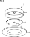
- FIG 4 illustrates a schematic exploded lower perspective view of the control element 10 according to the first embodiment of the present invention.
- the control element 10 includes the rotary knob 26, the metal plate 28 and the base plate 30.
- the base plate 30 is attachable or attached on the upper surface of the glass panel 14.
- the rotary knob 26 with the metal plate 28 is rotatable on the base plate 30.
- the first sensor element 16 is attached at the metal plate 28.
- the metal plate 28 and the first sensor element 16 form a single-piece part.
- the rotation of the rotary knob 26 with the metal plate 28 causes a movement of the first sensor element 16.
- the rotation of the rotary knob 26 changes the distance between the first sensor element 16 and the second sensor element 18.
- FIG 5 illustrates a schematic top view of the control element 10 according to the first embodiment of the present invention.
- the control element 10 includes the rotary knob 26 and the base plate 30.
- the base plate 30 is attached on the upper surface of the glass panel 14.
- the rotary knob 26 with the metal plate 28 is rotatable on the base plate 30.
- FIG 6 illustrates a schematic sectional perspective view of the control element 10 according to the first embodiment of the present invention.
- the control element 10 includes the rotary knob 26, the metal plate 28 and the base plate 30.
- the base plate 30 is attached on the upper surface of the glass panel 14.
- the first sensor element 16 is attached at the metal plate 28.
- the metal plate 28 and the first sensor element 16 form a single-piece part.
- FIG 7 illustrates a schematic exploded lower perspective view of the control element 10 according to a second embodiment of the present invention.
- the control element 10 includes the rotary knob 26 and the base plate 30.
- the base plate 30 is attachable or attached on the upper surface of the glass panel 14.
- the base plate 30 is glued on the upper surface of the glass panel 14.
- the rotary knob 26 is rotatable on the base plate 30.
- the rotary knob 26 is made of metal, conductive plastic and/or a combination of metal and plastic.
- the first sensor element 16 is directly attached at the rotary knob 26.
- the rotary knob 26 and the first sensor element 16 form a single-piece part.
- the control element 10 of the second embodiment does not require the metal plate 28.
- the rotation of the rotary knob 26 causes the movement of the first sensor element 16.
- the rotation of the rotary knob 26 changes the distance between the first sensor element 16 and the second sensor element 18.
- FIG 8 illustrates a schematic exploded upper perspective view of the control element 10 according to the second embodiment of the present invention.
- the control element 10 includes the rotary knob 26 and the base plate 30.
- the base plate 30 is attachable or attached on the upper surface of the glass panel 14.
- the first sensor element 16 is directly attached at the rotary knob 26.
- the rotary knob 26 and the first sensor element 16 form a single-piece part.
- the rotary knob 26 with the first sensor element 16 is rotatable on the base plate 30.
- the control element 10 according to the second embodiment does not include the metal plate 28 and may be realised by low complexity.
- the user interface of the present invention provides a wireless connection between the control element 10 and the printed circuit board 12 arranged at different sides of the glass panel 14.
- the wireless connection through the glass panel 14 does not require any holes in said glass panel 14.
Abstract
The present invention relates to a control element (10) for a user interface of a domestic appliance, in particular a cooking hob. The control element (10) is attachable on an upper surface or at an outer surface of a glass panel (14). The control element (10) includes a base element (30) attachable on the upper or at the outer surface, respectively, of the glass panel (14). The control element (10) includes a moveable element (26) attached at the base element (30). The control element (10) includes a sensor element (16) connected to and moveable by the moveable element (26). The sensor element (16) is wirelessly connectable or connected to at least one further sensor element (18) arranged beneath the upper or at the inner surface, respectively, of the glass panel (14). Further, the present invention relates to a user interface comprising said control element (10) and at least one printed circuit board (12) arrangeable beneath a lower surface or at an inner surface, respectively, of the glass panel (14).
Description
- The present invention relates to a control element for a user interface of a domestic appliance, in particular a cooking hob. Further, the present invention relates to a user interface of a domestic appliance, in particular a cooking hob. Moreover, the present invention relates to a domestic appliance. In particular, the present invention relates to a cooking hob.
- A conventional user interface for a cooking hob comprises control elements arranged on an upper side or at a front side of a glass panel and a printed circuit board arranged beneath or behind said glass panel, respectively. For example, the control element is a rotary knob. The connection between the control elements and the printed circuit board requires holes in the glass panel. However, the drilling of holes in the glass panel is complex and expensive. It would be advantageous, if the holes in the glass panel could be omitted.
- It is an object of the present invention to provide a control element for a user interface of a domestic appliance, which may be arranged on or at a glass panel without any holes.
- The object is achieved by the control element according to
claim 1. - According to the present invention a control element for a user interface of a domestic appliance, in particular of a cooking hob, is provided, wherein:
- the control element is attachable on an upper surface or at an outer surface of a glass panel,
- the control element includes a base element attachable on the upper or at the outer surface, respectively, of the glass panel,
- the control element includes a moveable element attached at the base element,
- the control element includes a sensor element connected to and moveable by the moveable element, and
- the sensor element is wirelessly connectable or connected to at least one further sensor element arranged beneath the upper or at the inner surface, respectively, of the glass panel.
- The control element of the present invention allows a wireless connection between said control element and a circuit arranged at the other side of the glass panel. The wireless connection through the glass panel does not require any holes in said glass panel. Neither direct electric connections nor mechanical connections are required between the control element and the circuit. For example, the sensor element of the control element and the further sensor element form a capacitive sensor.
- For example, the moveable element is a rotary knob, wherein preferably said rotary knob is made of metal, conductive plastic and/or a combination of metal and plastic. The electric conductivity of the rotary knob allows a conductive path from a touch point of the user to the surface of the glass panel.
- Further, the control element may include a metal plate arranged at or inside the moveable element, wherein the sensor element is an appendix of said metal plate.
- Alternatively, the sensor element may be directly connected to the moveable element, wherein preferably the sensor element is an appendix of the moveable element.
- Preferably, the control element and/or the moveable element are cylindrical.
- Further, the control element may include at least one induction coil for supplying electric energy, wherein preferably the control element includes at least one circuitry associated with said induction coil.
- Moreover, the control element may include at least one light source element, wherein preferably said light source element is connected to the induction coil and/or the circuitry associated with said induction coil. For example, the light source element is at least one light emitting diode (LED).
- Alternatively or additionally, the control element may include at least one vibration element, wherein preferably said light vibration element is connected to the induction coil.
- Further, the present invention relates to a user interface comprising at least one control element mentioned above, wherein the user interface comprises at least one printed circuit board arrangeable beneath a lower surface or at an inner surface, respectively, of the glass panel, wherein the printed circuit board includes at least one further sensor element wirelessly connected or connectable to the sensor element of control element.
- Preferably, the sensor element and the further sensor element form a capacitive sensor.
- Optionally, the printed circuit board includes at least one further induction coil wirelessly connectable or connected to the induction coil of the control element.
- At last, the present invention relates to a domestic appliance, in particular a cooking hob, wherein the domestic appliance comprises at least one control element and/or at least one user interface mentioned above.
- Novel and inventive features of the present invention are set forth in the appended claims.
- The present invention will be described in further detail with reference to the drawing, in which
- FIG 1
- illustrates a schematic perspective view of a user interface according to a preferred embodiment of the present invention,
- FIG 2
- illustrates a schematic perspective view of the user interface according to a further embodiment of the present invention,
- FIG 3
- illustrates a schematic exploded upper perspective view of a control element according to a first embodiment of the present invention,
- FIG 4
- illustrates a schematic exploded lower perspective view of the control element according to the first embodiment of the present invention,
- FIG 5
- illustrates a schematic top view of the control element according to the first embodiment of the present invention,
- FIG 6
- illustrates a schematic sectional perspective view of the control element according to the first embodiment of the present invention,
- FIG 7
- illustrates a schematic exploded lower perspective view of the control element according to a second embodiment of the present invention, and
- FIG 8
- illustrates a schematic exploded upper perspective view of the control element according to the second embodiment of the present invention.
-
FIG 1 illustrates a schematic perspective view of a user interface according to a preferred embodiment of the present invention. The user interface is provided for a domestic appliance, in particular for a cooking hob. - The user interface comprises at least one
control element 10 and a printedcircuit board 12. Thecontrol element 10 is arranged above aglass panel 14, while the printedcircuit board 12 is arranged beneath saidglass panel 14. In this example, theglass panel 14 is arranged horizontally and forms a part of a cooking hob. - The
control element 10 is cylindrical and attached on the upper surface of theglass panel 14. Thecontrol element 10 includes afirst sensor element 16 arranged inside saidcontrol element 10. Thefirst sensor element 16 is arranged in an outer portion within thecontrol element 10. - The printed
circuit board 12 is arranged beneath theglass panel 14. In this example, the printedcircuit board 12 is arranged horizontally and extends substantially parallel to theglass panel 14. The printedcircuit board 12 includes asecond sensor element 18. - The
control element 10 is rotatable around its axis of rotational symmetry. The user interface is manipulated by touching thecontrol element 10. Further, by rotating thecontrol element 10 the position of thefirst sensor element 16 changes. The distance between thefirst sensor element 16 and thesecond sensor element 18 varies by the rotation of thecontrol element 10. In a limit case, thefirst sensor element 16 is arranged directly above thesecond sensor element 18. - For example, the
first sensor element 16 and thesecond sensor element 18 form a capacitive sensor. - A control signal is generated in the
second sensor element 18. The signal strength of said control signal depends on the distance between thefirst sensor element 16 and thesecond sensor element 18. When thefirst sensor element 16 is arranged directly in-line with thesecond sensor element 18, then a capacitance is generated, wherein the signal strength of said capacitance is used for detecting the position of thecontrol element 10. Preferably, a plurality ofsecond sensor elements 18 is arranged in a circular path extending along the circumference of the path of thefirst sensor element 16. -
FIG 2 illustrates a schematic perspective view of the user interface according to a further embodiment of the present invention. - In the further embodiment the
control element 10 includes thefirst sensor element 16 and additionally alight source element 20 and afirst induction coil 22 with an associated circuitry, while the printedcircuit board 12 includes thesecond sensor element 18 and additionally asecond induction coil 24 with an associated circuitry. - The
first induction coil 22 and thesecond induction coil 24 provide an inductive coupling between the printedcircuit board 12 and thecontrol element 10. Said inductive coupling allows a wireless electric energy transfer from the printedcircuit board 12 to thecontrol element 10. In this example, thelight source element 20 is supplied via said inductive coupling. - Preferably, the
light source element 20 consists of one or more light emitting diodes. Thecontrol element 10 is illuminated by thelight source element 20. - Optionally, the
control element 10 includes avibration element 20 instead of or in addition to thelight source element 20. For example, thevibration element 20 is an aid for people with disabilities. -
FIG 3 illustrates a schematic exploded upper perspective view of thecontrol element 10 according to a first embodiment of the present invention. - The
control element 10 includes arotary knob 26, ametal plate 28 and abase plate 30. Thebase plate 30 is attachable or attached on the upper surface of theglass panel 14. For example, thebase plate 30 is glued on the upper surface of theglass panel 14. Therotary knob 26 is rotatable on thebase plate 30. Preferably, therotary knob 26 is made of metal, conductive plastic and/or a combination of metal and plastic. - The
metal plate 28 is attached inside therotary knob 26. Thus, themetal plate 28 is rotated synchronously with therotary knob 26. -
FIG 4 illustrates a schematic exploded lower perspective view of thecontrol element 10 according to the first embodiment of the present invention. - The
control element 10 includes therotary knob 26, themetal plate 28 and thebase plate 30. Thebase plate 30 is attachable or attached on the upper surface of theglass panel 14. Therotary knob 26 with themetal plate 28 is rotatable on thebase plate 30. - The
first sensor element 16 is attached at themetal plate 28. For example, themetal plate 28 and thefirst sensor element 16 form a single-piece part. - The rotation of the
rotary knob 26 with themetal plate 28 causes a movement of thefirst sensor element 16. Thus, the rotation of therotary knob 26 changes the distance between thefirst sensor element 16 and thesecond sensor element 18. -
FIG 5 illustrates a schematic top view of thecontrol element 10 according to the first embodiment of the present invention. - The
control element 10 includes therotary knob 26 and thebase plate 30. Thebase plate 30 is attached on the upper surface of theglass panel 14. Therotary knob 26 with themetal plate 28 is rotatable on thebase plate 30. -
FIG 6 illustrates a schematic sectional perspective view of thecontrol element 10 according to the first embodiment of the present invention. - The
control element 10 includes therotary knob 26, themetal plate 28 and thebase plate 30. Thebase plate 30 is attached on the upper surface of theglass panel 14. Thefirst sensor element 16 is attached at themetal plate 28. For example, themetal plate 28 and thefirst sensor element 16 form a single-piece part. -
FIG 7 illustrates a schematic exploded lower perspective view of thecontrol element 10 according to a second embodiment of the present invention. - The
control element 10 includes therotary knob 26 and thebase plate 30. Thebase plate 30 is attachable or attached on the upper surface of theglass panel 14. For example, thebase plate 30 is glued on the upper surface of theglass panel 14. Therotary knob 26 is rotatable on thebase plate 30. Preferably, therotary knob 26 is made of metal, conductive plastic and/or a combination of metal and plastic. - The
first sensor element 16 is directly attached at therotary knob 26. For example, therotary knob 26 and thefirst sensor element 16 form a single-piece part. Thecontrol element 10 of the second embodiment does not require themetal plate 28. - The rotation of the
rotary knob 26 causes the movement of thefirst sensor element 16. Thus, the rotation of therotary knob 26 changes the distance between thefirst sensor element 16 and thesecond sensor element 18. -
FIG 8 illustrates a schematic exploded upper perspective view of thecontrol element 10 according to the second embodiment of the present invention. - The
control element 10 includes therotary knob 26 and thebase plate 30. Thebase plate 30 is attachable or attached on the upper surface of theglass panel 14. Thefirst sensor element 16 is directly attached at therotary knob 26. For example, therotary knob 26 and thefirst sensor element 16 form a single-piece part. Therotary knob 26 with thefirst sensor element 16 is rotatable on thebase plate 30. - The
control element 10 according to the second embodiment does not include themetal plate 28 and may be realised by low complexity. - The user interface of the present invention provides a wireless connection between the
control element 10 and the printedcircuit board 12 arranged at different sides of theglass panel 14. The wireless connection through theglass panel 14 does not require any holes in saidglass panel 14. - Although illustrative embodiments of the present invention have been described herein with reference to the accompanying drawings, it is to be understood that the present invention is not limited to those precise embodiment, and that various other changes and modifications may be affected therein by one skilled in the art without departing from the scope or spirit of the invention. All such changes and modifications are intended to be included within the scope of the invention as defined by the appended claims.
-
- 10
- control element
- 12
- printed circuit board
- 14
- glass panel
- 16
- first sensor element
- 18
- second sensor element
- 20
- light source element, vibration element
- 22
- first induction coil
- 24
- second induction coil
- 26
- rotary knob
- 28
- metal plate
- 30
- base plate
Claims (12)
- A control element (10) for a user interface of a domestic appliance, in particular of a cooking hob, wherein:- the control element (10) is attachable on an upper surface or at an outer surface of a glass panel (14),- the control element (10) includes a base element (30) attachable on the upper or at the outer surface, respectively, of the glass panel (14),- the control element (10) includes a moveable element (26) attached at the base element (30),- the control element (10) includes a sensor element (16) connected to and moveable by the moveable element (26), and- the sensor element (16) is wirelessly connectable or connected to at least one further sensor element (18) arranged beneath the upper or at the inner surface, respectively, of the glass panel (14).
- The control element according to claim 1,
characterised in that
the moveable element (26) is a rotary knob (26), wherein preferably said rotary knob (26) is made of metal, conductive plastic and/or a combination of metal and plastic. - The control element according to claim 1 or 2,
characterised in that
the control element (10) includes a metal plate (28) arranged at or inside the moveable element (26), wherein the sensor element (16) is an appendix of said metal plate (28). - The control element according to claim 1 or 2,
characterised in that
the sensor element (16) is directly connected to the moveable element (26), wherein preferably the sensor element (16) is an appendix of the moveable element (26). - The control element according to any one of the preceding claims,
characterised in that
the control element (10) and/or the moveable element (26) are cylindrical. - The control element according to any one of the preceding claims,
characterised in that
the control element (10) includes at least one induction coil (22) for supplying electric energy, wherein preferably the control element (10) includes at least one circuitry associated with said induction coil (22). - The control element according to any one of the preceding claims,
characterised in that
the control element (10) includes at least one light source element (20), wherein preferably said light source element (20) is connected to the induction coil (22) and/or the circuitry associated with said induction coil (22). - The control element according to any one of the preceding claims,
characterised in that
the control element (10) includes at least one vibration element (20), wherein preferably said light vibration element (20) is connected to the induction coil (22). - A user interface comprising at least one control element (10) according to any one of the preceding claims,
characterised in that
the user interface comprises at least one printed circuit board (12) arrangeable beneath a lower surface or at an inner surface, respectively, of the glass panel (14), wherein the printed circuit board (12) includes at least one further sensor element (18) wirelessly connected or connectable to the sensor element (16) of control element (10). - The user interface according to claim 9,
characterised in that
the sensor element (16) and the further sensor element (18) form a capacitive sensor. - The user interface according to claim 9 or 10,
characterised in that
the printed circuit board (12) includes at least one further induction coil (24) wirelessly connectable or connected to the induction coil (22) of the control element (10). - A domestic appliance, in particular a cooking hob,
characterised in that
the domestic appliance comprises at least one control element (10) according to any one of the claims 1 to 8 and/or at least one user interface according to any one of the claims 9 to 11.
Priority Applications (1)
| Application Number | Priority Date | Filing Date | Title |
|---|---|---|---|
| EP19185904.0A EP3763998A1 (en) | 2019-07-12 | 2019-07-12 | Control element for a user interface of a domestic appliance |
Applications Claiming Priority (1)
| Application Number | Priority Date | Filing Date | Title |
|---|---|---|---|
| EP19185904.0A EP3763998A1 (en) | 2019-07-12 | 2019-07-12 | Control element for a user interface of a domestic appliance |
Publications (1)
| Publication Number | Publication Date |
|---|---|
| EP3763998A1 true EP3763998A1 (en) | 2021-01-13 |
Family
ID=67262106
Family Applications (1)
| Application Number | Title | Priority Date | Filing Date |
|---|---|---|---|
| EP19185904.0A Withdrawn EP3763998A1 (en) | 2019-07-12 | 2019-07-12 | Control element for a user interface of a domestic appliance |
Country Status (1)
| Country | Link |
|---|---|
| EP (1) | EP3763998A1 (en) |
Citations (9)
| Publication number | Priority date | Publication date | Assignee | Title |
|---|---|---|---|---|
| EP0797227A2 (en) * | 1996-03-20 | 1997-09-24 | E.G.O. ELEKTRO-GERÄTEBAU GmbH | Device to control electrically controlled apparatus |
| DE10218294A1 (en) * | 2002-04-24 | 2003-11-20 | Bsh Bosch Siemens Hausgeraete | Device for controlling electrically driven equipment, especially domestic devices, has operating element with light element showing machine operating state and/or operating element switch setting |
| DE102005049995A1 (en) * | 2005-10-12 | 2007-04-19 | E.G.O. Elektro-Gerätebau GmbH | Operating device for preferably electrical heating appliance has additional switching facility provided on rotary controller and provides signal transmission of switching action to control unit below face of electrical appliance |
| DE102006026187A1 (en) * | 2006-05-30 | 2007-12-06 | E.G.O. Elektro-Gerätebau GmbH | Electric appliance e.g. electrical-stove top, operating device for adjusting power and operating sequence, has two rotary components designed for rotary operation and including outer area and fixed displays |
| EP2251762A2 (en) * | 2009-05-14 | 2010-11-17 | E.G.O. Elektro-Gerätebau GmbH | Operating device for an electric device |
| EP2821709A1 (en) * | 2013-07-01 | 2015-01-07 | BSH Bosch und Siemens Hausgeräte GmbH | Operating device with an operating element with an adhesive element on the bottom of the operating element and household device with such an operating device |
| DE102013217273A1 (en) * | 2013-08-29 | 2015-03-05 | BSH Bosch und Siemens Hausgeräte GmbH | Operating device for a household appliance with a vibration unit and / or a timer unit in the control element and household appliance with such an operating device |
| DE102017201659A1 (en) * | 2017-02-02 | 2018-08-02 | BSH Hausgeräte GmbH | Operating device for a household appliance with sensor device for detecting an absolute angle of rotation of a control element and household appliance |
| DE102018200337A1 (en) * | 2018-01-11 | 2019-07-11 | BSH Hausgeräte GmbH | Operating device for a household appliance |
-
2019
- 2019-07-12 EP EP19185904.0A patent/EP3763998A1/en not_active Withdrawn
Patent Citations (9)
| Publication number | Priority date | Publication date | Assignee | Title |
|---|---|---|---|---|
| EP0797227A2 (en) * | 1996-03-20 | 1997-09-24 | E.G.O. ELEKTRO-GERÄTEBAU GmbH | Device to control electrically controlled apparatus |
| DE10218294A1 (en) * | 2002-04-24 | 2003-11-20 | Bsh Bosch Siemens Hausgeraete | Device for controlling electrically driven equipment, especially domestic devices, has operating element with light element showing machine operating state and/or operating element switch setting |
| DE102005049995A1 (en) * | 2005-10-12 | 2007-04-19 | E.G.O. Elektro-Gerätebau GmbH | Operating device for preferably electrical heating appliance has additional switching facility provided on rotary controller and provides signal transmission of switching action to control unit below face of electrical appliance |
| DE102006026187A1 (en) * | 2006-05-30 | 2007-12-06 | E.G.O. Elektro-Gerätebau GmbH | Electric appliance e.g. electrical-stove top, operating device for adjusting power and operating sequence, has two rotary components designed for rotary operation and including outer area and fixed displays |
| EP2251762A2 (en) * | 2009-05-14 | 2010-11-17 | E.G.O. Elektro-Gerätebau GmbH | Operating device for an electric device |
| EP2821709A1 (en) * | 2013-07-01 | 2015-01-07 | BSH Bosch und Siemens Hausgeräte GmbH | Operating device with an operating element with an adhesive element on the bottom of the operating element and household device with such an operating device |
| DE102013217273A1 (en) * | 2013-08-29 | 2015-03-05 | BSH Bosch und Siemens Hausgeräte GmbH | Operating device for a household appliance with a vibration unit and / or a timer unit in the control element and household appliance with such an operating device |
| DE102017201659A1 (en) * | 2017-02-02 | 2018-08-02 | BSH Hausgeräte GmbH | Operating device for a household appliance with sensor device for detecting an absolute angle of rotation of a control element and household appliance |
| DE102018200337A1 (en) * | 2018-01-11 | 2019-07-11 | BSH Hausgeräte GmbH | Operating device for a household appliance |
Similar Documents
| Publication | Publication Date | Title |
|---|---|---|
| US7642673B2 (en) | Operating device for an electrical appliance and method for operating an electrical appliance | |
| US8168908B2 (en) | Capacitive touch switch | |
| KR101665135B1 (en) | Proximity sensor and revolution operation detecting device | |
| US10050622B2 (en) | Operating device and appliance having the device | |
| US20110187204A1 (en) | Inductive touch key switch system, assembly and circuit | |
| WO2018205639A1 (en) | Multifunctional lamp | |
| EP1924000A2 (en) | Household appliance with touch-type user control devices | |
| US20160084486A1 (en) | Lighting device controllable by hover operation | |
| JP2010267616A (en) | Electronic equipment control device | |
| EP3596827B1 (en) | Capacitive sensor switch with display | |
| CN107110511B (en) | Operation of a household appliance by means of a removable operating element | |
| US11431172B2 (en) | Control system for use in controlling operation of an electrical appliance | |
| US20160116622A1 (en) | Cabinet touch control | |
| EP3218886B1 (en) | Electronic control device | |
| EP3763998A1 (en) | Control element for a user interface of a domestic appliance | |
| CN207558181U (en) | Remote controler | |
| KR102424535B1 (en) | Attachable command input apparatus and cooking device having the same | |
| US20190109592A1 (en) | Operator control device, in particular for an electronic domestic appliance and electronic domestic appliance | |
| AU2021105122A4 (en) | Portable operating device for controlling a kitchen appliance from different operating positions and kitchen appliance system | |
| CN211551694U (en) | Rotary operating system of household appliance and household appliance | |
| CN208510778U (en) | Cooking utensil | |
| CN210377202U (en) | Non-contact non-conductive knob | |
| US20180321747A1 (en) | Linear touch-sensitive switch | |
| CN209283202U (en) | Input unit and household electrical appliance | |
| KR102290744B1 (en) | The use display device for the electric range |
Legal Events
| Date | Code | Title | Description |
|---|---|---|---|
| PUAI | Public reference made under article 153(3) epc to a published international application that has entered the european phase |
Free format text: ORIGINAL CODE: 0009012 |
|
| STAA | Information on the status of an ep patent application or granted ep patent |
Free format text: STATUS: THE APPLICATION HAS BEEN PUBLISHED |
|
| AK | Designated contracting states |
Kind code of ref document: A1 Designated state(s): AL AT BE BG CH CY CZ DE DK EE ES FI FR GB GR HR HU IE IS IT LI LT LU LV MC MK MT NL NO PL PT RO RS SE SI SK SM TR |
|
| AX | Request for extension of the european patent |
Extension state: BA ME |
|
| STAA | Information on the status of an ep patent application or granted ep patent |
Free format text: STATUS: THE APPLICATION IS DEEMED TO BE WITHDRAWN |
|
| 18D | Application deemed to be withdrawn |
Effective date: 20210714 |