EP3763995A1 - Illumination lens - Google Patents
Illumination lens Download PDFInfo
- Publication number
- EP3763995A1 EP3763995A1 EP19764305.9A EP19764305A EP3763995A1 EP 3763995 A1 EP3763995 A1 EP 3763995A1 EP 19764305 A EP19764305 A EP 19764305A EP 3763995 A1 EP3763995 A1 EP 3763995A1
- Authority
- EP
- European Patent Office
- Prior art keywords
- face
- lens
- incident
- lens body
- light
- Prior art date
- Legal status (The legal status is an assumption and is not a legal conclusion. Google has not performed a legal analysis and makes no representation as to the accuracy of the status listed.)
- Granted
Links
Images




Classifications
-
- F—MECHANICAL ENGINEERING; LIGHTING; HEATING; WEAPONS; BLASTING
- F21—LIGHTING
- F21V—FUNCTIONAL FEATURES OR DETAILS OF LIGHTING DEVICES OR SYSTEMS THEREOF; STRUCTURAL COMBINATIONS OF LIGHTING DEVICES WITH OTHER ARTICLES, NOT OTHERWISE PROVIDED FOR
- F21V7/00—Reflectors for light sources
- F21V7/04—Optical design
-
- G—PHYSICS
- G02—OPTICS
- G02B—OPTICAL ELEMENTS, SYSTEMS OR APPARATUS
- G02B19/00—Condensers, e.g. light collectors or similar non-imaging optics
- G02B19/0033—Condensers, e.g. light collectors or similar non-imaging optics characterised by the use
- G02B19/0047—Condensers, e.g. light collectors or similar non-imaging optics characterised by the use for use with a light source
- G02B19/0061—Condensers, e.g. light collectors or similar non-imaging optics characterised by the use for use with a light source the light source comprising a LED
-
- B—PERFORMING OPERATIONS; TRANSPORTING
- B60—VEHICLES IN GENERAL
- B60Q—ARRANGEMENT OF SIGNALLING OR LIGHTING DEVICES, THE MOUNTING OR SUPPORTING THEREOF OR CIRCUITS THEREFOR, FOR VEHICLES IN GENERAL
- B60Q3/00—Arrangement of lighting devices for vehicle interiors; Lighting devices specially adapted for vehicle interiors
- B60Q3/20—Arrangement of lighting devices for vehicle interiors; Lighting devices specially adapted for vehicle interiors for lighting specific fittings of passenger or driving compartments; mounted on specific fittings of passenger or driving compartments
- B60Q3/233—Seats; Arm rests; Head rests
-
- B—PERFORMING OPERATIONS; TRANSPORTING
- B60—VEHICLES IN GENERAL
- B60Q—ARRANGEMENT OF SIGNALLING OR LIGHTING DEVICES, THE MOUNTING OR SUPPORTING THEREOF OR CIRCUITS THEREFOR, FOR VEHICLES IN GENERAL
- B60Q3/00—Arrangement of lighting devices for vehicle interiors; Lighting devices specially adapted for vehicle interiors
- B60Q3/40—Arrangement of lighting devices for vehicle interiors; Lighting devices specially adapted for vehicle interiors specially adapted for specific vehicle types
- B60Q3/41—Arrangement of lighting devices for vehicle interiors; Lighting devices specially adapted for vehicle interiors specially adapted for specific vehicle types for mass transit vehicles, e.g. buses
- B60Q3/44—Spotlighting, e.g. reading lamps
-
- B—PERFORMING OPERATIONS; TRANSPORTING
- B60—VEHICLES IN GENERAL
- B60Q—ARRANGEMENT OF SIGNALLING OR LIGHTING DEVICES, THE MOUNTING OR SUPPORTING THEREOF OR CIRCUITS THEREFOR, FOR VEHICLES IN GENERAL
- B60Q3/00—Arrangement of lighting devices for vehicle interiors; Lighting devices specially adapted for vehicle interiors
- B60Q3/60—Arrangement of lighting devices for vehicle interiors; Lighting devices specially adapted for vehicle interiors characterised by optical aspects
-
- F—MECHANICAL ENGINEERING; LIGHTING; HEATING; WEAPONS; BLASTING
- F21—LIGHTING
- F21V—FUNCTIONAL FEATURES OR DETAILS OF LIGHTING DEVICES OR SYSTEMS THEREOF; STRUCTURAL COMBINATIONS OF LIGHTING DEVICES WITH OTHER ARTICLES, NOT OTHERWISE PROVIDED FOR
- F21V5/00—Refractors for light sources
- F21V5/04—Refractors for light sources of lens shape
-
- F—MECHANICAL ENGINEERING; LIGHTING; HEATING; WEAPONS; BLASTING
- F21—LIGHTING
- F21V—FUNCTIONAL FEATURES OR DETAILS OF LIGHTING DEVICES OR SYSTEMS THEREOF; STRUCTURAL COMBINATIONS OF LIGHTING DEVICES WITH OTHER ARTICLES, NOT OTHERWISE PROVIDED FOR
- F21V5/00—Refractors for light sources
- F21V5/04—Refractors for light sources of lens shape
- F21V5/045—Refractors for light sources of lens shape the lens having discontinuous faces, e.g. Fresnel lenses
-
- G—PHYSICS
- G02—OPTICS
- G02B—OPTICAL ELEMENTS, SYSTEMS OR APPARATUS
- G02B19/00—Condensers, e.g. light collectors or similar non-imaging optics
- G02B19/0004—Condensers, e.g. light collectors or similar non-imaging optics characterised by the optical means employed
- G02B19/0028—Condensers, e.g. light collectors or similar non-imaging optics characterised by the optical means employed refractive and reflective surfaces, e.g. non-imaging catadioptric systems
Definitions
- the present invention relates to a lens for illumination, distributing light incident from a light source on a lens body in a predetermined direction or range, and particularly relates to a lens for illumination, constituting a reading lamp installed in a seat.
- the conventional lens for illumination that which constitutes a reading lamp, being installed in a backrest of a seat for use in a railroad vehicle, is known, for example.
- the reading lamp irradiates spot light on the hands of a passenger, and it is configured such that an LED as a light source and a lens to obtain a desired spot light distribution are housed in a spherical lamp body, respectively, the lamp body being rotatably supported in a housing to allow the irradiation direction of the spot light to be adjusted.
- Patent Document 1 refer to Patent Document 1.
- Such a lens constituting a reading lamp is generally formed in a bowl shape, the bottom apex part thereof being opposed to an LED, as shown in Figure 1 in Patent Document 1.
- the light from the LED is taken in from the incident face provided in a recessed manner in the bottom apex part thereof into the inside thereof, and is condensed with the utilization of total reflection in the entire region in the inside of the lens outer periphery, being emitted from the emission face to obtain a predetermined light distribution.
- the present invention has been made in view of the above-mentioned problems that are associated with the conventional technology, and is intended to provide a lens for illumination that can suppress uncomfortable glare with no need for adding an extra component; that can be compactly configured without bringing about an increase in size of the entire illumination device; and that also offers an improvement in mountability in a limited space therefor.
- the lens body distributes the light incident thereon from a light source in a predetermined direction or range.
- the light from the light source is efficiently taken in into the inside of the lens body from the incident face, being provided in a recessed manner in the bottom apex part of the lens body.
- the light from the light source is advanced straight or bent to be passed through the inside of the lens body in accordance with the angle with respect to the incident face.
- a part of the light, being passed through the inside of the lens body, does not reach the reflection face, being provided on the inner side of the outer periphery of the lens body, but is passed through a region further inside thereof, being emitted to the outside from the emission face, being provided at the upper end of the lens body.
- the light being not have been directed straight to the emission face, will reach the reflection face to be totally reflected to thereby be condensed toward the emission face, and then emitted from the emission face to the outside.
- the incident face distributes the light, which could be directed toward the entire region of the reflection face, only in a predetermined range within the reflection face, being adjacent to the upper end side portion, following the emission face, and being closer to the bottom apex.
- the predetermined range being located in the deeper area of the reflection face, will not come into view, so long as the viewer does not intentionally peek deep into the lens body. Therefore, within the total reflection face of the lens body, only the upper portion thereof, which will not reflect the light, will normally enter the visual field, whereby uncomfortable glare can be suppressed.
- the outer periphery of the lens body is provided with a plurality of side faces at least from the bottom apex part to a halfway point of the predetermined range, the cross section thereof having a polygonal shape.
- the incident face of the lens body is comprised of a first incident face, being provided by a bottom face formed about the optical axis of the light source, and a second incident face, being provided by a side face surrounding the first incident face.
- the light incident from the first incident face is passed through an internal region of the lens body apart from the reflection face, and emitted to the outside from the inner region, being closer to the center, within the emission face.
- the light incident from the second incident face is totally reflected in the predetermined range within the reflection face in the lens body, and emitted to the outside from the outer region around the inner region within the emission face.
- the light from the light source can be efficiently utilized.
- the lens for illumination on the outside of the outer periphery of the lens body, there is provided a mounted part for use in locating the lens body with respect to a mounting portion of a mating component of the lens body.
- the lens for illumination can be easily mounted in a lamp body of a reading lamp, or the like, being constituted thereby.
- the above-described lens for illumination is suitable as a component constituting a reading lamp, being installed in a seat, as stated in the above [5].
- a lens for illumination can be configured compactly without bringing about an increase in size of the entire illumination device; and its mountability in a limited space can be improved.
- FIGS 1 to 8 show one embodiment of the present invention.
- a lens for illumination 50 includes a lens body 51, which distributes light incident from the light source in a predetermined direction or range.
- the lens body 51 alone constitutes the lens for illumination 50, however, the lens for illumination 50 may include the lens body 51 as a part of its structure.
- the lens body 51 which is the lens for illumination 50 itself, is in the shape of a solid bowl as shown in the figure, and is integrally formed of a transparent material, such as an acrylic resin or polycarbonate.
- the lens body 51 includes an incident face 510, which is provided in a recessed manner in a bottom apex part thereof, and which receives the light from an LED 41, the LED 41 being disposed opposite to the lens body 51 on the inner side of the bottom apex part as a light source (as shown in Figure 1 ); a reflection face 520, which is provided on the inner side of the outer periphery, totally reflecting the light, having reached from the incident face 510; and an emission face 530, which is provided at the upper end of the lens body 51, being opposed to the incident face 510 and emits the light, having reached from the reflection face 520, to the outside.
- the incident face 510 being located in the bottom apex part formed in a bowl shape, is comprised of a first incident face 511, providing a bottom face formed about the optical axis of the LED 41, and a second incident face 512, providing a side face surrounding the first incident face 511.
- the first incident face 511 is formed concentrically with the LED 41 about the optical axis L thereof, being provided with an arcuate section convexed toward the LED 41.
- the light from the LED 41 is advanced straight or bent in the lens body 51 to be passed through an internal region of the lens body 51 apart from the reflection face 520, and directed toward the inner region 531, being closer to the center, within the emission face 530.
- the second incident face 512 is disposed such that it surrounds the emitting side of the LED 41, being formed into a tapered section, thereby the diameter of the opening of the recessed part in the bottom apex part being made slightly larger than that of the outer periphery of the first incident face 511.
- the second incident face 512 could be formed so as to refract the light from the LED 41 toward the entire region of the reflection face 520, but, it is formed so as to distribute such light only in a later-described predetermined range 521 within the reflection face 520, being adjacent to the upper end side portion (the upper portion 522), following the emission face 530, and being closer to the bottom apex part.
- Such light distribution control is previously established by setting the tapered angle of the second incident face 512.
- the reflection face 520 is provided as a critical angle reflection face with which the inner side of the outer periphery of the lens body 51 can totally reflect the light incident from the second incident face 512 toward the outer region 532, being closer to the outside, within the emission face 530.
- the light incident from the second incident face 512 will not reach the entire area of the reflection face 520, but will limitedly reach the predetermined range 521, being closer to the bottom apex part, within the reflection face 520.
- the predetermined range 521 corresponds to a part of the reflection face 520 the level of which ranges from the bottom apex part to, for example, two thirds of the overall height of the lens body 51.
- the reflection face 520 provides a series of slanted curved surfaces, however, by making a specific design of the curved geometry and the inclination angle of the predetermined range 521, the light, having been totally reflected, can be caused to be irradiated from the emission face 530 in a desired direction or with a desired light distribution characteristic.
- the predetermined range 521 of the reflection face 520 is provided as a series of slanted curved surfaces, causing the reflected light to be condensed in a direction approximately in parallel with the optical axis L of the LED 41.
- the predetermined range 521 and the upper portion 522 located thereabove of the reflection face 520 are shown with a symbol being given on the right or left side alone, however, it should be noted that the portion to which the symbol refers extends over the entire periphery to the opposite side (the left or right side in the figure) where no symbol is given.
- the emission face 530 is formed concentrically with the LED 41 about the optical axis L thereof, being provided with a curved section slightly bulged toward the outside, however, the emission face 530 may be formed in a flat surface.
- the emission face 530 is divided into two regions, i.e., the inner region 531, which is closer to the center, and the outer region 532 therearound, however, such division is not provided visibly.
- the inner region 531 provides a region where the light which has been made incident from the first incident face 511 is emitted directly to the outside.
- the outer region 532 provides a region where the light which has been made incident from the second incident face 512 and totally reflected in the predetermined range 521 of the reflection face 520 is emitted to the outside.
- the lens for illumination 50 is disposed ahead of the LED 41 through the holder 53.
- the holder 53 is a member to hold the lens for illumination 50, being in a cylindrical shape on the whole and provided with a flange 54 around the opening at the rear end, and is integrally formed of a synthetic resin, such as a plastic material, by using a mold.
- the holder 53 is located with a later-described LED substrate 40 by means of a locating means. More specifically, as shown in Figure 16 and Figure 17 , the flange 54 of the holder 53 is provided with a hole part 55, into which a projection 27 of a base 20 is fitted.
- a shoulder part (mounted part) 52 to be located on the edge (mounting part) of the opening at the front end of the holder 53.
- the lower portion thereof which is located closer to the bottom apex part than the shoulder part 52, provides the predetermined range 521. Strictly speaking, even the reflection face 520 is not capable of maintaining the total reflection in a portion thereof in which the shoulder part 52 is provided.
- the upper portion thereof, including the shoulder part 52, is fitted to the front of the inner periphery of the opening part 31 of a later-described cover 30, with the top face of the shoulder part 52 being engaged with a shoulder part 32, which is provided on the the inner periphery of the opening part 31.
- the lens body 51 is held between the holder 53 and the opening part 31.
- the lens body 51 is not contact with the holder 53 and the cover 30, except for the shoulder part 52 and the outer periphery, being located thereabove.
- the lens for illumination 50 and the holder 53 can be provided with means for mutually regulating the assembling orientation, 52a and 56. More specifically, as shown in Figure 16 , a notch 52a is provided for the lens for illumination 50 in one place in the shoulder part 52. On the other hand, at the opening end of the holder 53, a projection 56, which is matched to the notch 52a, is provided in one place to assure the proper orientation of the notch 52a in assembling.
- the lens body 51 has the same sectional shape over the entire periphery except for the shoulder part 52, and thus the orientation thereof is not particularly specified, however, for a later-described lens for illumination 50A, the notch 52a allows the orientation of the lens for illumination 50A to be easily determined, whereby assembling in an improper orientation can be prevented.
- Figure 9 to Figure 15 show a lens for illumination 50A according to a modification, which, although the basic geometry and size thereof are common to those of the above-described lens for illumination 50, is provided with a reflection face 520A, being different from that of the reflection face 520. Note that the same potions as those of the lens for illumination 50 are provided with the same numerals, respectively, and repeated explanation thereof will be omitted here.
- the lens for illumination 50A according to the present modification is also disposed ahead of the LED 41 through the same holder 53, being held in the lamp body 11.
- the area at least from the bottom apex part to a halfway point of the predetermined range 521 is provided with a plurality of side faces 523, with which the cross section orthogonal to the axis thereof has a polygonal shape. Then, the light, being totally reflected by the reflection face 520A, which is provided on the inner side of each side face 523, is emitted from the emission face 530 in an irradiation range having an outline of the polygonal shape.
- the outer periphery of the lens body 51A is formed such that it has four side faces 523, being inclined at an equal angle from the bottom apex part.
- reflection face 520A which is provided on the inner side of each side face 523, the light, having reached from the second incident face 512 of the incident face 510, can be condensed into a quadrangle (square), whereby the light distribution from the emission face 530 can be performed for a quadrangle (square).
- the lens for illumination 50A is configured to have four side faces 523, being inclined at an equal angle from the bottom apex part within the outer periphery thereof toward four directions, however, the specific configuration of the lens for illumination 50A is not limited to that of the lens for illumination 50A according to the present modification, and the cross section of the lens body 51 may be specified to have a triangular shape or a five- or more-sided polygonal shape, for example.
- the reading lamp 10 including the above-described lens for illumination 50, 50A as a component, will be explained.
- the reading lamp 10 according to the present embodiment provides a lighting fixture, which includes a lamp body 11, having a lens for illumination 50, 50A and a light source, the lamp body 11 being mounted to a seat 1 through a bracket 60.
- the reading lamp 10 which has been provided for the seat 1 in a railroad vehicle, will be explained, being used as an example.
- the lamp body 11, constituting a critical part of the reading lamp 10 is provided by assembling the base 20, with which the light source is disposed on the front side, with the cover 30, which surrounds the light source on the front side of the base 20, except for the irradiation range.
- the lamp body 11 is provided with a leg part, which is protruded on the side opposite to the emitting side of the light source, the tip thereof being engaged with a receiving part 65, being provided for a later-described bracket 60 (see Figure 29 ).
- the lamp body 11 is supported by the bracket 60 such that the irradiation direction of the light source (the angle of the optical axis) can be adjusted with the tip of the leg part 22 being used as a fulcrum.
- the base 20 has a disk-like shape on the whole, being integrally formed of a metal, such as an aluminum alloy by using such a method as die casting.
- the base 20 is made of a metal, being excellent in thermal conductivity, thereby serving also as a heat sink for dissipating the heat of the light source. More specifically, the base 20 has a disk-like shape on the front side, providing a mounting face 21, while being opened on the back side to have a shallow-bottom dish-like shape, the leg part 22 being provided at the center on the back side of the mounting face 21.
- the leg part 22 is formed in a shaft-like shape with the tip thereof having a semispherical shape, being protruded toward the back side perpendicularly with respect to the mounting face.
- the tip of the leg part 22 is protruded toward the outside from the end edge of the peripheral wall 23 surrounding a space on the back side of the mounting face 21 (from the reference surface on the back side of the base 20) by an amount equal to the height of the peripheral wall 23 when viewed from the side.
- the end edge of the peripheral wall 23 is provided with a flange 24, being extended sidewise.
- a rib 25 being extended four directions from the leg part 22 as the center and joined to the inner side of the peripheral wall 23.
- Each rib 25 serves not only to reinforce the leg part 22 and the peripheral wall 23, but also to function as a heat dissipation fin.
- the peripheral wall 23 and the flange 24 are notched for use as a mounting space where related components, such as a power circuit board and a light source control circuit board, are disposed.
- a locating pin 24a being protruded sidewise.
- the base 20 is provided with a later-described engaged part 26, which is used for snap-fit engagement with the cover 30.
- the engaged part 26 is disposed along the outer periphery edge of the flange 24 in each location where the rib 25 is joined thereto.
- four engaged parts 26 are provided in correspondence to the four ribs 25. More specifically, as shown in Figure 25 , on the outer periphery edge of the flange 24, the engaged part 26 is provided as an engaged groove, which is matched to the tip of an engaging claw of a later-described engaging part 34 of the cover 30.
- the cover 30 is in a semispherical bowl-shape on the whole, being integrally formed of a synthetic resin, such as a plastic material, by using a mold.
- the cover 30 is formed of a synthetic resin, which is elastically deformable, and thus the later-described engaging part 34 can be elastically deformed.
- an opening part 31 for irradiation, matching to the irradiation range of the light source, is provided, being protruded in a cylinder-like manner.
- a shoulder part 32 As shown in Figure 25 , in the inner periphery of the opening part 31, there is formed a shoulder part 32, with which the diameter of the inner periphery is contracted toward the tip.
- the cover 30 is assembled to the base 20 so as to cover the front side thereof. More specifically, an opening edge 33, which is the outermost periphery of the cover 30, is assembled to the base 20 so as to be fitted to the outer periphery edge of the flange 24, and they are fixed to each other by snap-fit engaging the engaging part 34, being provided for the cover 30, with the engaged part 26, being provided for the base 20. Therefore, the inside diameter of the opening edge 33 of the cover 30 is designed to be that which is tightly matched to the outside diameter of the flange 24 of the base 20.
- the cover 30 is provided with the engaging part 34, which is to be snap-fit engaged with the base 20.
- the engaging part 34 is to be snap-fit engaged with the base 20.
- the engaging part 34 is provided along the opening edge 33 as an engaging claw, being fitted to the engaged groove, which is the engaged part 26.
- the engaging claw which is the engaging part 34
- the engaging claw is formed such that the tip end of the claw is protruded toward the inside of the opening edge 33.
- the back of the tip end is formed in a tapered shape such that it can elastically get on the engaged groove, which is the engaged part 26.
- a pair of slits are notched such that a part of the outer periphery including the engaging part 34 can be elastically deformed toward the outside.
- the light source which is disposed on the front side of the base 20 in the lamp body 11, will be explained.
- the light source is constituted by a single LED 41, which is a semiconductor light-emitting element, being mounted on an LED substrate 40.
- the LED substrate 40 is formed in a square having a size allowing it to be accommodated within the area of the mounting face 21 of the base 20.
- an LED chip of surface-mounting type is suitable, for example. Since the LED chip of such type is well known, the detailed explanation thereof will be omitted here. Simply put, it emits light within a predetermined angle of irradiation range about the optical axis thereof perpendicular to the LED substrate 40.
- the luminescent color can be arbitrarily selected to suit to the application and type of the lighting fixture, however, for the reading lamp, white color is suitable.
- the LED 41 is required to be held in a predetermined location on the front side of the base 20 in the lamp body 11. Then, on the mounting face 21 of the base 20, there is provided a locating means for locating the LED substrate 40 when disposing it. More specifically, as shown in Figure 17 , on the mounting face 21, three projections 27 are provided. On the other hand, in the peripheral area of the LED substrate 40, there are provided hole parts 42, into which the projections 27 are fitted, respectively. In the base 20, an insertion hole 28 for inserting a wiring to supply power to the LED substrate 40 from the outside power supply is also provided (see Figure 17 ).
- a packing 43 in a ring shape is interposed, and the mounting face 21 of the base 20 and the LED substrate 40 are tightly contacted with each other through the packing 43.
- the packing 43 is integrally formed of an elastic material, such as a non-conductive silicone rubber.
- the packing 43 is a member for protecting the circuit on the LED substrate 41 as a cushioning material, and for improving the dissipation performance by enhancing the adhesion between the base 20 and the LED substrate 40.
- the lamp body 11, which provides a critical part of the above-described reading lamp 10, is mounted to the seat 1 through the bracket 60.
- the seat 1 is, for example, a two-occupant seat for use in a railroad vehicle, with which seat parts 2 and backrests 3 for two persons are arranged side by side in a line, as shown in Figure 34 , and of both side parts on the upper end side of the respective backrests 3, on the side part, being located on the outer side of the seat, the reading lamp 10 is provided.
- the reading lamp 10 is mounted to a frame in the inside of the backrest 3, the opening part 31 thereof and the surrounding portion thereof being exposed to the outside of the cover of the backrest 3.
- the bracket 60 displaceably holds the lamp body 11, having a housing part 61 for accommodating the lamp body 11 on the inner side thereof, and mounting parts 66 and 67 for fixing it to the frame in the inside of the backrest 3.
- the housing part 61 is approximately in a cylindrical shape, surrounding the entire lamp body 11, except for the opening part 31, which provides the irradiation face of the lamp body 11, and is formed of such a material as a metal.
- the housing part 61 is comprised of an outer periphery wall 62, being approximately in a cylindrical shape, a front wall 63, covering the front-side opening of the outer periphery wall 62, and a back wall 64, walling up the back-face side opening of the outer periphery wall 62.
- the inside diameter of the outer periphery wall 62 is set at a size that allows the lamp body 11 to be accommodated so as to be displaceable.
- the front wall 63 is formed such that the outer periphery of the cover 30 is slidably butted against the inner side, and is provided with a guide opening 63a, into which the opening part 31 is movably inserted.
- the guide opening 63a is extended in a vertical direction, the inside diameter and the lateral width of the guide opening 63a at the upper and lower ends thereof being designed to be slightly larger than the outside diameter of the opening part 31.
- the peripheral edge of the guide opening 63a may be provided as another part made of a synthetic resin rather than a metal.
- the inner side of the peripheral edge of the guide opening 63a may be provided with a holding member made of such a material as moquette, which is to be elastically butted against the outer periphery of the cover 30.
- the back wall 64 walls up the back side of the base 20 of the lamp body 11, however, it is not formed in the shape of a disk on the whole, but is configured such that a plurality of supporting plates are radially extended from the central portion.
- a receiving part 65 In the central portion of this back wall 64, there is provided a receiving part 65, with which the tip of the leg part 22, being provided on the back side of the base 20, is engaged.
- the receiving part 65 is formed by fitting a gromet made of a resin into a round hole produced in the central portion of the back wall 64.
- the configuration of the receiving part 65 is not limited to this, and any other configuration may be provided, so long as it allows the tip of the leg part 22 to be used as a fulcrum, being engaged therewith.
- the orientation of the opening part 31 can be changed in a variety of directions, such as the vertical, horizontal, and oblique ones, with the use of the tip of the leg part 22 as a turning center, however, in the present embodiment, the opening part 31 is guided within the guide opening 63a, being extended in a vertical direction. Therefore, the displacement of the lamp body 11 is restricted to rocking in a vertical direction with the tip of the leg part 22 being used as a turning center, whereby the irradiation direction of the LED 41 can be adjusted vertically.
- the outer periphery of the cover 30 of the lamp body 11 is slidably butted against the inner side of the front wall 63, and in addition, the outer periphery of the entire lamp body 11 is surrounded by the outer periphery wall 62, further, the tip of the leg part 22, being protruded from the base 20 of the lamp body 11, being engaged with the receiving part 65 of the back wall 64.
- the lamp body 11 is supported between the front wall 63 and the back wall 64 of the bracket 60 so as to be displaceable with the tip of the leg part 22 being used as a fulcrum, the position thereof being held by the friction force, which is given in the supported state.
- the locating pin 24a in the base 20 is also guided by an elongated hole 66a, being provided for a later-described mounting part 66 (see Figure 26 ).
- the guidance of the locating pin 24a by the elongated hole 66a is not always needed, the locating pin 24a and the elongated hole 66a mainly playing a role as components allowing the top and bottom portions of the lamp body 11 to be easily identified.
- the mounting parts 66 and 67 of the bracket 60 are to be fixed to the frame inside of the backrest 3, being configured as components separate from the housing part 61 and retrofitted thereto.
- the mounting parts 66 and 67 are formed of a metallic material, being worked to a variety of sizes and shapes in accordance with the location and shape of the frame, to which they are mounted in the inside of the backrest 3.
- the number of mounting parts 66 and 67 is not limited to two.
- an eaves part 68 is provided on the side of the front wall 63 in the housing part 61. This eaves part 68 is a portion for concealing a gap that may be produced in the mounting place, depending upon the geometry of the surface of the backrest 3, in which the reading lamp 10 is disposed.
- the lens body 51 distributes the light incident from the LED 41 in a predetermined direction or range.
- the light from the LED 41 is efficiently taken in into the inside of the lens body 51 from the incident face 510, being provided in a recessed manner in the bottom apex part of the lens body 51.
- the light from the LED 41 is advanced straight or bent to be passed through the inside of the lens body 51 in accordance with the angle with respect to the incident face 510.
- the incident face 510 is comprised of a first incident face 511, providing a bottom face of the recessed part, and a second incident face 512, providing a side face of the recessed part, both incident faces being different from each other in the light distribution characteristics.
- the light incident from the first incident face 511 is advanced straight or bent so as to be passed through an internal region of the lens body 51 apart from the reflection face 520, and emitted to the outside from the inner region 531 of the emission face 530.
- the light incident from the second incident face 512 is advanced straight or bent toward the predetermined range 521, being closer to the bottom apex part, within the reflection face 520 in the lens body 51. Then, the light, which has been totally reflected in the predetermined range 521 of the reflection face 520, is condensed in a direction approximately in parallel with the optical axis L of the LED 41, being emitted to the outside from the outer region 532 of the emission face 530.
- the second incident face 512 refracts the light from the LED 41 toward the reflection face 520, however, it will not refract the light toward the entire area of the reflection face 520, but will distribute the light only in the predetermined range 521, which is closer to the bottom apex part.
- the predetermined range 521 which is closer to the bottom apex part.
- the outer periphery of the lens body 51A has four side faces 523, which are inclined at an equal angle in four directions from the bottom apex part thereof.
- reflection face 520A which is provided on the inner side of each side face 523, the light, having reached from the second incident face 512 of the incident face 510, can be condensed into a quadrangle (square), whereby the light distribution from the emission face 530 can be performed for a quadrangle (square).
- the leg part 22 is protruded, the tip of this leg part 22 being engaged with the receiving part 65 in the housing part 61.
- the lamp body 11 can be rocked in the housing part 61 with the use of the tip of the leg part 22 as a fulcrum, whereby the irradiation direction of the LED 41can be adjusted. With such a lamp body 11, the entire shape need not be a sphere as with the conventional technology.
- the shape may be basically a disk-like simple one, allowing the LED 41 to be disposed on the front side thereof, with only the leg part 22 being locally protruded from the reference surface on the back side thereof. Accordingly, the shape of the lamp body 11 can be made non-bulky and compact, and the bracket 60, supporting the lamp body 11, can also be downsized. With the cover 30, being assembled with the front side of the base 20, the inside space of the lamp body 11 is secured.
- the front wall 63 of the bracket 60 is formed such that the outer periphery of the cover 30 is slidably butted against the inner side thereof, whereby the cover 30, which provides the front side of the lamp body 11, can be positively held.
- the opening part 31 for irradiation is cylindrically protruded, being inserted into the guide opening 63a in the front wall 63, whereby it can be rocked in a vertical direction.
- the rocking of the lamp body 11 is restricted to that in a vertical direction, using the tip of the leg part 22 as a turning center, and thus the irradiation direction of the LED 41 can be adjusted only in a vertical direction.
- the opening part 31 of the lamp body 11 is protruded to the outside from the guide opening 63a of the front wall 63, this opening part 31 serving as an operation part for moving the lamp body 11 by hand.
- the tip of the leg part 22, which provides the inclination center of the base 20 also provides the turning center of the optical axis of the LED 41 as it is, and thus adjustment of the irradiation direction of the LED 41 can be carried out while recognizing it with intuition.
- the base 20 is integrally formed of a metal, also serving as a heat sink.
- a metal also serving as a heat sink.
- the LED 41 which is disposed at the center of the front side of the base 20, and the leg part 22, which plays especially as a role of a heat dissipation fin on the back side of the base 20, are matched with each other in location on the front and back sides of the base 20, and yet around the leg part 22, a plurality of ribs 25 are radially provided, whereby the heat dissipation can be further enhanced.
- the LED substrate 40 is first disposed on the mounting face 21 of the base 20 as shown in Figure 16 and Figure 17 .
- the mounting face 21 is provided with projections 27 as a locating means.
- the LED 41 on the LED substrate 40 can be easily located.
- a packing 43 is interposed between the mounting face 21 of the base 20 and the LED substrate 40.
- the holder 53 holding the lens for illumination 50, is disposed on the LED substrate 40 in such a way that the former is superposed on the latter. Since the holder 53 is also provided with hole parts 55, into which the respective projection 27 are to be fitted, the holder 53 and the lens for illumination 50 can also be easily located. At this time, there is no need for the holder 53 being bonded onto the LED substrate 40 or the lens for illumination 50 being bonded to the holder 53.
- the cover 30 is assembled to the base 20 in such a way that the latter is covered with the former from above the holder 53 of the lens for illumination 50.
- the opening edge 33 of the cover 30 is matched to the outer periphery edge of the flange 24 of the base 20, the engaging parts 34 on the cover 30 being snap-fit engaged with the engaged parts 26 on the base 20, thereby they being fixed to each other. Therefore, in assembling the lamp body 11, there is no need for using a fixing means such as an adhesive of a screw, and the assembly thereof can be made easily by simply utilizing the respective structures of the base 20 and the cover 30.
- the snap-fit engaging will be completed in due course in association with such operation with no need for making an extra operation, such as separately deforming the engaging part 34 with the use of a tool, or the like.
- the lens for illumination 50 in the holder 53 the portion above the shoulder part 52 of the outer periphery thereof is fitted to the inner periphery of the opening part 31 of the cover 30, with the top face of the shoulder part 52 being engaged with the stepped face of the shoulder part 32 of the inner periphery of the opening part 31.
- the lens body 51 is held between the holder 53 and the opening part 31.
- the lens for illumination 50 and the holder 53 are held in place, being engaged with each other.
- the component parts provided in the inside thereof can be fixed in the respective proper locations with a pressing force, being generated as a result of engaging with each other.
- the emission face 530 of the lens for illumination 50 is matched to the opening part 31 to block it, and thus there is no need for separately preparing such a part as a transparent protection cover to cover the opening part 31.
- the lamp body 11, which has been thus assembled, is accommodated in the housing part 61 of the bracket 60 as described above for completion of a reading lamp 10.
- the lamp body 11 is handled as one unit of the reading lamp 10, together with the bracket 60.
- the reading lamp 10 is fixed to the frame in the backrest 3 of the seat 1 through the mounting parts 66 and 67 of the bracket 60 to thereby be offered to use by a seated person.
- the LED 41 which is the light source
- a finger is hooked on the opening part 31, being protruded to the outside of the housing part 61, to press it with an operating force exceeding the above-mentioned friction force, which holds the lamp body 11 in a stationary state.
- the lamp body 11 is rocked in a vertical direction with the tip of the leg part 22 of the base 20 being used as the turning center, and thus by leaving the hand from the opening part 31 at the point of time when it has been rocked to the desired irradiation direction, the lamp body 11 can be stopped in the relevant position.
- the embodiment of the present invention has been described with reference to the drawings, however, the specific configuration is not limited to that of the embodiment as described above, and various changes and modifications may be included in the present invention, so long as they do not depart from the spirit and scope thereof.
- the lenses for illumination 50 and 50A not only the entire geometry, but also the incident face 510, the reflection faces 520 and 520A and the predetermined range 521 thereof, and the specific geometry and configuration of the emission face 530 are not limited to those shown, but can be altered as appropriate.
- the lenses for illumination 50 and 50A can be utilized as an optical part for various lighting devices other than the reading lamp 10.
- the seat 1, being provided with a reading lamp 10, including a lens for illumination 50 or 50A is not limited to that for use in a railroad vehicle, and may be a seat to be installed in an airplane, a ship, or the like.
- the reading lamp 10 may be provided in such a place as the ceiling or the side wall such that it illuminates the seat 1.
- the specific geometry of a component constituting the reading lamp 10, such as the lamp body 11 or the bracket 60, is not limited to that illustrated.
- those which have various configurations other than illustrated may be adopted.
- the adjustability of the irradiation direction of the light source is not limited to the vertical direction, and may be adapted such that it is the horizontal direction or any specific angular direction as required.
- the cover 30 is provided with the engaging part 34, while the base 20 being provided with the engaged part 26, however, as an inverted aspect of the present embodiment, it may be configured such that the cover 30 is provided with the engaged part 26, while the base 20 being provided with the engaging part 34.
- the engaging part 34 is not limited to a claw-like one, and the engaged part 26 is not limited to a groove-like one into which the above-mentioned claw is fitted.
- the lens for illumination of the present invention is widely applicable also to various illuminators other than the reading lamp as an optical part thereof.
- Reference numeral 50, 50A denotes a lens; 51, 51A a lens body; 510 an incident face; 511 a first incident face; 512 a second incident face; 520, 520A a reflection face; 521 a predetermined range; 522 an upper portion; 523 a side face; 530 an emission face; 531 an inner region; 532 an outer region; 52 a shoulder part; 53 a holder; 1 a seat; 2 a seat part; 3 a backrest; 10 a reading lamp; 11 a lamp body; 20 a base; 21 a mounting face; 22 a leg part; 26 an engaged part; 30 a cover; 31 an opening part; 32 a shoulder part; 33 an opening edge; 34 an engaging part; 40 an LED substrate; 41 an LED; 60 a bracket; 61 a housing part; 62 an outer periphery wall; 63 a front wall; 64 a back wall; and 65 a receiving part; and 66, 67 a mounting part.
Landscapes
- Engineering & Computer Science (AREA)
- Physics & Mathematics (AREA)
- General Engineering & Computer Science (AREA)
- Mechanical Engineering (AREA)
- General Physics & Mathematics (AREA)
- Optics & Photonics (AREA)
- Non-Portable Lighting Devices Or Systems Thereof (AREA)
- Arrangements Of Lighting Devices For Vehicle Interiors, Mounting And Supporting Thereof, Circuits Therefore (AREA)
Abstract
Description
- The present invention relates to a lens for illumination, distributing light incident from a light source on a lens body in a predetermined direction or range, and particularly relates to a lens for illumination, constituting a reading lamp installed in a seat.
- As the conventional lens for illumination, that which constitutes a reading lamp, being installed in a backrest of a seat for use in a railroad vehicle, is known, for example. Generally, the reading lamp irradiates spot light on the hands of a passenger, and it is configured such that an LED as a light source and a lens to obtain a desired spot light distribution are housed in a spherical lamp body, respectively, the lamp body being rotatably supported in a housing to allow the irradiation direction of the spot light to be adjusted. For example, refer to
Patent Document 1. - Such a lens constituting a reading lamp is generally formed in a bowl shape, the bottom apex part thereof being opposed to an LED, as shown in
Figure 1 inPatent Document 1. With such a lens, the light from the LED is taken in from the incident face provided in a recessed manner in the bottom apex part thereof into the inside thereof, and is condensed with the utilization of total reflection in the entire region in the inside of the lens outer periphery, being emitted from the emission face to obtain a predetermined light distribution. - However, needless to say the case when the passenger looks the reading lamp right in front of the lens, even in the case when the passenger looks it from an oblique direction crossing the central axis of the lens, the total reflection face, which is provided inside of the outer periphery of the lens, can be seen, thereby the passenger feeling uncomfortable glare, which has presented a problem.
- Then, as a technology for reducing such uncomfortable glare in a lighting fixture designed on the assumption of use of a single lens of this type, there has already been proposed a lighting fixture technology with which a cylindrical hood is provided in front of the emission face of the lens, with glare-suppressing protrusions being formed in parallel on the inner circumferential surface of the hood. For example, refer to
Patent Document 2. In other words, this technology provides such a degree of depth with which the passenger is prevented from looking at the total reflection face inside of the lens through the irradiation opening located at the hood front end, and also suppresses the reflection toward the front that would be caused on the inner circumferential surface of the hood. -
- Patent Document 1: Japanese Unexamined Patent Application Publication No.
2005-129354 - Patent Document 2: Japanese Unexamined Patent Application Publication No.
2017-152320 - However, with the conventional technology as disclosed in the above-described
Patent Document 2, there have been problems that the addition of a hood to the lens increases the number of parts and thus the number of man-hours for mounting them, thereby an increase in cost being caused. In addition, upsizing of the entire reading lamp has required a larger space for installing it, and there has also arisen a problem with its mountability in a limited space in a seat backrest. - The present invention has been made in view of the above-mentioned problems that are associated with the conventional technology, and is intended to provide a lens for illumination that can suppress uncomfortable glare with no need for adding an extra component; that can be compactly configured without bringing about an increase in size of the entire illumination device; and that also offers an improvement in mountability in a limited space therefor.
- The subject matter of the present invention to achieve the above purpose is disclosed in the inventions as stated in the following respective items [1] to [5]:
- [1] A lens for illumination, distributing light incident on a lens body from a light source in a predetermined direction or range, including:
- an incident face, being provided in a recessed manner in a bottom apex part of the lens body, and receiving light from the light source, being disposed on the inner side thereof; a reflection face on the inner side of an outer periphery of the lens body, totally reflecting the light, having reached from the incident face; and an emission face at the upper end of the lens body, emitting the light, having reached from the incident face and the reflection face, to the outside,
- the incident face being formed so as to distribute the light, which could be directed toward the entire region of the reflection face, only in a predetermined range within the reflection face, being adjacent to the upper end side portion, following the emission face, and being closer to the bottom apex part.
- [2] The lens for illumination according to [1], wherein the outer periphery of the lens body is provided with a plurality of side faces at least from the bottom apex part to a halfway point of the predetermined range, the cross section orthogonal to the axis thereof having a polygonal shape, and the light, being totally reflected by the reflection face on the inner side of each side face, is emitted from the emission face in an irradiation range having an outline of the polygonal shape.
- [3] The lens for illumination according to [1] or [2], wherein the incident face is comprised of a first incident face, being provided by a bottom face formed about the optical axis of the light source, and a second incident face, being provided by a side face surrounding the first incident face,
the light incident from the first incident face being passed through an internal region of the lens body apart from the reflection face, and emitted to the outside from the inner region, being closer to the center within the emission face, and
the light incident from the second incident face being totally reflected in the predetermined range within the reflection face, and emitted to the outside from the outer region around the inner region within the emission face. - [4] The lens for illumination according to any one of [1] to [3], wherein, on the outside of the outer periphery of the lens body, there is provided a mounted part for use in locating the lens body with respect to a mounting portion of a mating component of the lens body.
- [5] The lens for illumination according to any one of [1] to [4], wherein the lens body constitutes a reading lamp, being mounted on the seat.
- Next, the functions based on the aspects of the inventions that are stated in the above items [1] to [5] will be explained. According to the lens for illumination as stated in the above item [1], the lens body distributes the light incident thereon from a light source in a predetermined direction or range. The light from the light source is efficiently taken in into the inside of the lens body from the incident face, being provided in a recessed manner in the bottom apex part of the lens body. Herein, the light from the light source is advanced straight or bent to be passed through the inside of the lens body in accordance with the angle with respect to the incident face.
- A part of the light, being passed through the inside of the lens body, does not reach the reflection face, being provided on the inner side of the outer periphery of the lens body, but is passed through a region further inside thereof, being emitted to the outside from the emission face, being provided at the upper end of the lens body. In addition, the light, being not have been directed straight to the emission face, will reach the reflection face to be totally reflected to thereby be condensed toward the emission face, and then emitted from the emission face to the outside.
- With such a way of light distribution by the lens body, the incident face distributes the light, which could be directed toward the entire region of the reflection face, only in a predetermined range within the reflection face, being adjacent to the upper end side portion, following the emission face, and being closer to the bottom apex. Thereby, even if the viewer obliquely views the emission face of the lens body, the predetermined range, being located in the deeper area of the reflection face, will not come into view, so long as the viewer does not intentionally peek deep into the lens body. Therefore, within the total reflection face of the lens body, only the upper portion thereof, which will not reflect the light, will normally enter the visual field, whereby uncomfortable glare can be suppressed.
- According to the lens for illumination as stated in the above item [2], the outer periphery of the lens body is provided with a plurality of side faces at least from the bottom apex part to a halfway point of the predetermined range, the cross section thereof having a polygonal shape. The light, being totally reflected by the reflection face, being provided on the inner side of each of the plurality of side faces, is emitted from the emission face in an irradiation range having an outline of the polygonal shape. With such a lens body, by giving, for example, a cross-sectional shape of quadrangle for the area from the bottom apex part to a halfway point of the predetermined range, distribution control to provide an illumination range of a quadrangle can be executed.
- According to the lens for illumination as stated in the above item [3], the incident face of the lens body is comprised of a first incident face, being provided by a bottom face formed about the optical axis of the light source, and a second incident face, being provided by a side face surrounding the first incident face. The light incident from the first incident face is passed through an internal region of the lens body apart from the reflection face, and emitted to the outside from the inner region, being closer to the center, within the emission face.
- In addition, the light incident from the second incident face is totally reflected in the predetermined range within the reflection face in the lens body, and emitted to the outside from the outer region around the inner region within the emission face. With such a lens body, the light from the light source can be efficiently utilized.
- According to the lens for illumination as stated in the above item [4], on the outside of the outer periphery of the lens body, there is provided a mounted part for use in locating the lens body with respect to a mounting portion of a mating component of the lens body. Thereby, the lens for illumination can be easily mounted in a lamp body of a reading lamp, or the like, being constituted thereby.
- The above-described lens for illumination is suitable as a component constituting a reading lamp, being installed in a seat, as stated in the above [5].
- With the lens for illumination according to the present invention, uncomfortable glare can be suppressed with no need for adding an extra component; a lens for illumination can be configured compactly without bringing about an increase in size of the entire illumination device; and its mountability in a limited space can be improved.
-
-
Figure 1 is a sectional view showing light distribution control of a lens for illumination in a lamp body of a reading lamp according to an embodiment of the present invention; -
Figure 2 is a perspective view showing a lens for illumination according to an embodiment of the present invention; -
Figure 3 is a front view showing a lens for illumination according to an embodiment of the present invention; for convenience of explanation, the front is defined as a state of the lens when the emission face thereof is directed upward; -
Figure 4 is a sectional view given along a line IV-IV inFigure 3 ; -
Figure 5 is a right side view showing a lens for illumination according to an embodiment of the present invention; -
Figure 6 is a sectional view given along a line VI-VI inFigure 5 ; -
Figure 7 is a plan view showing a lens for illumination according to an embodiment of the present invention; -
Figure 8 is a bottom view showing a lens for illumination according to an embodiment of the present invention; -
Figure 9 is a perspective view showing another lens for illumination according to an embodiment of the present invention; -
Figure 10 is a front view showing another lens for illumination according to an embodiment of the present invention; for convenience of explanation, the front is defined as a state of the lens when the emission face thereof is directed leftward; -
Figure 11 is a left side view showing another lens for illumination according to an embodiment of the present invention; -
Figure 12 is a sectional view given along a line XII-XII inFigure 11 ; -
Figure 13 is a plan view showing another lens for illumination according to an embodiment of the present invention; -
Figure 14 is a bottom view showing another lens for illumination according to an embodiment of the present invention; -
Figure 15 is a back view showing another lens for illumination according to an embodiment of the present invention; -
Figure 16 is a perspective view of a lamp body of a reading lamp according to an embodiment of the present invention, being disassembled and shown from the back side; -
Figure 17 is a perspective view of a lamp body of a reading lamp according to an embodiment of the present invention, being disassembled and shown from the front side; -
Figure 18 is a perspective view of a lamp body of a reading lamp according to an embodiment of the present invention, being shown from the front side; -
Figure 19 is a perspective view of a lamp body of a reading lamp according to an embodiment of the present invention, being shown from the back side; -
Figure 20 is a front view showing a lamp body of a reading lamp according to an embodiment of the present invention; -
Figure 21 is a back view showing a lamp body of a reading lamp according to an embodiment of the present invention; -
Figure 22 is a right side view showing a lamp body of a reading lamp according to an embodiment of the present invention; -
Figure 23 is a plan view showing a lamp body of a reading lamp according to an embodiment of the present invention; -
Figure 24 is a bottom view showing a lamp body of a reading lamp according to an embodiment of the present invention; -
Figure 25 is a sectional view given along a line X-X inFigure 20 ; -
Figure 26 is a perspective view showing a bracket of a reading lamp according to an embodiment of the present invention; -
Figure 27 is a front view showing a bracket of a reading lamp according to an embodiment of the present invention; -
Figure 28 is a back view showing a bracket of a reading lamp according to an embodiment of the present invention; -
Figure 29 is a sectional view given along a line XXIX-XXIX inFigure 27 ; -
Figure 30 is a left side view showing a bracket of a reading lamp according to an embodiment of the present invention; -
Figure 31 is a right side view showing a bracket of a reading lamp according to an embodiment of the present invention; -
Figure 32 is a plan view showing a bracket of a reading lamp according to an embodiment of the present invention; -
Figure 33 is a bottom view showing a bracket of a reading lamp according to an embodiment of the present invention; and -
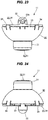
Figure 34 is a perspective view showing a pair of seats each provided with a reading lamp according to an embodiment of the present invention. - Hereinbelow, an embodiment representing the present invention will be explained with reference to the drawings.
-
Figures 1 to 8 show one embodiment of the present invention. - A lens for
illumination 50 according to the present embodiment includes a lens body 51, which distributes light incident from the light source in a predetermined direction or range. With the present embodiment, the lens body 51 alone constitutes the lens forillumination 50, however, the lens forillumination 50 may include the lens body 51 as a part of its structure. - As shown in
Figure 1 to Figure 8 , the lens body 51, which is the lens forillumination 50 itself, is in the shape of a solid bowl as shown in the figure, and is integrally formed of a transparent material, such as an acrylic resin or polycarbonate. The lens body 51 includes anincident face 510, which is provided in a recessed manner in a bottom apex part thereof, and which receives the light from anLED 41, theLED 41 being disposed opposite to the lens body 51 on the inner side of the bottom apex part as a light source (as shown inFigure 1 ); areflection face 520, which is provided on the inner side of the outer periphery, totally reflecting the light, having reached from theincident face 510; and anemission face 530, which is provided at the upper end of the lens body 51, being opposed to theincident face 510 and emits the light, having reached from thereflection face 520, to the outside. - As shown in
Figure 1 , in the lens body 51, theincident face 510, being located in the bottom apex part formed in a bowl shape, is comprised of afirst incident face 511, providing a bottom face formed about the optical axis of theLED 41, and asecond incident face 512, providing a side face surrounding thefirst incident face 511. Thefirst incident face 511 is formed concentrically with theLED 41 about the optical axis L thereof, being provided with an arcuate section convexed toward theLED 41. With thefirst incident face 511, the light from theLED 41 is advanced straight or bent in the lens body 51 to be passed through an internal region of the lens body 51 apart from thereflection face 520, and directed toward theinner region 531, being closer to the center, within theemission face 530. - The
second incident face 512 is disposed such that it surrounds the emitting side of theLED 41, being formed into a tapered section, thereby the diameter of the opening of the recessed part in the bottom apex part being made slightly larger than that of the outer periphery of thefirst incident face 511. Thesecond incident face 512 could be formed so as to refract the light from theLED 41 toward the entire region of thereflection face 520, but, it is formed so as to distribute such light only in a later-describedpredetermined range 521 within thereflection face 520, being adjacent to the upper end side portion (the upper portion 522), following theemission face 530, and being closer to the bottom apex part. Such light distribution control is previously established by setting the tapered angle of thesecond incident face 512. - The
reflection face 520 is provided as a critical angle reflection face with which the inner side of the outer periphery of the lens body 51 can totally reflect the light incident from thesecond incident face 512 toward theouter region 532, being closer to the outside, within theemission face 530. However, as described above, the light incident from thesecond incident face 512 will not reach the entire area of thereflection face 520, but will limitedly reach thepredetermined range 521, being closer to the bottom apex part, within thereflection face 520. Herein, specifically, thepredetermined range 521 corresponds to a part of thereflection face 520 the level of which ranges from the bottom apex part to, for example, two thirds of the overall height of the lens body 51. - The
reflection face 520 provides a series of slanted curved surfaces, however, by making a specific design of the curved geometry and the inclination angle of thepredetermined range 521, the light, having been totally reflected, can be caused to be irradiated from theemission face 530 in a desired direction or with a desired light distribution characteristic. In the present embodiment, as shown inFigure 1 , thepredetermined range 521 of thereflection face 520 is provided as a series of slanted curved surfaces, causing the reflected light to be condensed in a direction approximately in parallel with the optical axis L of theLED 41. InFigure 1 ,Figure 4 , andFigure 6 , thepredetermined range 521 and theupper portion 522 located thereabove of thereflection face 520 are shown with a symbol being given on the right or left side alone, however, it should be noted that the portion to which the symbol refers extends over the entire periphery to the opposite side (the left or right side in the figure) where no symbol is given. - The
emission face 530 is formed concentrically with theLED 41 about the optical axis L thereof, being provided with a curved section slightly bulged toward the outside, however, theemission face 530 may be formed in a flat surface. In the light distribution control in the present embodiment, theemission face 530 is divided into two regions, i.e., theinner region 531, which is closer to the center, and theouter region 532 therearound, however, such division is not provided visibly. Theinner region 531 provides a region where the light which has been made incident from thefirst incident face 511 is emitted directly to the outside. Theouter region 532 provides a region where the light which has been made incident from thesecond incident face 512 and totally reflected in thepredetermined range 521 of thereflection face 520 is emitted to the outside. - With the
lamp body 11 of the later-describedreading lamp 10, as shown inFigure 16 andFigure 17 , the lens forillumination 50 is disposed ahead of theLED 41 through theholder 53. Herein, theholder 53 is a member to hold the lens forillumination 50, being in a cylindrical shape on the whole and provided with aflange 54 around the opening at the rear end, and is integrally formed of a synthetic resin, such as a plastic material, by using a mold. Theholder 53 is located with a later-describedLED substrate 40 by means of a locating means. More specifically, as shown inFigure 16 andFigure 17 , theflange 54 of theholder 53 is provided with ahole part 55, into which aprojection 27 of abase 20 is fitted. - On the outside of outer periphery of the lens body 51, there is provided a shoulder part (mounted part) 52 to be located on the edge (mounting part) of the opening at the front end of the
holder 53. Within thereflection face 520 on the inner side of the outer periphery of the lens body 51, the lower portion thereof, which is located closer to the bottom apex part than theshoulder part 52, provides thepredetermined range 521. Strictly speaking, even thereflection face 520 is not capable of maintaining the total reflection in a portion thereof in which theshoulder part 52 is provided. - Within the outer periphery of the lens body 51, the upper portion thereof, including the
shoulder part 52, is fitted to the front of the inner periphery of theopening part 31 of a later-describedcover 30, with the top face of theshoulder part 52 being engaged with ashoulder part 32, which is provided on the the inner periphery of theopening part 31. In such a state, the lens body 51 is held between theholder 53 and theopening part 31. The lens body 51 is not contact with theholder 53 and thecover 30, except for theshoulder part 52 and the outer periphery, being located thereabove. - In the case where, with the lens for
illumination 50, the orientation in which it is to be assembled with a later-describedbase 20 has been predetermined, the lens forillumination 50 and theholder 53 can be provided with means for mutually regulating the assembling orientation, 52a and 56. More specifically, as shown inFigure 16 , anotch 52a is provided for the lens forillumination 50 in one place in theshoulder part 52. On the other hand, at the opening end of theholder 53, aprojection 56, which is matched to thenotch 52a, is provided in one place to assure the proper orientation of thenotch 52a in assembling. - Any assembling orientation in which the
projection 56 is not matched to thenotch 52a will cause theprojection 56 to interfere with theshoulder part 52 of the lens forillumination 50, thereby the lens forillumination 50 being unable to be assembled with theholder 53. With the lens forillumination 50 according to the present embodiment, the lens body 51 has the same sectional shape over the entire periphery except for theshoulder part 52, and thus the orientation thereof is not particularly specified, however, for a later-described lens forillumination 50A, thenotch 52a allows the orientation of the lens forillumination 50A to be easily determined, whereby assembling in an improper orientation can be prevented. -
Figure 9 to Figure 15 show a lens forillumination 50A according to a modification, which, although the basic geometry and size thereof are common to those of the above-described lens forillumination 50, is provided with a reflection face 520A, being different from that of thereflection face 520. Note that the same potions as those of the lens forillumination 50 are provided with the same numerals, respectively, and repeated explanation thereof will be omitted here. The lens forillumination 50A according to the present modification is also disposed ahead of theLED 41 through thesame holder 53, being held in thelamp body 11. - With the outer periphery of the
lens body 51A of the lens forillumination 50A, the area at least from the bottom apex part to a halfway point of thepredetermined range 521 is provided with a plurality of side faces 523, with which the cross section orthogonal to the axis thereof has a polygonal shape. Then, the light, being totally reflected by the reflection face 520A, which is provided on the inner side of eachside face 523, is emitted from theemission face 530 in an irradiation range having an outline of the polygonal shape. - More specifically, the outer periphery of the
lens body 51A is formed such that it has four side faces 523, being inclined at an equal angle from the bottom apex part. With such reflection face 520A, which is provided on the inner side of eachside face 523, the light, having reached from thesecond incident face 512 of theincident face 510, can be condensed into a quadrangle (square), whereby the light distribution from theemission face 530 can be performed for a quadrangle (square). - In the present modification, the lens for
illumination 50A is configured to have four side faces 523, being inclined at an equal angle from the bottom apex part within the outer periphery thereof toward four directions, however, the specific configuration of the lens forillumination 50A is not limited to that of the lens forillumination 50A according to the present modification, and the cross section of the lens body 51 may be specified to have a triangular shape or a five- or more-sided polygonal shape, for example. - Next, as shown in
Figure 16 to Figure 34 , a readinglamp 10, including the above-described lens forillumination lamp 10 according to the present embodiment provides a lighting fixture, which includes alamp body 11, having a lens forillumination lamp body 11 being mounted to aseat 1 through abracket 60. Hereinafter, the readinglamp 10, which has been provided for theseat 1 in a railroad vehicle, will be explained, being used as an example. - As shown in
Figure 16 andFigure 17 , thelamp body 11, constituting a critical part of the readinglamp 10, is provided by assembling thebase 20, with which the light source is disposed on the front side, with thecover 30, which surrounds the light source on the front side of thebase 20, except for the irradiation range. Thelamp body 11 is provided with a leg part, which is protruded on the side opposite to the emitting side of the light source, the tip thereof being engaged with a receivingpart 65, being provided for a later-described bracket 60 (seeFigure 29 ). Thelamp body 11 is supported by thebracket 60 such that the irradiation direction of the light source (the angle of the optical axis) can be adjusted with the tip of theleg part 22 being used as a fulcrum. - The
base 20 has a disk-like shape on the whole, being integrally formed of a metal, such as an aluminum alloy by using such a method as die casting. Thebase 20 is made of a metal, being excellent in thermal conductivity, thereby serving also as a heat sink for dissipating the heat of the light source. More specifically, thebase 20 has a disk-like shape on the front side, providing a mountingface 21, while being opened on the back side to have a shallow-bottom dish-like shape, theleg part 22 being provided at the center on the back side of the mountingface 21. - The
leg part 22 is formed in a shaft-like shape with the tip thereof having a semispherical shape, being protruded toward the back side perpendicularly with respect to the mounting face. The tip of theleg part 22 is protruded toward the outside from the end edge of theperipheral wall 23 surrounding a space on the back side of the mounting face 21 (from the reference surface on the back side of the base 20) by an amount equal to the height of theperipheral wall 23 when viewed from the side. In addition, the end edge of theperipheral wall 23 is provided with aflange 24, being extended sidewise. - On the back side of the
base 20, there is radially provided arib 25, being extended four directions from theleg part 22 as the center and joined to the inner side of theperipheral wall 23. Eachrib 25 serves not only to reinforce theleg part 22 and theperipheral wall 23, but also to function as a heat dissipation fin. InFigure 16 , in one section between twoadjacent ribs 25, theperipheral wall 23 and theflange 24 are notched for use as a mounting space where related components, such as a power circuit board and a light source control circuit board, are disposed. In one portion of theflange 24, which is opposed to this mounting space, there is provided alocating pin 24a, being protruded sidewise. - In addition, the
base 20 is provided with a later-described engagedpart 26, which is used for snap-fit engagement with thecover 30. Theengaged part 26 is disposed along the outer periphery edge of theflange 24 in each location where therib 25 is joined thereto. In the present embodiment, four engagedparts 26 are provided in correspondence to the fourribs 25. More specifically, as shown inFigure 25 , on the outer periphery edge of theflange 24, the engagedpart 26 is provided as an engaged groove, which is matched to the tip of an engaging claw of a later-describedengaging part 34 of thecover 30. - Next, the
cover 30 is in a semispherical bowl-shape on the whole, being integrally formed of a synthetic resin, such as a plastic material, by using a mold. Thecover 30 is formed of a synthetic resin, which is elastically deformable, and thus the later-describedengaging part 34 can be elastically deformed. In the apex part of the outer periphery of thecover 30, anopening part 31 for irradiation, matching to the irradiation range of the light source, is provided, being protruded in a cylinder-like manner. As shown inFigure 25 , in the inner periphery of theopening part 31, there is formed ashoulder part 32, with which the diameter of the inner periphery is contracted toward the tip. - The
cover 30 is assembled to the base 20 so as to cover the front side thereof. More specifically, an openingedge 33, which is the outermost periphery of thecover 30, is assembled to the base 20 so as to be fitted to the outer periphery edge of theflange 24, and they are fixed to each other by snap-fit engaging the engagingpart 34, being provided for thecover 30, with the engagedpart 26, being provided for thebase 20. Therefore, the inside diameter of the openingedge 33 of thecover 30 is designed to be that which is tightly matched to the outside diameter of theflange 24 of thebase 20. - The
cover 30 is provided with the engagingpart 34, which is to be snap-fit engaged with thebase 20. Along the openingedge 33, there are arranged a plurality of engagingpart 34, being disposed in the locations where they are matched to the engagedparts 26. In the present embodiment, in correspondence with the four engagedparts 26, the same number ofengaging parts 34 are provided. More specifically, as shown inFigure 25 , the engagingpart 34 is provided along the openingedge 33 as an engaging claw, being fitted to the engaged groove, which is the engagedpart 26. - As shown in
Figure 16 , the engaging claw, which is theengaging part 34, is formed such that the tip end of the claw is protruded toward the inside of the openingedge 33. Herein, the back of the tip end is formed in a tapered shape such that it can elastically get on the engaged groove, which is the engagedpart 26. In addition, on both sides of theengaging part 34, a pair of slits are notched such that a part of the outer periphery including the engagingpart 34 can be elastically deformed toward the outside. - Next, the light source, which is disposed on the front side of the base 20 in the
lamp body 11, will be explained. The light source is constituted by asingle LED 41, which is a semiconductor light-emitting element, being mounted on anLED substrate 40. TheLED substrate 40 is formed in a square having a size allowing it to be accommodated within the area of the mountingface 21 of thebase 20. As theLED 41, an LED chip of surface-mounting type is suitable, for example. Since the LED chip of such type is well known, the detailed explanation thereof will be omitted here. Simply put, it emits light within a predetermined angle of irradiation range about the optical axis thereof perpendicular to theLED substrate 40. The luminescent color can be arbitrarily selected to suit to the application and type of the lighting fixture, however, for the reading lamp, white color is suitable. - The
LED 41 is required to be held in a predetermined location on the front side of the base 20 in thelamp body 11. Then, on the mountingface 21 of thebase 20, there is provided a locating means for locating theLED substrate 40 when disposing it. More specifically, as shown inFigure 17 , on the mountingface 21, threeprojections 27 are provided. On the other hand, in the peripheral area of theLED substrate 40, there are providedhole parts 42, into which theprojections 27 are fitted, respectively. In thebase 20, aninsertion hole 28 for inserting a wiring to supply power to theLED substrate 40 from the outside power supply is also provided (seeFigure 17 ). - Between the mounting
face 21 of thebase 20 and theLED substrate 40, a packing 43 in a ring shape is interposed, and the mountingface 21 of thebase 20 and theLED substrate 40 are tightly contacted with each other through the packing 43. The packing 43 is integrally formed of an elastic material, such as a non-conductive silicone rubber. The packing 43 is a member for protecting the circuit on theLED substrate 41 as a cushioning material, and for improving the dissipation performance by enhancing the adhesion between the base 20 and theLED substrate 40. - The
lamp body 11, which provides a critical part of the above-describedreading lamp 10, is mounted to theseat 1 through thebracket 60. Herein, theseat 1 is, for example, a two-occupant seat for use in a railroad vehicle, with whichseat parts 2 andbackrests 3 for two persons are arranged side by side in a line, as shown inFigure 34 , and of both side parts on the upper end side of therespective backrests 3, on the side part, being located on the outer side of the seat, the readinglamp 10 is provided. The readinglamp 10 is mounted to a frame in the inside of thebackrest 3, the openingpart 31 thereof and the surrounding portion thereof being exposed to the outside of the cover of thebackrest 3. - As shown in
Figure 26 to Figure 33 , thebracket 60 displaceably holds thelamp body 11, having ahousing part 61 for accommodating thelamp body 11 on the inner side thereof, and mountingparts backrest 3. Thehousing part 61 is approximately in a cylindrical shape, surrounding theentire lamp body 11, except for theopening part 31, which provides the irradiation face of thelamp body 11, and is formed of such a material as a metal. - The
housing part 61 is comprised of anouter periphery wall 62, being approximately in a cylindrical shape, afront wall 63, covering the front-side opening of theouter periphery wall 62, and aback wall 64, walling up the back-face side opening of theouter periphery wall 62. The inside diameter of theouter periphery wall 62 is set at a size that allows thelamp body 11 to be accommodated so as to be displaceable. Thefront wall 63 is formed such that the outer periphery of thecover 30 is slidably butted against the inner side, and is provided with aguide opening 63a, into which theopening part 31 is movably inserted. - The
guide opening 63a is extended in a vertical direction, the inside diameter and the lateral width of theguide opening 63a at the upper and lower ends thereof being designed to be slightly larger than the outside diameter of theopening part 31. In addition, the peripheral edge of theguide opening 63a may be provided as another part made of a synthetic resin rather than a metal. Further, the inner side of the peripheral edge of theguide opening 63a may be provided with a holding member made of such a material as moquette, which is to be elastically butted against the outer periphery of thecover 30. When thelamp body 11 is to be accommodated in thehousing part 61, thefront wall 63 can be mounted later. - The
back wall 64 walls up the back side of thebase 20 of thelamp body 11, however, it is not formed in the shape of a disk on the whole, but is configured such that a plurality of supporting plates are radially extended from the central portion. In the central portion of thisback wall 64, there is provided a receivingpart 65, with which the tip of theleg part 22, being provided on the back side of thebase 20, is engaged. As shown inFigure 29 , the receivingpart 65 is formed by fitting a gromet made of a resin into a round hole produced in the central portion of theback wall 64. However, the configuration of the receivingpart 65 is not limited to this, and any other configuration may be provided, so long as it allows the tip of theleg part 22 to be used as a fulcrum, being engaged therewith. - The
lamp body 11, which has been accommodated in thehousing part 61, can be rocked in order to adjust the irradiation direction of theLED 41 with the use of the tip of theleg part 22, being engaged with the receivingpart 65, as a fulcrum. Herein, although, with thelamp body 11, the orientation of theopening part 31 can be changed in a variety of directions, such as the vertical, horizontal, and oblique ones, with the use of the tip of theleg part 22 as a turning center, however, in the present embodiment, the openingpart 31 is guided within theguide opening 63a, being extended in a vertical direction. Therefore, the displacement of thelamp body 11 is restricted to rocking in a vertical direction with the tip of theleg part 22 being used as a turning center, whereby the irradiation direction of theLED 41 can be adjusted vertically. - As described above, in the inside of the
housing part 61, the outer periphery of thecover 30 of thelamp body 11 is slidably butted against the inner side of thefront wall 63, and in addition, the outer periphery of theentire lamp body 11 is surrounded by theouter periphery wall 62, further, the tip of theleg part 22, being protruded from thebase 20 of thelamp body 11, being engaged with the receivingpart 65 of theback wall 64. In this way, thelamp body 11 is supported between thefront wall 63 and theback wall 64 of thebracket 60 so as to be displaceable with the tip of theleg part 22 being used as a fulcrum, the position thereof being held by the friction force, which is given in the supported state. - In addition, besides the
opening part 31 of thelamp body 11 being guided within the guide opening 63a of thebracket 60, the locatingpin 24a in thebase 20 is also guided by anelongated hole 66a, being provided for a later-described mounting part 66 (seeFigure 26 ). However, the guidance of the locatingpin 24a by theelongated hole 66a is not always needed, the locatingpin 24a and theelongated hole 66a mainly playing a role as components allowing the top and bottom portions of thelamp body 11 to be easily identified. - The mounting
parts bracket 60 are to be fixed to the frame inside of thebackrest 3, being configured as components separate from thehousing part 61 and retrofitted thereto. The mountingparts backrest 3. The number of mountingparts parts eaves part 68 is provided on the side of thefront wall 63 in thehousing part 61. Thiseaves part 68 is a portion for concealing a gap that may be produced in the mounting place, depending upon the geometry of the surface of thebackrest 3, in which thereading lamp 10 is disposed. - Next, the optical characteristics of the lens for
illumination 50 will be explained. As shown inFigure 1 , with the present lens forillumination 50, the lens body 51 distributes the light incident from theLED 41 in a predetermined direction or range. The light from theLED 41 is efficiently taken in into the inside of the lens body 51 from theincident face 510, being provided in a recessed manner in the bottom apex part of the lens body 51. Herein, the light from theLED 41 is advanced straight or bent to be passed through the inside of the lens body 51 in accordance with the angle with respect to theincident face 510. - More specifically, the
incident face 510 is comprised of afirst incident face 511, providing a bottom face of the recessed part, and asecond incident face 512, providing a side face of the recessed part, both incident faces being different from each other in the light distribution characteristics. Thereby, the light from theLED 41 can be efficiently utilized. The light incident from thefirst incident face 511 is advanced straight or bent so as to be passed through an internal region of the lens body 51 apart from thereflection face 520, and emitted to the outside from theinner region 531 of theemission face 530. - In addition, the light incident from the
second incident face 512 is advanced straight or bent toward thepredetermined range 521, being closer to the bottom apex part, within thereflection face 520 in the lens body 51. Then, the light, which has been totally reflected in thepredetermined range 521 of thereflection face 520, is condensed in a direction approximately in parallel with the optical axis L of theLED 41, being emitted to the outside from theouter region 532 of theemission face 530. - In this way, the
second incident face 512 refracts the light from theLED 41 toward thereflection face 520, however, it will not refract the light toward the entire area of thereflection face 520, but will distribute the light only in thepredetermined range 521, which is closer to the bottom apex part. With such a method of light distribution control, even if the passenger obliquely views theemission face 530, which closes theopening part 31, even thepredetermined range 521, being located in the deeper area of thereflection face 520, will not come into view, so long as the passenger does not intentionally peek deep into the lens body 51. Therefore, within thetotal reflection face 520 of the lens body 51, theupper portion 522 alone, from which the light will not be reflected, will normally enter the visual field, whereby uncomfortable glare can be suppressed. - By the way, as the irradiation range of the light that is to be provided by the reading
lamp 10, a quadrangle, corresponding to the shape of a magazine read by the seated person or the seat table, will be sufficient, however, with the conventional general reading lamp, light distribution in a circular shape, which includes a quadrangle, has been performed. With such light distribution in a circular shape, the distribution of light in the segment between the chord and the arc, which is produced on the outside of each side of a quadrangle inscribed in the circle, will be surplus. - Especially with the reading
lamp 10, which is applied to theseat 1 for use in a railroad vehicle, such surplus light distribution has presented a problem, such as it being directed toward the aisle on the lateral side of theseat 1 or the passenger on the front seat. Then, instead of using a method for obstructing the surplus light, by adapting the lens forillumination 50 itself to devise a lens forillumination 50A for modifying the irradiation range such that the light is originally distributed in a quadrangle, as described above, the light from theLED 41 can be efficiently utilized without wasting it. - More specifically, the outer periphery of the
lens body 51A has four side faces 523, which are inclined at an equal angle in four directions from the bottom apex part thereof. With such reflection face 520A, which is provided on the inner side of eachside face 523, the light, having reached from thesecond incident face 512 of theincident face 510, can be condensed into a quadrangle (square), whereby the light distribution from theemission face 530 can be performed for a quadrangle (square). - Next, the characteristic action of the reading
lamp 10 according to the present embodiment will be explained. - As shown in
Figure 29 , on the back side of thebase 20 of thelamp body 11, theleg part 22 is protruded, the tip of thisleg part 22 being engaged with the receivingpart 65 in thehousing part 61. Thelamp body 11 can be rocked in thehousing part 61 with the use of the tip of theleg part 22 as a fulcrum, whereby the irradiation direction of the LED 41can be adjusted. With such alamp body 11, the entire shape need not be a sphere as with the conventional technology. - As shown in
Figure 25 , for thebase 20 of thelamp body 11, the shape may be basically a disk-like simple one, allowing theLED 41 to be disposed on the front side thereof, with only theleg part 22 being locally protruded from the reference surface on the back side thereof. Accordingly, the shape of thelamp body 11 can be made non-bulky and compact, and thebracket 60, supporting thelamp body 11, can also be downsized. With thecover 30, being assembled with the front side of thebase 20, the inside space of thelamp body 11 is secured. - As shown in
Figure 29 , thefront wall 63 of thebracket 60 is formed such that the outer periphery of thecover 30 is slidably butted against the inner side thereof, whereby thecover 30, which provides the front side of thelamp body 11, can be positively held. In the apex part of the outer periphery of thecover 30, the openingpart 31 for irradiation is cylindrically protruded, being inserted into theguide opening 63a in thefront wall 63, whereby it can be rocked in a vertical direction. - In other words, the rocking of the
lamp body 11 is restricted to that in a vertical direction, using the tip of theleg part 22 as a turning center, and thus the irradiation direction of theLED 41 can be adjusted only in a vertical direction. The openingpart 31 of thelamp body 11 is protruded to the outside from the guide opening 63a of thefront wall 63, thisopening part 31 serving as an operation part for moving thelamp body 11 by hand. Herein, the tip of theleg part 22, which provides the inclination center of thebase 20, also provides the turning center of the optical axis of theLED 41 as it is, and thus adjustment of the irradiation direction of theLED 41 can be carried out while recognizing it with intuition. - In addition, the
base 20 is integrally formed of a metal, also serving as a heat sink. Thereby, dissipation of the heat of theLED 41, which is heated by luminescence, and theLED substrate 40 can be efficiently performed, whereby the temperature rise of theLED 41 and theLED substrate 40 can be suppressed. TheLED 41, which is disposed at the center of the front side of thebase 20, and theleg part 22, which plays especially as a role of a heat dissipation fin on the back side of thebase 20, are matched with each other in location on the front and back sides of thebase 20, and yet around theleg part 22, a plurality ofribs 25 are radially provided, whereby the heat dissipation can be further enhanced. - Next, assembling of the reading
lamp 10 according to the present embodiment will be explained. - In order to assemble the
lamp body 11, which provides a critical part of the readinglamp 10, theLED substrate 40 is first disposed on the mountingface 21 of the base 20 as shown inFigure 16 andFigure 17 . The mountingface 21 is provided withprojections 27 as a locating means. By matching theprojections 27 to theholes 42 in theLED substrate 40 such that they are fitted with each other, respectively, theLED 41 on theLED substrate 40 can be easily located. At this time, between the mountingface 21 of thebase 20 and theLED substrate 40, a packing 43 is interposed. - Next, above the mounting
face 21 of thebase 20, theholder 53, holding the lens forillumination 50, is disposed on theLED substrate 40 in such a way that the former is superposed on the latter. Since theholder 53 is also provided withhole parts 55, into which therespective projection 27 are to be fitted, theholder 53 and the lens forillumination 50 can also be easily located. At this time, there is no need for theholder 53 being bonded onto theLED substrate 40 or the lens forillumination 50 being bonded to theholder 53. - Finally, the
cover 30 is assembled to the base 20 in such a way that the latter is covered with the former from above theholder 53 of the lens forillumination 50. Herein, the openingedge 33 of thecover 30 is matched to the outer periphery edge of theflange 24 of thebase 20, the engagingparts 34 on thecover 30 being snap-fit engaged with the engagedparts 26 on thebase 20, thereby they being fixed to each other. Therefore, in assembling thelamp body 11, there is no need for using a fixing means such as an adhesive of a screw, and the assembly thereof can be made easily by simply utilizing the respective structures of thebase 20 and thecover 30. - Herein, how the above-mentioned snap-fit engaging is carried out will be explained in detail: as shown in
Figure 25 , with the engaging claw, which provides theengaging part 34 of thecover 30, the claw tip thereof is expanded such that it gets on the outer periphery edge of theflange 24 of thebase 20, while being elastically deformed. Then, when the claw tip of theengaging part 34 has reached the engaged groove, which provides theengaged part 26, the engaging claw is fitted into the engaged groove, while being returned to the original state, thus it completing the snap-fit engaging. - In this way, simply by making an operation of matching the
cover 30 to the base 20 such that the former covers the latter, the snap-fit engaging will be completed in due course in association with such operation with no need for making an extra operation, such as separately deforming the engagingpart 34 with the use of a tool, or the like. Yet, with the lens forillumination 50 in theholder 53, the portion above theshoulder part 52 of the outer periphery thereof is fitted to the inner periphery of theopening part 31 of thecover 30, with the top face of theshoulder part 52 being engaged with the stepped face of theshoulder part 32 of the inner periphery of theopening part 31. In such a state, the lens body 51 is held between theholder 53 and theopening part 31. - In the assembled
lamp body 11, not only the lens forillumination 50 and theholder 53, but also theLED substrate 40 and the packing 43 are held in place, being engaged with each other. Thereby, simply by assembling the base 20 with thecover 30, the component parts provided in the inside thereof can be fixed in the respective proper locations with a pressing force, being generated as a result of engaging with each other. In addition, theemission face 530 of the lens forillumination 50 is matched to theopening part 31 to block it, and thus there is no need for separately preparing such a part as a transparent protection cover to cover theopening part 31. - The
lamp body 11, which has been thus assembled, is accommodated in thehousing part 61 of thebracket 60 as described above for completion of a readinglamp 10. In this way, thelamp body 11 is handled as one unit of the readinglamp 10, together with thebracket 60. Then, the readinglamp 10 is fixed to the frame in thebackrest 3 of theseat 1 through the mountingparts bracket 60 to thereby be offered to use by a seated person. - When the reading
lamp 10 is to be used, theLED 41, which is the light source, is turned on by means of a switch (not shown). Then, for adjusting the irradiation direction of theLED 41, a finger is hooked on theopening part 31, being protruded to the outside of thehousing part 61, to press it with an operating force exceeding the above-mentioned friction force, which holds thelamp body 11 in a stationary state. At this time, thelamp body 11 is rocked in a vertical direction with the tip of theleg part 22 of the base 20 being used as the turning center, and thus by leaving the hand from the openingpart 31 at the point of time when it has been rocked to the desired irradiation direction, thelamp body 11 can be stopped in the relevant position. - Heretofore, the embodiment of the present invention has been described with reference to the drawings, however, the specific configuration is not limited to that of the embodiment as described above, and various changes and modifications may be included in the present invention, so long as they do not depart from the spirit and scope thereof. For example, for the lenses for
illumination incident face 510, the reflection faces 520 and 520A and thepredetermined range 521 thereof, and the specific geometry and configuration of theemission face 530 are not limited to those shown, but can be altered as appropriate. - In addition, the lenses for
illumination lamp 10. In addition, theseat 1, being provided with a readinglamp 10, including a lens forillumination seat 1, the readinglamp 10 may be provided in such a place as the ceiling or the side wall such that it illuminates theseat 1. - In addition, the specific geometry of a component constituting the reading
lamp 10, such as thelamp body 11 or thebracket 60, is not limited to that illustrated. In addition, for theLED 41 and thesubstrate 40 thereof, being contained in thelamp body 11, those which have various configurations other than illustrated may be adopted. In addition, the adjustability of the irradiation direction of the light source is not limited to the vertical direction, and may be adapted such that it is the horizontal direction or any specific angular direction as required. - Further, with the
lamp body 11, thecover 30 is provided with the engagingpart 34, while the base 20 being provided with the engagedpart 26, however, as an inverted aspect of the present embodiment, it may be configured such that thecover 30 is provided with the engagedpart 26, while the base 20 being provided with the engagingpart 34. Herein, the engagingpart 34 is not limited to a claw-like one, and theengaged part 26 is not limited to a groove-like one into which the above-mentioned claw is fitted. - The lens for illumination of the present invention is widely applicable also to various illuminators other than the reading lamp as an optical part thereof.
-
Reference numeral
Claims (5)
- A lens for illumination (50) adapted to be used as a component of a lighting device, distributing light incident from a light source (41) of the lighting device in a predetermined direction or range, comprising:a lens body (51) including an incident face (510), a reflection face (520),
and an emission face (530); whereinthe incident face (510) is formed in a recessed shape in a bottom apex part of said lens body (51) to receive light emitted from the light source (41) disposed in a space defined by the recessed shape;the reflection face (520) is formed on an inner side of an outer periphery of said lens body (51), so as to totally reflect the light coming from said incident face (510); andthe emission face (530) is formed on an upper end of said lens body (51), so as to emit the light coming from said incident face (510) and said reflection face (520) to the outside of the lens body (51), andwherein said incident face (510) is partly formed so as to distribute the light coming from the light source (41) only in a predetermined range (521) within the reflection face (520) defined between an upper end side portion of the reflection face (520) adjacent to said emission face (530), and a lower end side portion of the reflection face (520) adjacent to the bottom apex part of said lens body (51). - The lens for illumination (50A) according to claim 1, wherein the outer periphery of said lens body (51A) is provided with a plurality of side faces (523), extending at least from the bottom apex part of said lens body (51A) to a halfway point of said predetermined range (521), and
wherein each side face (523) is formed in a polygonal shape in the cross section orthogonal to an optical axis of the lens (50A), and the light totally reflected by said reflection face (520A) on an inner side of each side face (523) is emitted from said emission face (530) in an irradiation range having an outline of said polygonal shape. - The lens for illumination (50) according to claim 1 or 2, wherein said incident face (510) includes a first incident face (511) defined by a bottom face formed about the optical axis, and a second incident face (512) defined by a side face surrounding the first incident face (511),
wherein the first incident face (511) is formed to direct the light incident from said light source (41) to be passed through an internal region of the lens body (51) apart from said reflection face (520), and emitted to the outside of the lens body (51) from an inner region (531) adjacent to the center of said emission face (530), and
wherein the second incident face (512) is formed to direct the light incident from said light source (41) to be passed through the internal region of the lens body (51), and totally reflected in said predetermined range (521) within said reflection face (520), and emitted to the outside of the lens body (51) from an outer region (532) of said emission face (530) around said inner region (531). - The lens for illumination (50) according to any one of claims 1 to 3, wherein, on the outside of the outer periphery of said lens body (51), there is provided a lens-mounting portion (52) for locating the lens body (51) with respect to the lighting device.
- The lens for illumination (50) according to any one of claims 1 to 4, wherein said lens body (51) constitutes a reading lamp (10) mounted on a seat (1).
Applications Claiming Priority (2)
| Application Number | Priority Date | Filing Date | Title |
|---|---|---|---|
| JP2018043638A JP7059052B2 (en) | 2018-03-09 | 2018-03-09 | Illumination lens |
| PCT/JP2019/009412 WO2019172436A1 (en) | 2018-03-09 | 2019-03-08 | Illumination lens |
Publications (3)
| Publication Number | Publication Date |
|---|---|
| EP3763995A1 true EP3763995A1 (en) | 2021-01-13 |
| EP3763995A4 EP3763995A4 (en) | 2021-01-27 |
| EP3763995B1 EP3763995B1 (en) | 2024-09-11 |
Family
ID=67847230
Family Applications (1)
| Application Number | Title | Priority Date | Filing Date |
|---|---|---|---|
| EP19764305.9A Active EP3763995B1 (en) | 2018-03-09 | 2019-03-08 | Illumination lens |
Country Status (6)
| Country | Link |
|---|---|
| US (1) | US11105489B2 (en) |
| EP (1) | EP3763995B1 (en) |
| JP (1) | JP7059052B2 (en) |
| CN (1) | CN111989520B (en) |
| TW (1) | TWI794435B (en) |
| WO (1) | WO2019172436A1 (en) |
Families Citing this family (2)
| Publication number | Priority date | Publication date | Assignee | Title |
|---|---|---|---|---|
| WO2021182562A1 (en) * | 2020-03-13 | 2021-09-16 | 株式会社小糸製作所 | Reading light |
| JP2025180236A (en) * | 2024-05-29 | 2025-12-11 | パナソニックIpマネジメント株式会社 | Vehicle and interior lighting devices |
Family Cites Families (20)
| Publication number | Priority date | Publication date | Assignee | Title |
|---|---|---|---|---|
| US6598998B2 (en) * | 2001-05-04 | 2003-07-29 | Lumileds Lighting, U.S., Llc | Side emitting light emitting device |
| JP2005129354A (en) | 2003-10-23 | 2005-05-19 | Toshiba Lighting & Technology Corp | LED lighting device |
| EP1693614B1 (en) * | 2003-12-10 | 2009-12-16 | Okaya Electric Industries Co., Ltd. | Indicator lamp |
| JP2005347224A (en) | 2004-06-07 | 2005-12-15 | Olympus Corp | Light source device |
| JP4670801B2 (en) | 2006-11-30 | 2011-04-13 | 東芝ライテック株式会社 | lighting equipment |
| KR100756174B1 (en) * | 2007-02-20 | 2007-09-05 | 주식회사 세코닉스 | Condensing Lens for LED |
| US8231250B2 (en) * | 2007-09-10 | 2012-07-31 | Lighting Science Group Corporation | Warm white lighting device |
| JP5332770B2 (en) * | 2008-04-18 | 2013-11-06 | 東芝ライテック株式会社 | lighting equipment |
| JP5439017B2 (en) | 2009-04-14 | 2014-03-12 | 株式会社エンプラス | LIGHTING LENS AND LIGHTING DEVICE HAVING THE SAME |
| JP2014525656A (en) * | 2011-09-06 | 2014-09-29 | コーニンクレッカ フィリップス エヌ ヴェ | Diagonal lighting fixture |
| JP2013171802A (en) | 2012-02-22 | 2013-09-02 | Stanley Electric Co Ltd | Led lighting device and light guide lens |
| JP2014120296A (en) * | 2012-12-14 | 2014-06-30 | Toshiba Lighting & Technology Corp | Lighting device, lamp device and lens |
| CN104885239A (en) * | 2013-01-04 | 2015-09-02 | 韩国艾尼凯斯特有限公司 | Side emitting light emitting diode lens, back light unit and display device including the same |
| TW201500691A (en) * | 2013-06-28 | 2015-01-01 | 鴻海精密工業股份有限公司 | Lens, light source device incorporating the same and light source module incorporating the same |
| WO2016051863A1 (en) | 2014-09-30 | 2016-04-07 | 三菱電機株式会社 | Lighting device |
| US10801696B2 (en) * | 2015-02-09 | 2020-10-13 | Ecosense Lighting Inc. | Lighting systems generating partially-collimated light emissions |
| JP6698376B2 (en) | 2016-02-26 | 2020-05-27 | 大光電機株式会社 | Lighting fixture and manufacturing method thereof |
| DE102016109159A1 (en) * | 2016-05-18 | 2017-11-23 | SMR Patents S.à.r.l. | Lens and method of making a lens |
| CN106523958A (en) * | 2016-12-30 | 2017-03-22 | 广州市戴亚萌光学仪器有限责任公司 | Secondary lens for forming annular light spots |
| WO2018141846A1 (en) * | 2017-02-02 | 2018-08-09 | Philips Lighting Holding B.V. | A dielectric collimator with a rejecting center lens |
-
2018
- 2018-03-09 JP JP2018043638A patent/JP7059052B2/en active Active
-
2019
- 2019-03-07 TW TW108107534A patent/TWI794435B/en active
- 2019-03-08 CN CN201980017762.3A patent/CN111989520B/en active Active
- 2019-03-08 EP EP19764305.9A patent/EP3763995B1/en active Active
- 2019-03-08 US US16/979,315 patent/US11105489B2/en active Active
- 2019-03-08 WO PCT/JP2019/009412 patent/WO2019172436A1/en not_active Ceased
Also Published As
| Publication number | Publication date |
|---|---|
| WO2019172436A1 (en) | 2019-09-12 |
| EP3763995A4 (en) | 2021-01-27 |
| JP7059052B2 (en) | 2022-04-25 |
| TWI794435B (en) | 2023-03-01 |
| CN111989520A (en) | 2020-11-24 |
| EP3763995B1 (en) | 2024-09-11 |
| JP2019160500A (en) | 2019-09-19 |
| CN111989520B (en) | 2022-11-29 |
| TW201943996A (en) | 2019-11-16 |
| US20210062997A1 (en) | 2021-03-04 |
| US11105489B2 (en) | 2021-08-31 |
Similar Documents
| Publication | Publication Date | Title |
|---|---|---|
| JP4500273B2 (en) | Vehicle headlamp | |
| EP2378323B1 (en) | Vehicle lamp | |
| US10253939B2 (en) | Lighting device for vehicle | |
| JP2016524285A (en) | Lighting device for vehicle headlight | |
| JP2010205660A (en) | Lighting equipment | |
| EP3763995B1 (en) | Illumination lens | |
| JP7218144B2 (en) | reading light | |
| JP6607620B1 (en) | Vehicle lighting | |
| US10174888B1 (en) | Modular lighting unit | |
| JP6590996B1 (en) | Vehicle lighting | |
| JP4835605B2 (en) | Vehicle lighting | |
| JP2007265688A (en) | Collimation lens and illumination device using the same | |
| KR20110055914A (en) | LED Optics for Headlamps | |
| JP6713793B2 (en) | Lighting module | |
| JP2009199780A (en) | Lighting fixture for vehicle | |
| JP2017021918A (en) | Luminaire | |
| US10912168B2 (en) | LED light apparatus | |
| JP7065316B2 (en) | Lighting equipment and lenses | |
| JP2018045978A (en) | Lamp unit | |
| JP6577631B1 (en) | Vehicle lighting | |
| JP2008112582A (en) | lighting equipment | |
| JP2019212635A (en) | Vehicle lamp | |
| CN215929372U (en) | Lighting apparatus | |
| CN114144613B (en) | Lighting | |
| JP2019212633A (en) | Vehicle lamp |
Legal Events
| Date | Code | Title | Description |
|---|---|---|---|
| STAA | Information on the status of an ep patent application or granted ep patent |
Free format text: STATUS: THE INTERNATIONAL PUBLICATION HAS BEEN MADE |
|
| PUAI | Public reference made under article 153(3) epc to a published international application that has entered the european phase |
Free format text: ORIGINAL CODE: 0009012 |
|
| STAA | Information on the status of an ep patent application or granted ep patent |
Free format text: STATUS: REQUEST FOR EXAMINATION WAS MADE |
|
| 17P | Request for examination filed |
Effective date: 20201007 |
|
| AK | Designated contracting states |
Kind code of ref document: A1 Designated state(s): AL AT BE BG CH CY CZ DE DK EE ES FI FR GB GR HR HU IE IS IT LI LT LU LV MC MK MT NL NO PL PT RO RS SE SI SK SM TR |
|
| AX | Request for extension of the european patent |
Extension state: BA ME |
|
| A4 | Supplementary search report drawn up and despatched |
Effective date: 20210112 |
|
| RIC1 | Information provided on ipc code assigned before grant |
Ipc: F21V 5/00 20180101AFI20201221BHEP Ipc: B60Q 3/72 20170101ALI20201221BHEP Ipc: G02B 19/00 20060101ALI20201221BHEP Ipc: B60Q 3/233 20170101ALI20201221BHEP Ipc: F21Y 115/10 20160101ALN20201221BHEP Ipc: B60Q 3/60 20170101ALI20201221BHEP Ipc: F21V 5/04 20060101ALI20201221BHEP Ipc: B60Q 3/44 20170101ALI20201221BHEP |
|
| DAV | Request for validation of the european patent (deleted) | ||
| DAX | Request for extension of the european patent (deleted) | ||
| STAA | Information on the status of an ep patent application or granted ep patent |
Free format text: STATUS: EXAMINATION IS IN PROGRESS |
|
| 17Q | First examination report despatched |
Effective date: 20220624 |
|
| GRAP | Despatch of communication of intention to grant a patent |
Free format text: ORIGINAL CODE: EPIDOSNIGR1 |
|
| STAA | Information on the status of an ep patent application or granted ep patent |
Free format text: STATUS: GRANT OF PATENT IS INTENDED |
|
| RIC1 | Information provided on ipc code assigned before grant |
Ipc: F21Y 115/10 20160101ALN20240426BHEP Ipc: G02B 19/00 20060101ALI20240426BHEP Ipc: F21V 5/04 20060101ALI20240426BHEP Ipc: B60Q 3/72 20170101ALI20240426BHEP Ipc: B60Q 3/60 20170101ALI20240426BHEP Ipc: B60Q 3/44 20170101ALI20240426BHEP Ipc: B60Q 3/233 20170101ALI20240426BHEP Ipc: F21V 5/00 20180101AFI20240426BHEP |
|
| INTG | Intention to grant announced |
Effective date: 20240516 |
|
| RAP3 | Party data changed (applicant data changed or rights of an application transferred) |
Owner name: KOITO ELECTRIC INDUSTRIES, LTD. |
|
| GRAS | Grant fee paid |
Free format text: ORIGINAL CODE: EPIDOSNIGR3 |
|
| GRAA | (expected) grant |
Free format text: ORIGINAL CODE: 0009210 |
|
| STAA | Information on the status of an ep patent application or granted ep patent |
Free format text: STATUS: THE PATENT HAS BEEN GRANTED |
|
| AK | Designated contracting states |
Kind code of ref document: B1 Designated state(s): AL AT BE BG CH CY CZ DE DK EE ES FI FR GB GR HR HU IE IS IT LI LT LU LV MC MK MT NL NO PL PT RO RS SE SI SK SM TR |
|
| REG | Reference to a national code |
Ref country code: GB Ref legal event code: FG4D |
|
| REG | Reference to a national code |
Ref country code: CH Ref legal event code: EP |
|
| REG | Reference to a national code |
Ref country code: DE Ref legal event code: R096 Ref document number: 602019058729 Country of ref document: DE |
|
| REG | Reference to a national code |
Ref country code: IE Ref legal event code: FG4D |
|
| REG | Reference to a national code |
Ref country code: LT Ref legal event code: MG9D |
|
| PG25 | Lapsed in a contracting state [announced via postgrant information from national office to epo] |
Ref country code: NO Free format text: LAPSE BECAUSE OF FAILURE TO SUBMIT A TRANSLATION OF THE DESCRIPTION OR TO PAY THE FEE WITHIN THE PRESCRIBED TIME-LIMIT Effective date: 20241211 |
|
| REG | Reference to a national code |
Ref country code: NL Ref legal event code: MP Effective date: 20240911 |
|
| PG25 | Lapsed in a contracting state [announced via postgrant information from national office to epo] |
Ref country code: GR Free format text: LAPSE BECAUSE OF FAILURE TO SUBMIT A TRANSLATION OF THE DESCRIPTION OR TO PAY THE FEE WITHIN THE PRESCRIBED TIME-LIMIT Effective date: 20241212 Ref country code: FI Free format text: LAPSE BECAUSE OF FAILURE TO SUBMIT A TRANSLATION OF THE DESCRIPTION OR TO PAY THE FEE WITHIN THE PRESCRIBED TIME-LIMIT Effective date: 20240911 |
|
| PG25 | Lapsed in a contracting state [announced via postgrant information from national office to epo] |
Ref country code: BG Free format text: LAPSE BECAUSE OF FAILURE TO SUBMIT A TRANSLATION OF THE DESCRIPTION OR TO PAY THE FEE WITHIN THE PRESCRIBED TIME-LIMIT Effective date: 20240911 |
|
| PG25 | Lapsed in a contracting state [announced via postgrant information from national office to epo] |
Ref country code: LV Free format text: LAPSE BECAUSE OF FAILURE TO SUBMIT A TRANSLATION OF THE DESCRIPTION OR TO PAY THE FEE WITHIN THE PRESCRIBED TIME-LIMIT Effective date: 20240911 |
|
| PG25 | Lapsed in a contracting state [announced via postgrant information from national office to epo] |
Ref country code: HR Free format text: LAPSE BECAUSE OF FAILURE TO SUBMIT A TRANSLATION OF THE DESCRIPTION OR TO PAY THE FEE WITHIN THE PRESCRIBED TIME-LIMIT Effective date: 20240911 |
|
| PG25 | Lapsed in a contracting state [announced via postgrant information from national office to epo] |
Ref country code: RS Free format text: LAPSE BECAUSE OF FAILURE TO SUBMIT A TRANSLATION OF THE DESCRIPTION OR TO PAY THE FEE WITHIN THE PRESCRIBED TIME-LIMIT Effective date: 20241211 Ref country code: ES Free format text: LAPSE BECAUSE OF FAILURE TO SUBMIT A TRANSLATION OF THE DESCRIPTION OR TO PAY THE FEE WITHIN THE PRESCRIBED TIME-LIMIT Effective date: 20240911 |
|
| PG25 | Lapsed in a contracting state [announced via postgrant information from national office to epo] |
Ref country code: RS Free format text: LAPSE BECAUSE OF FAILURE TO SUBMIT A TRANSLATION OF THE DESCRIPTION OR TO PAY THE FEE WITHIN THE PRESCRIBED TIME-LIMIT Effective date: 20241211 Ref country code: NO Free format text: LAPSE BECAUSE OF FAILURE TO SUBMIT A TRANSLATION OF THE DESCRIPTION OR TO PAY THE FEE WITHIN THE PRESCRIBED TIME-LIMIT Effective date: 20241211 Ref country code: LV Free format text: LAPSE BECAUSE OF FAILURE TO SUBMIT A TRANSLATION OF THE DESCRIPTION OR TO PAY THE FEE WITHIN THE PRESCRIBED TIME-LIMIT Effective date: 20240911 Ref country code: HR Free format text: LAPSE BECAUSE OF FAILURE TO SUBMIT A TRANSLATION OF THE DESCRIPTION OR TO PAY THE FEE WITHIN THE PRESCRIBED TIME-LIMIT Effective date: 20240911 Ref country code: GR Free format text: LAPSE BECAUSE OF FAILURE TO SUBMIT A TRANSLATION OF THE DESCRIPTION OR TO PAY THE FEE WITHIN THE PRESCRIBED TIME-LIMIT Effective date: 20241212 Ref country code: FI Free format text: LAPSE BECAUSE OF FAILURE TO SUBMIT A TRANSLATION OF THE DESCRIPTION OR TO PAY THE FEE WITHIN THE PRESCRIBED TIME-LIMIT Effective date: 20240911 Ref country code: ES Free format text: LAPSE BECAUSE OF FAILURE TO SUBMIT A TRANSLATION OF THE DESCRIPTION OR TO PAY THE FEE WITHIN THE PRESCRIBED TIME-LIMIT Effective date: 20240911 Ref country code: BG Free format text: LAPSE BECAUSE OF FAILURE TO SUBMIT A TRANSLATION OF THE DESCRIPTION OR TO PAY THE FEE WITHIN THE PRESCRIBED TIME-LIMIT Effective date: 20240911 |
|
| REG | Reference to a national code |
Ref country code: AT Ref legal event code: MK05 Ref document number: 1722993 Country of ref document: AT Kind code of ref document: T Effective date: 20240911 |
|
| PG25 | Lapsed in a contracting state [announced via postgrant information from national office to epo] |
Ref country code: NL Free format text: LAPSE BECAUSE OF FAILURE TO SUBMIT A TRANSLATION OF THE DESCRIPTION OR TO PAY THE FEE WITHIN THE PRESCRIBED TIME-LIMIT Effective date: 20240911 |
|
| PG25 | Lapsed in a contracting state [announced via postgrant information from national office to epo] |
Ref country code: IS Free format text: LAPSE BECAUSE OF FAILURE TO SUBMIT A TRANSLATION OF THE DESCRIPTION OR TO PAY THE FEE WITHIN THE PRESCRIBED TIME-LIMIT Effective date: 20250111 Ref country code: PT Free format text: LAPSE BECAUSE OF FAILURE TO SUBMIT A TRANSLATION OF THE DESCRIPTION OR TO PAY THE FEE WITHIN THE PRESCRIBED TIME-LIMIT Effective date: 20250113 |
|
| PG25 | Lapsed in a contracting state [announced via postgrant information from national office to epo] |
Ref country code: SM Free format text: LAPSE BECAUSE OF FAILURE TO SUBMIT A TRANSLATION OF THE DESCRIPTION OR TO PAY THE FEE WITHIN THE PRESCRIBED TIME-LIMIT Effective date: 20240911 Ref country code: RO Free format text: LAPSE BECAUSE OF FAILURE TO SUBMIT A TRANSLATION OF THE DESCRIPTION OR TO PAY THE FEE WITHIN THE PRESCRIBED TIME-LIMIT Effective date: 20240911 |
|
| PG25 | Lapsed in a contracting state [announced via postgrant information from national office to epo] |
Ref country code: EE Free format text: LAPSE BECAUSE OF FAILURE TO SUBMIT A TRANSLATION OF THE DESCRIPTION OR TO PAY THE FEE WITHIN THE PRESCRIBED TIME-LIMIT Effective date: 20240911 Ref country code: AT Free format text: LAPSE BECAUSE OF FAILURE TO SUBMIT A TRANSLATION OF THE DESCRIPTION OR TO PAY THE FEE WITHIN THE PRESCRIBED TIME-LIMIT Effective date: 20240911 |
|
| PG25 | Lapsed in a contracting state [announced via postgrant information from national office to epo] |
Ref country code: CZ Free format text: LAPSE BECAUSE OF FAILURE TO SUBMIT A TRANSLATION OF THE DESCRIPTION OR TO PAY THE FEE WITHIN THE PRESCRIBED TIME-LIMIT Effective date: 20240911 Ref country code: PL Free format text: LAPSE BECAUSE OF FAILURE TO SUBMIT A TRANSLATION OF THE DESCRIPTION OR TO PAY THE FEE WITHIN THE PRESCRIBED TIME-LIMIT Effective date: 20240911 |
|
| PG25 | Lapsed in a contracting state [announced via postgrant information from national office to epo] |
Ref country code: IT Free format text: LAPSE BECAUSE OF FAILURE TO SUBMIT A TRANSLATION OF THE DESCRIPTION OR TO PAY THE FEE WITHIN THE PRESCRIBED TIME-LIMIT Effective date: 20240911 Ref country code: SK Free format text: LAPSE BECAUSE OF FAILURE TO SUBMIT A TRANSLATION OF THE DESCRIPTION OR TO PAY THE FEE WITHIN THE PRESCRIBED TIME-LIMIT Effective date: 20240911 |
|
| REG | Reference to a national code |
Ref country code: DE Ref legal event code: R097 Ref document number: 602019058729 Country of ref document: DE |
|
| PG25 | Lapsed in a contracting state [announced via postgrant information from national office to epo] |
Ref country code: DK Free format text: LAPSE BECAUSE OF FAILURE TO SUBMIT A TRANSLATION OF THE DESCRIPTION OR TO PAY THE FEE WITHIN THE PRESCRIBED TIME-LIMIT Effective date: 20240911 |
|
| PLBE | No opposition filed within time limit |
Free format text: ORIGINAL CODE: 0009261 |
|
| STAA | Information on the status of an ep patent application or granted ep patent |
Free format text: STATUS: NO OPPOSITION FILED WITHIN TIME LIMIT |
|
| 26N | No opposition filed |
Effective date: 20250612 |
|
| PG25 | Lapsed in a contracting state [announced via postgrant information from national office to epo] |
Ref country code: SE Free format text: LAPSE BECAUSE OF FAILURE TO SUBMIT A TRANSLATION OF THE DESCRIPTION OR TO PAY THE FEE WITHIN THE PRESCRIBED TIME-LIMIT Effective date: 20240911 |
|
| PG25 | Lapsed in a contracting state [announced via postgrant information from national office to epo] |
Ref country code: MC Free format text: LAPSE BECAUSE OF FAILURE TO SUBMIT A TRANSLATION OF THE DESCRIPTION OR TO PAY THE FEE WITHIN THE PRESCRIBED TIME-LIMIT Effective date: 20240911 |
|
| REG | Reference to a national code |
Ref country code: CH Ref legal event code: H13 Free format text: ST27 STATUS EVENT CODE: U-0-0-H10-H13 (AS PROVIDED BY THE NATIONAL OFFICE) Effective date: 20251024 |
|
| PG25 | Lapsed in a contracting state [announced via postgrant information from national office to epo] |
Ref country code: LU Free format text: LAPSE BECAUSE OF NON-PAYMENT OF DUE FEES Effective date: 20250308 |
|
| REG | Reference to a national code |
Ref country code: BE Ref legal event code: MM Effective date: 20250331 |
|
| PG25 | Lapsed in a contracting state [announced via postgrant information from national office to epo] |
Ref country code: BE Free format text: LAPSE BECAUSE OF NON-PAYMENT OF DUE FEES Effective date: 20250331 |
|
| PG25 | Lapsed in a contracting state [announced via postgrant information from national office to epo] |
Ref country code: CH Free format text: LAPSE BECAUSE OF NON-PAYMENT OF DUE FEES Effective date: 20250331 |
|
| PG25 | Lapsed in a contracting state [announced via postgrant information from national office to epo] |
Ref country code: IE Free format text: LAPSE BECAUSE OF NON-PAYMENT OF DUE FEES Effective date: 20250308 |
|
| PGFP | Annual fee paid to national office [announced via postgrant information from national office to epo] |
Ref country code: GB Payment date: 20260324 Year of fee payment: 8 |
|
| PGFP | Annual fee paid to national office [announced via postgrant information from national office to epo] |
Ref country code: DE Payment date: 20260319 Year of fee payment: 8 |
|
| PGFP | Annual fee paid to national office [announced via postgrant information from national office to epo] |
Ref country code: FR Payment date: 20260323 Year of fee payment: 8 |