EP3763938A1 - Method for connecting two wind turbine blade portions, method for producing a wind turbine, and method for connecting two molded portions - Google Patents
Method for connecting two wind turbine blade portions, method for producing a wind turbine, and method for connecting two molded portions Download PDFInfo
- Publication number
- EP3763938A1 EP3763938A1 EP19185181.5A EP19185181A EP3763938A1 EP 3763938 A1 EP3763938 A1 EP 3763938A1 EP 19185181 A EP19185181 A EP 19185181A EP 3763938 A1 EP3763938 A1 EP 3763938A1
- Authority
- EP
- European Patent Office
- Prior art keywords
- wind turbine
- markers
- turbine blade
- blade portion
- blade
- Prior art date
- Legal status (The legal status is an assumption and is not a legal conclusion. Google has not performed a legal analysis and makes no representation as to the accuracy of the status listed.)
- Granted
Links
Images



Classifications
-
- F—MECHANICAL ENGINEERING; LIGHTING; HEATING; WEAPONS; BLASTING
- F03—MACHINES OR ENGINES FOR LIQUIDS; WIND, SPRING, OR WEIGHT MOTORS; PRODUCING MECHANICAL POWER OR A REACTIVE PROPULSIVE THRUST, NOT OTHERWISE PROVIDED FOR
- F03D—WIND MOTORS
- F03D13/00—Assembly, mounting or commissioning of wind motors; Arrangements specially adapted for transporting wind motor components
- F03D13/10—Assembly of wind motors; Arrangements for erecting wind motors
-
- F—MECHANICAL ENGINEERING; LIGHTING; HEATING; WEAPONS; BLASTING
- F03—MACHINES OR ENGINES FOR LIQUIDS; WIND, SPRING, OR WEIGHT MOTORS; PRODUCING MECHANICAL POWER OR A REACTIVE PROPULSIVE THRUST, NOT OTHERWISE PROVIDED FOR
- F03D—WIND MOTORS
- F03D1/00—Wind motors with rotation axis substantially parallel to the air flow entering the rotor
- F03D1/06—Rotors
- F03D1/0608—Rotors characterised by their aerodynamic shape
- F03D1/0633—Rotors characterised by their aerodynamic shape of the blades
-
- B—PERFORMING OPERATIONS; TRANSPORTING
- B22—CASTING; POWDER METALLURGY
- B22C—FOUNDRY MOULDING
- B22C9/00—Moulds or cores; Moulding processes
- B22C9/06—Permanent moulds for shaped castings
-
- B—PERFORMING OPERATIONS; TRANSPORTING
- B29—WORKING OF PLASTICS; WORKING OF SUBSTANCES IN A PLASTIC STATE IN GENERAL
- B29C—SHAPING OR JOINING OF PLASTICS; SHAPING OF MATERIAL IN A PLASTIC STATE, NOT OTHERWISE PROVIDED FOR; AFTER-TREATMENT OF THE SHAPED PRODUCTS, e.g. REPAIRING
- B29C65/00—Joining or sealing of preformed parts, e.g. welding of plastics materials; Apparatus therefor
- B29C65/78—Means for handling the parts to be joined, e.g. for making containers or hollow articles, e.g. means for handling sheets, plates, web-like materials, tubular articles, hollow articles or elements to be joined therewith; Means for discharging the joined articles from the joining apparatus
- B29C65/7802—Positioning the parts to be joined, e.g. aligning, indexing or centring
- B29C65/7805—Positioning the parts to be joined, e.g. aligning, indexing or centring the parts to be joined comprising positioning features
- B29C65/7817—Positioning the parts to be joined, e.g. aligning, indexing or centring the parts to be joined comprising positioning features in the form of positioning marks
-
- B—PERFORMING OPERATIONS; TRANSPORTING
- B29—WORKING OF PLASTICS; WORKING OF SUBSTANCES IN A PLASTIC STATE IN GENERAL
- B29C—SHAPING OR JOINING OF PLASTICS; SHAPING OF MATERIAL IN A PLASTIC STATE, NOT OTHERWISE PROVIDED FOR; AFTER-TREATMENT OF THE SHAPED PRODUCTS, e.g. REPAIRING
- B29C66/00—General aspects of processes or apparatus for joining preformed parts
- B29C66/01—General aspects dealing with the joint area or with the area to be joined
- B29C66/05—Particular design of joint configurations
- B29C66/10—Particular design of joint configurations particular design of the joint cross-sections
- B29C66/11—Joint cross-sections comprising a single joint-segment, i.e. one of the parts to be joined comprising a single joint-segment in the joint cross-section
- B29C66/114—Single butt joints
- B29C66/1142—Single butt to butt joints
-
- B—PERFORMING OPERATIONS; TRANSPORTING
- B29—WORKING OF PLASTICS; WORKING OF SUBSTANCES IN A PLASTIC STATE IN GENERAL
- B29C—SHAPING OR JOINING OF PLASTICS; SHAPING OF MATERIAL IN A PLASTIC STATE, NOT OTHERWISE PROVIDED FOR; AFTER-TREATMENT OF THE SHAPED PRODUCTS, e.g. REPAIRING
- B29C66/00—General aspects of processes or apparatus for joining preformed parts
- B29C66/50—General aspects of joining tubular articles; General aspects of joining long products, i.e. bars or profiled elements; General aspects of joining single elements to tubular articles, hollow articles or bars; General aspects of joining several hollow-preforms to form hollow or tubular articles
- B29C66/51—Joining tubular articles, profiled elements or bars; Joining single elements to tubular articles, hollow articles or bars; Joining several hollow-preforms to form hollow or tubular articles
- B29C66/54—Joining several hollow-preforms, e.g. half-shells, to form hollow articles, e.g. for making balls, containers; Joining several hollow-preforms, e.g. half-cylinders, to form tubular articles
-
- B—PERFORMING OPERATIONS; TRANSPORTING
- B29—WORKING OF PLASTICS; WORKING OF SUBSTANCES IN A PLASTIC STATE IN GENERAL
- B29C—SHAPING OR JOINING OF PLASTICS; SHAPING OF MATERIAL IN A PLASTIC STATE, NOT OTHERWISE PROVIDED FOR; AFTER-TREATMENT OF THE SHAPED PRODUCTS, e.g. REPAIRING
- B29C66/00—General aspects of processes or apparatus for joining preformed parts
- B29C66/90—Measuring or controlling the joining process
- B29C66/98—Determining the joining area by using markings on at least one of the parts to be joined
-
- B—PERFORMING OPERATIONS; TRANSPORTING
- B29—WORKING OF PLASTICS; WORKING OF SUBSTANCES IN A PLASTIC STATE IN GENERAL
- B29D—PRODUCING PARTICULAR ARTICLES FROM PLASTICS OR FROM SUBSTANCES IN A PLASTIC STATE
- B29D99/00—Subject matter not provided for in other groups of this subclass
- B29D99/0025—Producing blades or the like, e.g. blades for turbines, propellers, or wings
- B29D99/0028—Producing blades or the like, e.g. blades for turbines, propellers, or wings hollow blades
-
- F—MECHANICAL ENGINEERING; LIGHTING; HEATING; WEAPONS; BLASTING
- F03—MACHINES OR ENGINES FOR LIQUIDS; WIND, SPRING, OR WEIGHT MOTORS; PRODUCING MECHANICAL POWER OR A REACTIVE PROPULSIVE THRUST, NOT OTHERWISE PROVIDED FOR
- F03D—WIND MOTORS
- F03D1/00—Wind motors with rotation axis substantially parallel to the air flow entering the rotor
- F03D1/06—Rotors
- F03D1/065—Rotors characterised by their construction elements
- F03D1/0675—Rotors characterised by their construction elements of the blades
-
- F—MECHANICAL ENGINEERING; LIGHTING; HEATING; WEAPONS; BLASTING
- F03—MACHINES OR ENGINES FOR LIQUIDS; WIND, SPRING, OR WEIGHT MOTORS; PRODUCING MECHANICAL POWER OR A REACTIVE PROPULSIVE THRUST, NOT OTHERWISE PROVIDED FOR
- F03D—WIND MOTORS
- F03D1/00—Wind motors with rotation axis substantially parallel to the air flow entering the rotor
- F03D1/06—Rotors
- F03D1/065—Rotors characterised by their construction elements
- F03D1/0675—Rotors characterised by their construction elements of the blades
- F03D1/0677—Longitudinally segmented blades; Connectors therefor
-
- F—MECHANICAL ENGINEERING; LIGHTING; HEATING; WEAPONS; BLASTING
- F03—MACHINES OR ENGINES FOR LIQUIDS; WIND, SPRING, OR WEIGHT MOTORS; PRODUCING MECHANICAL POWER OR A REACTIVE PROPULSIVE THRUST, NOT OTHERWISE PROVIDED FOR
- F03D—WIND MOTORS
- F03D9/00—Adaptations of wind motors for special use; Combinations of wind motors with apparatus driven thereby; Wind motors specially adapted for installation in particular locations
- F03D9/20—Wind motors characterised by the driven apparatus
- F03D9/25—Wind motors characterised by the driven apparatus the apparatus being an electrical generator
-
- B—PERFORMING OPERATIONS; TRANSPORTING
- B29—WORKING OF PLASTICS; WORKING OF SUBSTANCES IN A PLASTIC STATE IN GENERAL
- B29K—INDEXING SCHEME ASSOCIATED WITH SUBCLASSES B29B, B29C OR B29D, RELATING TO MOULDING MATERIALS OR TO MATERIALS FOR MOULDS, REINFORCEMENTS, FILLERS OR PREFORMED PARTS, e.g. INSERTS
- B29K2105/00—Condition, form or state of moulded material or of the material to be shaped
- B29K2105/06—Condition, form or state of moulded material or of the material to be shaped containing reinforcements, fillers or inserts
- B29K2105/08—Condition, form or state of moulded material or of the material to be shaped containing reinforcements, fillers or inserts of continuous length, e.g. cords, rovings, mats, fabrics, strands or yarns
-
- B—PERFORMING OPERATIONS; TRANSPORTING
- B29—WORKING OF PLASTICS; WORKING OF SUBSTANCES IN A PLASTIC STATE IN GENERAL
- B29K—INDEXING SCHEME ASSOCIATED WITH SUBCLASSES B29B, B29C OR B29D, RELATING TO MOULDING MATERIALS OR TO MATERIALS FOR MOULDS, REINFORCEMENTS, FILLERS OR PREFORMED PARTS, e.g. INSERTS
- B29K2307/00—Use of elements other than metals as reinforcement
- B29K2307/04—Carbon
-
- B—PERFORMING OPERATIONS; TRANSPORTING
- B29—WORKING OF PLASTICS; WORKING OF SUBSTANCES IN A PLASTIC STATE IN GENERAL
- B29K—INDEXING SCHEME ASSOCIATED WITH SUBCLASSES B29B, B29C OR B29D, RELATING TO MOULDING MATERIALS OR TO MATERIALS FOR MOULDS, REINFORCEMENTS, FILLERS OR PREFORMED PARTS, e.g. INSERTS
- B29K2309/00—Use of inorganic materials not provided for in groups B29K2303/00 - B29K2307/00, as reinforcement
- B29K2309/08—Glass
-
- B—PERFORMING OPERATIONS; TRANSPORTING
- B29—WORKING OF PLASTICS; WORKING OF SUBSTANCES IN A PLASTIC STATE IN GENERAL
- B29L—INDEXING SCHEME ASSOCIATED WITH SUBCLASS B29C, RELATING TO PARTICULAR ARTICLES
- B29L2031/00—Other particular articles
- B29L2031/08—Blades for rotors, stators, fans, turbines or the like, e.g. screw propellers
- B29L2031/082—Blades, e.g. for helicopters
- B29L2031/085—Wind turbine blades
-
- F—MECHANICAL ENGINEERING; LIGHTING; HEATING; WEAPONS; BLASTING
- F05—INDEXING SCHEMES RELATING TO ENGINES OR PUMPS IN VARIOUS SUBCLASSES OF CLASSES F01-F04
- F05B—INDEXING SCHEME RELATING TO WIND, SPRING, WEIGHT, INERTIA OR LIKE MOTORS, TO MACHINES OR ENGINES FOR LIQUIDS COVERED BY SUBCLASSES F03B, F03D AND F03G
- F05B2230/00—Manufacture
- F05B2230/60—Assembly methods
-
- F—MECHANICAL ENGINEERING; LIGHTING; HEATING; WEAPONS; BLASTING
- F05—INDEXING SCHEMES RELATING TO ENGINES OR PUMPS IN VARIOUS SUBCLASSES OF CLASSES F01-F04
- F05B—INDEXING SCHEME RELATING TO WIND, SPRING, WEIGHT, INERTIA OR LIKE MOTORS, TO MACHINES OR ENGINES FOR LIQUIDS COVERED BY SUBCLASSES F03B, F03D AND F03G
- F05B2230/00—Manufacture
- F05B2230/60—Assembly methods
- F05B2230/604—Assembly methods using positioning or alignment devices for aligning or centering, e.g. pins
-
- F—MECHANICAL ENGINEERING; LIGHTING; HEATING; WEAPONS; BLASTING
- F05—INDEXING SCHEMES RELATING TO ENGINES OR PUMPS IN VARIOUS SUBCLASSES OF CLASSES F01-F04
- F05B—INDEXING SCHEME RELATING TO WIND, SPRING, WEIGHT, INERTIA OR LIKE MOTORS, TO MACHINES OR ENGINES FOR LIQUIDS COVERED BY SUBCLASSES F03B, F03D AND F03G
- F05B2240/00—Components
- F05B2240/20—Rotors
- F05B2240/30—Characteristics of rotor blades, i.e. of any element transforming dynamic fluid energy to or from rotational energy and being attached to a rotor
- F05B2240/302—Segmented or sectional blades
-
- Y—GENERAL TAGGING OF NEW TECHNOLOGICAL DEVELOPMENTS; GENERAL TAGGING OF CROSS-SECTIONAL TECHNOLOGIES SPANNING OVER SEVERAL SECTIONS OF THE IPC; TECHNICAL SUBJECTS COVERED BY FORMER USPC CROSS-REFERENCE ART COLLECTIONS [XRACs] AND DIGESTS
- Y02—TECHNOLOGIES OR APPLICATIONS FOR MITIGATION OR ADAPTATION AGAINST CLIMATE CHANGE
- Y02E—REDUCTION OF GREENHOUSE GAS [GHG] EMISSIONS, RELATED TO ENERGY GENERATION, TRANSMISSION OR DISTRIBUTION
- Y02E10/00—Energy generation through renewable energy sources
- Y02E10/70—Wind energy
- Y02E10/72—Wind turbines with rotation axis in wind direction
-
- Y—GENERAL TAGGING OF NEW TECHNOLOGICAL DEVELOPMENTS; GENERAL TAGGING OF CROSS-SECTIONAL TECHNOLOGIES SPANNING OVER SEVERAL SECTIONS OF THE IPC; TECHNICAL SUBJECTS COVERED BY FORMER USPC CROSS-REFERENCE ART COLLECTIONS [XRACs] AND DIGESTS
- Y02—TECHNOLOGIES OR APPLICATIONS FOR MITIGATION OR ADAPTATION AGAINST CLIMATE CHANGE
- Y02P—CLIMATE CHANGE MITIGATION TECHNOLOGIES IN THE PRODUCTION OR PROCESSING OF GOODS
- Y02P70/00—Climate change mitigation technologies in the production process for final industrial or consumer products
- Y02P70/50—Manufacturing or production processes characterised by the final manufactured product
Definitions
- the present invention relates to a method for connecting two wind turbine blade portions, a method for producing a wind turbine, and a method for connecting two molded portions.
- Modern wind turbine rotor blades are built from fiber-reinforced plastics.
- a rotor blade typically comprises an airfoil having a rounded leading edge and a sharp trailing edge.
- the rotor blade is connected with its blade root to a hub of the wind turbine. Further, the rotor blade is connected to the hub by means of a pitch bearing that allows a pitch movement of the rotor blade. Long rotor blades experience high wind forces and are, thus, subjected to heavy loads.
- Rotor blades may be made of two half-shells connected to each other. As rotor blades become longer, it may be advantageous to manufacture a rotor blade divided into two or more segments along a longitudinal axis (i.e. longitudinal segments) of the blade. Such blade segments are also known as spanwise segments. Further, such spanwise segments may be casted individually and connected together after casting.
- EP 2 432 972 B1 shows a method for assembling spanwise segments of a wind turbine blade.
- a method for connecting two wind turbine blade portions comprises the steps of: a) providing a first wind turbine blade portion and a second wind turbine blade portion, b) providing a plurality of first markers on the first blade portion and providing a plurality of second markers on the second blade portion, c) determining of target positions of the first markers and the second markers, d) aligning the wind turbine blade portions to each other and comparing actual positions of the first markers and the second markers with the target positions, and e) connecting the wind turbine blade portions together.
- each blade portion comprises two blade shells arranged opposite and connected to each other.
- Providing markers on the blade portion means that the markers are set. Setting the markers may mean that physical markers are connected to the blade portion, created on the blade portion or digital markers are allocated to the blade portion. Aligning means that one of the blade portions or both are moved until the blade portions match as intended.
- the first blade portion comprises an outer surface at which the first markers are provided.
- the second blade portion comprises an outer surface at which the second markers are provided.
- the first markers and the second markers are arranged along a longitudinal direction of the blade.
- at least three, four, five, six, seven, eight, nine, ten or more first markers are provided in step b).
- at least three, four, five, six, seven, eight, nine, ten or more second markers are provided in step b).
- the wind turbine blade portions are side by side in longitudinal direction of the blade when aligned to each other.
- the first wind turbine blade portion is molded by means of a first mold and the second wind turbine blade portion is molded by means of a second mold.
- the first and the second blade portions are casted. Molding the blade by means of at least two molds has the advantage that longer blades may by manufactured.
- the first mold is a multi-part, in particular two-part, mold and/or the second mold is a multi-part, in particular two-part, mold. This has the advantage that the blade portions may be accessible after molding without removing the blade portion from the lower part of the mold which carries the mold.
- the first mold comprises a hollow space having a negative form of the first blade portion and/or the second mold comprises a hollow space having a negative form of the second blade portion.
- step b) is executed when the first wind turbine blade portion is in the first mold and/or the second wind turbine blade portion is in the second mold.
- step b) is executed during molding or afterwards.
- the first blade portion lies in the first mold and/or the second blade portion lies in the second mold when step b) is executed. Therefore, a large contact surface between the respective blade portion and the respective mold is provided.
- initial positions of the first and the second markers are determined during or immediately after step b).
- the initial positions are measured and recorded.
- an ideal shape of the blade portion may be reproduced even after handling or manipulating the same.
- the target positions of the markers are determined by means of the initial positions of the first and the second markers.
- the initial positions of the first markers relative to each other are set as target positions of the first markers.
- the initial positions of the second markers relative to each other are set as target positions of the second markers.
- the target positions of the first and the second markers are determined by setting a relation between the initial position of the first markers relative to the initial positions of the second markers.
- the target positions are determined by means of computer generated positions.
- the initial positions can be combined with computer generated positions of the markers for obtaining the target positions of the first and the second markers.
- the actual positions of the first and/or the second markers are detected by means of detecting means during step d).
- the detecting means comprise a sensor, in particular sensors, and/or a camera, in particular cameras .
- step d) is executed by means of digital image correlation.
- Digital image correlation and tracking is an optical method that employs tracking and image registration techniques for accurate 2D and 3D measurements of changes in images. This method can be used to measure full-field displacement and strains. Compared to strain gages and extensometers, the amount of information gathered about the fine details of deformation during mechanical tests is increased due to the ability to provide e.g. both local and average data using digital image correlation. This has the advantage that a real time measurement and alignment can be executed.
- step d) is executed by means of a carrying device which is configured to move the first wind turbine blade portion in at least 3, 4, 5 or 6 degrees of freedom relative to the second wind turbine blade portion.
- the carrying device may comprise a first support structure, in particular a first trolley or yoke, configured to support the first blade portion at one contact surface and a second support structure, in particular a second trolley or yoke, configured to support the first blade portion at another contact surface.
- first and the second support structures are configured to move in longitudinal direction of the blade relative to each other when supporting the first blade portion.
- the second blade portion is fixed.
- the carrying device is configured to move the first blade portion in longitudinal direction of the blade and/or in height direction and/or in a side direction which is perpendicular to the longitudinal direction.
- the carrying device is configured to rotate or tilt the first blade portion around the longitudinal direction and/or the height direction and/or the side direction.
- first and the second support structures comprise a lifting system for lifting the blade portion.
- first and the second support structures comprise a tilt system for tilting and/or twisting the blade portion.
- three, four, five, six or more support structures, in particular a trolleys or yokes, are provided for supporting the first blade portion.
- the carrying device is configured to move the second wind turbine blade portion in at least 3, 4, 5 or 6 degrees of freedom relative to the first wind turbine blade portion.
- the carrying device may comprise a third support structure, in particular a third trolley or yoke, configured to support the second blade portion at one contact surface and a fourth support structure, in particular a fourth trolley or yoke, configured to support the second blade portion at another contact surface.
- the third and the fourth support structures are configured to move in longitudinal direction of the blade relative to each other when supporting the second blade portion.
- the third and the fourth support structures comprise a lifting system for lifting the second blade portion.
- the third and the fourth support structures comprise a tilt system for tilting and/or twisting the second blade portion.
- three, four, five, six or more support structures, in particular trolleys or yokes, are provided for supporting the second blade portion.
- step d) and/or e) leading edges of the first and the second wind turbine blade portions face downward or upward.
- the first and the second markers are digitally generated points and/or concretely provided on the respective wind turbine blade portion.
- Digitally generated points have the advantage that setting such points can be executed e.g. automatically.
- markers i.e. physical markers
- markers have the advantage that such points may be visible without equipment.
- first wind turbine blade portion and the second wind turbine blade portion are longitudinal segments of the wind turbine blade.
- an angle between connecting surfaces of the wind turbine blade portions and a longitudinal axis of the wind turbine blade is at least 45°, in particular 90°.
- a method for producing a wind turbine comprises the steps of: a2) connecting two wind turbine blade portions according to such a method for connecting two wind turbine blade portions such that a wind turbine blade is provided, and b2) connecting the wind turbine blade to a hub of the wind turbine.
- the method comprises further the steps of providing a tower, a nacelle and a hub of the wind turbine.
- Wind turbine presently refers to an apparatus converting the wind's kinetic energy into rotational energy, which may again be converted to electrical energy by the apparatus.
- a method for connecting two molded portions comprises the steps of: a3) molding a first portion by means of a first mold and a second portion by means of a second mold, b3) providing first markers on the first portion when the first portion is in the first mold and second markers on the second portion when the second portion is in the second mold, and c3) connecting the first and the second portions together by means of the first and the second markers.
- first and the second portions are substantially stressless and, thus, undeformed when providing the markers. Therefore, a shape accuracy of two connected portions can be improved.
- the first and the second portion may be molded by means of casting.
- Providing the markers on the first portion means that the markers are set.
- the first portion lies in the first mold and/or the second portion lies in the second mold during step b3). Therefore, a large contact surface between the respective portion and the respective mold is provided.
- the first and the second portions are connected to form a component.
- the component e.g. may be a wind turbine blade or any other component.
- the first mold is a multi-part, in particular two-part, mold and/or the second mold is a multi-part, in particular two-part, mold.
- the first mold comprises a hollow space having a negative form of the first portion and/or the second mold comprises a hollow space having a negative form of the second portion.
- Fig. 1 shows a wind turbine 1.
- the wind turbine 1 comprises a rotor 2 connected to a generator (not shown) arranged inside a nacelle 3.
- the nacelle 3 is arranged at an upper end of a tower 4 of the wind turbine 1.
- the rotor 2 comprises three blades 5 (i.e. wind turbine blades).
- the blades 5 are connected to a hub 6 of the wind turbine 1.
- Rotors 2 of this kind may have diameters ranging from, for example, 30 to 300 meters or even more.
- the blades 5 are subjected to high wind loads.
- the blades 5 need to be lightweight.
- blades 5 in modern wind turbines 1 are manufactured from fiber-reinforced composite materials, e.g. by means of casting. Of-tentimes, glass or carbon fibers in the form of unidirectional fiber mats are used.
- Such blades 5 may also include woods and other reinforcement materials.
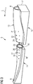
- Fig. 2 shows the blade 5.
- the blade 5 comprises an aerodynamically designed portion 7 which is shaped for optimum exploitation of the wind energy and a blade root 8 for connecting the blade 5 to the hub 6. Further, the blade 5 comprises a blade tip 9 which faces away from the blade root 8. The blade 5 extends in a longitudinal direction L which points from the blade root 8 towards the blade tip 9.
- the blade 5 has a length M which, for example, may be between 15 to 100 m or even more.
- the wind turbine blade 5 comprises a leading edge 10 and a trailing edge 11.
- Fig. 3 shows a perspective view of a blade portion 12 (also referred as first blade portion) and a blade portion 13 (also referred as second blade portion).
- the blade portion 12 comprises the blade tip 9 and the blade portion 13 comprises the blade root 8.
- the blade portion 12 comprises a connecting surface 23 and the blade portion 13 comprises a connecting surface 24.
- the blade portions 12, 13 are configured to be connected at together the connecting surfaces 23, 24.
- the connecting surfaces 23, 24 run essentially perpendicular to the longitudinal direction L.
- the blade portions 12, 13 are longitudinal segments of the blade 5 (see e.g. Fig. 2 ).
- the blade portion 12 is casted by means of a mold 14 (also referred as first mold) and the blade portion 13 is casted by means of a mold 15 (also referred as second mold).
- the mold 14 is a multi-part mold comprising a lower mold part 16 and an upper mold part (not shown).
- the upper mold part may be removed after molding the blade portion 12 as shown in Fig. 3 .
- the mold 15 is a multi-part mold comprising a lower mold part 17 and an upper mold part (not shown).
- the mold 14 comprises a hollow space 18 having a negative form of the blade portion 12.
- the mold 15 comprises a hollow space (not shown) having a negative form of the blade portion 13.
- an outer surface 19 of the blade portion 12 is exposed.
- Markers 20 also referred as first markers
- an outer surface 21 of the blade portion 13 is exposed.
- Markers 22 also referred as second markers
- the markers 20, 22 can be set when the blade portions 12, 13 lie in the molds 14, 15. Therefore, a large contact surface between the blade portions 12, 13 and the molds 14, 15 is provided. This has the advantage that the blade portions 12, 13 are substantially stressless and, thus, undeformed.
- initial positions of the markers 20, 22 may be determined, e.g. by means of measuring and recording the same. Further, target positions of the markers 20, 22 may be determined by setting a relation between the initial position of the markers 20 relative to the initial positions of the markers 22.
- the target positions are determined by means of computer generated positions.
- the initial positions can be combined with computer generated positions of the markers 20, 22 for obtaining the target positions of the markers 20, 22.
- the markers 20, 22 may be digitally generated points and/or concretely provided or created on the surface 19, 21.
- 2 - 30, 3 - 10, 3 - 7, or 4 to 5 markers 20 are provided.
- 2 - 30, 3 - 10, 3 - 7, or 4 to 5 markers 22 are provided.
- the markers 20 and/or the markers 22 may be arranged in at least two rows along the longitudinal direction L.
- Fig. 4 shows a perspective view of the blade portions 12, 13.
- the blade portions 12, 13 are carried by a carrying device 25.
- the carrying device 25 is configured to move the blade portion 12 in at least 3, 4, 5 or 6 degrees of freedom relative to the blade portion 13.
- the carrying device 25 is configured to move the blade portion 12 in longitudinal direction L and/or in height direction H and/or in side direction Y which is perpendicular to the height direction H and the longitudinal direction L.
- the carrying device 25 is configured to rotate or tilt the blade portion 12 around the longitudinal direction L and/or the height direction H and/or the side direction Y.
- the carrying device 25 may comprise a support structure 26, in particular a trolley or yoke, configured to support the blade portion 12 at one contact surface 27 and a support structure 28, in particular a trolley or yoke, configured to support the blade portion 12 at another contact surface 29.
- a support structure 26, in particular a trolley or yoke configured to support the blade portion 12 at one contact surface 27
- a support structure 28, in particular a trolley or yoke configured to support the blade portion 12 at another contact surface 29.
- more support structures 30, 31, 32, in particular trolleys or yokes are provided for supporting the blade portion 12.
- the carrying device 25 may also be configured to move the blade portion 13 in at least 3, 4, 5 or 6 degrees of freedom relative to the blade portion 12.
- the carrying device 25 is configured to move the blade portion 13 in longitudinal direction L and/or in height direction H and/or in side direction Y which is perpendicular to the height direction.
- the carrying device 25 is configured to rotate or tilt the blade portion 13 around the longitudinal direction L and/or the height direction H and/or the side direction Y.
- the carrying device 25 may comprise a support structure 33, in particular a trolley or yoke, configured to support the blade portion 13 at one contact surface 34 and a support structure 35, in particular a trolley or yoke, configured to support the blade portion 13 at another contact surface 36.
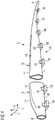
- Fig. 5 shows a perspective view of the support structure 26 of the carrying device 25.
- the support structure 26 comprises a frame 37 to which wheels 38 are connected. Further, a motor 39 may be provided for driving the support structure 26 by means of the motor 39.
- the support structure 26 is, thus, configured to move in longitudinal direction L (see e.g. Fig. 7 ) .
- the support structure 26 comprises a receptacle 40 for receiving the blade portion 12.
- the receptacle 40 interacts with the contact surface 27 of the blade portion 12 (see Fig. 4 ) by means of arc shaped surfaces 41 which are provided at, in particular movable, holding shells 42, 43.
- Each shell 42, 43 may be arc shaped.
- the holding shells 42, 43 may be arranged side by side forming a V-shape or U-shape.
- Fig. 6 shows a schematical side view of the carrying device 26.
- the support structure 26 comprise a lifting system 44, in particular a lifting platform, for lifting the receptacle 40 and the blade portion 12 (see e.g. Fig. 7 ) in height direction H.
- the lifting system 44 may comprise a hydraulic or pneumatic mechanism (not shown) or an electric motor for lifting.
- actuators 45 for adjusting a tilt angle ⁇ of each shell 42, 43 may be provided.
- the actuators 45 may be hydraulic, pneumatic or electric actuators.
- the actuators 45 and the shells 42, 43 may be comprised by a tilt system 46 for tilting and/or twisting the blade portion 12. All support structures 26, 28, 30, 31, 30, 33, 35 may be designed as described for support structure 26.
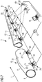
- Fig. 7 shows a perspective view of the blade portions 12, 13 when aligning the same to each other.
- the carrying device 25 comprises a control unit 47 to which all support structures 26, 28, 30, 31, 30, 33, 35 are (e.g. electrically and/or by means of communication means) connected. Further, the control unit 47 may be connected to a computer 48. Furthermore, detecting means 49 may be provide for detecting the actual positions of the markers 20, 22. This has the advantage that an exact alignment between the blade portions 12, 13 can be controlled.
- the detecting means comprise sensors and/or a cameras 50, in particular exactly two cameras 50.
- the detecting means 49 may be connected to the computer 48 and/or the control unit 47.
- digital image correlation is applied for measuring the actual positions of the markers 20, 21 and/or a movement of the markers 20, 21.
- the leading edges 10 of the blade portions 12, 13 face downward.
- the leading edges 10 of the blade portions 12, 13 may face upward.
- Fig. 8 shows a block diagram of a method for connecting two blade portions 12, 13.
- a step S1 the blade portion 12 and the blade portion 13 are provided.
- the blade portions may be provided by means of casting.
- a step S2 a plurality of markers 20 are provided on the blade portion 12 and a plurality of markers 22 are provided on the blade portion 13.
- initial positions e.g. when the blade portions lie in the molds 14, 15, see Fig. 3
- the markers 20, 22 are provided at predetermined positions at the blade portions 12, 13.
- step S4 target positions of the markers 20, 22 are determined. This can be executed by means of calculating the target positions for a connected blade 5, wherein the initial positions obtained in step S3 may be used as input values.
- step S5 detecting means 49 are provided for detecting actual positions of the markers 20, 22.
- a step S6 the blade portions 12, 13 are aligned to each other and the actual positions of the markers 20, 22 are compared with the target positions until an acceptable deviation is obtained.
- a step S7 the blade portions 12, 13 are connected together. In particular, the actual positions of the markers 20, 21 are detected by the detecting means 49 during step S7.
- Fig. 9 shows a block diagram of a method for producing a wind turbine.
- the blade 5 which is ready to mount is provided, wherein the blade 5 is provided by the method for connecting two wind turbine blade portions 12, 13 (see Fig. 8 ).
- the tower 4 is provided and sited.
- a nacelle 3 and a hub 6 are connected to the tower 4.
- a blade 5 is connected to the hub 6 of the wind turbine 1.
- Fig. 10 shows a block diagram of a method for connecting two molded portions 12, 13.
- a portion 12 is molded by means of a mold 14 and a portion 13 is molded by means of a mold 15.
- markers 20 are provided (e.g. set) on the portion 12 when the portion 12 is (e.g. lies) in the mold 14 and markers 22 are provided (e.g. set) on the portion 13 when the portion 13 is (e.g. lies) in the mold 15.
- portions 12, 13 are connected together by means of the markers 20, 22 to form a component, in particular a blade 5. Therefore, a shape accuracy of two connected portions can be improved.
Landscapes
- Engineering & Computer Science (AREA)
- Mechanical Engineering (AREA)
- Life Sciences & Earth Sciences (AREA)
- Sustainable Development (AREA)
- Sustainable Energy (AREA)
- Chemical & Material Sciences (AREA)
- Combustion & Propulsion (AREA)
- General Engineering & Computer Science (AREA)
- Power Engineering (AREA)
- Physics & Mathematics (AREA)
- Fluid Mechanics (AREA)
- Wind Motors (AREA)
Abstract
Description
- The present invention relates to a method for connecting two wind turbine blade portions, a method for producing a wind turbine, and a method for connecting two molded portions.
- Modern wind turbine rotor blades are built from fiber-reinforced plastics. A rotor blade typically comprises an airfoil having a rounded leading edge and a sharp trailing edge. The rotor blade is connected with its blade root to a hub of the wind turbine. Further, the rotor blade is connected to the hub by means of a pitch bearing that allows a pitch movement of the rotor blade. Long rotor blades experience high wind forces and are, thus, subjected to heavy loads.
- Rotor blades may be made of two half-shells connected to each other. As rotor blades become longer, it may be advantageous to manufacture a rotor blade divided into two or more segments along a longitudinal axis (i.e. longitudinal segments) of the blade. Such blade segments are also known as spanwise segments. Further, such spanwise segments may be casted individually and connected together after casting.
EP 2 432 972 B1 shows a method for assembling spanwise segments of a wind turbine blade. - Connecting such spanwise segments of a blade is a challenging task since the segments may come from different molds. It may be important that the blade tip is placed correctly with respect to the blade root and a twist of the blade is as designed and intended. If this is not the case, the loads throughout the blade may change, e.g. during energy generation. This may lead to malfunction. For example, the blade may strike the tower.
- It is one object of the present invention to provide an improved method for connecting two wind turbine blade portions.
- Accordingly, a method for connecting two wind turbine blade portions is provided. The method comprises the steps of: a) providing a first wind turbine blade portion and a second wind turbine blade portion, b) providing a plurality of first markers on the first blade portion and providing a plurality of second markers on the second blade portion, c) determining of target positions of the first markers and the second markers, d) aligning the wind turbine blade portions to each other and comparing actual positions of the first markers and the second markers with the target positions, and e) connecting the wind turbine blade portions together.
- Therefore, a shape accuracy of the wind turbine blade can be improved. For example, two, three or more blade portions can be connected together. In particular, each blade portion comprises two blade shells arranged opposite and connected to each other. Providing markers on the blade portion means that the markers are set. Setting the markers may mean that physical markers are connected to the blade portion, created on the blade portion or digital markers are allocated to the blade portion. Aligning means that one of the blade portions or both are moved until the blade portions match as intended.
- In particular, the first blade portion comprises an outer surface at which the first markers are provided. Preferably, the second blade portion comprises an outer surface at which the second markers are provided. In particular, the first markers and the second markers are arranged along a longitudinal direction of the blade. For example, at least three, four, five, six, seven, eight, nine, ten or more first markers are provided in step b). In particular, at least three, four, five, six, seven, eight, nine, ten or more second markers are provided in step b). Preferably, the wind turbine blade portions are side by side in longitudinal direction of the blade when aligned to each other.
- According to an embodiment, the first wind turbine blade portion is molded by means of a first mold and the second wind turbine blade portion is molded by means of a second mold.
- In particular, the first and the second blade portions are casted. Molding the blade by means of at least two molds has the advantage that longer blades may by manufactured. Preferably, the first mold is a multi-part, in particular two-part, mold and/or the second mold is a multi-part, in particular two-part, mold. This has the advantage that the blade portions may be accessible after molding without removing the blade portion from the lower part of the mold which carries the mold. Preferably, the first mold comprises a hollow space having a negative form of the first blade portion and/or the second mold comprises a hollow space having a negative form of the second blade portion.
- According to a further embodiment, step b) is executed when the first wind turbine blade portion is in the first mold and/or the second wind turbine blade portion is in the second mold.
- This has the advantage that the first and/or second blade portions are substantially stressless and, thus, undeformed. Preferably, step b) is executed during molding or afterwards. For example, the first blade portion lies in the first mold and/or the second blade portion lies in the second mold when step b) is executed. Therefore, a large contact surface between the respective blade portion and the respective mold is provided.
- According to a further embodiment, initial positions of the first and the second markers are determined during or immediately after step b).
- Preferably, the initial positions are measured and recorded. Thus, an ideal shape of the blade portion may be reproduced even after handling or manipulating the same.
- According to a further embodiment, the target positions of the markers are determined by means of the initial positions of the first and the second markers.
- Preferably, the initial positions of the first markers relative to each other are set as target positions of the first markers. In particular, the initial positions of the second markers relative to each other are set as target positions of the second markers.
- According to a further embodiment, the target positions of the first and the second markers are determined by setting a relation between the initial position of the first markers relative to the initial positions of the second markers.
- Alternatively or additionally, the target positions are determined by means of computer generated positions. For example, the initial positions can be combined with computer generated positions of the markers for obtaining the target positions of the first and the second markers.
- According to a further embodiment, the actual positions of the first and/or the second markers are detected by means of detecting means during step d).
- This has the advantage that an exact alignment can be controlled. Preferably, the detecting means comprise a sensor, in particular sensors, and/or a camera, in particular cameras .
- According to a further embodiment, step d) is executed by means of digital image correlation.
- Digital image correlation and tracking is an optical method that employs tracking and image registration techniques for accurate 2D and 3D measurements of changes in images. This method can be used to measure full-field displacement and strains. Compared to strain gages and extensometers, the amount of information gathered about the fine details of deformation during mechanical tests is increased due to the ability to provide e.g. both local and average data using digital image correlation. This has the advantage that a real time measurement and alignment can be executed.
- According to a further embodiment, step d) is executed by means of a carrying device which is configured to move the first wind turbine blade portion in at least 3, 4, 5 or 6 degrees of freedom relative to the second wind turbine blade portion.
- The carrying device may comprise a first support structure, in particular a first trolley or yoke, configured to support the first blade portion at one contact surface and a second support structure, in particular a second trolley or yoke, configured to support the first blade portion at another contact surface. For example, the first and the second support structures are configured to move in longitudinal direction of the blade relative to each other when supporting the first blade portion. In particular, the second blade portion is fixed.
- Preferably, the carrying device is configured to move the first blade portion in longitudinal direction of the blade and/or in height direction and/or in a side direction which is perpendicular to the longitudinal direction. Preferably, the carrying device is configured to rotate or tilt the first blade portion around the longitudinal direction and/or the height direction and/or the side direction.
- In particular, the first and the second support structures comprise a lifting system for lifting the blade portion. For example, the first and the second support structures comprise a tilt system for tilting and/or twisting the blade portion. Preferably, three, four, five, six or more support structures, in particular a trolleys or yokes, are provided for supporting the first blade portion.
- According to a further embodiment, the carrying device is configured to move the second wind turbine blade portion in at least 3, 4, 5 or 6 degrees of freedom relative to the first wind turbine blade portion.
- The carrying device may comprise a third support structure, in particular a third trolley or yoke, configured to support the second blade portion at one contact surface and a fourth support structure, in particular a fourth trolley or yoke, configured to support the second blade portion at another contact surface. For example, the third and the fourth support structures are configured to move in longitudinal direction of the blade relative to each other when supporting the second blade portion.
- In particular, the third and the fourth support structures comprise a lifting system for lifting the second blade portion. For example, the third and the fourth support structures comprise a tilt system for tilting and/or twisting the second blade portion. Preferably, three, four, five, six or more support structures, in particular trolleys or yokes, are provided for supporting the second blade portion.
- According to a further embodiment, in step d) and/or e) leading edges of the first and the second wind turbine blade portions face downward or upward.
- Thus, handling the blade portion during step d) and/or e) is improved.
- According to a further embodiment, the first and the second markers are digitally generated points and/or concretely provided on the respective wind turbine blade portion.
- Digitally generated points have the advantage that setting such points can be executed e.g. automatically. Concretely provided markers (i.e. physical markers) have the advantage that such points may be visible without equipment.
- According to a further embodiment, the first wind turbine blade portion and the second wind turbine blade portion are longitudinal segments of the wind turbine blade.
- This means, when the blade is completed, the segments are arranged one after another along the longitudinal axis of the blade. In particular, an angle between connecting surfaces of the wind turbine blade portions and a longitudinal axis of the wind turbine blade is at least 45°, in particular 90°.
- Further, a method for producing a wind turbine is provided. The method comprises the steps of: a2) connecting two wind turbine blade portions according to such a method for connecting two wind turbine blade portions such that a wind turbine blade is provided, and b2) connecting the wind turbine blade to a hub of the wind turbine.
- Therefore, a wind turbine having long wind turbine blades can be provided. Preferably, the method comprises further the steps of providing a tower, a nacelle and a hub of the wind turbine.
- Wind turbine presently refers to an apparatus converting the wind's kinetic energy into rotational energy, which may again be converted to electrical energy by the apparatus.
- Furthermore, a method for connecting two molded portions is provided. The method comprises the steps of: a3) molding a first portion by means of a first mold and a second portion by means of a second mold, b3) providing first markers on the first portion when the first portion is in the first mold and second markers on the second portion when the second portion is in the second mold, and c3) connecting the first and the second portions together by means of the first and the second markers.
- This has the advantage that the first and the second portions are substantially stressless and, thus, undeformed when providing the markers. Therefore, a shape accuracy of two connected portions can be improved. The first and the second portion may be molded by means of casting.
- Providing the markers on the first portion means that the markers are set. Preferably, the first portion lies in the first mold and/or the second portion lies in the second mold during step b3). Therefore, a large contact surface between the respective portion and the respective mold is provided. Preferably, the first and the second portions are connected to form a component. The component e.g. may be a wind turbine blade or any other component.
- Preferably, the first mold is a multi-part, in particular two-part, mold and/or the second mold is a multi-part, in particular two-part, mold. Preferably, the first mold comprises a hollow space having a negative form of the first portion and/or the second mold comprises a hollow space having a negative form of the second portion.
- The embodiments and features described with reference to the method for producing a wind turbine blade of the present invention apply mutatis mutandis to the method for connecting two molded portions of the present invention and vice versa.
- Further possible implementations or alternative solutions of the invention also encompass combinations - that are not explicitly mentioned herein - of features described above or below with regard to the embodiments. The person skilled in the art may also add individual or isolated aspects and features to the most basic form of the invention.
- Further embodiments, features and advantages of the present invention will become apparent from the subsequent description and dependent claims, taken in conjunction with the accompanying drawings, in which:
-
Fig. 1 shows a perspective view of a wind turbine according to one embodiment; -
Fig. 2 shows a perspective view of a wind turbine blade of the wind turbine according toFig. 1 ; -
Fig. 3 shows a perspective view of a first and a second wind turbine blade portion each lying in a mold; -
Fig. 4 shows a perspective view of the first and the second wind turbine blade portion carried by a carrying device; -
Fig. 5 shows a perspective view of a support structure of the carrying device; -
Fig. 6 shows a schematical side view of the support structure; -
Fig. 7 shows a perspective view of the first and the second wind turbine blade portion when aligning the same to each other; -
Fig. 8 shows a block diagram of a method for connecting two wind turbine blade portions; -
Fig. 9 shows a block diagram of a method for producing a wind turbine; and -
Fig. 10 shows a block diagram of a method for connecting two molded portions. - In the Figures, like reference numerals designate like or functionally equivalent elements, unless otherwise indicated.
-
Fig. 1 shows awind turbine 1. Thewind turbine 1 comprises a rotor 2 connected to a generator (not shown) arranged inside anacelle 3. Thenacelle 3 is arranged at an upper end of atower 4 of thewind turbine 1. - The rotor 2 comprises three blades 5 (i.e. wind turbine blades). The
blades 5 are connected to ahub 6 of thewind turbine 1. Rotors 2 of this kind may have diameters ranging from, for example, 30 to 300 meters or even more. Theblades 5 are subjected to high wind loads. At the same time, theblades 5 need to be lightweight. For these reasons,blades 5 inmodern wind turbines 1 are manufactured from fiber-reinforced composite materials, e.g. by means of casting. Of-tentimes, glass or carbon fibers in the form of unidirectional fiber mats are used.Such blades 5 may also include woods and other reinforcement materials. -
Fig. 2 shows theblade 5. Theblade 5 comprises an aerodynamically designedportion 7 which is shaped for optimum exploitation of the wind energy and ablade root 8 for connecting theblade 5 to thehub 6. Further, theblade 5 comprises ablade tip 9 which faces away from theblade root 8. Theblade 5 extends in a longitudinal direction L which points from theblade root 8 towards theblade tip 9. Theblade 5 has a length M which, for example, may be between 15 to 100 m or even more. Thewind turbine blade 5 comprises aleading edge 10 and a trailingedge 11. -
Fig. 3 shows a perspective view of a blade portion 12 (also referred as first blade portion) and a blade portion 13 (also referred as second blade portion). Theblade portion 12 comprises theblade tip 9 and theblade portion 13 comprises theblade root 8. Further, theblade portion 12 comprises a connectingsurface 23 and theblade portion 13 comprises a connectingsurface 24. Theblade portions surfaces surfaces blade portions Fig. 2 ). - The
blade portion 12 is casted by means of a mold 14 (also referred as first mold) and theblade portion 13 is casted by means of a mold 15 (also referred as second mold). Preferably, the mold 14 is a multi-part mold comprising alower mold part 16 and an upper mold part (not shown). For example, the upper mold part may be removed after molding theblade portion 12 as shown inFig. 3 . Preferably, themold 15 is a multi-part mold comprising alower mold part 17 and an upper mold part (not shown). - This has the advantage that the
blade portions blade portion lower mold part hollow space 18 having a negative form of theblade portion 12. In particular, themold 15 comprises a hollow space (not shown) having a negative form of theblade portion 13. - As shown in
Fig. 3 anouter surface 19 of theblade portion 12 is exposed. Markers 20 (also referred as first markers) are provided on thesurface 19. Further, anouter surface 21 of theblade portion 13 is exposed. Markers 22 (also referred as second markers) are provided on thesurface 21. Themarkers blade portions molds 14, 15. Therefore, a large contact surface between theblade portions molds 14, 15 is provided. This has the advantage that theblade portions - After providing the
markers markers markers markers 20 relative to the initial positions of themarkers 22. - Alternatively or additionally, the target positions are determined by means of computer generated positions. For example, the initial positions can be combined with computer generated positions of the
markers markers markers surface markers 20 are provided. For example, 2 - 30, 3 - 10, 3 - 7, or 4 to 5markers 22 are provided. Themarkers 20 and/or themarkers 22 may be arranged in at least two rows along the longitudinal direction L. -
Fig. 4 shows a perspective view of theblade portions blade portions device 25. The carryingdevice 25 is configured to move theblade portion 12 in at least 3, 4, 5 or 6 degrees of freedom relative to theblade portion 13. In particular, the carryingdevice 25 is configured to move theblade portion 12 in longitudinal direction L and/or in height direction H and/or in side direction Y which is perpendicular to the height direction H and the longitudinal direction L. Preferably, the carryingdevice 25 is configured to rotate or tilt theblade portion 12 around the longitudinal direction L and/or the height direction H and/or the side direction Y. - The carrying
device 25 may comprise asupport structure 26, in particular a trolley or yoke, configured to support theblade portion 12 at onecontact surface 27 and asupport structure 28, in particular a trolley or yoke, configured to support theblade portion 12 at anothercontact surface 29. Preferably,more support structures blade portion 12. - The carrying
device 25 may also be configured to move theblade portion 13 in at least 3, 4, 5 or 6 degrees of freedom relative to theblade portion 12. In particular, the carryingdevice 25 is configured to move theblade portion 13 in longitudinal direction L and/or in height direction H and/or in side direction Y which is perpendicular to the height direction. Preferably, the carryingdevice 25 is configured to rotate or tilt theblade portion 13 around the longitudinal direction L and/or the height direction H and/or the side direction Y. The carryingdevice 25 may comprise asupport structure 33, in particular a trolley or yoke, configured to support theblade portion 13 at onecontact surface 34 and asupport structure 35, in particular a trolley or yoke, configured to support theblade portion 13 at anothercontact surface 36. -
Fig. 5 shows a perspective view of thesupport structure 26 of the carryingdevice 25. Thesupport structure 26 comprises aframe 37 to whichwheels 38 are connected. Further, amotor 39 may be provided for driving thesupport structure 26 by means of themotor 39. Thesupport structure 26 is, thus, configured to move in longitudinal direction L (see e.g.Fig. 7 ) . - Further, the
support structure 26 comprises areceptacle 40 for receiving theblade portion 12. Thereceptacle 40 interacts with thecontact surface 27 of the blade portion 12 (seeFig. 4 ) by means of arc shaped surfaces 41 which are provided at, in particular movable, holdingshells shell shells -
Fig. 6 shows a schematical side view of the carryingdevice 26. Thesupport structure 26 comprise alifting system 44, in particular a lifting platform, for lifting thereceptacle 40 and the blade portion 12 (see e.g.Fig. 7 ) in height direction H.The lifting system 44 may comprise a hydraulic or pneumatic mechanism (not shown) or an electric motor for lifting. - For example, actuators 45 for adjusting a tilt angle α of each
shell actuators 45 may be hydraulic, pneumatic or electric actuators. Theactuators 45 and theshells tilt system 46 for tilting and/or twisting theblade portion 12. Allsupport structures support structure 26. -
Fig. 7 shows a perspective view of theblade portions device 25 comprises acontrol unit 47 to which all supportstructures control unit 47 may be connected to acomputer 48. Furthermore, detectingmeans 49 may be provide for detecting the actual positions of themarkers blade portions - Preferably, the detecting means comprise sensors and/or a
cameras 50, in particular exactly twocameras 50. The detecting means 49 may be connected to thecomputer 48 and/or thecontrol unit 47. Preferably, digital image correlation is applied for measuring the actual positions of themarkers markers Fig. 4 and7 the leadingedges 10 of theblade portions edges 10 of theblade portions support structures blade portions blade portions -
Fig. 8 shows a block diagram of a method for connecting twoblade portions blade portion 12 and theblade portion 13 are provided. The blade portions may be provided by means of casting. In a step S2 a plurality ofmarkers 20 are provided on theblade portion 12 and a plurality ofmarkers 22 are provided on theblade portion 13. In an optional step S3 initial positions (e.g. when the blade portions lie in themolds 14, 15, seeFig. 3 ) of themarkers markers blade portions - In a step S4 target positions of the
markers connected blade 5, wherein the initial positions obtained in step S3 may be used as input values. In a step S5 detecting means 49 are provided for detecting actual positions of themarkers - In a step S6 the
blade portions markers blade portions markers -
Fig. 9 shows a block diagram of a method for producing a wind turbine. In a steps S11 theblade 5 which is ready to mount is provided, wherein theblade 5 is provided by the method for connecting two windturbine blade portions 12, 13 (seeFig. 8 ). In a step S12 thetower 4 is provided and sited. In a step S13 anacelle 3 and ahub 6 are connected to thetower 4. In a step S14 ablade 5 is connected to thehub 6 of thewind turbine 1. -
Fig. 10 shows a block diagram of a method for connecting two moldedportions portion 12 is molded by means of a mold 14 and aportion 13 is molded by means of amold 15. In astep S22 markers 20 are provided (e.g. set) on theportion 12 when theportion 12 is (e.g. lies) in the mold 14 andmarkers 22 are provided (e.g. set) on theportion 13 when theportion 13 is (e.g. lies) in themold 15. In astep S23 portions markers blade 5. Therefore, a shape accuracy of two connected portions can be improved. - The features explained with reference to
Fig. 1 - 7 apply mutatis mutandis to the methods ofFig. 8 - 10 . - Although the present invention has been described in accordance with preferred embodiments, it is obvious for the person skilled in the art that modifications are possible in all embodiments.
Claims (15)
- A method for connecting two wind turbine blade portions (12, 13), the method comprising the steps of:a) providing (S1) a first wind turbine blade portion (12) and a second wind turbine blade portion (13),b) providing (S2) a plurality of first markers (20) on the first blade portion (12) and providing a plurality of second markers (22) on the second blade portion (13),c) determining (S4) of target positions of the first markers (20) and the second markers (22),d) aligning (S6) the wind turbine blade portions (12, 13) to each other and comparing actual positions of the first markers (20) and the second markers (21) with the target positions, ande) connecting (S7) the wind turbine blade portions (12, 13) together.
- The method according to claim 1,
wherein in step a) the first wind turbine blade portion (12) is molded by means of a first mold (14) and the second wind turbine blade portion (13) is molded by means of a second mold (15). - The method according to claim 2,
wherein step b) is executed when the first wind turbine blade portion (12) is in the first mold (14) and/or the second wind turbine blade portion (13) is in the second mold (15). - The method according to one of claims 1 - 3,
wherein initial positions of the first and the second markers (20, 22) are determined during or immediately after step b). - The method according to claim 4,
wherein the target positions of the first markers (20) and/or the second markers (22) are determined by means of the initial positions of the first markers (20) and/or the second markers (22). - The method according to claim 5,
wherein the target positions of the first markers (20) and the second markers (22) are determined by setting a relation between the initial position of the first markers (20) relative to the initial positions of the second markers (22). - The method according to one of claims 1 - 6,
wherein the actual positions of the first and/or the second markers (20, 22) are detected during step d) by means of detecting means (49). - The method according to one of claims 1 - 7,
wherein step d) is executed by means of digital image correlation. - The method according to one of claims 1 - 8,
wherein step d) is executed by means of a carrying device (25) which is configured to move the first wind turbine blade portion (12) in at least 3, 4, 5 or 6 degrees of freedom relative to the second wind turbine blade portion (13). - The method according to claim 9,
wherein the carrying device (25) is configured to move the second wind turbine blade portion (13) in at least 3, 4, 5 or 6 degrees of freedom relative to the first wind turbine blade portion (12). - The method according to one of claims 1 - 10,
wherein in step d) and/or e) leading edges (10) of the first and the second wind turbine blade portions (12, 13) face downward or upward. - The method according to one of claims 1 - 11,
wherein the first and the second markers (20, 22) are digitally generated points and/or concretely created on the respective wind turbine blade portion (12, 13). - The method according to one of claims 1 - 12,
wherein the first wind turbine blade portion (12) and the second wind turbine blade portion (13) are longitudinal segments of a wind turbine blade (5). - A method for producing a wind turbine (1), the method comprising the steps of:a2) connecting (S11) two wind turbine blade portions (12, 13) according to the method of one of claims 1 - 13 such that a wind turbine blade (5) is provided, andb2) connecting (S14) the wind turbine blade (5) to a hub (6) of the wind turbine (1).
- A method for connecting two molded portions (12, 13), the method comprising the steps of:a3) molding (S21) a first portion (12) by means of a first mold (14) and a second portion (13) by means of a second mold (15),b3) providing (S22) first markers (20) on the first portion (12) when the first portion (12) is in the first mold (14) and second markers (22) on the second portion (13) when the second portion (13) is in the second mold (15), andc3) connecting (S23) the first and the second portions (12, 13) together by means of the first and the second markers (20, 21) .
Priority Applications (6)
| Application Number | Priority Date | Filing Date | Title |
|---|---|---|---|
| EP19185181.5A EP3763938B1 (en) | 2019-07-09 | 2019-07-09 | Method for connecting two wind turbine blade portions, method for producing a wind turbine, and method for connecting two molded portions |
| DK19185181.5T DK3763938T3 (en) | 2019-07-09 | 2019-07-09 | METHOD OF ASSEMBLING TWO WIND TURBINE ROTOR BLADE PARTS, METHOD OF MANUFACTURE OF A WIND TURBINE AND METHOD OF ASSEMBLING TWO MOLDED PARTS |
| PL19185181.5T PL3763938T3 (en) | 2019-07-09 | 2019-07-09 | Method for connecting two wind turbine blade portions, method for producing a wind turbine, and method for connecting two molded portions |
| US16/916,479 US12297801B2 (en) | 2019-07-09 | 2020-06-30 | Method for connecting two wind turbine blade portions, method for producing a wind turbine, and method for connecting two molded portions |
| TW109122738A TWI758769B (en) | 2019-07-09 | 2020-07-06 | Method for connecting two wind turbine blade portions, method for producing a wind turbine, and method for connecting two molded portions |
| CN202010656806.1A CN112211777B (en) | 2019-07-09 | 2020-07-09 | Method for connecting two wind turbine blade sections, manufacturing a wind turbine and connecting two moulded sections |
Applications Claiming Priority (1)
| Application Number | Priority Date | Filing Date | Title |
|---|---|---|---|
| EP19185181.5A EP3763938B1 (en) | 2019-07-09 | 2019-07-09 | Method for connecting two wind turbine blade portions, method for producing a wind turbine, and method for connecting two molded portions |
Publications (2)
| Publication Number | Publication Date |
|---|---|
| EP3763938A1 true EP3763938A1 (en) | 2021-01-13 |
| EP3763938B1 EP3763938B1 (en) | 2024-09-11 |
Family
ID=67220715
Family Applications (1)
| Application Number | Title | Priority Date | Filing Date |
|---|---|---|---|
| EP19185181.5A Active EP3763938B1 (en) | 2019-07-09 | 2019-07-09 | Method for connecting two wind turbine blade portions, method for producing a wind turbine, and method for connecting two molded portions |
Country Status (6)
| Country | Link |
|---|---|
| US (1) | US12297801B2 (en) |
| EP (1) | EP3763938B1 (en) |
| CN (1) | CN112211777B (en) |
| DK (1) | DK3763938T3 (en) |
| PL (1) | PL3763938T3 (en) |
| TW (1) | TWI758769B (en) |
Cited By (1)
| Publication number | Priority date | Publication date | Assignee | Title |
|---|---|---|---|---|
| EP4066987A1 (en) * | 2021-04-01 | 2022-10-05 | Siemens Gamesa Renewable Energy A/S | Method for manufacturing a wind turbine blade |
Families Citing this family (3)
| Publication number | Priority date | Publication date | Assignee | Title |
|---|---|---|---|---|
| EP3808543A1 (en) * | 2019-10-18 | 2021-04-21 | Siemens Gamesa Renewable Energy A/S | A method and a system for assembling blade parts of a wind turbine blade |
| CN117072372B (en) * | 2023-08-30 | 2025-12-19 | 中电投张北风力发电有限公司 | Wind power blade vortex generator installation auxiliary tool and application method thereof |
| EP4563813A1 (en) * | 2023-11-30 | 2025-06-04 | LM Wind Power A/S | A blade handling assembly for moving a wind turbine blade between different locations |
Citations (6)
| Publication number | Priority date | Publication date | Assignee | Title |
|---|---|---|---|---|
| EP2075467A2 (en) * | 2007-12-28 | 2009-07-01 | General Electric Company | Integrated shipping fixture and assembly method for jointed wind turbine blades |
| EP2432972A1 (en) | 2009-05-22 | 2012-03-28 | Modular Wind Energy, Inc. | Systems and methods for transporting and assembling segmented wind turbine blades |
| US20170043542A1 (en) * | 2014-04-24 | 2017-02-16 | Lm Wp Patent Holding A/S | A Wind Turbine Blade Manufacturing System and Method |
| WO2018091735A1 (en) * | 2016-11-21 | 2018-05-24 | Lm Wind Power International Technology Ii Aps | A method and system for establishing a sectional or modular wind turbine blade and a mobile factory for joining sections of a wind turbine blade |
| US20180178216A1 (en) * | 2013-03-14 | 2018-06-28 | STRATEC CONSUMABLES GmbH | Method for manufacturing a microfluidic device |
| WO2018215457A1 (en) * | 2017-05-22 | 2018-11-29 | Lm Wind Power International Technology Ii Aps | Wind turbine blade and method of assembly of blade elements to form a wind turbine blade |
Family Cites Families (10)
| Publication number | Priority date | Publication date | Assignee | Title |
|---|---|---|---|---|
| ES2584939T3 (en) * | 2009-09-29 | 2016-09-30 | Vestas Wind Systems A/S | Mold for the manufacture of wind turbine blades |
| RU94936U1 (en) * | 2010-02-04 | 2010-06-10 | Открытое Акционерное Общество "Российские Железные Дороги" | SYSTEM OF CONTROL OF DEFORMATION OF RAIL LASHES OF CANDLESS RAILWAY |
| DE102010002230B4 (en) * | 2010-02-23 | 2014-11-27 | Senvion Se | Method and device for attaching a reference mark on a rotor blade for a wind turbine |
| DK2481559T3 (en) * | 2011-02-01 | 2019-07-29 | Siemens Gamesa Renewable Energy As | Preparing a wind turbine blade for proper positioning in a subsequent assembly step |
| CN102629700A (en) | 2012-04-28 | 2012-08-08 | 无锡合志科技有限公司 | Universal battery structure adopting lithium battery material |
| KR101358230B1 (en) * | 2012-06-28 | 2014-02-05 | 삼성중공업 주식회사 | Blade installing apparatus and method of installing blade using thereof for wind turbine |
| CN107443883A (en) | 2013-02-25 | 2017-12-08 | 斯克林集团公司 | Alignment device and alignment methods |
| JP6234074B2 (en) * | 2013-06-07 | 2017-11-22 | オリンパス株式会社 | Semiconductor device, solid-state imaging device, and imaging device |
| US10668673B2 (en) * | 2015-05-18 | 2020-06-02 | Flightware, Inc. | Systems and methods for automated composite layup quality assurance |
| DE102016123188A1 (en) * | 2016-12-01 | 2018-06-07 | Dr. Ing. H.C. F. Porsche Aktiengesellschaft | Adjustable loading robot |
-
2019
- 2019-07-09 PL PL19185181.5T patent/PL3763938T3/en unknown
- 2019-07-09 DK DK19185181.5T patent/DK3763938T3/en active
- 2019-07-09 EP EP19185181.5A patent/EP3763938B1/en active Active
-
2020
- 2020-06-30 US US16/916,479 patent/US12297801B2/en active Active
- 2020-07-06 TW TW109122738A patent/TWI758769B/en active
- 2020-07-09 CN CN202010656806.1A patent/CN112211777B/en active Active
Patent Citations (6)
| Publication number | Priority date | Publication date | Assignee | Title |
|---|---|---|---|---|
| EP2075467A2 (en) * | 2007-12-28 | 2009-07-01 | General Electric Company | Integrated shipping fixture and assembly method for jointed wind turbine blades |
| EP2432972A1 (en) | 2009-05-22 | 2012-03-28 | Modular Wind Energy, Inc. | Systems and methods for transporting and assembling segmented wind turbine blades |
| US20180178216A1 (en) * | 2013-03-14 | 2018-06-28 | STRATEC CONSUMABLES GmbH | Method for manufacturing a microfluidic device |
| US20170043542A1 (en) * | 2014-04-24 | 2017-02-16 | Lm Wp Patent Holding A/S | A Wind Turbine Blade Manufacturing System and Method |
| WO2018091735A1 (en) * | 2016-11-21 | 2018-05-24 | Lm Wind Power International Technology Ii Aps | A method and system for establishing a sectional or modular wind turbine blade and a mobile factory for joining sections of a wind turbine blade |
| WO2018215457A1 (en) * | 2017-05-22 | 2018-11-29 | Lm Wind Power International Technology Ii Aps | Wind turbine blade and method of assembly of blade elements to form a wind turbine blade |
Cited By (4)
| Publication number | Priority date | Publication date | Assignee | Title |
|---|---|---|---|---|
| EP4066987A1 (en) * | 2021-04-01 | 2022-10-05 | Siemens Gamesa Renewable Energy A/S | Method for manufacturing a wind turbine blade |
| WO2022207246A1 (en) * | 2021-04-01 | 2022-10-06 | Siemens Gamesa Renewable Energy A/S | Method for manufacturing a wind turbine blade |
| CN117413122A (en) * | 2021-04-01 | 2024-01-16 | 西门子歌美飒可再生能源公司 | Method for manufacturing wind turbine blades |
| US12420366B2 (en) | 2021-04-01 | 2025-09-23 | Siemens Gamesa Renewable Energy A/S | Method for manufacturing a wind turbine blade |
Also Published As
| Publication number | Publication date |
|---|---|
| CN112211777A (en) | 2021-01-12 |
| US12297801B2 (en) | 2025-05-13 |
| CN112211777B (en) | 2025-09-16 |
| TWI758769B (en) | 2022-03-21 |
| DK3763938T3 (en) | 2024-11-04 |
| PL3763938T3 (en) | 2024-12-09 |
| EP3763938B1 (en) | 2024-09-11 |
| US20210010460A1 (en) | 2021-01-14 |
| TW202113226A (en) | 2021-04-01 |
Similar Documents
| Publication | Publication Date | Title |
|---|---|---|
| US12297801B2 (en) | Method for connecting two wind turbine blade portions, method for producing a wind turbine, and method for connecting two molded portions | |
| CN101868620B (en) | Method and system for measuring deflection of a hollow component of a wind energy system from a normal position | |
| US8171809B2 (en) | System and method for wind turbine inspection | |
| DK1906192T3 (en) | Apparatus for evaluating sensors and / or for controlling the operation of an apparatus which includes a sensor | |
| JP4959814B2 (en) | Load measuring device, method and program | |
| Lundstrom et al. | Monitoring the dynamics of a helicopter main rotor with high-speed stereophotogrammetry | |
| CN112219029B (en) | Sensor device for wind turbines | |
| CN112796957A (en) | A kind of detection method and device and equipment of fan blade | |
| JP2018145898A (en) | Wind power blade or wind power generator | |
| WO2011134473A1 (en) | A method and system for detecting angular deflection in a wind turbine blade or component | |
| CN115243855A (en) | Rotational system for wind turbine blade components | |
| EP3468759A1 (en) | Blade mould for manufacturing a blade shell part of a wind turbine blade and related method | |
| EP1508691A1 (en) | Horizontal axis wind turbine and method for measuring upflow angle | |
| WO2017110743A1 (en) | Large structure maintenance method, method for maintaining wind-power generation facility, and unmanned aircraft | |
| CN119895144A (en) | Computer-implemented method and device for aligning a blade load measurement system of a rotor blade of a wind power installation, wind power installation having at least one rotor blade with a strain sensor, and computer-readable storage medium | |
| EP1947329A1 (en) | Wind turbine and method for mitigating the asymmetric loads endured by the rotor or the wind turbine | |
| US7966865B2 (en) | Method for balancing radical projections detached from a rotating assembly | |
| AU2009340218A1 (en) | Load measuring apparatus, method, and program | |
| CN112955310A (en) | Detection system, method and detection device thereof | |
| EP3259472B1 (en) | Control for a wind turbine | |
| US10598608B2 (en) | Method of inspecting interior of wind turbine blade and inspection device for wind turbine blade | |
| CN117433695B (en) | Calibration method for blade load of wind driven generator | |
| EP4563813A1 (en) | A blade handling assembly for moving a wind turbine blade between different locations | |
| TWI818472B (en) | Method for manufacturing a wind turbine blade | |
| CN113795373A (en) | Manufacturing a wind turbine blade shell part |
Legal Events
| Date | Code | Title | Description |
|---|---|---|---|
| PUAI | Public reference made under article 153(3) epc to a published international application that has entered the european phase |
Free format text: ORIGINAL CODE: 0009012 |
|
| STAA | Information on the status of an ep patent application or granted ep patent |
Free format text: STATUS: THE APPLICATION HAS BEEN PUBLISHED |
|
| AK | Designated contracting states |
Kind code of ref document: A1 Designated state(s): AL AT BE BG CH CY CZ DE DK EE ES FI FR GB GR HR HU IE IS IT LI LT LU LV MC MK MT NL NO PL PT RO RS SE SI SK SM TR |
|
| STAA | Information on the status of an ep patent application or granted ep patent |
Free format text: STATUS: REQUEST FOR EXAMINATION WAS MADE |
|
| 17P | Request for examination filed |
Effective date: 20210713 |
|
| RBV | Designated contracting states (corrected) |
Designated state(s): AL AT BE BG CH CY CZ DE DK EE ES FI FR GB GR HR HU IE IS IT LI LT LU LV MC MK MT NL NO PL PT RO RS SE SI SK SM TR |
|
| STAA | Information on the status of an ep patent application or granted ep patent |
Free format text: STATUS: EXAMINATION IS IN PROGRESS |
|
| 17Q | First examination report despatched |
Effective date: 20220921 |
|
| GRAP | Despatch of communication of intention to grant a patent |
Free format text: ORIGINAL CODE: EPIDOSNIGR1 |
|
| STAA | Information on the status of an ep patent application or granted ep patent |
Free format text: STATUS: GRANT OF PATENT IS INTENDED |
|
| RIC1 | Information provided on ipc code assigned before grant |
Ipc: B29L 31/08 20060101ALI20240313BHEP Ipc: B29C 65/00 20060101ALI20240313BHEP Ipc: B29C 65/78 20060101ALI20240313BHEP Ipc: F03D 1/06 20060101AFI20240313BHEP |
|
| INTG | Intention to grant announced |
Effective date: 20240328 |
|
| RIN1 | Information on inventor provided before grant (corrected) |
Inventor name: NIELSEN, MOGENS Inventor name: HENRICHSEN, SOEREN RANDRUP DAUGAARD |
|
| GRAS | Grant fee paid |
Free format text: ORIGINAL CODE: EPIDOSNIGR3 |
|
| GRAA | (expected) grant |
Free format text: ORIGINAL CODE: 0009210 |
|
| STAA | Information on the status of an ep patent application or granted ep patent |
Free format text: STATUS: THE PATENT HAS BEEN GRANTED |
|
| AK | Designated contracting states |
Kind code of ref document: B1 Designated state(s): AL AT BE BG CH CY CZ DE DK EE ES FI FR GB GR HR HU IE IS IT LI LT LU LV MC MK MT NL NO PL PT RO RS SE SI SK SM TR |
|
| REG | Reference to a national code |
Ref country code: GB Ref legal event code: FG4D |
|
| REG | Reference to a national code |
Ref country code: CH Ref legal event code: EP |
|
| REG | Reference to a national code |
Ref country code: DE Ref legal event code: R096 Ref document number: 602019058603 Country of ref document: DE |
|
| REG | Reference to a national code |
Ref country code: IE Ref legal event code: FG4D |
|
| REG | Reference to a national code |
Ref country code: DK Ref legal event code: T3 Effective date: 20241029 |
|
| REG | Reference to a national code |
Ref country code: NL Ref legal event code: FP |
|
| REG | Reference to a national code |
Ref country code: LT Ref legal event code: MG9D |
|
| PG25 | Lapsed in a contracting state [announced via postgrant information from national office to epo] |
Ref country code: NO Free format text: LAPSE BECAUSE OF FAILURE TO SUBMIT A TRANSLATION OF THE DESCRIPTION OR TO PAY THE FEE WITHIN THE PRESCRIBED TIME-LIMIT Effective date: 20241211 |
|
| PG25 | Lapsed in a contracting state [announced via postgrant information from national office to epo] |
Ref country code: GR Free format text: LAPSE BECAUSE OF FAILURE TO SUBMIT A TRANSLATION OF THE DESCRIPTION OR TO PAY THE FEE WITHIN THE PRESCRIBED TIME-LIMIT Effective date: 20241212 Ref country code: FI Free format text: LAPSE BECAUSE OF FAILURE TO SUBMIT A TRANSLATION OF THE DESCRIPTION OR TO PAY THE FEE WITHIN THE PRESCRIBED TIME-LIMIT Effective date: 20240911 |
|
| PG25 | Lapsed in a contracting state [announced via postgrant information from national office to epo] |
Ref country code: BG Free format text: LAPSE BECAUSE OF FAILURE TO SUBMIT A TRANSLATION OF THE DESCRIPTION OR TO PAY THE FEE WITHIN THE PRESCRIBED TIME-LIMIT Effective date: 20240911 |
|
| PG25 | Lapsed in a contracting state [announced via postgrant information from national office to epo] |
Ref country code: LV Free format text: LAPSE BECAUSE OF FAILURE TO SUBMIT A TRANSLATION OF THE DESCRIPTION OR TO PAY THE FEE WITHIN THE PRESCRIBED TIME-LIMIT Effective date: 20240911 |
|
| PG25 | Lapsed in a contracting state [announced via postgrant information from national office to epo] |
Ref country code: HR Free format text: LAPSE BECAUSE OF FAILURE TO SUBMIT A TRANSLATION OF THE DESCRIPTION OR TO PAY THE FEE WITHIN THE PRESCRIBED TIME-LIMIT Effective date: 20240911 |
|
| PG25 | Lapsed in a contracting state [announced via postgrant information from national office to epo] |
Ref country code: RS Free format text: LAPSE BECAUSE OF FAILURE TO SUBMIT A TRANSLATION OF THE DESCRIPTION OR TO PAY THE FEE WITHIN THE PRESCRIBED TIME-LIMIT Effective date: 20241211 Ref country code: ES Free format text: LAPSE BECAUSE OF FAILURE TO SUBMIT A TRANSLATION OF THE DESCRIPTION OR TO PAY THE FEE WITHIN THE PRESCRIBED TIME-LIMIT Effective date: 20240911 |
|
| PG25 | Lapsed in a contracting state [announced via postgrant information from national office to epo] |
Ref country code: RS Free format text: LAPSE BECAUSE OF FAILURE TO SUBMIT A TRANSLATION OF THE DESCRIPTION OR TO PAY THE FEE WITHIN THE PRESCRIBED TIME-LIMIT Effective date: 20241211 Ref country code: NO Free format text: LAPSE BECAUSE OF FAILURE TO SUBMIT A TRANSLATION OF THE DESCRIPTION OR TO PAY THE FEE WITHIN THE PRESCRIBED TIME-LIMIT Effective date: 20241211 Ref country code: LV Free format text: LAPSE BECAUSE OF FAILURE TO SUBMIT A TRANSLATION OF THE DESCRIPTION OR TO PAY THE FEE WITHIN THE PRESCRIBED TIME-LIMIT Effective date: 20240911 Ref country code: HR Free format text: LAPSE BECAUSE OF FAILURE TO SUBMIT A TRANSLATION OF THE DESCRIPTION OR TO PAY THE FEE WITHIN THE PRESCRIBED TIME-LIMIT Effective date: 20240911 Ref country code: GR Free format text: LAPSE BECAUSE OF FAILURE TO SUBMIT A TRANSLATION OF THE DESCRIPTION OR TO PAY THE FEE WITHIN THE PRESCRIBED TIME-LIMIT Effective date: 20241212 Ref country code: FI Free format text: LAPSE BECAUSE OF FAILURE TO SUBMIT A TRANSLATION OF THE DESCRIPTION OR TO PAY THE FEE WITHIN THE PRESCRIBED TIME-LIMIT Effective date: 20240911 Ref country code: ES Free format text: LAPSE BECAUSE OF FAILURE TO SUBMIT A TRANSLATION OF THE DESCRIPTION OR TO PAY THE FEE WITHIN THE PRESCRIBED TIME-LIMIT Effective date: 20240911 Ref country code: BG Free format text: LAPSE BECAUSE OF FAILURE TO SUBMIT A TRANSLATION OF THE DESCRIPTION OR TO PAY THE FEE WITHIN THE PRESCRIBED TIME-LIMIT Effective date: 20240911 |
|
| REG | Reference to a national code |
Ref country code: AT Ref legal event code: MK05 Ref document number: 1722882 Country of ref document: AT Kind code of ref document: T Effective date: 20240911 |
|
| PG25 | Lapsed in a contracting state [announced via postgrant information from national office to epo] |
Ref country code: IS Free format text: LAPSE BECAUSE OF FAILURE TO SUBMIT A TRANSLATION OF THE DESCRIPTION OR TO PAY THE FEE WITHIN THE PRESCRIBED TIME-LIMIT Effective date: 20250111 Ref country code: PT Free format text: LAPSE BECAUSE OF FAILURE TO SUBMIT A TRANSLATION OF THE DESCRIPTION OR TO PAY THE FEE WITHIN THE PRESCRIBED TIME-LIMIT Effective date: 20250113 |
|
| PG25 | Lapsed in a contracting state [announced via postgrant information from national office to epo] |
Ref country code: RO Free format text: LAPSE BECAUSE OF FAILURE TO SUBMIT A TRANSLATION OF THE DESCRIPTION OR TO PAY THE FEE WITHIN THE PRESCRIBED TIME-LIMIT Effective date: 20240911 Ref country code: SM Free format text: LAPSE BECAUSE OF FAILURE TO SUBMIT A TRANSLATION OF THE DESCRIPTION OR TO PAY THE FEE WITHIN THE PRESCRIBED TIME-LIMIT Effective date: 20240911 |
|
| PG25 | Lapsed in a contracting state [announced via postgrant information from national office to epo] |
Ref country code: EE Free format text: LAPSE BECAUSE OF FAILURE TO SUBMIT A TRANSLATION OF THE DESCRIPTION OR TO PAY THE FEE WITHIN THE PRESCRIBED TIME-LIMIT Effective date: 20240911 Ref country code: AT Free format text: LAPSE BECAUSE OF FAILURE TO SUBMIT A TRANSLATION OF THE DESCRIPTION OR TO PAY THE FEE WITHIN THE PRESCRIBED TIME-LIMIT Effective date: 20240911 |
|
| PG25 | Lapsed in a contracting state [announced via postgrant information from national office to epo] |
Ref country code: CZ Free format text: LAPSE BECAUSE OF FAILURE TO SUBMIT A TRANSLATION OF THE DESCRIPTION OR TO PAY THE FEE WITHIN THE PRESCRIBED TIME-LIMIT Effective date: 20240911 |
|
| PG25 | Lapsed in a contracting state [announced via postgrant information from national office to epo] |
Ref country code: IT Free format text: LAPSE BECAUSE OF FAILURE TO SUBMIT A TRANSLATION OF THE DESCRIPTION OR TO PAY THE FEE WITHIN THE PRESCRIBED TIME-LIMIT Effective date: 20240911 Ref country code: SK Free format text: LAPSE BECAUSE OF FAILURE TO SUBMIT A TRANSLATION OF THE DESCRIPTION OR TO PAY THE FEE WITHIN THE PRESCRIBED TIME-LIMIT Effective date: 20240911 |
|
| REG | Reference to a national code |
Ref country code: DE Ref legal event code: R097 Ref document number: 602019058603 Country of ref document: DE |
|
| PLBE | No opposition filed within time limit |
Free format text: ORIGINAL CODE: 0009261 |
|
| STAA | Information on the status of an ep patent application or granted ep patent |
Free format text: STATUS: NO OPPOSITION FILED WITHIN TIME LIMIT |
|
| PGFP | Annual fee paid to national office [announced via postgrant information from national office to epo] |
Ref country code: NL Payment date: 20250724 Year of fee payment: 7 |
|
| 26N | No opposition filed |
Effective date: 20250612 |
|
| PG25 | Lapsed in a contracting state [announced via postgrant information from national office to epo] |
Ref country code: SE Free format text: LAPSE BECAUSE OF FAILURE TO SUBMIT A TRANSLATION OF THE DESCRIPTION OR TO PAY THE FEE WITHIN THE PRESCRIBED TIME-LIMIT Effective date: 20240911 |
|
| PGFP | Annual fee paid to national office [announced via postgrant information from national office to epo] |
Ref country code: DE Payment date: 20250728 Year of fee payment: 7 Ref country code: DK Payment date: 20250725 Year of fee payment: 7 |
|
| PGFP | Annual fee paid to national office [announced via postgrant information from national office to epo] |
Ref country code: GB Payment date: 20250722 Year of fee payment: 7 |
|
| PGFP | Annual fee paid to national office [announced via postgrant information from national office to epo] |
Ref country code: FR Payment date: 20250725 Year of fee payment: 7 |
|
| PGFP | Annual fee paid to national office [announced via postgrant information from national office to epo] |
Ref country code: PL Payment date: 20250616 Year of fee payment: 7 |
|
| REG | Reference to a national code |
Ref country code: CH Ref legal event code: H13 Free format text: ST27 STATUS EVENT CODE: U-0-0-H10-H13 (AS PROVIDED BY THE NATIONAL OFFICE) Effective date: 20260224 |
|
| PG25 | Lapsed in a contracting state [announced via postgrant information from national office to epo] |
Ref country code: LU Free format text: LAPSE BECAUSE OF NON-PAYMENT OF DUE FEES Effective date: 20250709 |
|
| REG | Reference to a national code |
Ref country code: BE Ref legal event code: MM Effective date: 20250731 |
|
| PG25 | Lapsed in a contracting state [announced via postgrant information from national office to epo] |
Ref country code: BE Free format text: LAPSE BECAUSE OF NON-PAYMENT OF DUE FEES Effective date: 20250731 |
|
| PG25 | Lapsed in a contracting state [announced via postgrant information from national office to epo] |
Ref country code: CH Free format text: LAPSE BECAUSE OF NON-PAYMENT OF DUE FEES Effective date: 20250731 |