EP3763919B1 - Continuous variable valve opening duration apparatus and engine provided with the same - Google Patents
Continuous variable valve opening duration apparatus and engine provided with the same Download PDFInfo
- Publication number
- EP3763919B1 EP3763919B1 EP19212321.4A EP19212321A EP3763919B1 EP 3763919 B1 EP3763919 B1 EP 3763919B1 EP 19212321 A EP19212321 A EP 19212321A EP 3763919 B1 EP3763919 B1 EP 3763919B1
- Authority
- EP
- European Patent Office
- Prior art keywords
- wheel
- cam
- variable valve
- continuous variable
- camshaft
- Prior art date
- Legal status (The legal status is an assumption and is not a legal conclusion. Google has not performed a legal analysis and makes no representation as to the accuracy of the status listed.)
- Active
Links
Images


Classifications
-
- F—MECHANICAL ENGINEERING; LIGHTING; HEATING; WEAPONS; BLASTING
- F01—MACHINES OR ENGINES IN GENERAL; ENGINE PLANTS IN GENERAL; STEAM ENGINES
- F01L—CYCLICALLY OPERATING VALVES FOR MACHINES OR ENGINES
- F01L13/00—Modifications of valve-gear to facilitate reversing, braking, starting, changing compression ratio, or other specific operations
-
- F—MECHANICAL ENGINEERING; LIGHTING; HEATING; WEAPONS; BLASTING
- F01—MACHINES OR ENGINES IN GENERAL; ENGINE PLANTS IN GENERAL; STEAM ENGINES
- F01L—CYCLICALLY OPERATING VALVES FOR MACHINES OR ENGINES
- F01L1/00—Valve-gear or valve arrangements, e.g. lift-valve gear
- F01L1/02—Valve drive
- F01L1/04—Valve drive by means of cams, camshafts, cam discs, eccentrics or the like
- F01L1/047—Camshafts
- F01L1/053—Camshafts overhead type
- F01L1/0532—Camshafts overhead type the cams being directly in contact with the driven valve
-
- F—MECHANICAL ENGINEERING; LIGHTING; HEATING; WEAPONS; BLASTING
- F01—MACHINES OR ENGINES IN GENERAL; ENGINE PLANTS IN GENERAL; STEAM ENGINES
- F01L—CYCLICALLY OPERATING VALVES FOR MACHINES OR ENGINES
- F01L1/00—Valve-gear or valve arrangements, e.g. lift-valve gear
- F01L1/26—Valve-gear or valve arrangements, e.g. lift-valve gear characterised by the provision of two or more valves operated simultaneously by same transmitting-gear; peculiar to machines or engines with more than two lift-valves per cylinder
-
- F—MECHANICAL ENGINEERING; LIGHTING; HEATING; WEAPONS; BLASTING
- F01—MACHINES OR ENGINES IN GENERAL; ENGINE PLANTS IN GENERAL; STEAM ENGINES
- F01L—CYCLICALLY OPERATING VALVES FOR MACHINES OR ENGINES
- F01L1/00—Valve-gear or valve arrangements, e.g. lift-valve gear
- F01L1/34—Valve-gear or valve arrangements, e.g. lift-valve gear characterised by the provision of means for changing the timing of the valves without changing the duration of opening and without affecting the magnitude of the valve lift
- F01L1/344—Valve-gear or valve arrangements, e.g. lift-valve gear characterised by the provision of means for changing the timing of the valves without changing the duration of opening and without affecting the magnitude of the valve lift changing the angular relationship between crankshaft and camshaft, e.g. using helicoidal gear
- F01L1/352—Valve-gear or valve arrangements, e.g. lift-valve gear characterised by the provision of means for changing the timing of the valves without changing the duration of opening and without affecting the magnitude of the valve lift changing the angular relationship between crankshaft and camshaft, e.g. using helicoidal gear using bevel or epicyclic gear
-
- F—MECHANICAL ENGINEERING; LIGHTING; HEATING; WEAPONS; BLASTING
- F01—MACHINES OR ENGINES IN GENERAL; ENGINE PLANTS IN GENERAL; STEAM ENGINES
- F01L—CYCLICALLY OPERATING VALVES FOR MACHINES OR ENGINES
- F01L1/00—Valve-gear or valve arrangements, e.g. lift-valve gear
- F01L1/02—Valve drive
- F01L1/04—Valve drive by means of cams, camshafts, cam discs, eccentrics or the like
- F01L1/047—Camshafts
- F01L1/053—Camshafts overhead type
-
- F—MECHANICAL ENGINEERING; LIGHTING; HEATING; WEAPONS; BLASTING
- F01—MACHINES OR ENGINES IN GENERAL; ENGINE PLANTS IN GENERAL; STEAM ENGINES
- F01L—CYCLICALLY OPERATING VALVES FOR MACHINES OR ENGINES
- F01L13/00—Modifications of valve-gear to facilitate reversing, braking, starting, changing compression ratio, or other specific operations
- F01L13/0015—Modifications of valve-gear to facilitate reversing, braking, starting, changing compression ratio, or other specific operations for optimising engine performances by modifying valve lift according to various working parameters, e.g. rotational speed, load, torque
-
- F—MECHANICAL ENGINEERING; LIGHTING; HEATING; WEAPONS; BLASTING
- F01—MACHINES OR ENGINES IN GENERAL; ENGINE PLANTS IN GENERAL; STEAM ENGINES
- F01M—LUBRICATING OF MACHINES OR ENGINES IN GENERAL; LUBRICATING INTERNAL COMBUSTION ENGINES; CRANKCASE VENTILATING
- F01M1/00—Pressure lubrication
- F01M1/06—Lubricating systems characterised by the provision therein of crankshafts or connecting rods with lubricant passageways, e.g. bores
-
- F—MECHANICAL ENGINEERING; LIGHTING; HEATING; WEAPONS; BLASTING
- F01—MACHINES OR ENGINES IN GENERAL; ENGINE PLANTS IN GENERAL; STEAM ENGINES
- F01L—CYCLICALLY OPERATING VALVES FOR MACHINES OR ENGINES
- F01L1/00—Valve-gear or valve arrangements, e.g. lift-valve gear
- F01L1/02—Valve drive
- F01L1/04—Valve drive by means of cams, camshafts, cam discs, eccentrics or the like
- F01L1/047—Camshafts
- F01L2001/0476—Camshaft bearings
-
- F—MECHANICAL ENGINEERING; LIGHTING; HEATING; WEAPONS; BLASTING
- F01—MACHINES OR ENGINES IN GENERAL; ENGINE PLANTS IN GENERAL; STEAM ENGINES
- F01L—CYCLICALLY OPERATING VALVES FOR MACHINES OR ENGINES
- F01L1/00—Valve-gear or valve arrangements, e.g. lift-valve gear
- F01L1/02—Valve drive
- F01L1/04—Valve drive by means of cams, camshafts, cam discs, eccentrics or the like
- F01L1/047—Camshafts
- F01L1/053—Camshafts overhead type
- F01L2001/0537—Double overhead camshafts [DOHC]
-
- F—MECHANICAL ENGINEERING; LIGHTING; HEATING; WEAPONS; BLASTING
- F01—MACHINES OR ENGINES IN GENERAL; ENGINE PLANTS IN GENERAL; STEAM ENGINES
- F01L—CYCLICALLY OPERATING VALVES FOR MACHINES OR ENGINES
- F01L13/00—Modifications of valve-gear to facilitate reversing, braking, starting, changing compression ratio, or other specific operations
- F01L2013/10—Auxiliary actuators for variable valve timing
- F01L2013/103—Electric motors
-
- F—MECHANICAL ENGINEERING; LIGHTING; HEATING; WEAPONS; BLASTING
- F01—MACHINES OR ENGINES IN GENERAL; ENGINE PLANTS IN GENERAL; STEAM ENGINES
- F01L—CYCLICALLY OPERATING VALVES FOR MACHINES OR ENGINES
- F01L2250/00—Camshaft drives characterised by their transmission means
- F01L2250/06—Camshaft drives characterised by their transmission means the camshaft being driven by gear wheels
-
- F—MECHANICAL ENGINEERING; LIGHTING; HEATING; WEAPONS; BLASTING
- F01—MACHINES OR ENGINES IN GENERAL; ENGINE PLANTS IN GENERAL; STEAM ENGINES
- F01L—CYCLICALLY OPERATING VALVES FOR MACHINES OR ENGINES
- F01L2305/00—Valve arrangements comprising rollers
-
- F—MECHANICAL ENGINEERING; LIGHTING; HEATING; WEAPONS; BLASTING
- F01—MACHINES OR ENGINES IN GENERAL; ENGINE PLANTS IN GENERAL; STEAM ENGINES
- F01L—CYCLICALLY OPERATING VALVES FOR MACHINES OR ENGINES
- F01L2810/00—Arrangements solving specific problems in relation with valve gears
- F01L2810/02—Lubrication
-
- F—MECHANICAL ENGINEERING; LIGHTING; HEATING; WEAPONS; BLASTING
- F01—MACHINES OR ENGINES IN GENERAL; ENGINE PLANTS IN GENERAL; STEAM ENGINES
- F01L—CYCLICALLY OPERATING VALVES FOR MACHINES OR ENGINES
- F01L2810/00—Arrangements solving specific problems in relation with valve gears
- F01L2810/03—Reducing vibration
-
- F—MECHANICAL ENGINEERING; LIGHTING; HEATING; WEAPONS; BLASTING
- F01—MACHINES OR ENGINES IN GENERAL; ENGINE PLANTS IN GENERAL; STEAM ENGINES
- F01L—CYCLICALLY OPERATING VALVES FOR MACHINES OR ENGINES
- F01L2810/00—Arrangements solving specific problems in relation with valve gears
- F01L2810/04—Reducing noise
-
- F—MECHANICAL ENGINEERING; LIGHTING; HEATING; WEAPONS; BLASTING
- F01—MACHINES OR ENGINES IN GENERAL; ENGINE PLANTS IN GENERAL; STEAM ENGINES
- F01M—LUBRICATING OF MACHINES OR ENGINES IN GENERAL; LUBRICATING INTERNAL COMBUSTION ENGINES; CRANKCASE VENTILATING
- F01M1/00—Pressure lubrication
- F01M1/06—Lubricating systems characterised by the provision therein of crankshafts or connecting rods with lubricant passageways, e.g. bores
- F01M2001/064—Camshaft with passageways
-
- F—MECHANICAL ENGINEERING; LIGHTING; HEATING; WEAPONS; BLASTING
- F02—COMBUSTION ENGINES; HOT-GAS OR COMBUSTION-PRODUCT ENGINE PLANTS
- F02D—CONTROLLING COMBUSTION ENGINES
- F02D13/00—Controlling the engine output power by varying inlet or exhaust valve operating characteristics, e.g. timing
- F02D13/02—Controlling the engine output power by varying inlet or exhaust valve operating characteristics, e.g. timing during engine operation
- F02D13/0203—Variable control of intake and exhaust valves
- F02D13/0215—Variable control of intake and exhaust valves changing the valve timing only
Definitions
- the present disclosure relates to a continuous variable valve duration apparatus and an engine provided with the same.
- An internal combustion engine generates power by burning fuel in a combustion chamber in an air media drawn into the chamber.
- Intake valves are operated by a camshaft in order to intake the air, and the air is drawn into the combustion chamber while the intake valves are open.
- exhaust valves are operated by the camshaft, and a combustion gas is exhausted from the combustion chamber while the exhaust valves are open.
- Optimal operation of the intake valves and the exhaust valves depends on a rotation speed of the engine.
- an optimal lift or optimal opening/closing timing of the valves depends on the rotation speed of the engine.
- various researches such as designing of a plurality of cams and a continuous variable valve lift (CVVL) that can change valve lift depending on engine speed, have been undertaken.
- CVVL continuous variable valve lift
- Patent Literature EP 3 486 441 A1 provides continuous variable valve duration apparatus including: a camshaft; a cam unit on which a cam is formed, and the camshaft inserted to the cam; an inner wheel for transmitting rotation of the camshaft to the cam unit; a wheel housing into which the inner wheel is rotatably inserted and movable perpendicular to the camshaft; a guide shaft on which a guide screw thread is formed and disposed perpendicular to the camshaft; a worm wheel formed with an inner screw thread for engaging with the guide screw thread, and the worm wheel disposed within the wheel housing; and a control shaft on which a control worm for engaging with the worm wheel is formed.
- Various aspects of the present invention are directly providing a continuous variable valve duration apparatus and an engine provided with the same which may vary opening duration of a valve based on operation conditions of an engine and reduce noise and vibration.
- a continuous variable valve duration apparatus includes a camshaft, a cam unit on which a cam is formed, and the camshaft inserted into the cam, a guide shaft on which a guide screw thread is formed and disposed perpendicular to the camshaft, a guide bracket on which the guide shaft is mounted, an inner wheel configured to transmit rotation of the camshaft to the cam unit, a wheel housing into which the inner wheel is rotatably inserted and movable perpendicular to the camshaft such that, when a relative position of the wheel housing with respect to the camshaft is changed, a relative rotation speed of the cam with respect to a rotation speed of the camshaft is changed, and the wheel housing disposed within the guide bracket, a worm wheel to which an inner screw thread configured to engage with the guide screw thread is formed therewithin, and to which an outer screw thread is formed thereon, and the worm wheel disposed within the wheel housing, a control shaft on which a control worm configured to engage with the
- the wheel elastic portion may be a double torsion spring.
- a spring seating portion to which the double torsion spring is mounted may be formed to the worm wheel
- the double torsion spring may include a spring body winding on the spring seating portion and first and second support portions for elastically supporting the spring body, and first and second spring insert portions into which the first and second support portions are inserted may be formed inside the guide bracket.
- An insertion hole into which the guide shaft is inserted and a moving space within which the wheel housing is movable may be formed to the guide bracket.
- the continuous variable valve duration apparatus may further include two guide walls protruded from the wheel housing, and a moving hole formed in each of the two guide walls and the guide shaft configured to insert into the moving holes.
- the worm wheel may be disposed between the guide walls and configured to selectively push one of the two guide walls to move the wheel housing.
- the continuous variable valve duration apparatus may further include a sliding shaft fixed to the guide bracket configured to guide movement of the wheel housing, and a sliding hole formed in the wheel housing, and the sliding shaft configured to insert to the wheel housing.
- the continuous variable valve duration apparatus may further include a worm shaft cap fixed to the guide bracket configured to support the control shaft.
- the continuous variable valve duration apparatus may further include a first sliding hole and a second sliding hole respectively formed to the inner wheel, a cam slot formed to the cam unit, a roller wheel connected to the camshaft and rotatably inserted into the first sliding hole, and a roller cam slidably inserted into the cam slot and rotatably inserted into the second sliding hole.
- the roller cam may include a roller cam body slidably inserted into the cam slot, a cam head rotatably inserted into the second sliding hole, and a protrusion configured to inhibit the roller cam from being removed.
- the roller wheel may include a wheel body slidably connected to the camshaft, and a wheel head rotatably inserted into the first sliding hole.
- the continuous variable valve duration apparatus may further include a camshaft oil hole formed within the camshaft along a longitudinal direction thereof, a body oil hole formed to the wheel body of the roller wheel and configured to communicate with the camshaft oil hole, and an oil groove formed to the wheel head of the roller wheel and configured to communicate with the body oil hole.
- the cam unit may include a first cam portion and a second cam portion which are disposed corresponding to a cylinder and an adjacent cylinder respectively, and the inner wheel may include a first inner wheel and a second inner wheel configured to transmit the rotation of the camshaft to the first cam portion and the second cam portion respectively.
- the first inner wheel and the second inner wheel may be connected rotatable to each other.
- the continuous variable valve duration apparatus may further include a bearing disposed within the wheel housing and configured to support the first inner wheel and the second inner wheel.
- the continuous variable valve duration apparatus may further include two cams formed in the first cam portion and the second cam portion respectively, a cam connecting portion formed between the two cams, and a cam cap on which a cam supporting portion configured to support the cam connecting portion is formed.
- An engine according to an embodiment of the present invention may be provided with the continuous variable valve duration apparatus.
- a continuous variable valve duration apparatus may vary an opening duration of a valve depending on operation conditions of an engine, with a simple construction.
- the continuous variable valve duration apparatus may be reduced in size and thus the entire height of a valve train may be reduced.
- the continuous variable valve duration apparatus may be applied to an existing engine without excessive modification, thus productivity may be enhance and production cost may be reduced.
- the continuous variable valve duration apparatus can reduce noise and vibration by applying a wheel elastic portion even if there is a production error in the parts.
- CVVT continuously variable valve timing
- FIG. 1 is a perspective view of an engine provided with a continuous variable valve duration apparatus according to an embodiment of the present invention
- FIG. 2 is a side view of a continuous variable valve duration apparatus according to an embodiment of the present invention.
- FIG. 3 is an exploded perspective view of a continuous variable valve duration apparatus according to an embodiment of the present invention
- FIG. 4 is a partial perspective view of a continuous variable valve duration apparatus according to an embodiment of the present invention.
- FIG. 5 is a partial exploded perspective view of a continuous variable valve duration apparatus according to an embodiment of the present invention and FIG. 6 is a cross-sectional view along line VI-VI of FIG. 4 .
- an engine 1 includes a continuous variable valve duration apparatus.
- 4 cylinders 211, 212, 213 and 214 are formed to the engine, but it is not limited thereto.
- a continuous variable valve duration apparatus may include a camshaft 30, a cam unit 70 on which a cam 71 is formed, and the camshaft 30 inserted into the cam71 , a guide shaft 132 on which a guide screw thread 130 is formed and disposed perpendicular to the camshaft 30, a guide bracket 134 on which the guide shaft 132 is mounted, an inner wheel 80 configured to transmit rotation of the camshaft 30 to the cam unit 70, a wheel housing 90 into which the inner wheel 80 is rotatably inserted and movable perpendicular to the camshaft 30, and the wheel housing 90 disposed within the guide bracket 134, a worm wheel 50 to which an inner screw thread 52 configured to engage with the guide screw thread 130 is formed therewithin, and to which an outer screw thread 54 is formed thereon, and the worm wheel 50 disposed within the wheel housing 90, a control shaft 102 on which a control worm 104 configured to engage with the outer screw thread 54 is formed, and an wheel elastic portion 150 (referring to FIG.
- the camshaft 30 may be an intake camshaft or an exhaust camshaft.
- An insertion hole 137 into which the guide shaft 132 is inserted and a moving space 138 within which the wheel housing 90 is movable may be formed to the guide bracket 134.
- the continuous variable valve duration apparatus may further include two guide walls 92 protruded from the wheel housing 90, and a moving hole 94 formed in each of the two guide walls 92 and the guide shaft 132 configured to insert into the moving holes 94.
- the worm wheel 50 may be disposed between the guide walls 92 and configured to selectively push one of the two guide walls 92 to move the wheel housing 90.
- the continuous variable valve duration apparatus further includes a sliding shaft 135 fixed to the guide bracket 134 through a sliding shaft hole 135c configured for guiding movement of the wheel housing 90 and a sliding hole 96 into which the sliding shaft 135 is inserted is formed to the wheel housing 90.
- the continuous variable valve duration apparatus further includes a worm shaft cap 139 fixed to the guide bracket 134 configured for supporting the control shaft 102.
- the worm shaft cap 139 may be fixed to the guide bracket 134 through bolts 136.
- Connecting scheme of the guide bracket 134, the wheel housing 90 and the worm wheel 50 may simply and minimize layout of the continuous variable valve duration apparatus.
- a connecting hole 132b is formed in the guide shaft 132 so that the guide shaft 132 can be coupled to the guide bracket 134 through a connecting pin 132a.
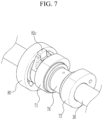
- FIG. 7 is a perspective view showing an inner wheel and a cam unit applicable to an embodiment of the present invention
- FIG. 8 is an exploded perspective view showing an inner wheel and a cam unit applicable to an embodiment of the present invention.
- a first sliding hole 86 and a second sliding hole 88 are formed the inner wheel 80 respectively and a cam slot 74 is formed to the cam unit 70.
- the continuous variable valve duration apparatus further includes a roller wheel 60 connected to the camshaft 30 and rotatably inserted into the first sliding hole 86 and a roller cam 82 slidably inserted into the cam slot 74 and rotatably inserted into the second sliding hole 88.
- the roller cam 82 includes a roller cam body 82a slidably inserted into the cam slot 74 and a cam head 82b rotatably inserted into the second sliding hole 88.
- a protrusion 82c is formed at the roller cam 82 for preventing the roller cam 82 from being separated from the inner wheel 80 along the longitudinal direction of the camshaft 30.
- the roller wheel 60 includes a wheel body 62 slidably connected to the camshaft 30 and a wheel head 64 rotatably inserted into the first sliding hole 86 and the wheel body 62 and the wheel head 64 may be integrally formed.
- a camshaft hole 34 is formed to the camshaft 30, the wheel body 62 of the roller wheel 60 is movably inserted into the camshaft hole 34 and the wheel head 64 is rotatably inserted into the first sliding hole 86.
- a camshaft oil hole 32 is formed within the camshaft 30 along a longitudinal direction thereof, a body oil hole 66 communicated with the camshaft oil hole 32 is formed to the wheel body 62 of the roller wheel 60 and an oil groove 68 (referring to Fig. 16 ) communicated with the body oil hole 66 is formed to the wheel head 64 of the roller wheel 60.
- Lubricant supplied to the camshaft oil hole 32 may be supplied to the inner wheel 80 through the body oil hole 66, the communicate hole 69 and the oil groove 68.
- FIG. 9 is a perspective view showing mounting a wheel elastic portion according to an embodiment of the present invention
- FIG. 10 is a perspective view showing a wheel elastic portion and a worm wheel applicable to an embodiment of the present invention.
- FIG. 11 is a cross-sectional view along line XI-XI of FIG. 5 and FIG. 12 is a cross-sectional view along line XII-XII of FIG. 5 .
- the wheel elastic portion 150 may be a double torsion spring and a spring seating portion 56 to which the double torsion spring 150 is mounted is formed to the worm wheel 50.
- the double torsion spring 150 may include a spring body 152 winding on the spring seating portion 56 and first and second support portions 154 and 456 for elastically supporting the spring body 152, and first and second spring insert portions 134a and 134b into which the first and second support portions 154 and 156 are inserted may be formed inside the guide bracket 134.
- tolerances are required for the operation of each component of a continuous variable valve duration apparatus, but vibration and noise may occur during engine operation due to tolerances among the control worm 104, the worm wheel 50 and the guide screw thread 130.
- the double torsion spring 150 may be configured to push the worm wheel 50 to the guide shaft 132 and the control shaft 102 to suppress vibration and noise generation during engine operation, with or without tolerances.
- FIG. 13 and FIG. 14 are drawings showing an inner wheel of a continuous variable valve duration apparatus according to an embodiment of the present invention.
- the cam unit 70 includes a first cam portion 70a and a second cam portion 70b which are disposed corresponding to a cylinder and an adjacent cylinder respectively, for example the first cylinder 201 and the adjacent second cylinder 202 and the inner wheel 80 includes a first inner wheel 80a and a second inner wheel 80b transmitting rotation of the camshaft 30 to the first cam portion 70a and the second cam portion 70b respectively.
- the continuous variable valve duration apparatus further includes a bearing 140 disposed within the wheel housing 90 for supporting the first inner wheel 80a and the second inner wheel 80b.
- the bearing 140 may be a needle bearing, the first and the second inner wheels 80a and 80b are disposed within one wheel housing 90 and the bearing 140 may rotatably support the first and the second inner wheels 80a and 80b.
- first and the second inner wheels 80a and 80b may be disposed within one wheel housing 90, element numbers may be reduced, so that productivity and manufacturing economy may be enhanced.
- the first inner wheel 80a and the second inner wheel 80b within the wheel housing 90 may be connected rotatable to each other.
- a first inner wheel connecting portion 84 and a second inner wheel connecting portion 85 are formed to the first inner wheel 80a and the second inner wheel 80b respectively, and the first inner wheel connecting portion 84 and the second inner wheel connecting portion 85 are connected to each other.
- first inner wheel connecting portion 84 and the second inner wheel connecting portion 85 are formed as convex and concave, it is not limited thereto.
- the first inner wheel 80a and the second inner wheel 80b are connected rotatable to each other with variable connecting structures.
- Two cams 71 and 72 may be formed on the first and the second cam portions 70a and 70b as a pair and a cam cap connecting portion 76 is formed between the paired cams 71 and 72 of each of the first and second cam portions 70a and 70b.
- the cam 71 and 72 rotate and open the valve 200.
- the continuously variable valve duration apparatus further includes a cam cap 40 on which a cam supporting portion 46 configured to rotatably support the cam cap connecting portion 76 is formed on the cam cap 40.
- FIG. 15A and FIG. 15B are drawings showing an operation of worm wheel and a wheel housing according to an embodiment of the present invention
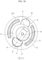
- FIG. 16 to FIG. 18 are drawings showing operations of an inner wheel of a continuous variable valve duration apparatus according to an embodiment of the present invention.
- an ECU engine control unit or electric control unit transmits control signals to the control portion 100, and then the control motor 106 rotates the control shaft 102.
- control worm 104 engaged with the outer screw thread 54 rotates the worm wheel 50. And since the inner screw thread 52 formed to the worm wheel 50 is engaged with the guide screw thread 130 and thus the worm wheel 50 moves along the guide screw thread 130.
- the worm wheel 50 moves along the guide shaft 132 depending on the rotation of the control shaft 102 and the worm wheel 50 selectively pushes one of the two guide walls 92, and thus a relative position of the wheel housing 90 with respect to the camshaft 30 is changed.
- FIG. 19A and FIG. 19B are drawings showing a cam slot of a continuous variable valve duration apparatus according to an embodiment of the present invention
- FIG. 20A , FIG. 20B and FIG. 20C are graphs showing valve profile of a continuous variable valve duration apparatus according to an embodiment of the present invention.
- the cam slot 74 may be formed more retarded than a position of the cam 71 or 72 (referring to 74a of FIG. 19A ) or the cam slot 74 may be formed more advanced than a position of the cam 71 or 72 (referring to 74b of FIG. 19B ), or the cam slot 74 may be formed with the same phase of the cam 71 or 72.
- various valve profiles may be achieved.
- valve 200 Although maximum lift of the valve 200 is constant, however rotation speed of the cam 71 and 72 with respect to the rotation speed of the camshaft 30 is changed depending on relative positions of the slider housing 90 so that closing and opening time of the valve 200 is changed. In an implementation, duration of the valve 200 is changed.
- opening and closing time of the valve may be simultaneously changed as shown in FIG. 20A .
- closing time of the valve 200 may be retarded or advanced as shown FIG. 20B .
- opening time of the valve 200 may be retarded or advanced as shown FIG. 20C .
- a continuous variable valve duration apparatus may achieve various valve duration with a simple construction.
- the continuous variable valve duration apparatus may be reduced in size and thus the entire height of a valve train may be reduced.
- the continuous variable valve duration apparatus may be applied to an existing engine without excessive modification, thus productivity may be enhance and production cost may be reduced.
- the continuous variable valve duration apparatus can reduce noise and vibration by applying a wheel elastic portion even if there is a production error in the parts.
Landscapes
- Engineering & Computer Science (AREA)
- Mechanical Engineering (AREA)
- General Engineering & Computer Science (AREA)
- Valve Device For Special Equipments (AREA)
Description
- This application claims priority to and the benefit of
Korean Patent Application No. 10-2019-0084343 filed in the Korean Intellectual Property Office on July 12, 2019 - The present disclosure relates to a continuous variable valve duration apparatus and an engine provided with the same.
- An internal combustion engine generates power by burning fuel in a combustion chamber in an air media drawn into the chamber. Intake valves are operated by a camshaft in order to intake the air, and the air is drawn into the combustion chamber while the intake valves are open. In addition, exhaust valves are operated by the camshaft, and a combustion gas is exhausted from the combustion chamber while the exhaust valves are open.
- Optimal operation of the intake valves and the exhaust valves depends on a rotation speed of the engine. For example, an optimal lift or optimal opening/closing timing of the valves depends on the rotation speed of the engine. In order to achieve such optimal valve operation depending on the rotation speed of the engine, various researches, such as designing of a plurality of cams and a continuous variable valve lift (CVVL) that can change valve lift depending on engine speed, have been undertaken.
- The disclosure of this section is to provide background information relating to the invention.
- Patent Literature
EP 3 486 441 A1 provides continuous variable valve duration apparatus including: a camshaft; a cam unit on which a cam is formed, and the camshaft inserted to the cam; an inner wheel for transmitting rotation of the camshaft to the cam unit; a wheel housing into which the inner wheel is rotatably inserted and movable perpendicular to the camshaft; a guide shaft on which a guide screw thread is formed and disposed perpendicular to the camshaft; a worm wheel formed with an inner screw thread for engaging with the guide screw thread, and the worm wheel disposed within the wheel housing; and a control shaft on which a control worm for engaging with the worm wheel is formed. - Various aspects of the present invention are directly providing a continuous variable valve duration apparatus and an engine provided with the same which may vary opening duration of a valve based on operation conditions of an engine and reduce noise and vibration.
- According to the present invention, a continuous variable valve duration apparatus, as defined by
independent claim 1, includes a camshaft, a cam unit on which a cam is formed, and the camshaft inserted into the cam, a guide shaft on which a guide screw thread is formed and disposed perpendicular to the camshaft, a guide bracket on which the guide shaft is mounted, an inner wheel configured to transmit rotation of the camshaft to the cam unit, a wheel housing into which the inner wheel is rotatably inserted and movable perpendicular to the camshaft such that, when a relative position of the wheel housing with respect to the camshaft is changed, a relative rotation speed of the cam with respect to a rotation speed of the camshaft is changed, and the wheel housing disposed within the guide bracket, a worm wheel to which an inner screw thread configured to engage with the guide screw thread is formed therewithin, and to which an outer screw thread is formed thereon, and the worm wheel disposed within the wheel housing, a control shaft on which a control worm configured to engage with the outer screw thread is formed, and an wheel elastic portion providing elastic force to the worm wheel to bring the worm wheel into close contact with the guide shaft and the control shaft. - The wheel elastic portion may be a double torsion spring.
- A spring seating portion to which the double torsion spring is mounted may be formed to the worm wheel
The double torsion spring may include a spring body winding on the spring seating portion and first and second support portions for elastically supporting the spring body, and first and second spring insert portions into which the first and second support portions are inserted may be formed inside the guide bracket. - An insertion hole into which the guide shaft is inserted and a moving space within which the wheel housing is movable may be formed to the guide bracket.
- The continuous variable valve duration apparatus may further include two guide walls protruded from the wheel housing, and a moving hole formed in each of the two guide walls and the guide shaft configured to insert into the moving holes.
- The worm wheel may be disposed between the guide walls and configured to selectively push one of the two guide walls to move the wheel housing.
- The continuous variable valve duration apparatus may further include a sliding shaft fixed to the guide bracket configured to guide movement of the wheel housing, and a sliding hole formed in the wheel housing, and the sliding shaft configured to insert to the wheel housing.
- The continuous variable valve duration apparatus may further include a worm shaft cap fixed to the guide bracket configured to support the control shaft.
- The continuous variable valve duration apparatus may further include a first sliding hole and a second sliding hole respectively formed to the inner wheel, a cam slot formed to the cam unit, a roller wheel connected to the camshaft and rotatably inserted into the first sliding hole, and a roller cam slidably inserted into the cam slot and rotatably inserted into the second sliding hole.
- The roller cam may include a roller cam body slidably inserted into the cam slot, a cam head rotatably inserted into the second sliding hole, and a protrusion configured to inhibit the roller cam from being removed.
- The roller wheel may include a wheel body slidably connected to the camshaft, and a wheel head rotatably inserted into the first sliding hole.
- The continuous variable valve duration apparatus may further include a camshaft oil hole formed within the camshaft along a longitudinal direction thereof, a body oil hole formed to the wheel body of the roller wheel and configured to communicate with the camshaft oil hole, and an oil groove formed to the wheel head of the roller wheel and configured to communicate with the body oil hole.
- The cam unit may include a first cam portion and a second cam portion which are disposed corresponding to a cylinder and an adjacent cylinder respectively, and the inner wheel may include a first inner wheel and a second inner wheel configured to transmit the rotation of the camshaft to the first cam portion and the second cam portion respectively.
- The first inner wheel and the second inner wheel may be connected rotatable to each other.
- The continuous variable valve duration apparatus may further include a bearing disposed within the wheel housing and configured to support the first inner wheel and the second inner wheel.
- The continuous variable valve duration apparatus may further include two cams formed in the first cam portion and the second cam portion respectively, a cam connecting portion formed between the two cams, and a cam cap on which a cam supporting portion configured to support the cam connecting portion is formed.
- An engine according to an embodiment of the present invention may be provided with the continuous variable valve duration apparatus.
- As described above, a continuous variable valve duration apparatus according to an embodiment of the present invention may vary an opening duration of a valve depending on operation conditions of an engine, with a simple construction.
- The continuous variable valve duration apparatus according to an embodiment of the present invention may be reduced in size and thus the entire height of a valve train may be reduced.
- Since the continuous variable valve duration apparatus may be applied to an existing engine without excessive modification, thus productivity may be enhance and production cost may be reduced.
- The continuous variable valve duration apparatus according to an embodiment of the present invention can reduce noise and vibration by applying a wheel elastic portion even if there is a production error in the parts.
-
-
FIG. 1 is a perspective view of an engine provided with a continuous variable valve duration apparatus according to an embodiment of the present invention. -
FIG. 2 is a side view of a continuous variable valve duration apparatus according to an embodiment of the present invention. -
FIG. 3 is an exploded perspective view of a continuous variable valve duration apparatus according to an embodiment of the present invention. -
FIG. 4 is a partial perspective view of a continuous variable valve duration apparatus according to an embodiment of the present invention. -
FIG. 5 is a partial exploded perspective view of a continuous variable valve duration apparatus according to an embodiment of the present invention. -
FIG. 6 is a cross-sectional view along line VI-VI ofFIG. 4 . -
FIG. 7 is a perspective view showing an inner wheel and a cam unit applicable to an embodiment of the present invention. -
FIG. 8 is an exploded perspective view showing an inner wheel and a cam unit applicable to an embodiment of the present invention. -
FIG. 9 is a perspective view showing mounting a wheel elastic portion according to an embodiment of the present invention. -
FIG. 10 is a perspective view showing a wheel elastic portion and a worm wheel applicable to an embodiment of the present invention. -
FIG. 11 is a cross-sectional view along line XI-XI ofFIG. 5 . -
FIG. 12 is a cross-sectional view along line XII-XII ofFIG. 5 . -
FIG. 13 andFIG. 14 are drawings showing an inner wheel of a continuous variable valve duration apparatus according to an embodiment of the present invention. -
FIG. 15A andFIG. 15B are drawings showing an operation of worm wheel and a wheel housing according to an embodiment of the present invention. -
FIG. 16 to FIG. 18 are drawings showing operations of an inner wheel of a continuous variable valve duration apparatus according to an embodiment of the present invention. -
FIG. 19A andFIG. 19B are drawings showing a cam slot of a continuous variable valve duration apparatus according to an embodiment of the present invention. -
FIG. 20A ,FIG. 20B andFIG. 20C are graphs showing valve profile of a continuous variable valve duration apparatus according to an embodiment of the present invention. -
1: engine 30: camshaft 32: camshaft oil hole 34: camshaft hole 40: cam cap 50: worm wheel 52: inner screw thread 54: outer screw thread 56: spring seating portion 60: roller wheel 62: wheel body 64: wheel head 66: body oil hole 68: oil groove 69: communicate hole 70: cam unit 70a, 70b: first/ second cam portion 71, 72: cam 74: cam slot 76: cam connecting portion 80: inner wheel 82: roller cam 82a: roller cam body 82b: roller cam head 82c: protrusion 83: cam slot 84: first inner wheel connecting portion 85: second inner wheel connecting portion 86: first sliding hole 88: second sliding hole 90: wheel housing 92: guide wall 94: moving hole 96: sliding hole 100: controller 102: control shaft 104: control worm 106: control motor 130: guide screw thread 132: guide shaft 132a: connecting pin 132b: connecting hole 134: guide bracket 134a: first spring insert portion 134b: second spring insert portion 135: sliding shaft 135a: sliding shaft hole 136: bolt 137: insertion hole 138: moving space 139: worm shaft cap 140: bearing 150: wheel elastic portion 152: spring body 154: first support portion 156: second support portion 200: valve 201-204: first -4 cylinder - In the following detailed description, only certain embodiments of the present invention have been shown and described, simply by way of illustration.
- As those skilled in the art would realize, the described embodiments may be modified in various different ways, all without departing from the scope of the present invention
- A part irrelevant to the description will be omitted to clearly describe the present invention, and the same or similar elements will be designated by the same reference numerals throughout the specification.
- In the drawings, the thickness of layers, films, panels, regions, etc., are exaggerated for clarity.
- Throughout the specification and the claims, unless explicitly described to the contrary, the word "comprise" and variations such as "comprises" or "comprising", will be understood to imply the inclusion of stated elements but not the exclusion of any other elements.
- An embodiment of the present invention will hereinafter be described in detail with reference to the accompanying drawings.
- In some implementations, in order to achieve such an optimal valve operation depending on the rotation speed of the engine, research is being conducted on a continuously variable valve timing (CVVT) apparatus that enables different valve timing operations depending on the engine speed. The CVVT may change valve timing with a fixed valve opening duration.
-
FIG. 1 is a perspective view of an engine provided with a continuous variable valve duration apparatus according to an embodiment of the present invention andFIG. 2 is a side view of a continuous variable valve duration apparatus according to an embodiment of the present invention. -
FIG. 3 is an exploded perspective view of a continuous variable valve duration apparatus according to an embodiment of the present invention andFIG. 4 is a partial perspective view of a continuous variable valve duration apparatus according to an embodiment of the present invention. -
FIG. 5 is a partial exploded perspective view of a continuous variable valve duration apparatus according to an embodiment of the present invention andFIG. 6 is a cross-sectional view along line VI-VI ofFIG. 4 . - Referring to
FIG. 1 to FIG. 6 , in embodiments, anengine 1 according to an embodiment of the present invention includes a continuous variable valve duration apparatus. - In the drawings, 4 cylinders 211, 212, 213 and 214 are formed to the engine, but it is not limited thereto.
- A continuous variable valve duration apparatus according to an embodiment of the present invention may include a
camshaft 30, acam unit 70 on which acam 71 is formed, and thecamshaft 30 inserted into the cam71 , aguide shaft 132 on which aguide screw thread 130 is formed and disposed perpendicular to thecamshaft 30, aguide bracket 134 on which theguide shaft 132 is mounted, aninner wheel 80 configured to transmit rotation of thecamshaft 30 to thecam unit 70, awheel housing 90 into which theinner wheel 80 is rotatably inserted and movable perpendicular to thecamshaft 30, and thewheel housing 90 disposed within theguide bracket 134, aworm wheel 50 to which aninner screw thread 52 configured to engage with theguide screw thread 130 is formed therewithin, and to which anouter screw thread 54 is formed thereon, and theworm wheel 50 disposed within thewheel housing 90, acontrol shaft 102 on which acontrol worm 104 configured to engage with theouter screw thread 54 is formed, and an wheel elastic portion 150 (referring toFIG. 9 ) providing elastic force to theworm wheel 50 to bring theworm wheel 50 into close contact with theguide shaft 132 and thecontrol shaft 102. - The
camshaft 30 may be an intake camshaft or an exhaust camshaft. - An
insertion hole 137 into which theguide shaft 132 is inserted and a movingspace 138 within which thewheel housing 90 is movable may be formed to theguide bracket 134. - The continuous variable valve duration apparatus may further include two
guide walls 92 protruded from thewheel housing 90, and a movinghole 94 formed in each of the twoguide walls 92 and theguide shaft 132 configured to insert into the moving holes 94. - The
worm wheel 50 may be disposed between theguide walls 92 and configured to selectively push one of the twoguide walls 92 to move thewheel housing 90. - The continuous variable valve duration apparatus further includes a sliding
shaft 135 fixed to theguide bracket 134 through a sliding shaft hole 135c configured for guiding movement of thewheel housing 90 and a slidinghole 96 into which the slidingshaft 135 is inserted is formed to thewheel housing 90. - The continuous variable valve duration apparatus further includes a
worm shaft cap 139 fixed to theguide bracket 134 configured for supporting thecontrol shaft 102. Theworm shaft cap 139 may be fixed to theguide bracket 134 throughbolts 136. - Connecting scheme of the
guide bracket 134, thewheel housing 90 and theworm wheel 50 may simply and minimize layout of the continuous variable valve duration apparatus. - A connecting
hole 132b is formed in theguide shaft 132 so that theguide shaft 132 can be coupled to theguide bracket 134 through a connectingpin 132a. -
FIG. 7 is a perspective view showing an inner wheel and a cam unit applicable to an embodiment of the present invention andFIG. 8 is an exploded perspective view showing an inner wheel and a cam unit applicable to an embodiment of the present invention. - Referring to
FIG. 1 to FIG. 8 , a first slidinghole 86 and a second slidinghole 88 are formed theinner wheel 80 respectively and acam slot 74 is formed to thecam unit 70. - The continuous variable valve duration apparatus further includes a
roller wheel 60 connected to thecamshaft 30 and rotatably inserted into the first slidinghole 86 and aroller cam 82 slidably inserted into thecam slot 74 and rotatably inserted into the second slidinghole 88. - The
roller cam 82 includes aroller cam body 82a slidably inserted into thecam slot 74 and acam head 82b rotatably inserted into the second slidinghole 88. - A
protrusion 82c is formed at theroller cam 82 for preventing theroller cam 82 from being separated from theinner wheel 80 along the longitudinal direction of thecamshaft 30. - The
roller wheel 60 includes awheel body 62 slidably connected to thecamshaft 30 and awheel head 64 rotatably inserted into the first slidinghole 86 and thewheel body 62 and thewheel head 64 may be integrally formed. - A
camshaft hole 34 is formed to thecamshaft 30, thewheel body 62 of theroller wheel 60 is movably inserted into thecamshaft hole 34 and thewheel head 64 is rotatably inserted into the first slidinghole 86. - A
camshaft oil hole 32 is formed within thecamshaft 30 along a longitudinal direction thereof, abody oil hole 66 communicated with thecamshaft oil hole 32 is formed to thewheel body 62 of theroller wheel 60 and an oil groove 68 (referring toFig. 16 ) communicated with thebody oil hole 66 is formed to thewheel head 64 of theroller wheel 60. - Lubricant supplied to the
camshaft oil hole 32 may be supplied to theinner wheel 80 through thebody oil hole 66, the communicatehole 69 and theoil groove 68. -
FIG. 9 is a perspective view showing mounting a wheel elastic portion according to an embodiment of the present invention andFIG. 10 is a perspective view showing a wheel elastic portion and a worm wheel applicable to an embodiment of the present invention. -
FIG. 11 is a cross-sectional view along line XI-XI ofFIG. 5 andFIG. 12 is a cross-sectional view along line XII-XII ofFIG. 5 . - Referring to
FIG. 9 to FIG. 12 , the wheelelastic portion 150 may be a double torsion spring and aspring seating portion 56 to which thedouble torsion spring 150 is mounted is formed to theworm wheel 50. - The
double torsion spring 150 may include aspring body 152 winding on thespring seating portion 56 and first andsecond support portions 154 and 456 for elastically supporting thespring body 152, and first and secondspring insert portions second support portions guide bracket 134. - In embodiments, tolerances are required for the operation of each component of a continuous variable valve duration apparatus, but vibration and noise may occur during engine operation due to tolerances among the
control worm 104, theworm wheel 50 and theguide screw thread 130. - Since the
double torsion spring 150 may be configured to push theworm wheel 50 to theguide shaft 132 and thecontrol shaft 102 to suppress vibration and noise generation during engine operation, with or without tolerances. -
FIG. 13 andFIG. 14 are drawings showing an inner wheel of a continuous variable valve duration apparatus according to an embodiment of the present invention. - Referring to
FIG. 2 ,FIG. 13 andFIG. 14 , thecam unit 70 includes afirst cam portion 70a and asecond cam portion 70b which are disposed corresponding to a cylinder and an adjacent cylinder respectively, for example thefirst cylinder 201 and the adjacentsecond cylinder 202 and theinner wheel 80 includes a firstinner wheel 80a and a secondinner wheel 80b transmitting rotation of thecamshaft 30 to thefirst cam portion 70a and thesecond cam portion 70b respectively. - The continuous variable valve duration apparatus further includes a
bearing 140 disposed within thewheel housing 90 for supporting the firstinner wheel 80a and the secondinner wheel 80b. - The
bearing 140 may be a needle bearing, the first and the secondinner wheels wheel housing 90 and thebearing 140 may rotatably support the first and the secondinner wheels - Since the first and the second
inner wheels wheel housing 90, element numbers may be reduced, so that productivity and manufacturing economy may be enhanced. - The first
inner wheel 80a and the secondinner wheel 80b within thewheel housing 90 may be connected rotatable to each other. For example, a first innerwheel connecting portion 84 and a second innerwheel connecting portion 85 are formed to the firstinner wheel 80a and the secondinner wheel 80b respectively, and the first innerwheel connecting portion 84 and the second innerwheel connecting portion 85 are connected to each other. - In the drawing, the first inner
wheel connecting portion 84 and the second innerwheel connecting portion 85 are formed as convex and concave, it is not limited thereto. The firstinner wheel 80a and the secondinner wheel 80b are connected rotatable to each other with variable connecting structures. - In the case that the first
inner wheel 80a and the secondinner wheel 80b are connected, looseness or vibration due to manufacturing tolerances of the bearing, the inner wheel, the lifter and so on may be reduced. - Two
cams second cam portions cap connecting portion 76 is formed between the pairedcams second cam portions - The
cam valve 200. - The continuously variable valve duration apparatus further includes a
cam cap 40 on which a cam supporting portion 46 configured to rotatably support the camcap connecting portion 76 is formed on thecam cap 40. -
FIG. 15A andFIG. 15B are drawings showing an operation of worm wheel and a wheel housing according to an embodiment of the present invention andFIG. 16 to FIG. 18 are drawings showing operations of an inner wheel of a continuous variable valve duration apparatus according to an embodiment of the present invention. - As shown in
FIG. 16 , when rotation centers of thecamshaft 30 and thecam unit 70 are coincident, thecams camshaft 30. - In embodiments, based on engine operation states, an ECU (engine control unit or electric control unit) transmits control signals to the
control portion 100, and then thecontrol motor 106 rotates thecontrol shaft 102. - Then, the
control worm 104 engaged with theouter screw thread 54 rotates theworm wheel 50. And since theinner screw thread 52 formed to theworm wheel 50 is engaged with theguide screw thread 130 and thus theworm wheel 50 moves along theguide screw thread 130. - As shown in
FIG. 15A ,FIG. 15B ,FIG. 17 andFIG. 18 , theworm wheel 50 moves along theguide shaft 132 depending on the rotation of thecontrol shaft 102 and theworm wheel 50 selectively pushes one of the twoguide walls 92, and thus a relative position of thewheel housing 90 with respect to thecamshaft 30 is changed. - When the relative position of the
wheel housing 90 with respect to thecamshaft 30 is changed, the relative rotation speed of thecams camshaft 30 is changed. - While the
slider pin 60 is rotated together with thecamshaft 30, thepin body 62 is slidable within thecamshaft hole 34, thepin head 64 is rotatable within the first slidinghole 86, and theroller cam 82 is rotatably within the second slidinghole 88 and slidable within thecam slot 74. Thus, the relative rotation speed of thecams camshaft 30 is changed. -
FIG. 19A andFIG. 19B are drawings showing a cam slot of a continuous variable valve duration apparatus according to an embodiment of the present invention andFIG. 20A ,FIG. 20B andFIG. 20C are graphs showing valve profile of a continuous variable valve duration apparatus according to an embodiment of the present invention. - As shown in
FIG. 19A andFIG. 19B , thecam slot 74 may be formed more retarded than a position of thecam 71 or 72 (referring to 74a ofFIG. 19A ) or thecam slot 74 may be formed more advanced than a position of thecam 71 or 72 (referring to 74b ofFIG. 19B ), or thecam slot 74 may be formed with the same phase of thecam - Although maximum lift of the
valve 200 is constant, however rotation speed of thecam camshaft 30 is changed depending on relative positions of theslider housing 90 so that closing and opening time of thevalve 200 is changed. In an implementation, duration of thevalve 200 is changed. - In embodiments, depending on the relative position of the
cam slot 74, mounting angle of thevalve 200 and so on, opening and closing time of the valve may be simultaneously changed as shown inFIG. 20A . - While opening time of the
valve 200 is constant, closing time of thevalve 200 may be retarded or advanced as shownFIG. 20B . - While closing time of the
valve 200 is constant, opening time of thevalve 200 may be retarded or advanced as shownFIG. 20C . - As described above, a continuous variable valve duration apparatus according to an embodiment of the present invention may achieve various valve duration with a simple construction.
- The continuous variable valve duration apparatus according to an embodiment of the present invention may be reduced in size and thus the entire height of a valve train may be reduced.
- Since the continuous variable valve duration apparatus may be applied to an existing engine without excessive modification, thus productivity may be enhance and production cost may be reduced.
- The continuous variable valve duration apparatus according to an embodiment of the present invention can reduce noise and vibration by applying a wheel elastic portion even if there is a production error in the parts.
- While embodiments of this invention have been described, it is to be understood that the invention is not limited to the disclosed embodiments. On the contrary, it is intended to cover various modifications and equivalent arrangements included within the scope of the appended claims.
Claims (18)
- A continuous variable valve opening duration apparatus comprising:a camshaft (30);a cam unit (70) comprising a cam (71, 72), and the camshaft (30) being inserted into the cam (71, 72);a guide shaft (132) comprising a guide screw thread (130) and disposed perpendicular to the camshaft (30);a guide bracket (134) on which the guide shaft (132) is mounted;an inner wheel (80) configured to transmit rotation of the camshaft (30) to the cam unit (70);a wheel housing (90) into which the inner wheel (80) is rotatably inserted and movable perpendicular to the camshaft (30) such that, when a relative position of the wheel housing (90) with respect to the camshaft (30) is changed, a relative rotation speed of the cam (71, 72) with respect to a rotation speed of the camshaft (30) is changed, and the wheel housing (90) being disposed within the guide bracket (134);a worm wheel (50) comprising an inner screw thread (52) and an outer screw thread (54), the inner screw thread (52) being configured to engage with the guide screw thread (130), and the worm wheel (50) being disposed within the wheel housing (90);a control shaft (102) comprising a control worm (104) configured to engage with the outer screw thread (54); anda wheel elastic portion (150) configured to apply elastic force to the worm wheel (50) to bring the worm wheel (50) into close contact with the guide shaft (132) and the control shaft (102).
- The continuous variable valve opening duration apparatus of claim 1, wherein the wheel elastic portion is a double torsion spring.
- The continuous variable valve opening duration apparatus of claim 2, wherein the worm wheel (50) comprises a spring seating portion (56) to which the double torsion spring is mounted.
- The continuous variable valve opening duration apparatus of claim 3, wherein the double torsion spring comprises:a spring body winding on the spring seating portion; andfirst and second support portions configured to elastically support the spring body, andwherein the guide bracket (134) comprises first and second spring insert portions (134a, 134b) into which the first and second support portions are inserted.
- The continuous variable valve opening duration apparatus of claim 1, wherein the guide bracket (134) comprises an insertion hole (137) into which the guide shaft (132) is inserted and a moving space within which the wheel housing (90) is movable.
- The continuous variable valve opening duration apparatus of claim 1, further comprising:two guide walls (92) protruding from the wheel housing (90); andeach of the two guide walls (92) comprising a moving hole (94), and the guide shaft (132) being configured to be inserted into the moving holes (94).
- The continuous variable valve opening duration apparatus of claim 6, wherein the worm wheel (50) is disposed between the guide walls (92) and configured to selectively push one of the two guide walls (92) to move the wheel housing (90).
- The continuous variable valve opening duration apparatus of claim 1, further comprising a sliding shaft (135) fixed to the guide bracket (134) configured to guide movement of the wheel housing (90); and
wherein the wheel housing (90) comprises a sliding hole (96), and the sliding shaft (135) is configured to be inserted in the sliding hole (96) of the wheel housing (90). - The continuous variable valve opening duration apparatus of claim 1, further comprising a worm shaft cap (139) fixed to the guide bracket (134) configured to support the control shaft (102).
- The continuous variable valve opening duration apparatus of claim 1, further comprising:the inner wheel (80) comprising a first sliding hole (86) and a second sliding hole (88);the cam unit (70) comprising a cam slot (74);a roller wheel (60) connected to the camshaft (30) and rotatably inserted into the first sliding hole (86); anda roller cam (82) slidably inserted into the cam slot (74) and rotatably inserted into the second sliding hole (88).
- The continuous variable valve opening duration apparatus of claim 10, wherein the roller cam (82) comprises:a roller cam body (82a) slidably inserted into the cam slot (74);a cam head (82b) rotatably inserted into the second sliding hole (88); anda protrusion (82c) configured to inhibit the roller cam (82) from being removed.
- The continuous variable valve opening duration apparatus of claim 10, wherein the roller wheel (60) comprises:a wheel body (62) slidably connected to the camshaft (30); anda wheel head (64) rotatably inserted into the first sliding hole (86).
- The continuous variable valve opening duration apparatus of claim 10, further comprising:a camshaft oil hole (32) formed within the camshaft (30) along a longitudinal direction thereof;the wheel body (62) of the roller wheel (60) comprising a body oil hole (66) configured to communicate with the camshaft oil hole (32); andthe wheel head (64) of the roller wheel (60) comprising an oil groove (68) configured to communicate with the body oil hole (66).
- The continuous variable valve opening duration apparatus of claim 1, wherein:the cam unit (70) includes a first cam portion (70a) and a second cam portion (70b) which are disposed corresponding to a cylinder and an adjacent cylinder respectively; andthe inner wheel (80) includes a first inner wheel (80a) and a second inner wheel (80b) configured to transmit the rotation of the camshaft (30) to the first cam portion (70a) and the second cam portion (70b) respectively.
- The continuous variable valve opening duration apparatus of claim 14, wherein the first inner wheel (80a) and the second inner wheel (80b) are connected rotatable to each other.
- The continuous variable valve opening duration apparatus of claim 14, further comprising a bearing (140) disposed within the wheel housing (90) and configured to support the first inner wheel (80a) and the second inner wheel (80b).
- The continuous variable valve opening duration apparatus of claim 14, further comprising:two cams (71, 72) formed in the first cam portion (70a) and the second cam portion (70b) respectively;a cam connecting portion (76) formed between the two cams (71, 72); anda cam cap (40) on which a cam supporting (46) portion configured to support the cam connecting portion (76) is formed.
- An engine provided with the continuous variable valve opening duration apparatus of claim 1.
Applications Claiming Priority (1)
| Application Number | Priority Date | Filing Date | Title |
|---|---|---|---|
| KR1020190084343A KR102738518B1 (en) | 2019-07-12 | 2019-07-12 | Continuous variable vavle duration apparatus and engine provided with the same |
Publications (2)
| Publication Number | Publication Date |
|---|---|
| EP3763919A1 EP3763919A1 (en) | 2021-01-13 |
| EP3763919B1 true EP3763919B1 (en) | 2024-01-10 |
Family
ID=68732778
Family Applications (1)
| Application Number | Title | Priority Date | Filing Date |
|---|---|---|---|
| EP19212321.4A Active EP3763919B1 (en) | 2019-07-12 | 2019-11-28 | Continuous variable valve opening duration apparatus and engine provided with the same |
Country Status (5)
| Country | Link |
|---|---|
| US (1) | US10815838B1 (en) |
| EP (1) | EP3763919B1 (en) |
| JP (1) | JP2021014846A (en) |
| KR (1) | KR102738518B1 (en) |
| CN (1) | CN112211692B (en) |
Families Citing this family (2)
| Publication number | Priority date | Publication date | Assignee | Title |
|---|---|---|---|---|
| KR102543132B1 (en) * | 2021-07-19 | 2023-06-15 | (주)동보 | Guide shaft assembly method in CVVD manufacturing process |
| KR102731837B1 (en) * | 2022-11-14 | 2024-11-19 | (주)동보 | Worm wheel mounting method on lifter housing in CVVD manufacturing process |
Family Cites Families (14)
| Publication number | Priority date | Publication date | Assignee | Title |
|---|---|---|---|---|
| JP4283247B2 (en) * | 2005-04-27 | 2009-06-24 | 本田技研工業株式会社 | Variable lift valve operating system for internal combustion engine |
| JP2008157168A (en) * | 2006-12-26 | 2008-07-10 | Honda Motor Co Ltd | Variable valve opening characteristics internal combustion engine |
| JP4247644B2 (en) * | 2007-06-29 | 2009-04-02 | 三菱自動車工業株式会社 | Variable valve operating device for internal combustion engine |
| JP2009228542A (en) * | 2008-03-21 | 2009-10-08 | Toyota Motor Corp | Variable valve gear |
| CN201428774Y (en) * | 2009-04-30 | 2010-03-24 | 比亚迪股份有限公司 | A worm gear device |
| US9116525B2 (en) | 2010-12-27 | 2015-08-25 | Kawasaki Jukogyo Kabushiki Kaisha | Reference angle detecting device |
| JP5569423B2 (en) * | 2011-02-09 | 2014-08-13 | トヨタ自動車株式会社 | Variable valve operating device for internal combustion engine |
| KR20130055471A (en) | 2011-11-18 | 2013-05-28 | 현대자동차주식회사 | Power steering system for vehicle |
| KR20150002056A (en) | 2013-06-28 | 2015-01-07 | 현대모비스 주식회사 | Motor-Driven Power Steering Device |
| CN104712395B (en) * | 2015-03-18 | 2017-11-14 | 奇瑞汽车股份有限公司 | The drive device of automobile engine lift range variable |
| US10393037B2 (en) * | 2015-12-09 | 2019-08-27 | Hyundai Motor Company | Method for controlling of valve timing of continuous variable valve duration engine |
| KR102394575B1 (en) * | 2017-11-20 | 2022-05-04 | 현대자동차 주식회사 | Continuous variable vavle duration apparatus and engine provided with the same |
| KR101655228B1 (en) * | 2015-12-14 | 2016-09-07 | 현대자동차 주식회사 | Continuous varible vavle duration apparatus and engine provided with the same |
| CN207683593U (en) * | 2018-01-05 | 2018-08-03 | 浙江吉利汽车研究院有限公司 | A kind of worm gear mechanism of electric boosting steering system |
-
2019
- 2019-07-12 KR KR1020190084343A patent/KR102738518B1/en active Active
- 2019-11-19 JP JP2019209054A patent/JP2021014846A/en active Pending
- 2019-11-22 US US16/692,512 patent/US10815838B1/en active Active
- 2019-11-28 EP EP19212321.4A patent/EP3763919B1/en active Active
- 2019-12-03 CN CN201911219385.XA patent/CN112211692B/en active Active
Also Published As
| Publication number | Publication date |
|---|---|
| EP3763919A1 (en) | 2021-01-13 |
| KR20210007603A (en) | 2021-01-20 |
| KR102738518B1 (en) | 2024-12-04 |
| JP2021014846A (en) | 2021-02-12 |
| CN112211692B (en) | 2024-06-07 |
| CN112211692A (en) | 2021-01-12 |
| US10815838B1 (en) | 2020-10-27 |
Similar Documents
| Publication | Publication Date | Title |
|---|---|---|
| US10082053B2 (en) | Continuous variable valve duration apparatus and engine provided with the same | |
| EP3486441B1 (en) | Continuous variable valve opening duration apparatus and engine provided with the same | |
| KR101664079B1 (en) | Continuous variable vavle duration apparatus and engine provided with the same | |
| KR101619389B1 (en) | Continuous varible vavle duration apparatus and engine provided with the same | |
| KR101637296B1 (en) | Continuous varible vavle duration apparatus and engine provided with the same | |
| US10208681B2 (en) | Continuous variable valve timing apparatus and engine provided with the same | |
| EP3336323B1 (en) | Continuous variable valve duration apparatus and engine provided with the same | |
| KR20190069978A (en) | Continuous variable vavle duration apparatus and engine provided with the same | |
| EP3763919B1 (en) | Continuous variable valve opening duration apparatus and engine provided with the same | |
| US10634016B2 (en) | Continuous variable valve duration apparatus and engine provided with the same | |
| US10927771B2 (en) | Continuous variable valve duration apparatus and engine provided with the same | |
| KR101655170B1 (en) | Continuous variable vavle duration apparatus and engine provided with the same | |
| US11313258B2 (en) | Continuous variable valve duration apparatus and engine provided with the same | |
| EP3336321B1 (en) | Continuous variable valve duration apparatus and engine provided with the same | |
| KR101755519B1 (en) | Continuous variable vavle duration apparatus and engine provided with the same | |
| US11306627B2 (en) | Continuous variable valve duration apparatus and engine provided with the same | |
| US11852046B1 (en) | Continuous variable valve duration apparatus and engine provided with the same | |
| KR101786708B1 (en) | Continuous variable vavle duration apparatus and engine provided with the same | |
| KR102842808B1 (en) | Continuous variable vavle duration apparatus and engine provided with the same |
Legal Events
| Date | Code | Title | Description |
|---|---|---|---|
| PUAI | Public reference made under article 153(3) epc to a published international application that has entered the european phase |
Free format text: ORIGINAL CODE: 0009012 |
|
| STAA | Information on the status of an ep patent application or granted ep patent |
Free format text: STATUS: THE APPLICATION HAS BEEN PUBLISHED |
|
| AK | Designated contracting states |
Kind code of ref document: A1 Designated state(s): AL AT BE BG CH CY CZ DE DK EE ES FI FR GB GR HR HU IE IS IT LI LT LU LV MC MK MT NL NO PL PT RO RS SE SI SK SM TR |
|
| STAA | Information on the status of an ep patent application or granted ep patent |
Free format text: STATUS: REQUEST FOR EXAMINATION WAS MADE |
|
| 17P | Request for examination filed |
Effective date: 20210617 |
|
| RBV | Designated contracting states (corrected) |
Designated state(s): AL AT BE BG CH CY CZ DE DK EE ES FI FR GB GR HR HU IE IS IT LI LT LU LV MC MK MT NL NO PL PT RO RS SE SI SK SM TR |
|
| RAP3 | Party data changed (applicant data changed or rights of an application transferred) |
Owner name: HYUNDAI MOTOR COMPANY Owner name: KIA CORPORATION |
|
| P01 | Opt-out of the competence of the unified patent court (upc) registered |
Effective date: 20230526 |
|
| GRAP | Despatch of communication of intention to grant a patent |
Free format text: ORIGINAL CODE: EPIDOSNIGR1 |
|
| STAA | Information on the status of an ep patent application or granted ep patent |
Free format text: STATUS: GRANT OF PATENT IS INTENDED |
|
| INTG | Intention to grant announced |
Effective date: 20230908 |
|
| GRAS | Grant fee paid |
Free format text: ORIGINAL CODE: EPIDOSNIGR3 |
|
| GRAA | (expected) grant |
Free format text: ORIGINAL CODE: 0009210 |
|
| STAA | Information on the status of an ep patent application or granted ep patent |
Free format text: STATUS: THE PATENT HAS BEEN GRANTED |
|
| AK | Designated contracting states |
Kind code of ref document: B1 Designated state(s): AL AT BE BG CH CY CZ DE DK EE ES FI FR GB GR HR HU IE IS IT LI LT LU LV MC MK MT NL NO PL PT RO RS SE SI SK SM TR |
|
| REG | Reference to a national code |
Ref country code: GB Ref legal event code: FG4D |
|
| REG | Reference to a national code |
Ref country code: CH Ref legal event code: EP |
|
| REG | Reference to a national code |
Ref country code: DE Ref legal event code: R096 Ref document number: 602019044807 Country of ref document: DE |
|
| REG | Reference to a national code |
Ref country code: IE Ref legal event code: FG4D |
|
| REG | Reference to a national code |
Ref country code: LT Ref legal event code: MG9D |
|
| REG | Reference to a national code |
Ref country code: NL Ref legal event code: MP Effective date: 20240110 |
|
| REG | Reference to a national code |
Ref country code: AT Ref legal event code: MK05 Ref document number: 1649055 Country of ref document: AT Kind code of ref document: T Effective date: 20240110 |
|
| PG25 | Lapsed in a contracting state [announced via postgrant information from national office to epo] |
Ref country code: NL Free format text: LAPSE BECAUSE OF FAILURE TO SUBMIT A TRANSLATION OF THE DESCRIPTION OR TO PAY THE FEE WITHIN THE PRESCRIBED TIME-LIMIT Effective date: 20240110 |
|
| PG25 | Lapsed in a contracting state [announced via postgrant information from national office to epo] |
Ref country code: NL Free format text: LAPSE BECAUSE OF FAILURE TO SUBMIT A TRANSLATION OF THE DESCRIPTION OR TO PAY THE FEE WITHIN THE PRESCRIBED TIME-LIMIT Effective date: 20240110 |
|
| PG25 | Lapsed in a contracting state [announced via postgrant information from national office to epo] |
Ref country code: IS Free format text: LAPSE BECAUSE OF FAILURE TO SUBMIT A TRANSLATION OF THE DESCRIPTION OR TO PAY THE FEE WITHIN THE PRESCRIBED TIME-LIMIT Effective date: 20240510 |
|
| PG25 | Lapsed in a contracting state [announced via postgrant information from national office to epo] |
Ref country code: LT Free format text: LAPSE BECAUSE OF FAILURE TO SUBMIT A TRANSLATION OF THE DESCRIPTION OR TO PAY THE FEE WITHIN THE PRESCRIBED TIME-LIMIT Effective date: 20240110 |
|
| PG25 | Lapsed in a contracting state [announced via postgrant information from national office to epo] |
Ref country code: GR Free format text: LAPSE BECAUSE OF FAILURE TO SUBMIT A TRANSLATION OF THE DESCRIPTION OR TO PAY THE FEE WITHIN THE PRESCRIBED TIME-LIMIT Effective date: 20240411 |
|
| PG25 | Lapsed in a contracting state [announced via postgrant information from national office to epo] |
Ref country code: RS Free format text: LAPSE BECAUSE OF FAILURE TO SUBMIT A TRANSLATION OF THE DESCRIPTION OR TO PAY THE FEE WITHIN THE PRESCRIBED TIME-LIMIT Effective date: 20240410 Ref country code: HR Free format text: LAPSE BECAUSE OF FAILURE TO SUBMIT A TRANSLATION OF THE DESCRIPTION OR TO PAY THE FEE WITHIN THE PRESCRIBED TIME-LIMIT Effective date: 20240110 |
|
| PG25 | Lapsed in a contracting state [announced via postgrant information from national office to epo] |
Ref country code: ES Free format text: LAPSE BECAUSE OF FAILURE TO SUBMIT A TRANSLATION OF THE DESCRIPTION OR TO PAY THE FEE WITHIN THE PRESCRIBED TIME-LIMIT Effective date: 20240110 |
|
| PG25 | Lapsed in a contracting state [announced via postgrant information from national office to epo] |
Ref country code: AT Free format text: LAPSE BECAUSE OF FAILURE TO SUBMIT A TRANSLATION OF THE DESCRIPTION OR TO PAY THE FEE WITHIN THE PRESCRIBED TIME-LIMIT Effective date: 20240110 |
|
| PG25 | Lapsed in a contracting state [announced via postgrant information from national office to epo] |
Ref country code: RS Free format text: LAPSE BECAUSE OF FAILURE TO SUBMIT A TRANSLATION OF THE DESCRIPTION OR TO PAY THE FEE WITHIN THE PRESCRIBED TIME-LIMIT Effective date: 20240410 Ref country code: NO Free format text: LAPSE BECAUSE OF FAILURE TO SUBMIT A TRANSLATION OF THE DESCRIPTION OR TO PAY THE FEE WITHIN THE PRESCRIBED TIME-LIMIT Effective date: 20240410 Ref country code: LT Free format text: LAPSE BECAUSE OF FAILURE TO SUBMIT A TRANSLATION OF THE DESCRIPTION OR TO PAY THE FEE WITHIN THE PRESCRIBED TIME-LIMIT Effective date: 20240110 Ref country code: IS Free format text: LAPSE BECAUSE OF FAILURE TO SUBMIT A TRANSLATION OF THE DESCRIPTION OR TO PAY THE FEE WITHIN THE PRESCRIBED TIME-LIMIT Effective date: 20240510 Ref country code: HR Free format text: LAPSE BECAUSE OF FAILURE TO SUBMIT A TRANSLATION OF THE DESCRIPTION OR TO PAY THE FEE WITHIN THE PRESCRIBED TIME-LIMIT Effective date: 20240110 Ref country code: GR Free format text: LAPSE BECAUSE OF FAILURE TO SUBMIT A TRANSLATION OF THE DESCRIPTION OR TO PAY THE FEE WITHIN THE PRESCRIBED TIME-LIMIT Effective date: 20240411 Ref country code: ES Free format text: LAPSE BECAUSE OF FAILURE TO SUBMIT A TRANSLATION OF THE DESCRIPTION OR TO PAY THE FEE WITHIN THE PRESCRIBED TIME-LIMIT Effective date: 20240110 Ref country code: BG Free format text: LAPSE BECAUSE OF FAILURE TO SUBMIT A TRANSLATION OF THE DESCRIPTION OR TO PAY THE FEE WITHIN THE PRESCRIBED TIME-LIMIT Effective date: 20240110 Ref country code: AT Free format text: LAPSE BECAUSE OF FAILURE TO SUBMIT A TRANSLATION OF THE DESCRIPTION OR TO PAY THE FEE WITHIN THE PRESCRIBED TIME-LIMIT Effective date: 20240110 |
|
| PG25 | Lapsed in a contracting state [announced via postgrant information from national office to epo] |
Ref country code: PT Free format text: LAPSE BECAUSE OF FAILURE TO SUBMIT A TRANSLATION OF THE DESCRIPTION OR TO PAY THE FEE WITHIN THE PRESCRIBED TIME-LIMIT Effective date: 20240510 Ref country code: PL Free format text: LAPSE BECAUSE OF FAILURE TO SUBMIT A TRANSLATION OF THE DESCRIPTION OR TO PAY THE FEE WITHIN THE PRESCRIBED TIME-LIMIT Effective date: 20240110 |
|
| PG25 | Lapsed in a contracting state [announced via postgrant information from national office to epo] |
Ref country code: SE Free format text: LAPSE BECAUSE OF FAILURE TO SUBMIT A TRANSLATION OF THE DESCRIPTION OR TO PAY THE FEE WITHIN THE PRESCRIBED TIME-LIMIT Effective date: 20240110 Ref country code: PT Free format text: LAPSE BECAUSE OF FAILURE TO SUBMIT A TRANSLATION OF THE DESCRIPTION OR TO PAY THE FEE WITHIN THE PRESCRIBED TIME-LIMIT Effective date: 20240510 Ref country code: PL Free format text: LAPSE BECAUSE OF FAILURE TO SUBMIT A TRANSLATION OF THE DESCRIPTION OR TO PAY THE FEE WITHIN THE PRESCRIBED TIME-LIMIT Effective date: 20240110 Ref country code: LV Free format text: LAPSE BECAUSE OF FAILURE TO SUBMIT A TRANSLATION OF THE DESCRIPTION OR TO PAY THE FEE WITHIN THE PRESCRIBED TIME-LIMIT Effective date: 20240110 |
|
| PG25 | Lapsed in a contracting state [announced via postgrant information from national office to epo] |
Ref country code: DK Free format text: LAPSE BECAUSE OF FAILURE TO SUBMIT A TRANSLATION OF THE DESCRIPTION OR TO PAY THE FEE WITHIN THE PRESCRIBED TIME-LIMIT Effective date: 20240110 |
|
| REG | Reference to a national code |
Ref country code: DE Ref legal event code: R097 Ref document number: 602019044807 Country of ref document: DE |
|
| PG25 | Lapsed in a contracting state [announced via postgrant information from national office to epo] |
Ref country code: SM Free format text: LAPSE BECAUSE OF FAILURE TO SUBMIT A TRANSLATION OF THE DESCRIPTION OR TO PAY THE FEE WITHIN THE PRESCRIBED TIME-LIMIT Effective date: 20240110 |
|
| PG25 | Lapsed in a contracting state [announced via postgrant information from national office to epo] |
Ref country code: CZ Free format text: LAPSE BECAUSE OF FAILURE TO SUBMIT A TRANSLATION OF THE DESCRIPTION OR TO PAY THE FEE WITHIN THE PRESCRIBED TIME-LIMIT Effective date: 20240110 Ref country code: EE Free format text: LAPSE BECAUSE OF FAILURE TO SUBMIT A TRANSLATION OF THE DESCRIPTION OR TO PAY THE FEE WITHIN THE PRESCRIBED TIME-LIMIT Effective date: 20240110 |
|
| PG25 | Lapsed in a contracting state [announced via postgrant information from national office to epo] |
Ref country code: SK Free format text: LAPSE BECAUSE OF FAILURE TO SUBMIT A TRANSLATION OF THE DESCRIPTION OR TO PAY THE FEE WITHIN THE PRESCRIBED TIME-LIMIT Effective date: 20240110 |
|
| PG25 | Lapsed in a contracting state [announced via postgrant information from national office to epo] |
Ref country code: SM Free format text: LAPSE BECAUSE OF FAILURE TO SUBMIT A TRANSLATION OF THE DESCRIPTION OR TO PAY THE FEE WITHIN THE PRESCRIBED TIME-LIMIT Effective date: 20240110 Ref country code: SK Free format text: LAPSE BECAUSE OF FAILURE TO SUBMIT A TRANSLATION OF THE DESCRIPTION OR TO PAY THE FEE WITHIN THE PRESCRIBED TIME-LIMIT Effective date: 20240110 Ref country code: RO Free format text: LAPSE BECAUSE OF FAILURE TO SUBMIT A TRANSLATION OF THE DESCRIPTION OR TO PAY THE FEE WITHIN THE PRESCRIBED TIME-LIMIT Effective date: 20240110 Ref country code: EE Free format text: LAPSE BECAUSE OF FAILURE TO SUBMIT A TRANSLATION OF THE DESCRIPTION OR TO PAY THE FEE WITHIN THE PRESCRIBED TIME-LIMIT Effective date: 20240110 Ref country code: DK Free format text: LAPSE BECAUSE OF FAILURE TO SUBMIT A TRANSLATION OF THE DESCRIPTION OR TO PAY THE FEE WITHIN THE PRESCRIBED TIME-LIMIT Effective date: 20240110 Ref country code: CZ Free format text: LAPSE BECAUSE OF FAILURE TO SUBMIT A TRANSLATION OF THE DESCRIPTION OR TO PAY THE FEE WITHIN THE PRESCRIBED TIME-LIMIT Effective date: 20240110 |
|
| PLBE | No opposition filed within time limit |
Free format text: ORIGINAL CODE: 0009261 |
|
| STAA | Information on the status of an ep patent application or granted ep patent |
Free format text: STATUS: NO OPPOSITION FILED WITHIN TIME LIMIT |
|
| PG25 | Lapsed in a contracting state [announced via postgrant information from national office to epo] |
Ref country code: IT Free format text: LAPSE BECAUSE OF FAILURE TO SUBMIT A TRANSLATION OF THE DESCRIPTION OR TO PAY THE FEE WITHIN THE PRESCRIBED TIME-LIMIT Effective date: 20240110 |
|
| 26N | No opposition filed |
Effective date: 20241011 |
|
| PG25 | Lapsed in a contracting state [announced via postgrant information from national office to epo] |
Ref country code: IT Free format text: LAPSE BECAUSE OF FAILURE TO SUBMIT A TRANSLATION OF THE DESCRIPTION OR TO PAY THE FEE WITHIN THE PRESCRIBED TIME-LIMIT Effective date: 20240110 |
|
| PG25 | Lapsed in a contracting state [announced via postgrant information from national office to epo] |
Ref country code: SI Free format text: LAPSE BECAUSE OF FAILURE TO SUBMIT A TRANSLATION OF THE DESCRIPTION OR TO PAY THE FEE WITHIN THE PRESCRIBED TIME-LIMIT Effective date: 20240110 |
|
| REG | Reference to a national code |
Ref country code: CH Ref legal event code: PL |
|
| PG25 | Lapsed in a contracting state [announced via postgrant information from national office to epo] |
Ref country code: MC Free format text: LAPSE BECAUSE OF FAILURE TO SUBMIT A TRANSLATION OF THE DESCRIPTION OR TO PAY THE FEE WITHIN THE PRESCRIBED TIME-LIMIT Effective date: 20240110 |
|
| PG25 | Lapsed in a contracting state [announced via postgrant information from national office to epo] |
Ref country code: LU Free format text: LAPSE BECAUSE OF NON-PAYMENT OF DUE FEES Effective date: 20241128 |
|
| REG | Reference to a national code |
Ref country code: CH Ref legal event code: PL |
|
| PG25 | Lapsed in a contracting state [announced via postgrant information from national office to epo] |
Ref country code: CH Free format text: LAPSE BECAUSE OF NON-PAYMENT OF DUE FEES Effective date: 20241130 |
|
| REG | Reference to a national code |
Ref country code: BE Ref legal event code: MM Effective date: 20241130 |
|
| PG25 | Lapsed in a contracting state [announced via postgrant information from national office to epo] |
Ref country code: FI Free format text: LAPSE BECAUSE OF FAILURE TO SUBMIT A TRANSLATION OF THE DESCRIPTION OR TO PAY THE FEE WITHIN THE PRESCRIBED TIME-LIMIT Effective date: 20240110 |
|
| PG25 | Lapsed in a contracting state [announced via postgrant information from national office to epo] |
Ref country code: BE Free format text: LAPSE BECAUSE OF NON-PAYMENT OF DUE FEES Effective date: 20241130 |
|
| PG25 | Lapsed in a contracting state [announced via postgrant information from national office to epo] |
Ref country code: IE Free format text: LAPSE BECAUSE OF NON-PAYMENT OF DUE FEES Effective date: 20241128 |
|
| PGFP | Annual fee paid to national office [announced via postgrant information from national office to epo] |
Ref country code: DE Payment date: 20251020 Year of fee payment: 7 |
|
| PGFP | Annual fee paid to national office [announced via postgrant information from national office to epo] |
Ref country code: GB Payment date: 20251023 Year of fee payment: 7 |
|
| PGFP | Annual fee paid to national office [announced via postgrant information from national office to epo] |
Ref country code: FR Payment date: 20251021 Year of fee payment: 7 |
|
| PG25 | Lapsed in a contracting state [announced via postgrant information from national office to epo] |
Ref country code: HU Free format text: LAPSE BECAUSE OF FAILURE TO SUBMIT A TRANSLATION OF THE DESCRIPTION OR TO PAY THE FEE WITHIN THE PRESCRIBED TIME-LIMIT; INVALID AB INITIO Effective date: 20191128 |
|
| PG25 | Lapsed in a contracting state [announced via postgrant information from national office to epo] |
Ref country code: CY Free format text: LAPSE BECAUSE OF FAILURE TO SUBMIT A TRANSLATION OF THE DESCRIPTION OR TO PAY THE FEE WITHIN THE PRESCRIBED TIME-LIMIT; INVALID AB INITIO Effective date: 20191128 |