EP3763565B1 - A child seat transporting system - Google Patents
A child seat transporting system Download PDFInfo
- Publication number
- EP3763565B1 EP3763565B1 EP20184918.9A EP20184918A EP3763565B1 EP 3763565 B1 EP3763565 B1 EP 3763565B1 EP 20184918 A EP20184918 A EP 20184918A EP 3763565 B1 EP3763565 B1 EP 3763565B1
- Authority
- EP
- European Patent Office
- Prior art keywords
- child seat
- pen
- safety part
- hook
- transporting system
- Prior art date
- Legal status (The legal status is an assumption and is not a legal conclusion. Google has not performed a legal analysis and makes no representation as to the accuracy of the status listed.)
- Active
Links
- 230000008878 coupling Effects 0.000 claims description 79
- 238000010168 coupling process Methods 0.000 claims description 79
- 238000005859 coupling reaction Methods 0.000 claims description 79
- 230000007246 mechanism Effects 0.000 claims description 20
- 239000004743 Polypropylene Substances 0.000 description 4
- 229920001155 polypropylene Polymers 0.000 description 4
- 239000000463 material Substances 0.000 description 2
- 239000004033 plastic Substances 0.000 description 2
- -1 polypropylene Polymers 0.000 description 2
- 210000000707 wrist Anatomy 0.000 description 2
- 230000009365 direct transmission Effects 0.000 description 1
- 239000002184 metal Substances 0.000 description 1
- 230000000284 resting effect Effects 0.000 description 1
- 239000004753 textile Substances 0.000 description 1
Images


Classifications
-
- B—PERFORMING OPERATIONS; TRANSPORTING
- B60—VEHICLES IN GENERAL
- B60N—SEATS SPECIALLY ADAPTED FOR VEHICLES; VEHICLE PASSENGER ACCOMMODATION NOT OTHERWISE PROVIDED FOR
- B60N2/00—Seats specially adapted for vehicles; Arrangement or mounting of seats in vehicles
- B60N2/24—Seats specially adapted for vehicles; Arrangement or mounting of seats in vehicles for particular purposes or particular vehicles
- B60N2/26—Seats specially adapted for vehicles; Arrangement or mounting of seats in vehicles for particular purposes or particular vehicles for children
- B60N2/28—Seats readily mountable on, and dismountable from, existing seats or other parts of the vehicle
- B60N2/2821—Seats readily mountable on, and dismountable from, existing seats or other parts of the vehicle having a seat and a base part
-
- B—PERFORMING OPERATIONS; TRANSPORTING
- B60—VEHICLES IN GENERAL
- B60N—SEATS SPECIALLY ADAPTED FOR VEHICLES; VEHICLE PASSENGER ACCOMMODATION NOT OTHERWISE PROVIDED FOR
- B60N2/00—Seats specially adapted for vehicles; Arrangement or mounting of seats in vehicles
- B60N2/24—Seats specially adapted for vehicles; Arrangement or mounting of seats in vehicles for particular purposes or particular vehicles
- B60N2/26—Seats specially adapted for vehicles; Arrangement or mounting of seats in vehicles for particular purposes or particular vehicles for children
- B60N2/28—Seats readily mountable on, and dismountable from, existing seats or other parts of the vehicle
- B60N2/2842—Seats readily mountable on, and dismountable from, existing seats or other parts of the vehicle adapted to carry the child, when dismounted from the vehicle
- B60N2/2845—Seats readily mountable on, and dismountable from, existing seats or other parts of the vehicle adapted to carry the child, when dismounted from the vehicle having handles
-
- B—PERFORMING OPERATIONS; TRANSPORTING
- B60—VEHICLES IN GENERAL
- B60N—SEATS SPECIALLY ADAPTED FOR VEHICLES; VEHICLE PASSENGER ACCOMMODATION NOT OTHERWISE PROVIDED FOR
- B60N2/00—Seats specially adapted for vehicles; Arrangement or mounting of seats in vehicles
- B60N2/24—Seats specially adapted for vehicles; Arrangement or mounting of seats in vehicles for particular purposes or particular vehicles
- B60N2/26—Seats specially adapted for vehicles; Arrangement or mounting of seats in vehicles for particular purposes or particular vehicles for children
- B60N2/28—Seats readily mountable on, and dismountable from, existing seats or other parts of the vehicle
- B60N2/2842—Seats readily mountable on, and dismountable from, existing seats or other parts of the vehicle adapted to carry the child, when dismounted from the vehicle
- B60N2/2848—Seats readily mountable on, and dismountable from, existing seats or other parts of the vehicle adapted to carry the child, when dismounted from the vehicle being convertible or adaptable to a preambulator, e.g. a baby-carriage or a push-chair
-
- B—PERFORMING OPERATIONS; TRANSPORTING
- B60—VEHICLES IN GENERAL
- B60N—SEATS SPECIALLY ADAPTED FOR VEHICLES; VEHICLE PASSENGER ACCOMMODATION NOT OTHERWISE PROVIDED FOR
- B60N2/00—Seats specially adapted for vehicles; Arrangement or mounting of seats in vehicles
- B60N2/24—Seats specially adapted for vehicles; Arrangement or mounting of seats in vehicles for particular purposes or particular vehicles
- B60N2/26—Seats specially adapted for vehicles; Arrangement or mounting of seats in vehicles for particular purposes or particular vehicles for children
- B60N2/28—Seats readily mountable on, and dismountable from, existing seats or other parts of the vehicle
- B60N2/2887—Fixation to a transversal anchorage bar, e.g. isofix
-
- B—PERFORMING OPERATIONS; TRANSPORTING
- B60—VEHICLES IN GENERAL
- B60N—SEATS SPECIALLY ADAPTED FOR VEHICLES; VEHICLE PASSENGER ACCOMMODATION NOT OTHERWISE PROVIDED FOR
- B60N2/00—Seats specially adapted for vehicles; Arrangement or mounting of seats in vehicles
- B60N2/24—Seats specially adapted for vehicles; Arrangement or mounting of seats in vehicles for particular purposes or particular vehicles
- B60N2/26—Seats specially adapted for vehicles; Arrangement or mounting of seats in vehicles for particular purposes or particular vehicles for children
- B60N2/28—Seats readily mountable on, and dismountable from, existing seats or other parts of the vehicle
- B60N2/2857—Seats readily mountable on, and dismountable from, existing seats or other parts of the vehicle characterised by the peculiar orientation of the child
- B60N2/2863—Seats readily mountable on, and dismountable from, existing seats or other parts of the vehicle characterised by the peculiar orientation of the child backward facing
Definitions
- the invention relates to a child seat transporting system comprising a child seat and a supporting part for supporting the child seat, wherein the child seat is detachably connected to the supporting part,
- EP2210768B1 disclosed a child seat transporting system provided with a base and a seat being detachably connected to the base.
- the base comprises four recesses and four hooks each being movable from a first position to a second position and vice versa.
- Two hooks are located near the front side of the base whilst two other hooks are located near the rear side of the base.
- Each hook is rotatable with respect to the base around a pivot axis. The hooks are rotatable against spring force from the first position to the second position.
- the seat is provided on the lower part of a seat part with two longitudinal pens extending parallel to each other and located at a distance of each other corresponding to the distance between recesses of the base.
- each pen connected to the seat can be positioned in a corresponding recess of the base, whilst in the second position each pen is maintained in the corresponding recess by the respective hook.
- each pen exerts a force on an abutment surface of the respective hook whereby the hook is rotated against the force of the spring about the respective pivot axis, to the second position in which the pen is located in a notch of the hook and engaged to the base by means of the hook and a gripping surface thereof.
- US10028592 B1 shows a child seat transporting system comprising a child seat and a supporting part for supporting the child seat, the support part comprising a safety part wherein the child seat is detachably connected to the safety part, whereas the safety part is detachably connectable to a base being detachably connectable to a seat of a vehicle.
- At least one of the objects of the invention is to provide a child seat transporting system whereby forces can be transmitted from a pen to an axis, whilst the rotation of the hook is independent from the distance between and the position of the pen and the axis.
- the support part comprises a safety part, wherein the child seat is detachably connected to the safety part, whereas the safety part is detachably connectable to a base being detachably connectable to a seat of a vehicle, and/or being detachably connectable to a frame of a stroller, which child seat transporting system further comprises at least one coupling mechanism for coupling the child seat to the safety part, wherein the safety part comprises at least one coupling element provided with at least a first hook, which coupling element being pivotable about a pivot axis, whilst the child seat comprises at least a first pen extending parallel to the pivot axis, wherein the coupling element is pivotable between a first position wherein the first pen is disconnected from the first hook and the child seat and the safety part can be decoupled from each other and a second position wherein the first pen is located in the first hook and the child seat to the safety part are detachably coupled to each other, wherein
- the coupling element When coupling the first pen of the child seat to the first hook of the coupling element of the safety part, the coupling element is being rotated about the pivot axis to the second position. By rotating the coupling element to the second position, the second hook is simultaneously coupled to the second pen. Forces on the first pen will be transmitted through the coupling element to the pivot axis and the axis of second pen.
- the second pen and the axis thereof can be located at any desired distance from the first pen and at any desired position with respect to the first pen. This provides a great degree of freedom for the design of the supporting part as well as of the child seat as well as the possibility of a compact geometry.
- the safety part provides safety to the child seat.
- the child seat can be used and carried around independently from the safety part or can be used and carried around together with the safety part.
- the safety part can be mounted on the base being connected on a seat of a vehicle or can be mounted on a frame of a stroller. This provides a single child seat transporting system with a number of different purposes.
- An advantage to be able to detachably connect the safety part to the frame of the stroller, whilst the child seat is detachably connected to the safety part is that only the width of the safety part needs to be such to be able to connect it to the frame.
- the child child seat can have a smaller width. This makes it easier to carry only the child seat with a child located therein. If desired the user can also carry the safety part with the child seat and a child located therein. Such a unit will be heavier but also more sturdy.
- An embodiment of the child seat transporting system according to the invention is characterized in that the child seat comprises a harness system provided with at least shoulder belts and a crotch belt, which crotch belt of the child seat is with one end connected to the first pen of the at least one coupling mechanism.
- the coupling element comprises a slotted hole, wherein part of a wall of the slotted hole forms the second hook.
- Another embodiment of the coupling mechanism according to the invention is characterized in that the coupling element is pivotable against spring force from the first to the second position, in which second position the coupling element is lockable.
- the coupling element will be automatically move to the first position as soon as the coupling element is being unlocked from its the second position.
- Figure 1 shows a side view of a child seat transporting system 1 according to the invention comprising a safety part 2 and a child seat 3.
- the child seat 3 On the left side of figure 1 the child seat 3 is positioned above the safety part 2 just before connecting the child seat 3 to the safety part 2 as will be explained in more detail here below.
- the child seat 3 which can be used to transport a child by carrying it on two handles 4 of the child seat 3, which handles 4 extend in longitudinal direction of child seat 3.
- the handles 4 are retractable under spring force.
- the child seat 3 is inside the safety part 2 and is connected thereto to form an integrated unit 5.
- the unit 5 can be used to transport a child by carrying it on the U-shaped handle 6 of the safety part 2, which handle 6 is connected to two longitudinal sides of the safety part 2 or by carrying it on two handles 4 of the child seat 3.
- the unit 5 can be mounted on a seat of a vehicle and connected thereto by means of vehicle seat belts (not shown) to be guided through hooks 18, 19 mounted on the backside and near the front side of the safety part 2.
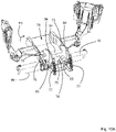
- Figures 2 and 3 are perspective views of the unit 5 comprising the safety part 2 and the child seat 3 connected thereto.
- the child seat 3 comprises a harness system 7 comprising two shoulder belts 8 and a crotch belt 9.
- the two shoulder belts 8 and the crotch belt 9 can be connected to each other by means of a lock 10.
- the shoulder belts 8 extend through holes 11 in a back portion 12 of the child seat 3.
- At the rear of the back portion 12 the shoulder belts 8 are connected to a single tensioner belt 13.
- the tensioner belt 13 extends through a tensioner 14 located near a front of the child seat 3.
- the connection of the crotch belt 9 to the child seat 3 is located on a seat portion 15 of the child seat 3 between the tensioner 14 and the back portion 12.
- Such harness system 7 is well known in the art and will therefor not further be explained.
- Figure 3 shows the unit 5 from below.
- the safety part 2 comprises at a side remote of the handle 6, two pens 16, 17 extending parallel to each other and perpendicular to the longitudinal direction of the safety part 2.
- Figure 4A shows the unit 5 comprising the safety part 2 and the child seat 3 connected thereto above a base 20 just before moving the unit 5 in a direction Po towards the base 20 to connect it to the base 20.
- the base 20 is identical to the base as shown in EP2210768 of the same applicant as the present application.
- the base 20 comprises four hooks 21, 22 (only two are visible) each being rotatable with respect to the base 20 around an axis 23, 24.
- Two hooks 21 are located near the front side of the base 20 whilst two other hooks 22 are located near the rear side 25 of the base 20.
- the hooks 21, 22 are in a opened position, In a locked position an abutment surface 26 of each hook 21, 22 is located in a recess (not shown) of the base 20 whilst a gripping surface 27 on each hook 21, 22 are located outside the recess.
- Each hook 21, 22 is connected to a spring 28 forcing the hook 21, 22 to the opened position.
- the hooks 21, 22 are being moved by means of a slide 29 of the base 20 to the opened position wherein the pens 16, 17 can be respectively connected to the hooks 22, 21 by pushing the pens 16, 17 onto the abutment surface 26 of the respective hook 21, 22 due to which the hooks 21, 22 will pivot around axis 23, 24 against spring force of the springs 28 to the locked position.
- the pens 16, 17 will than be located in notches 30, 31 of the hooks 21, 22.
- the hooks 21, 22 will be locked by locking means.
- the exact working of the base 20 is described in detail in EP2210768 and will therefor not further be explained. Other well known means to connect the safety part 3 to the base 20 are also possible.
- the base 20 is also provided with hooks 33 near the rear side 25 thereof to connect the base 20 to ISOFIX-connectors 34 mounted in a vehicle.
- the base 20 is also provided with a leg 35 resting with an end remote of the base 20 on a floor of a vehicle. Such a leg 35 is well known and will therefore not be further explained.
- Figure 4B shows the unit 5 as mounted on the base 20 to form a child seat transporting system 1 to be used in a vehicle.
- Figure 4C shows that the child seat 3 has been removed from the safety part 2 after disconnecting the connection between them as will be explained here below.
- the handle 6 is first pivoted in a direction as indicated by arrow P1 about pivot axis 36 towards the rear side 25 of the base 20 to provide more space for the removal of the child seat 3.
- the use of only the child seat 3 to transport a child located therein and being hold by means of the harness has the advantage that a user only needs to carry the relatively light weighted child seat 3 and the child, whereas the heavier, more sturdy safety part 2 can remain on the base 20 inside the vehicle.
- the child seat 3 has a width W2 being smaller than the width W1 of the safety part 2.
- the width W1 is 440 millimetre
- W2 is 272 millimetre.
- Figure 5A shows the unit 5 comprising the safety part 2 and the child seat 3 connected thereto above a frame 40 of a stroller 41 just before connecting the unit 5 to the frame 40.
- the frame 40 of the stroller 41 is identical to the frame as shown in EP2108566B1 of the same applicant as the present application.
- the safety part 2 is provided on both longitudinal sides with first connecting elements 42 (see figures 5D and 5E ) whilst the frame 40 of the stroller 41 is provided with two second connecting elements 43.
- the first connecting elements 42 of the safety part 2 can be detachably connected to the second connecting elements 43 of the frame 40 of the stroller 41.
- the exact working of the connecting elements 42, 43 is described in detail in EP2108566B1 and will therefor not further be explained.
- the stroller 41 is preferably foldable and also comprises in a well known manner wheels 44 and a push bar 45. Other well known means to connect the safety part 3 to the frame 40 of the stroller 41 are also possible.
- Figure 5B shows the unit 5 as mounted on the frame 40 of the stroller 41 to form a child seat transporting system 1.
- Figure 5C shows that the child seat 3 has been removed from the safety part 2 after disconnecting the connection between them and moving the unit 5 in a direction P4 away from the safety part 2 mounted on the stroller 41 as will be explained here below.
- the handle 6 is first pivoted in a direction as indicated by arrow P1 about pivot axis 36 to provide more space for the removal of the child seat 3.
- the use of only the child seat 3 to transport a child located therein and being hold by means of the harness has the advantage that a user only needs to carry the relatively light weighted child seat 3 and the child, whereas the heavier and more sturdy safety part 2 can remain on the frame 40 of the stroller 41.
- FIGS 6A-6C show different views of the child seat 3.
- the child seat 3 comprises a shell 51 made of plastic such as polypropylene (PP).
- PP polypropylene
- the same material can be used for the safety part 2.
- the wall thickness of the child seat 3 will be less than the wall thickness of the safety part 3.
- the child seat 3 comprises two protrusions 52.
- the protrusions 52 can be inserted into blind holes 53 of the safety part 2 to position the child seat 3 in the safety part 2 and to prevent the child seat 3 to be able to tilt with respect to the safety part 2.
- the child seat 3 can rest with the protrusions 52 on a flat surface when used without the safety part 2.
- the child seat 3 At a side below the seat portion 15 the child seat 3 comprises a pen 54 extending perpendicular to the longitudinal direction of the child seat 3 and perpendicular to side walls 61 of the shell 51. An end of the crotch belt 9 remote of the lock 10 is connected to the pen 54.
- the pen 54 is supported by and extends through two flanges 55 forming an integral part of the shell 51. Each end 56 of the pen 54 forms a first pen of the coupling mechanism of the child seat transporting system according to the present invention.
- FIGS 7A and 7B show different views of the safety part 2.
- the safety part 2 is made from a rigid plastic such as polypropylene (PP).
- PP polypropylene
- the weight of the child seat 3 is about 2 kilogram, the weight of the safety part 2 is about 3,4 kilogram, so the weight of the unit 5 is about 5,4 kilogram.
- Both the child seat 3 and the safety part 2 are preferably covered with a textile.
- the safety part 2 comprises a ring shaped frame 57 extending around the upper side of the safety part 2.
- the ring shaped frame 57 prevents the safety part 2 and therefor the child seat 3 when located inside the safety part 2 to be deformed in case of a crash like a car incident.
- the safety part 2 is provided with two enlarged passages 58 to reduce the weight of the safety part 2.
- the unit 5 comprising the safety part 2 and the child seat 3 fulfills the requirements regarding safety.
- the safety part 2 comprises a bottom part 59 to support the child seat 3.
- the blind holes 53 are located on both sides of the bottom part 59.
- the safety part 2 is near a front side thereof provided with two recesses 60 through which the pen 54 of the child seat 3 can be connected to two first hooks of the coupling mechanism of the child seat transporting system according to the present invention, as will be explained here below.
- Figures 8-11 show a first embodiment of the coupling mechanism 71 of the child seat transporting system according to the present invention.
- the coupling mechanism 71 comprises two coupling elements 72 each provided with the first hook 73 and a second hook 74.
- the coupling elements 72 are pivotable about pivot axes 75.
- Part of the coupling mechanism 71 is also pen 54 of the child seat 3 as well as pen 16 of the safety part 2 by means of which the safety part 2 can be connected to the base 20.
- the pen 54 cooperates with first hooks 73 whilst the pen 16 cooperates with second hooks 74.
- pen 16 and axes 75 extend parallel to each other.
- Each coupling element 72 is also provided with a third hook 76.
- the third hook 76 is attached to a spring 77.
- the spring 77 is attached at an end remote of the third hook 76 to an operating device 78.
- the coupling elements 72 are in a first position wherein the pen 54 of the child seat 2 is disconnected from the first hooks 73 and the child seat 3 and safety part 2 can be decoupled from each other. In the first position pen 16 of the safety part 2 is also is disconnected from the second hooks 74.
- Each coupling elements 72 comprises an abutment surface 79.
- Each first hook 73 comprises a notch 80 and a gripping surface 81.
- Each second hook 74 comprises a notch 82 and a gripping surface 83. In the first position the abutment surfaces 79 are located in the recesses 60 whilst the notches 80 and the gripping surfaces 81 on the first hook 73 are located outside the recesses 60.
- Each coupling elements 72 also comprises a locking surface 84.
- the protrusions 52 of the child seat 3 are inserted into the blind holes 53 of the safety part 2 and the pen 54 of the child seat 3 is brought into the recesses 60 and is pressed with a pressing force against the abutment surfaces 79 of the coupling elements 72. Due to this pressing force, the coupling elements 72 are being pivoted about the pivot axes 75 against spring force of the springs 77 in a direction indicated by arrow P2 to a second position.
- the pen 54 of the child seat 3 is located in the notches 80 of the first hooks 73 and engaged to the safety part 2 by means of the first hooks 73 and the gripping surfaces 81 thereof, whilst the pen 16 of the safety part 2 is located in the notches 82 of the second hooks 74.
- the pen 54 of the child seat 3 is directly coupled via the coupling elements 72 to the pen 16 of the safety part 2.
- the safety part 2 is coupled by means of the pen 16 to the base 20
- the child seat 3 is directly coupled via the coupling elements 72 to the pen 16 of the safety part 2 and to the base 20.
- the pens 56, 16 and the coupling elements 72 are made of a strong material like metal so that relatively large forces can easily and efficient be transmitted from the pen 54 to the pen 16 and to the base 20.
- the crotch belt 9 is connected to the pen 54.
- the locking surfaces 84 of the coupling elements 72 are brought in contact with locking surface 85 on the operating device 78 to lock the coupling elements 72 and the hooks 73, 74 thereof in said second position.
- the operating device 78 is being pivoted about pivot axis 86 against spring force of springs 77 in a direction as indicated by arrow P3, whereby under spring force of the springs 77 the coupling elements 72 are being pivoted in a direction opposite to arrow P2.
- abudment surfaces 79 of the coupling elements 72 pushes the pen 54 slightly out of the notches 80, whereafter still under spring force of the springs 77 the coupling elements 72 pivot to the first position.
- an angle A between a first virtual line 90 between the first pen 54 of the child seat 3 and the pivot axis 75 and a second virtual line 91 between the second pen 16 of the safety part 2 and the pivot axis 75 is for example 102 degrees degrees.
- An angle B between the first virtual line 90 horizontal H is for example between 48 and 63 degrees, so for example 55 degrees.
- the angle B is less than 90 degrees, preferably less than 63 degrees and more preferably less than 55 degrees, the movement of pen 54 in vertical direction along the vertical V towards and against the abutment surfaces 79 will cause pivoting of the coupling elements 72 in the direction indicated by arrow P2.
- the angle A as well as the distance between the first pen 54 of the child seat 3 and the pivot axis 75 determines the force needed to pivot the coupling elements 72.
- the pivoting is independent of the location and distance of the pen 16 with respect to the pivot axis 75.
- the pen 54 is located almost exactly vertical above the pen 16. Due to the coupling elements 72 comprising the first and second hooks 73, 74a freedom to determine the locations of the pens 54, 16 and axis 75 is obtained, whilst still a direct transmission of the forces from the pen 54 via coupling element 72 to pen 16 is obtained.
- Figures 12A and 12B show a second embodiment of a coupling element 92 of a coupling mechanism of the child seat transporting system according to the invention.
- the coupling element 92 differs from the coupling element 72 in that it comprises a slotted hole 93 in which the pen 16 is located. A part of a wall 94 bounding the slotted hole 93 forms the second hook.
- Figure 13 is a perspective view of a person 101 carrying a unit 5 comprising a safety part 2 and a child seat 3 connected thereto with a hand 104.
- a child 102 is present in the child seat 3.
- the part 103 of the handle 6 extends perpendicular to the walking direction of the person.
- Safety part 2 and thus unit 5 has a width W1.
- Figure 14 is a perspective view of a person 101 carrying a child seat 3 by its handles 4 with a hand 104.
- the weight of the child seat 3 to be carried is less than the weight of the unit 5.
- the child seat 3 has in a direction perpendicular to the walking direction of the person a width W2 being smaller than the width W1 of unit 5 so that the child seat 3 can be held closer to the body of the person 101.
- This also makes it easier to carry the child seat 3.
- the difference can also easily be seen from the figures 16A and 16B showing respectively a rear view of a person carrying the unit 5 respectively a child seat 2.
- the orientation of the hand 104 is different. To carry the unit 5 the person must turn its wrist to be able to place its hand 104 on part 103 of the handle 6. To carry only the child seat 2 the person 101 can held its arm 105 almost flat along its body and does not need to turn its wrist.
- Figure 15 is a perspective view of a person carrying a child seat 2 by its arm 105. Due to the flexible handles 4 and the orientation thereof, the child seat 3 can also be easily carried close to its body on the persons arm 105.
- the child seat transporting system 1 has the advantage that the child can be transported in a number of different manners which can each time be chosen depending on the wishes of the person taking care of the child.
- the coupling mechanism comprises two coupling elements. However, it is also possible to use only one or more than two coupling elements.
- the safety part comprises ISOFIX-connectors so it can be directly connected to the vehicle seat without a vehicle belt.
Landscapes
- Engineering & Computer Science (AREA)
- Health & Medical Sciences (AREA)
- Child & Adolescent Psychology (AREA)
- General Health & Medical Sciences (AREA)
- Aviation & Aerospace Engineering (AREA)
- Transportation (AREA)
- Mechanical Engineering (AREA)
- Seats For Vehicles (AREA)
Description
- The invention relates to a child seat transporting system comprising a child seat and a supporting part for supporting the child seat, wherein the child seat is detachably connected to the supporting part,
-
EP2210768B1 disclosed a child seat transporting system provided with a base and a seat being detachably connected to the base. The base comprises four recesses and four hooks each being movable from a first position to a second position and vice versa. Two hooks are located near the front side of the base whilst two other hooks are located near the rear side of the base. Each hook is rotatable with respect to the base around a pivot axis. The hooks are rotatable against spring force from the first position to the second position. - The seat is provided on the lower part of a seat part with two longitudinal pens extending parallel to each other and located at a distance of each other corresponding to the distance between recesses of the base.
- In the first position each pen connected to the seat can be positioned in a corresponding recess of the base, whilst in the second position each pen is maintained in the corresponding recess by the respective hook.
- When a user puts the seat on the base, the pens are positioned in the recesses. By doing so each pen exerts a force on an abutment surface of the respective hook whereby the hook is rotated against the force of the spring about the respective pivot axis, to the second position in which the pen is located in a notch of the hook and engaged to the base by means of the hook and a gripping surface thereof.
- In the second position forces on the pen are directly transmitted via de hook to the pivot axis.
- To be able to rotate the hook about its pivot axis, by pressing the pen on the abutment surface in a first direction there must be a certain distance between the abutment surface and the pivot axis in a direction perpendicular to the first direction to obtain a desired lever arm to convert the pressing force into the rotational movement. A disadvantage of the known coupling mechanism is that when such distance and lever arm can not be realized due to for example constructional limitations, no such pen-hook coupling element can be used.
-
US10028592 B1 - At least one of the objects of the invention is to provide a child seat transporting system whereby forces can be transmitted from a pen to an axis, whilst the rotation of the hook is independent from the distance between and the position of the pen and the axis.
- This object is accomplished with the child seat transporting system according to the invention in that the support part comprises a safety part, wherein the child seat is detachably connected to the safety part, whereas the safety part is detachably connectable to a base being detachably connectable to a seat of a vehicle, and/or being detachably connectable to a frame of a stroller, which child seat transporting system further comprises at least one coupling mechanism for coupling the child seat to the safety part, wherein the safety part comprises at least one coupling element provided with at least a first hook, which coupling element being pivotable about a pivot axis, whilst the child seat comprises at least a first pen extending parallel to the pivot axis, wherein the coupling element is pivotable between a first position wherein the first pen is disconnected from the first hook and the child seat and the safety part can be decoupled from each other and a second position wherein the first pen is located in the first hook and the child seat to the safety part are detachably coupled to each other, wherein the safety part comprises a second pen extending parallel to the pivot axis at a distance thereof, whilst the coupling element comprises a second hook, wherein in the first position the second pen is disconnected from the second hook, whilst in the second position the second pen is located in the second hook, wherein the safety part is detachably connectable to the base by means of at least the second pen.
- When coupling the first pen of the child seat to the first hook of the coupling element of the safety part, the coupling element is being rotated about the pivot axis to the second position. By rotating the coupling element to the second position, the second hook is simultaneously coupled to the second pen. Forces on the first pen will be transmitted through the coupling element to the pivot axis and the axis of second pen. The second pen and the axis thereof can be located at any desired distance from the first pen and at any desired position with respect to the first pen. This provides a great degree of freedom for the design of the supporting part as well as of the child seat as well as the possibility of a compact geometry.
- The safety part provides safety to the child seat. The child seat can be used and carried around independently from the safety part or can be used and carried around together with the safety part. The safety part can be mounted on the base being connected on a seat of a vehicle or can be mounted on a frame of a stroller. This provides a single child seat transporting system with a number of different purposes. An advantage to be able to detachably connect the safety part to the frame of the stroller, whilst the child seat is detachably connected to the safety part, is that only the width of the safety part needs to be such to be able to connect it to the frame. The child child seat can have a smaller width. This makes it easier to carry only the child seat with a child located therein. If desired the user can also carry the safety part with the child seat and a child located therein. Such a unit will be heavier but also more sturdy.
- An embodiment of the child seat transporting system according to the invention is characterized in that the child seat comprises a harness system provided with at least shoulder belts and a crotch belt, which crotch belt of the child seat is with one end connected to the first pen of the at least one coupling mechanism.
- This has the advantage that forces on the crotch belt will be transmitted directly via the first pen of the child seat, the coupling element and the second pen of the safety part to the base.
- Another embodiment of the coupling mechanism according to the invention is characterized in that the coupling element comprises a slotted hole, wherein part of a wall of the slotted hole forms the second hook.
- With such a slotted hole, the second pen will always be connected to the coupling element. Such a slotted hole provides a strong coupling element.
- Another embodiment of the coupling mechanism according to the invention is characterized in that the coupling element is pivotable against spring force from the first to the second position, in which second position the coupling element is lockable.
- Due to the spring force the coupling element will be automatically move to the first position as soon as the coupling element is being unlocked from its the second position.
- The the child seat transporting system according to the invention will further be explained with reference to the drawings, wherein,
-
figure 1 is a side view showing a safety part and a child seat according the a first embodiment of the child seat transporting system according to the invention in a disconnected and connected position, -
figure 2 and3 are a perspective views of the safety part and the child seat connected thereto as shown infigure 1 . -
figures 4A ,4B and4C are a cross section and side views of the safety part with the child seat on a base of the child seat transporting system according to the invention in a dismounted and mounted position as well as in a position wherein the child seat is disconnected from the safety part being connected to the base, -
figures 5A-5EC are side views of the safety part with the child seat on a frame of a stroller of the child seat transporting system according to the invention in a dismounted and mounted position as well as in a position wherein the child seat is disconnected from the safety part being connected to the frame of the stroller as well as of a safety part with a first connecting element and an enlarged view of such first connecting element, -
figures 6A ,6B and6C are different perspective views of the child seat as shown infigure 1 , -
figures 7A and7B are a perspective view and an enlarged perspective view of the safety part as shown infigure 1 , -
figure 8 is a perspective view of coupling mechanisms of the child seat transporting system according to the invention in a first disconnected position thereof, -
figures 9A and 9B are a perspective view and side view of a detail offigure 8 , showing coupling mechanisms of the child seat transporting system according to the invention in the first disconnected position thereof, -
figures 10A and10B are perspective views of coupling mechanisms of the child seat transporting system according to the invention in a second connected position thereof, -
figures 11A and 11B are a perspective view and side view of a detail offigure 10 , showing coupling mechanisms of the child seat transporting system according to the invention in the second connected position thereof, -
figures 12A and 12B are side views of a second embodiment of a coupling mechanism of the child seat transporting system according to the invention in a first disconnected position and a second connected position respectively, -
figure 13 is a perspective view of a person carrying a unit comprising a safety part and a child seat connected thereto, -
figure 14 is a perspective view of a person carrying a child seat by its hand, -
figure 15 is a perspective view of a person carrying a child seat by its arm, -
figures 16A and 16B are rear views of a person carrying a unit comprising a safety part and a child seat connected thereto respectively a child seat. - In the drawings, like reference numerals refer to like elements.
-
Figure 1 shows a side view of a childseat transporting system 1 according to the invention comprising asafety part 2 and achild seat 3. On the left side offigure 1 thechild seat 3 is positioned above thesafety part 2 just before connecting thechild seat 3 to thesafety part 2 as will be explained in more detail here below. Thechild seat 3 which can be used to transport a child by carrying it on twohandles 4 of thechild seat 3, which handles 4 extend in longitudinal direction ofchild seat 3. Preferably thehandles 4 are retractable under spring force. - On the right side of
figure 1 thechild seat 3 is inside thesafety part 2 and is connected thereto to form anintegrated unit 5. Theunit 5 can be used to transport a child by carrying it on theU-shaped handle 6 of thesafety part 2, which handle 6 is connected to two longitudinal sides of thesafety part 2 or by carrying it on twohandles 4 of thechild seat 3. - The
unit 5 can be mounted on a seat of a vehicle and connected thereto by means of vehicle seat belts (not shown) to be guided throughhooks safety part 2. -
Figures 2 and3 are perspective views of theunit 5 comprising thesafety part 2 and thechild seat 3 connected thereto. - As can be seen in
figure 2 thechild seat 3 comprises aharness system 7 comprising twoshoulder belts 8 and acrotch belt 9. The twoshoulder belts 8 and thecrotch belt 9 can be connected to each other by means of alock 10. Theshoulder belts 8 extend throughholes 11 in aback portion 12 of thechild seat 3. At the rear of theback portion 12 theshoulder belts 8 are connected to asingle tensioner belt 13. Thetensioner belt 13 extends through atensioner 14 located near a front of thechild seat 3. The connection of thecrotch belt 9 to thechild seat 3 is located on aseat portion 15 of thechild seat 3 between thetensioner 14 and theback portion 12.Such harness system 7 is well known in the art and will therefor not further be explained. -
Figure 3 shows theunit 5 from below. As can be seen thesafety part 2 comprises at a side remote of thehandle 6, twopens safety part 2. -
Figure 4A shows theunit 5 comprising thesafety part 2 and thechild seat 3 connected thereto above a base 20 just before moving theunit 5 in a direction Po towards the base 20 to connect it to thebase 20. - The
base 20 is identical to the base as shown inEP2210768 of the same applicant as the present application. - The
base 20 comprises fourhooks 21, 22 (only two are visible) each being rotatable with respect to thebase 20 around anaxis other hooks 22 are located near therear side 25 of thebase 20. Infigure 4A thehooks abutment surface 26 of eachhook gripping surface 27 on eachhook - Each
hook spring 28 forcing thehook unit 5 on thebase 20, thehooks slide 29 of the base 20 to the opened position wherein thepens hooks pens abutment surface 26 of therespective hook hooks axis springs 28 to the locked position. Thepens notches hooks hooks base 20 is described in detail inEP2210768 and will therefor not further be explained. Other well known means to connect thesafety part 3 to the base 20 are also possible. - The
base 20 is also provided withhooks 33 near therear side 25 thereof to connect the base 20 to ISOFIX-connectors 34 mounted in a vehicle. Thebase 20 is also provided with aleg 35 resting with an end remote of the base 20 on a floor of a vehicle. Such aleg 35 is well known and will therefore not be further explained. -
Figure 4B shows theunit 5 as mounted on the base 20 to form a childseat transporting system 1 to be used in a vehicle. -
Figure 4C shows that thechild seat 3 has been removed from thesafety part 2 after disconnecting the connection between them as will be explained here below. Preferably thehandle 6 is first pivoted in a direction as indicated by arrow P1 aboutpivot axis 36 towards therear side 25 of the base 20 to provide more space for the removal of thechild seat 3. The use of only thechild seat 3 to transport a child located therein and being hold by means of the harness has the advantage that a user only needs to carry the relatively lightweighted child seat 3 and the child, whereas the heavier, moresturdy safety part 2 can remain on thebase 20 inside the vehicle. Thechild seat 3 has a width W2 being smaller than the width W1 of thesafety part 2. For example, the width W1 is 440 millimetre, whilst W2 is 272 millimetre. -
Figure 5A shows theunit 5 comprising thesafety part 2 and thechild seat 3 connected thereto above aframe 40 of astroller 41 just before connecting theunit 5 to theframe 40. - The
frame 40 of thestroller 41 is identical to the frame as shown inEP2108566B1 of the same applicant as the present application. - The
safety part 2 is provided on both longitudinal sides with first connecting elements 42 (seefigures 5D and 5E ) whilst theframe 40 of thestroller 41 is provided with two second connectingelements 43. The first connectingelements 42 of thesafety part 2 can be detachably connected to the second connectingelements 43 of theframe 40 of thestroller 41. The exact working of the connectingelements EP2108566B1 and will therefor not further be explained. Thestroller 41 is preferably foldable and also comprises in a wellknown manner wheels 44 and apush bar 45. Other well known means to connect thesafety part 3 to theframe 40 of thestroller 41 are also possible. -
Figure 5B shows theunit 5 as mounted on theframe 40 of thestroller 41 to form a childseat transporting system 1. -
Figure 5C shows that thechild seat 3 has been removed from thesafety part 2 after disconnecting the connection between them and moving theunit 5 in a direction P4 away from thesafety part 2 mounted on thestroller 41 as will be explained here below. Preferably thehandle 6 is first pivoted in a direction as indicated by arrow P1 aboutpivot axis 36 to provide more space for the removal of thechild seat 3. The use of only thechild seat 3 to transport a child located therein and being hold by means of the harness has the advantage that a user only needs to carry the relatively lightweighted child seat 3 and the child, whereas the heavier and moresturdy safety part 2 can remain on theframe 40 of thestroller 41. -
Figures 6A-6C show different views of thechild seat 3. Thechild seat 3 comprises ashell 51 made of plastic such as polypropylene (PP). The same material can be used for thesafety part 2. However the wall thickness of thechild seat 3 will be less than the wall thickness of thesafety part 3. At a rear side of theback portion 12 thechild seat 3 comprises twoprotrusions 52. Theprotrusions 52 can be inserted intoblind holes 53 of thesafety part 2 to position thechild seat 3 in thesafety part 2 and to prevent thechild seat 3 to be able to tilt with respect to thesafety part 2. Furthermore thechild seat 3 can rest with theprotrusions 52 on a flat surface when used without thesafety part 2. - At a side below the
seat portion 15 thechild seat 3 comprises apen 54 extending perpendicular to the longitudinal direction of thechild seat 3 and perpendicular to side walls 61 of theshell 51. An end of thecrotch belt 9 remote of thelock 10 is connected to thepen 54. Thepen 54 is supported by and extends through twoflanges 55 forming an integral part of theshell 51. Eachend 56 of thepen 54 forms a first pen of the coupling mechanism of the child seat transporting system according to the present invention. -
Figures 7A and7B show different views of thesafety part 2. Thesafety part 2 is made from a rigid plastic such as polypropylene (PP). The weight of thechild seat 3 is about 2 kilogram, the weight of thesafety part 2 is about 3,4 kilogram, so the weight of theunit 5 is about 5,4 kilogram. Both thechild seat 3 and thesafety part 2 are preferably covered with a textile. - The
safety part 2 comprises a ring shapedframe 57 extending around the upper side of thesafety part 2. The ring shapedframe 57 prevents thesafety part 2 and therefor thechild seat 3 when located inside thesafety part 2 to be deformed in case of a crash like a car incident. Thesafety part 2 is provided with twoenlarged passages 58 to reduce the weight of thesafety part 2. - Due to the
safety part 2, theunit 5 comprising thesafety part 2 and thechild seat 3 fulfills the requirements regarding safety. - The
safety part 2 comprises abottom part 59 to support thechild seat 3. Theblind holes 53 are located on both sides of thebottom part 59. Thesafety part 2 is near a front side thereof provided with tworecesses 60 through which thepen 54 of thechild seat 3 can be connected to two first hooks of the coupling mechanism of the child seat transporting system according to the present invention, as will be explained here below. -
Figures 8-11 show a first embodiment of thecoupling mechanism 71 of the child seat transporting system according to the present invention. - The
coupling mechanism 71 comprises twocoupling elements 72 each provided with thefirst hook 73 and asecond hook 74. Thecoupling elements 72 are pivotable about pivot axes 75. Part of thecoupling mechanism 71 is also pen 54 of thechild seat 3 as well aspen 16 of thesafety part 2 by means of which thesafety part 2 can be connected to thebase 20. Thepen 54 cooperates withfirst hooks 73 whilst thepen 16 cooperates withsecond hooks 74. - As can be seen in
figure 8 pen 54,pen 16 and axes 75 extend parallel to each other. - Each
coupling element 72 is also provided with athird hook 76. Thethird hook 76 is attached to aspring 77. Thespring 77 is attached at an end remote of thethird hook 76 to anoperating device 78. - In the
figures 8 ,9A and 9B thecoupling elements 72 are in a first position wherein thepen 54 of thechild seat 2 is disconnected from thefirst hooks 73 and thechild seat 3 andsafety part 2 can be decoupled from each other. In thefirst position pen 16 of thesafety part 2 is also is disconnected from the second hooks 74. - Each
coupling elements 72 comprises anabutment surface 79. Eachfirst hook 73 comprises anotch 80 and agripping surface 81. Eachsecond hook 74 comprises anotch 82 and agripping surface 83. In the first position the abutment surfaces 79 are located in therecesses 60 whilst thenotches 80 and thegripping surfaces 81 on thefirst hook 73 are located outside therecesses 60. - Each
coupling elements 72 also comprises a lockingsurface 84. - When positioning the
child seat 3 on thesafety part 2 theprotrusions 52 of thechild seat 3 are inserted into theblind holes 53 of thesafety part 2 and thepen 54 of thechild seat 3 is brought into therecesses 60 and is pressed with a pressing force against the abutment surfaces 79 of thecoupling elements 72. Due to this pressing force, thecoupling elements 72 are being pivoted about the pivot axes 75 against spring force of thesprings 77 in a direction indicated by arrow P2 to a second position. In the second position, as shown infigures 10A-11B , thepen 54 of thechild seat 3 is located in thenotches 80 of thefirst hooks 73 and engaged to thesafety part 2 by means of thefirst hooks 73 and thegripping surfaces 81 thereof, whilst thepen 16 of thesafety part 2 is located in thenotches 82 of the second hooks 74. In this second position thepen 54 of thechild seat 3 is directly coupled via thecoupling elements 72 to thepen 16 of thesafety part 2. In case that thesafety part 2 is coupled by means of thepen 16 to thebase 20, thechild seat 3 is directly coupled via thecoupling elements 72 to thepen 16 of thesafety part 2 and to thebase 20. Preferably thepens coupling elements 72 are made of a strong material like metal so that relatively large forces can easily and efficient be transmitted from thepen 54 to thepen 16 and to thebase 20. Preferably thecrotch belt 9 is connected to thepen 54. When theunit 5 is mounted on the base 20 forces on theharness 7, for example in case of a crash, will be transmitted via thecrotch belt 9, thepen 54, thecoupling elements 72 and thepen 16 directly to thebase 20. This has the advantage that the other parts of thechild seat 3 can be less strong, which provides a great degree of freedom of design. - In
figure 7B thecoupling elements 72 pivot in a clockwise direction from the first to the second position. - In the second position the locking surfaces 84 of the
coupling elements 72 are brought in contact with lockingsurface 85 on the operatingdevice 78 to lock thecoupling elements 72 and thehooks - To unlock the locking surfaces 84, 85 the operating
device 78 is being pivoted aboutpivot axis 86 against spring force ofsprings 77 in a direction as indicated by arrow P3, whereby under spring force of thesprings 77 thecoupling elements 72 are being pivoted in a direction opposite to arrow P2. When pivoting thecoupling elements 72 in a direction opposite to arrow P2, abudment surfaces 79 of thecoupling elements 72 pushes thepen 54 slightly out of thenotches 80, whereafter still under spring force of thesprings 77 thecoupling elements 72 pivot to the first position. - As can be see in
figure 9B an angle A between a firstvirtual line 90 between thefirst pen 54 of thechild seat 3 and thepivot axis 75 and a secondvirtual line 91 between thesecond pen 16 of thesafety part 2 and thepivot axis 75 is for example 102 degrees degrees. An angle B between the firstvirtual line 90 horizontal H is for example between 48 and 63 degrees, so for example 55 degrees. As long as the angle B is less than 90 degrees, preferably less than 63 degrees and more preferably less than 55 degrees, the movement ofpen 54 in vertical direction along the vertical V towards and against the abutment surfaces 79 will cause pivoting of thecoupling elements 72 in the direction indicated by arrow P2. The angle A as well as the distance between thefirst pen 54 of thechild seat 3 and thepivot axis 75 determines the force needed to pivot thecoupling elements 72. The pivoting is independent of the location and distance of thepen 16 with respect to thepivot axis 75. As can be seen infigure 9B thepen 54 is located almost exactly vertical above thepen 16. Due to thecoupling elements 72 comprising the first andsecond hooks 73, 74a freedom to determine the locations of thepens axis 75 is obtained, whilst still a direct transmission of the forces from thepen 54 viacoupling element 72 to pen 16 is obtained. -
Figures 12A and 12B show a second embodiment of acoupling element 92 of a coupling mechanism of the child seat transporting system according to the invention. - The
coupling element 92 differs from thecoupling element 72 in that it comprises a slottedhole 93 in which thepen 16 is located. A part of awall 94 bounding the slottedhole 93 forms the second hook. - In
figure 12A thepen 16 is located against afirst end 95 of the slottedhole 93. This position defines the first position of thecoupling element 92. - In
figure 12B thepen 16 is located against asecond end 96 of the slottedhole 93. This position defines the second position of thecoupling element 92. -
Figure 13 is a perspective view of aperson 101 carrying aunit 5 comprising asafety part 2 and achild seat 3 connected thereto with ahand 104. Achild 102 is present in thechild seat 3. As can be seen also infigure 16A , thepart 103 of thehandle 6 extends perpendicular to the walking direction of the person.Safety part 2 and thusunit 5 has a width W1. -
Figure 14 is a perspective view of aperson 101 carrying achild seat 3 by itshandles 4 with ahand 104. The weight of thechild seat 3 to be carried is less than the weight of theunit 5. Furthermore, thechild seat 3 has in a direction perpendicular to the walking direction of the person a width W2 being smaller than the width W1 ofunit 5 so that thechild seat 3 can be held closer to the body of theperson 101. This also makes it easier to carry thechild seat 3. The difference can also easily be seen from thefigures 16A and 16B showing respectively a rear view of a person carrying theunit 5 respectively achild seat 2. Also the orientation of thehand 104 is different. To carry theunit 5 the person must turn its wrist to be able to place itshand 104 onpart 103 of thehandle 6. To carry only thechild seat 2 theperson 101 can held itsarm 105 almost flat along its body and does not need to turn its wrist. -
Figure 15 is a perspective view of a person carrying achild seat 2 by itsarm 105. Due to theflexible handles 4 and the orientation thereof, thechild seat 3 can also be easily carried close to its body on the persons arm 105. - The child
seat transporting system 1 according to the invention has the advantage that the child can be transported in a number of different manners which can each time be chosen depending on the wishes of the person taking care of the child. - By the embodiment as shown in
figures 8-11 the coupling mechanism comprises two coupling elements. However, it is also possible to use only one or more than two coupling elements. - It is also possible that the safety part comprises ISOFIX-connectors so it can be directly connected to the vehicle seat without a vehicle belt.
-
- 1
- child seat transporting system
- 2
- safety part
- 3
- child seat
- 4
- handle
- 5
- unit
- 6
- handle
- 7
- harness system
- 8
- shoulder belt
- 9
- crotch belt
- 10
- lock
- 11
- hole
- 12
- back portion
- 13
- tensioner belt
- 14
- tensioner
- 15
- seat portion
- 16
- pen
- 17
- pen
- 18
- hook
- 19
- hook
- 20
- base
- 21
- hook
- 22
- hook
- 23
- axis
- 24
- axis
- 25
- rear side
- 26
- surface
- 27
- surface
- 28
- spring
- 29
- slide
- 30
- notch
- 31
- notch
- 33
- hook
- 34
- ISOFIX-connectors
- 35
- leg
- 36
- axis
- 40
- frame
- 41
- stroller
- 42
- first connecting element
- 43
- second connecting element
- 44
- wheel
- 45
- push bar
- 51
- shell
- 52
- protrusion
- 53
- blind hole
- 54
- pen
- 55
- flange
- 56
- end
- 57
- ring shaped frame
- 58
- passage
- 59
- bottom part
- 60
- recess
- 61
- side wall
- 71
- coupling mechanism
- 72
- coupling element
- 73
- first hook
- 74
- second hook
- 75
- pivot axis
- 76
- third hook
- 77
- spring
- 78
- operating device
- 79
- abutment surface
- 80
- notch
- 81
- gripping surface
- 82
- notch
- 83
- gripping surface
- 84
- locking surfaces
- 85
- locking surface
- 86
- pivot axis
- 90
- first virtual line
- 91
- second virtual line
- 92
- coupling element
- 93
- slotted hole
- 94
- wall
- 95
- first end
- 96
- second end
- 101
- person
- 103
- part
- 104
- hand
- 105
- arm
- A
- angle
- B
- angle
- H
- horizontal
- Po
- arrow
- P1
- arrow
- P2
- arrow
- P3
- arrow
- P4
- arrow
- V
- vertical
- W1
- width
- W2
- width
Claims (5)
- Child seat transporting system (1) comprising a child seat (3) and a supporting part for supporting the child seat (3), wherein the child seat (3) is detachably connected to the supporting part, characterized in that the support part comprises a safety part (2), wherein the child seat (3) is detachably connected to the safety part (2), whereas the safety part (2) is detachably connectable to a base (20) being detachably connectable to a seat of a vehicle, and/or being detachably connectable to a frame of a stroller (41), which child seat transporting system (1) further comprises at least one coupling mechanism (71) for coupling the child seat (3) to the safety part (2), wherein the safety part (2) comprises at least one coupling element (72) provided with at least a first hook (73), which coupling element (72) being pivotable about a pivot axis (75), whilst the child seat (3) comprises at least a first pen (54) extending parallel to the pivot axis (75), wherein the coupling element (72) is pivotable between a first position wherein the first pen (54) is disconnected from the first hook (73) and the child seat (3) and the safety part (2) can be decoupled from each other and a second position wherein the first pen (54) is located in the first hook (73) and the child seat (3) to the safety part (2) are detachably coupled to each other, wherein the safety part (2) comprises a second pen (16) extending parallel to the pivot axis (75) at a distance thereof, whilst the coupling element (72) comprises a second hook (74), wherein in the first position the second pen (16) is disconnected from the second hook (74), whilst in the second position the second pen (16) is located in the second hook (74), wherein the safety part (2) is detachably connectable to the base (20) by means of at least the second pen (16).
- Child seat transporting system (1) according to claim 1, characterized in that the child seat (3) comprises a harness system (7) provided with at least shoulder belts (8) and a crotch belt (9), which crotch belt (9) of the child seat (3) is with one end connected to the first pen (54) of the at least one coupling mechanism (71).
- Child seat transporting system (1) according to claim 1 or 2, characterized in that the coupling element (72) comprises a slotted hole (93), wherein part of a wall of the slotted hole (93) forms the second hook (74).
- Child seat transporting system (1) according to claim 1, 2 or 3, characterized in that the coupling element (72) is pivotable against spring force from the first to the second position, in which second position the coupling element (72) is lockable.
- Child seat transporting system (1) according to one of the preceding claims, characterized in that the safety part (2) is directly detachably connectable to a seat of a vehicle.
Applications Claiming Priority (1)
| Application Number | Priority Date | Filing Date | Title |
|---|---|---|---|
| NL2023470A NL2023470B1 (en) | 2019-07-10 | 2019-07-10 | Coupling mechanism as well as a child seat transporting system provided with at least one such a coupling mechanism |
Publications (2)
| Publication Number | Publication Date |
|---|---|
| EP3763565A1 EP3763565A1 (en) | 2021-01-13 |
| EP3763565B1 true EP3763565B1 (en) | 2022-03-30 |
Family
ID=67876057
Family Applications (1)
| Application Number | Title | Priority Date | Filing Date |
|---|---|---|---|
| EP20184918.9A Active EP3763565B1 (en) | 2019-07-10 | 2020-07-09 | A child seat transporting system |
Country Status (6)
| Country | Link |
|---|---|
| US (1) | US11472316B2 (en) |
| EP (1) | EP3763565B1 (en) |
| CN (1) | CN214874353U (en) |
| ES (1) | ES2912563T3 (en) |
| NL (1) | NL2023470B1 (en) |
| PL (1) | PL3763565T3 (en) |
Families Citing this family (2)
| Publication number | Priority date | Publication date | Assignee | Title |
|---|---|---|---|---|
| CN115844166A (en) * | 2021-09-24 | 2023-03-28 | 明门瑞士股份有限公司 | Baby sleeping basket |
| GB2623504A (en) * | 2022-10-13 | 2024-04-24 | Icandy World Ltd | Car seats, bases and systems |
Family Cites Families (51)
| Publication number | Priority date | Publication date | Assignee | Title |
|---|---|---|---|---|
| US3596986A (en) | 1970-03-30 | 1971-08-03 | Gen Motors Corp | Baby seat |
| WO1997007716A1 (en) | 1995-08-25 | 1997-03-06 | Ga International, Inc. | Child safety seat |
| US5806924A (en) | 1996-12-17 | 1998-09-15 | Cambridge Industries, Inc. | Baby seat |
| US6017088A (en) | 1996-12-27 | 2000-01-25 | Evenflo Company, Inc. | Convertible infant carrier/restraint system |
| US6386632B1 (en) | 1997-10-14 | 2002-05-14 | Xsci, Inc. | Convertible child safety seat |
| US5893606A (en) | 1997-12-12 | 1999-04-13 | Chiang; Mao-Chin | Multifunctional children gear |
| JP3656512B2 (en) * | 1999-05-10 | 2005-06-08 | タカタ株式会社 | child seat |
| US6517153B1 (en) | 2000-03-03 | 2003-02-11 | Marvelee Brewer | All weather protective infant carrier cover/activity center |
| NO20003859L (en) | 2000-07-27 | 2002-01-28 | Torgersen Hans & Soenn | Child restraint system |
| US6199949B1 (en) * | 2000-07-31 | 2001-03-13 | Dasilva Eric S. | Child safety seat |
| GB2377677B (en) | 2001-07-19 | 2004-09-29 | Andrew Bargery | Transporter |
| US6913313B2 (en) | 2002-03-04 | 2005-07-05 | Baby Trend, Inc. | Infant car seat handle and handle lock mechanism |
| US6715828B1 (en) | 2002-10-07 | 2004-04-06 | Kenny Cheng | Infant carrier |
| FI20040603A (en) | 2004-04-28 | 2005-10-29 | Klippan Ab Oy | Child seat |
| US7597396B2 (en) | 2004-04-30 | 2009-10-06 | Chicco Usa, Inc. | Infant travel system |
| DE102004049919A1 (en) | 2004-10-13 | 2006-04-20 | SCHÄFER, Friedrich | Two-part baby seat to transport and fix in a car consists of inner and outer shells, of which outer part is fastened in car and inner part removed and used outside it |
| US20080313812A1 (en) | 2005-03-08 | 2008-12-25 | Deirde Maree Reeves | Portable Infant Support Apparatus |
| US7810682B2 (en) | 2005-03-24 | 2010-10-12 | Cosco Management, Inc. | Juvenile seat with removable, wearable infant carrier sling |
| GB2429401B (en) | 2005-08-25 | 2009-06-24 | Abs Comtech Ltd | Child car seat |
| US20080067845A1 (en) | 2006-02-28 | 2008-03-20 | Britax Child Safety, Inc. | Carry handle seat latch for child safety seat |
| EP1969975A1 (en) | 2007-03-15 | 2008-09-17 | Team-Tex | Device for transporting a child |
| EP1970247A1 (en) | 2007-03-15 | 2008-09-17 | Team-Tex | Device for mounting a child seat in a car and a child seat |
| NL1035275C2 (en) | 2008-04-09 | 2009-10-12 | Maxi Miliaan Bv | Assembly comprising an undercarriage and a child's seat that can be detachably connected to the undercarriage, such an undercarriage as well as such a child's seat. |
| NL1036453C2 (en) * | 2009-01-23 | 2010-07-26 | Maxi Miliaan Bv | Child vehicle seat. |
| US8186757B2 (en) * | 2009-03-04 | 2012-05-29 | Cosco Management, Inc. | Child restraint system including a stationary seat support and a removable juvenile vehicle seat on the seat support |
| US8210610B2 (en) | 2009-03-16 | 2012-07-03 | Graco Children's Products Inc. | Reconfigurable child seat assembly for a juvenile product |
| CN101837798A (en) | 2009-03-16 | 2010-09-22 | 葛莱儿婴儿产品股份有限公司 | The stroller adapter that is used for infant car seat |
| US8702169B2 (en) | 2010-06-04 | 2014-04-22 | Arvin Grande Abadilla | Method and apparatus for an infant safety seat |
| US8998312B2 (en) | 2010-10-29 | 2015-04-07 | Wonderland Nurserygoods Company Limited | Infant safety seat |
| DE202011000229U1 (en) | 2011-01-31 | 2011-06-09 | Curt Würstl Vermögensverwaltungs-GmbH & Co. KG, 95032 | Baby carrier in the form of a bucket seat |
| CN202234240U (en) | 2011-07-08 | 2012-05-30 | 克斯克管理公司 | Baby carriage with handle |
| US9751433B2 (en) | 2011-10-06 | 2017-09-05 | Thorley Industries Llc | Child restraint system with user interface |
| CN202843043U (en) | 2012-09-07 | 2013-04-03 | 明门(中国)幼童用品有限公司 | Handle folding structure and children carrying basket with the same |
| US10220734B2 (en) | 2013-03-05 | 2019-03-05 | Pidyon Controls Inc. | Car seat |
| US8911015B2 (en) | 2013-03-05 | 2014-12-16 | Yochanan Cohen | Car seat |
| US8960794B2 (en) | 2013-04-02 | 2015-02-24 | John David St. Pierre | Child carrier and car seat combination |
| CN203713613U (en) * | 2013-08-15 | 2014-07-16 | 中山市隆成日用制品有限公司 | Safety display equipment capable of locking infant automobile safety chair |
| US9119483B1 (en) | 2014-03-14 | 2015-09-01 | Dorel Juvenile Group, Inc. | Child restraint system |
| US9487111B2 (en) | 2014-03-24 | 2016-11-08 | Jason Lake | Spinning infant car seat |
| EP3142891B1 (en) | 2014-05-16 | 2021-01-06 | Dorel France | Child restraint |
| US9771007B2 (en) | 2015-01-29 | 2017-09-26 | Artsana USA, Inc | Multi-position rear-facing child seat |
| DE102015113852A1 (en) | 2015-08-20 | 2017-02-23 | Recaro Child Safety Gmbh & Co. Kg | Child seat system |
| CA2940813C (en) | 2015-09-03 | 2017-08-22 | Wonderland Nurserygoods Company Limited | Infant carrier |
| US10363842B2 (en) | 2015-09-11 | 2019-07-30 | Dorel Juvenile Group, Inc. | Vehicle anchor system for juvenile seat base |
| CN206383858U (en) | 2017-01-03 | 2017-08-08 | 明门瑞士股份有限公司 | The base and child safety seat of restricting vehicle chair backrest angle |
| CA3063406A1 (en) | 2017-05-17 | 2018-11-22 | Illa Designs, LLC | Car seat carrier |
| US10028592B1 (en) * | 2017-11-03 | 2018-07-24 | Delia P. Ruiz | Carrier with a multi-purpose handle assembly |
| US11134793B2 (en) | 2019-02-20 | 2021-10-05 | Dorel Juvenile Group, Inc. | Side carry handles for child carrier |
| US11034266B2 (en) | 2019-02-27 | 2021-06-15 | Dorel Juvenile Group, Inc. | Child restraint |
| US10894492B2 (en) | 2019-03-26 | 2021-01-19 | Toyota Motor Engineering & Manufacturing North America, Inc | Vehicle seats providing access to child seat release latches |
| US11541786B2 (en) | 2019-07-25 | 2023-01-03 | Dorel Juvenile Group, Inc. | Infant carrier |
-
2019
- 2019-07-10 NL NL2023470A patent/NL2023470B1/en not_active IP Right Cessation
-
2020
- 2020-07-07 US US16/922,407 patent/US11472316B2/en active Active
- 2020-07-09 EP EP20184918.9A patent/EP3763565B1/en active Active
- 2020-07-09 PL PL20184918.9T patent/PL3763565T3/en unknown
- 2020-07-09 ES ES20184918T patent/ES2912563T3/en active Active
- 2020-07-10 CN CN202021361349.5U patent/CN214874353U/en active Active
Also Published As
| Publication number | Publication date |
|---|---|
| EP3763565A1 (en) | 2021-01-13 |
| NL2023470B1 (en) | 2021-02-02 |
| ES2912563T3 (en) | 2022-05-26 |
| CN214874353U (en) | 2021-11-26 |
| US20210009012A1 (en) | 2021-01-14 |
| PL3763565T3 (en) | 2022-09-05 |
| US11472316B2 (en) | 2022-10-18 |
Similar Documents
| Publication | Publication Date | Title |
|---|---|---|
| EP3763565B1 (en) | A child seat transporting system | |
| EP3395646B1 (en) | Child stroller apparatus | |
| US7017921B2 (en) | Stroller with retaining mechanism | |
| US7441794B2 (en) | Foldable stroller | |
| CN210882284U (en) | Baby carriage with seat backrest capable of being linked to be folded | |
| US20100072731A1 (en) | Modular Stroller | |
| EP2014536B1 (en) | Foldable toy stroller | |
| EP3266655B1 (en) | Load carrier for a vehicle | |
| CN106394643B (en) | Folding baby carriage | |
| US8696063B2 (en) | Pivotable infant car seat | |
| JPS6339472B2 (en) | ||
| US20060131840A1 (en) | Children's stroller | |
| EP3763564A1 (en) | Child seat transporting system and safety part suitable for such a child seat transporting system | |
| US20090256406A1 (en) | Assembly Comprising a Chassis and a Child Seat Being Detachably Connectable to the Chassis, As Well As Such a Child Seat and Such a Chassis | |
| CN103386905B (en) | Child car seat and seat and base suitable for this child car seat | |
| CN109562772B (en) | Device for transporting children | |
| CN112203921B (en) | Baby carriage | |
| CN211107647U (en) | Baby carriage with 360-degree rotatable seat | |
| JP2012136222A (en) | Stroller | |
| CN210822419U (en) | Baby carriage with foldable seat | |
| CN112606931B (en) | Child seat, bicycle with child seat, and protector | |
| US20240010261A1 (en) | Stroller chassis | |
| JPWO2019054428A1 (en) | baby carriage |
Legal Events
| Date | Code | Title | Description |
|---|---|---|---|
| PUAI | Public reference made under article 153(3) epc to a published international application that has entered the european phase |
Free format text: ORIGINAL CODE: 0009012 |
|
| STAA | Information on the status of an ep patent application or granted ep patent |
Free format text: STATUS: THE APPLICATION HAS BEEN PUBLISHED |
|
| AK | Designated contracting states |
Kind code of ref document: A1 Designated state(s): AL AT BE BG CH CY CZ DE DK EE ES FI FR GB GR HR HU IE IS IT LI LT LU LV MC MK MT NL NO PL PT RO RS SE SI SK SM TR |
|
| AX | Request for extension of the european patent |
Extension state: BA ME |
|
| STAA | Information on the status of an ep patent application or granted ep patent |
Free format text: STATUS: REQUEST FOR EXAMINATION WAS MADE |
|
| 17P | Request for examination filed |
Effective date: 20210616 |
|
| RBV | Designated contracting states (corrected) |
Designated state(s): AL AT BE BG CH CY CZ DE DK EE ES FI FR GB GR HR HU IE IS IT LI LT LU LV MC MK MT NL NO PL PT RO RS SE SI SK SM TR |
|
| GRAP | Despatch of communication of intention to grant a patent |
Free format text: ORIGINAL CODE: EPIDOSNIGR1 |
|
| STAA | Information on the status of an ep patent application or granted ep patent |
Free format text: STATUS: GRANT OF PATENT IS INTENDED |
|
| INTG | Intention to grant announced |
Effective date: 20211021 |
|
| GRAS | Grant fee paid |
Free format text: ORIGINAL CODE: EPIDOSNIGR3 |
|
| GRAA | (expected) grant |
Free format text: ORIGINAL CODE: 0009210 |
|
| STAA | Information on the status of an ep patent application or granted ep patent |
Free format text: STATUS: THE PATENT HAS BEEN GRANTED |
|
| AK | Designated contracting states |
Kind code of ref document: B1 Designated state(s): AL AT BE BG CH CY CZ DE DK EE ES FI FR GB GR HR HU IE IS IT LI LT LU LV MC MK MT NL NO PL PT RO RS SE SI SK SM TR |
|
| REG | Reference to a national code |
Ref country code: GB Ref legal event code: FG4D |
|
| REG | Reference to a national code |
Ref country code: CH Ref legal event code: EP |
|
| REG | Reference to a national code |
Ref country code: DE Ref legal event code: R096 Ref document number: 602020002426 Country of ref document: DE |
|
| REG | Reference to a national code |
Ref country code: AT Ref legal event code: REF Ref document number: 1478890 Country of ref document: AT Kind code of ref document: T Effective date: 20220415 |
|
| REG | Reference to a national code |
Ref country code: IE Ref legal event code: FG4D |
|
| REG | Reference to a national code |
Ref country code: SE Ref legal event code: TRGR |
|
| REG | Reference to a national code |
Ref country code: ES Ref legal event code: FG2A Ref document number: 2912563 Country of ref document: ES Kind code of ref document: T3 Effective date: 20220526 |
|
| REG | Reference to a national code |
Ref country code: NL Ref legal event code: FP |
|
| REG | Reference to a national code |
Ref country code: LT Ref legal event code: MG9D |
|
| PG25 | Lapsed in a contracting state [announced via postgrant information from national office to epo] |
Ref country code: RS Free format text: LAPSE BECAUSE OF FAILURE TO SUBMIT A TRANSLATION OF THE DESCRIPTION OR TO PAY THE FEE WITHIN THE PRESCRIBED TIME-LIMIT Effective date: 20220330 Ref country code: NO Free format text: LAPSE BECAUSE OF FAILURE TO SUBMIT A TRANSLATION OF THE DESCRIPTION OR TO PAY THE FEE WITHIN THE PRESCRIBED TIME-LIMIT Effective date: 20220630 Ref country code: LT Free format text: LAPSE BECAUSE OF FAILURE TO SUBMIT A TRANSLATION OF THE DESCRIPTION OR TO PAY THE FEE WITHIN THE PRESCRIBED TIME-LIMIT Effective date: 20220330 Ref country code: HR Free format text: LAPSE BECAUSE OF FAILURE TO SUBMIT A TRANSLATION OF THE DESCRIPTION OR TO PAY THE FEE WITHIN THE PRESCRIBED TIME-LIMIT Effective date: 20220330 Ref country code: BG Free format text: LAPSE BECAUSE OF FAILURE TO SUBMIT A TRANSLATION OF THE DESCRIPTION OR TO PAY THE FEE WITHIN THE PRESCRIBED TIME-LIMIT Effective date: 20220630 |
|
| REG | Reference to a national code |
Ref country code: AT Ref legal event code: MK05 Ref document number: 1478890 Country of ref document: AT Kind code of ref document: T Effective date: 20220330 |
|
| PG25 | Lapsed in a contracting state [announced via postgrant information from national office to epo] |
Ref country code: LV Free format text: LAPSE BECAUSE OF FAILURE TO SUBMIT A TRANSLATION OF THE DESCRIPTION OR TO PAY THE FEE WITHIN THE PRESCRIBED TIME-LIMIT Effective date: 20220330 Ref country code: GR Free format text: LAPSE BECAUSE OF FAILURE TO SUBMIT A TRANSLATION OF THE DESCRIPTION OR TO PAY THE FEE WITHIN THE PRESCRIBED TIME-LIMIT Effective date: 20220701 Ref country code: FI Free format text: LAPSE BECAUSE OF FAILURE TO SUBMIT A TRANSLATION OF THE DESCRIPTION OR TO PAY THE FEE WITHIN THE PRESCRIBED TIME-LIMIT Effective date: 20220330 |
|
| PG25 | Lapsed in a contracting state [announced via postgrant information from national office to epo] |
Ref country code: SM Free format text: LAPSE BECAUSE OF FAILURE TO SUBMIT A TRANSLATION OF THE DESCRIPTION OR TO PAY THE FEE WITHIN THE PRESCRIBED TIME-LIMIT Effective date: 20220330 Ref country code: SK Free format text: LAPSE BECAUSE OF FAILURE TO SUBMIT A TRANSLATION OF THE DESCRIPTION OR TO PAY THE FEE WITHIN THE PRESCRIBED TIME-LIMIT Effective date: 20220330 Ref country code: RO Free format text: LAPSE BECAUSE OF FAILURE TO SUBMIT A TRANSLATION OF THE DESCRIPTION OR TO PAY THE FEE WITHIN THE PRESCRIBED TIME-LIMIT Effective date: 20220330 Ref country code: PT Free format text: LAPSE BECAUSE OF FAILURE TO SUBMIT A TRANSLATION OF THE DESCRIPTION OR TO PAY THE FEE WITHIN THE PRESCRIBED TIME-LIMIT Effective date: 20220801 Ref country code: EE Free format text: LAPSE BECAUSE OF FAILURE TO SUBMIT A TRANSLATION OF THE DESCRIPTION OR TO PAY THE FEE WITHIN THE PRESCRIBED TIME-LIMIT Effective date: 20220330 Ref country code: CZ Free format text: LAPSE BECAUSE OF FAILURE TO SUBMIT A TRANSLATION OF THE DESCRIPTION OR TO PAY THE FEE WITHIN THE PRESCRIBED TIME-LIMIT Effective date: 20220330 Ref country code: AT Free format text: LAPSE BECAUSE OF FAILURE TO SUBMIT A TRANSLATION OF THE DESCRIPTION OR TO PAY THE FEE WITHIN THE PRESCRIBED TIME-LIMIT Effective date: 20220330 |
|
| PGFP | Annual fee paid to national office [announced via postgrant information from national office to epo] |
Ref country code: SE Payment date: 20220720 Year of fee payment: 3 |
|
| PG25 | Lapsed in a contracting state [announced via postgrant information from national office to epo] |
Ref country code: IS Free format text: LAPSE BECAUSE OF FAILURE TO SUBMIT A TRANSLATION OF THE DESCRIPTION OR TO PAY THE FEE WITHIN THE PRESCRIBED TIME-LIMIT Effective date: 20220730 Ref country code: AL Free format text: LAPSE BECAUSE OF FAILURE TO SUBMIT A TRANSLATION OF THE DESCRIPTION OR TO PAY THE FEE WITHIN THE PRESCRIBED TIME-LIMIT Effective date: 20220330 |
|
| PGFP | Annual fee paid to national office [announced via postgrant information from national office to epo] |
Ref country code: PL Payment date: 20220704 Year of fee payment: 3 |
|
| REG | Reference to a national code |
Ref country code: DE Ref legal event code: R097 Ref document number: 602020002426 Country of ref document: DE |
|
| PG25 | Lapsed in a contracting state [announced via postgrant information from national office to epo] |
Ref country code: DK Free format text: LAPSE BECAUSE OF FAILURE TO SUBMIT A TRANSLATION OF THE DESCRIPTION OR TO PAY THE FEE WITHIN THE PRESCRIBED TIME-LIMIT Effective date: 20220330 |
|
| PLBE | No opposition filed within time limit |
Free format text: ORIGINAL CODE: 0009261 |
|
| STAA | Information on the status of an ep patent application or granted ep patent |
Free format text: STATUS: NO OPPOSITION FILED WITHIN TIME LIMIT |
|
| PG25 | Lapsed in a contracting state [announced via postgrant information from national office to epo] |
Ref country code: MC Free format text: LAPSE BECAUSE OF FAILURE TO SUBMIT A TRANSLATION OF THE DESCRIPTION OR TO PAY THE FEE WITHIN THE PRESCRIBED TIME-LIMIT Effective date: 20220330 |
|
| 26N | No opposition filed |
Effective date: 20230103 |
|
| REG | Reference to a national code |
Ref country code: BE Ref legal event code: MM Effective date: 20220731 |
|
| PG25 | Lapsed in a contracting state [announced via postgrant information from national office to epo] |
Ref country code: LU Free format text: LAPSE BECAUSE OF NON-PAYMENT OF DUE FEES Effective date: 20220709 |
|
| PG25 | Lapsed in a contracting state [announced via postgrant information from national office to epo] |
Ref country code: SI Free format text: LAPSE BECAUSE OF FAILURE TO SUBMIT A TRANSLATION OF THE DESCRIPTION OR TO PAY THE FEE WITHIN THE PRESCRIBED TIME-LIMIT Effective date: 20220330 Ref country code: BE Free format text: LAPSE BECAUSE OF NON-PAYMENT OF DUE FEES Effective date: 20220731 |
|
| P01 | Opt-out of the competence of the unified patent court (upc) registered |
Effective date: 20230609 |
|
| PG25 | Lapsed in a contracting state [announced via postgrant information from national office to epo] |
Ref country code: IT Free format text: LAPSE BECAUSE OF FAILURE TO SUBMIT A TRANSLATION OF THE DESCRIPTION OR TO PAY THE FEE WITHIN THE PRESCRIBED TIME-LIMIT Effective date: 20220330 Ref country code: IE Free format text: LAPSE BECAUSE OF NON-PAYMENT OF DUE FEES Effective date: 20220709 |
|
| PGFP | Annual fee paid to national office [announced via postgrant information from national office to epo] |
Ref country code: NL Payment date: 20230620 Year of fee payment: 4 |
|
| REG | Reference to a national code |
Ref country code: DE Ref legal event code: R082 Ref document number: 602020002426 Country of ref document: DE Representative=s name: BOBZIEN, HANS CHRISTOPH, DIPL.-ING, DE |
|
| PGFP | Annual fee paid to national office [announced via postgrant information from national office to epo] |
Ref country code: ES Payment date: 20230927 Year of fee payment: 4 |
|
| PGFP | Annual fee paid to national office [announced via postgrant information from national office to epo] |
Ref country code: FR Payment date: 20230726 Year of fee payment: 4 Ref country code: DE Payment date: 20230719 Year of fee payment: 4 |
|
| REG | Reference to a national code |
Ref country code: NL Ref legal event code: RC Free format text: DETAILS LICENCE OR PLEDGE: RIGHT OF PLEDGE, ESTABLISHED Name of requester: FEAC AGENT, LLC Effective date: 20240209 |
|
| REG | Reference to a national code |
Ref country code: CH Ref legal event code: PL |
|
| REG | Reference to a national code |
Ref country code: SE Ref legal event code: EUG |
|
| PG25 | Lapsed in a contracting state [announced via postgrant information from national office to epo] |
Ref country code: MK Free format text: LAPSE BECAUSE OF FAILURE TO SUBMIT A TRANSLATION OF THE DESCRIPTION OR TO PAY THE FEE WITHIN THE PRESCRIBED TIME-LIMIT Effective date: 20220330 Ref country code: CY Free format text: LAPSE BECAUSE OF FAILURE TO SUBMIT A TRANSLATION OF THE DESCRIPTION OR TO PAY THE FEE WITHIN THE PRESCRIBED TIME-LIMIT Effective date: 20220330 Ref country code: CH Free format text: LAPSE BECAUSE OF NON-PAYMENT OF DUE FEES Effective date: 20230731 |