EP3763507A1 - Rubber-coated cord manufacturing device and rubber-coated cord manufacturing method - Google Patents
Rubber-coated cord manufacturing device and rubber-coated cord manufacturing method Download PDFInfo
- Publication number
- EP3763507A1 EP3763507A1 EP19785503.4A EP19785503A EP3763507A1 EP 3763507 A1 EP3763507 A1 EP 3763507A1 EP 19785503 A EP19785503 A EP 19785503A EP 3763507 A1 EP3763507 A1 EP 3763507A1
- Authority
- EP
- European Patent Office
- Prior art keywords
- rubber
- cord
- coated
- head pressure
- coated cord
- Prior art date
- Legal status (The legal status is an assumption and is not a legal conclusion. Google has not performed a legal analysis and makes no representation as to the accuracy of the status listed.)
- Withdrawn
Links
- 238000004519 manufacturing process Methods 0.000 title claims abstract description 81
- 238000001125 extrusion Methods 0.000 claims abstract description 67
- 238000004804 winding Methods 0.000 claims abstract description 15
- 238000003780 insertion Methods 0.000 claims abstract description 14
- 230000037431 insertion Effects 0.000 claims abstract description 14
- 238000012544 monitoring process Methods 0.000 claims abstract description 13
- 239000011324 bead Substances 0.000 claims description 60
- 239000011248 coating agent Substances 0.000 claims description 25
- 238000000576 coating method Methods 0.000 claims description 25
- 238000012545 processing Methods 0.000 claims description 6
- 238000010073 coating (rubber) Methods 0.000 claims description 5
- 238000000034 method Methods 0.000 abstract description 9
- 239000002699 waste material Substances 0.000 abstract 1
- 230000000694 effects Effects 0.000 description 6
- 238000011156 evaluation Methods 0.000 description 5
- 238000002474 experimental method Methods 0.000 description 5
- 230000002159 abnormal effect Effects 0.000 description 4
- 239000000463 material Substances 0.000 description 3
- 230000002265 prevention Effects 0.000 description 3
- 229910000831 Steel Inorganic materials 0.000 description 2
- 230000005856 abnormality Effects 0.000 description 2
- 239000000470 constituent Substances 0.000 description 2
- 238000012937 correction Methods 0.000 description 2
- 238000007599 discharging Methods 0.000 description 2
- 238000012986 modification Methods 0.000 description 2
- 230000004048 modification Effects 0.000 description 2
- 230000000630 rising effect Effects 0.000 description 2
- 239000010959 steel Substances 0.000 description 2
- 239000004677 Nylon Substances 0.000 description 1
- 239000004760 aramid Substances 0.000 description 1
- 229920003235 aromatic polyamide Polymers 0.000 description 1
- 238000010586 diagram Methods 0.000 description 1
- 238000005516 engineering process Methods 0.000 description 1
- 230000001771 impaired effect Effects 0.000 description 1
- 238000012423 maintenance Methods 0.000 description 1
- 238000005259 measurement Methods 0.000 description 1
- 229910052751 metal Inorganic materials 0.000 description 1
- 239000002184 metal Substances 0.000 description 1
- 150000002739 metals Chemical class 0.000 description 1
- 229920001778 nylon Polymers 0.000 description 1
- 229920000728 polyester Polymers 0.000 description 1
- 239000011347 resin Substances 0.000 description 1
- 229920005989 resin Polymers 0.000 description 1
- 230000000717 retained effect Effects 0.000 description 1
- 230000006641 stabilisation Effects 0.000 description 1
- 238000011105 stabilization Methods 0.000 description 1
- 239000004753 textile Substances 0.000 description 1
Images



Classifications
-
- B—PERFORMING OPERATIONS; TRANSPORTING
- B29—WORKING OF PLASTICS; WORKING OF SUBSTANCES IN A PLASTIC STATE IN GENERAL
- B29C—SHAPING OR JOINING OF PLASTICS; SHAPING OF MATERIAL IN A PLASTIC STATE, NOT OTHERWISE PROVIDED FOR; AFTER-TREATMENT OF THE SHAPED PRODUCTS, e.g. REPAIRING
- B29C48/00—Extrusion moulding, i.e. expressing the moulding material through a die or nozzle which imparts the desired form; Apparatus therefor
- B29C48/25—Component parts, details or accessories; Auxiliary operations
- B29C48/285—Feeding the extrusion material to the extruder
- B29C48/288—Feeding the extrusion material to the extruder in solid form, e.g. powder or granules
- B29C48/2883—Feeding the extrusion material to the extruder in solid form, e.g. powder or granules of preformed parts, e.g. inserts, retaining their shape during the extrusion process
-
- B—PERFORMING OPERATIONS; TRANSPORTING
- B29—WORKING OF PLASTICS; WORKING OF SUBSTANCES IN A PLASTIC STATE IN GENERAL
- B29C—SHAPING OR JOINING OF PLASTICS; SHAPING OF MATERIAL IN A PLASTIC STATE, NOT OTHERWISE PROVIDED FOR; AFTER-TREATMENT OF THE SHAPED PRODUCTS, e.g. REPAIRING
- B29C48/00—Extrusion moulding, i.e. expressing the moulding material through a die or nozzle which imparts the desired form; Apparatus therefor
- B29C48/15—Extrusion moulding, i.e. expressing the moulding material through a die or nozzle which imparts the desired form; Apparatus therefor incorporating preformed parts or layers, e.g. extrusion moulding around inserts
- B29C48/154—Coating solid articles, i.e. non-hollow articles
-
- B—PERFORMING OPERATIONS; TRANSPORTING
- B29—WORKING OF PLASTICS; WORKING OF SUBSTANCES IN A PLASTIC STATE IN GENERAL
- B29C—SHAPING OR JOINING OF PLASTICS; SHAPING OF MATERIAL IN A PLASTIC STATE, NOT OTHERWISE PROVIDED FOR; AFTER-TREATMENT OF THE SHAPED PRODUCTS, e.g. REPAIRING
- B29C48/00—Extrusion moulding, i.e. expressing the moulding material through a die or nozzle which imparts the desired form; Apparatus therefor
- B29C48/15—Extrusion moulding, i.e. expressing the moulding material through a die or nozzle which imparts the desired form; Apparatus therefor incorporating preformed parts or layers, e.g. extrusion moulding around inserts
- B29C48/156—Coating two or more articles simultaneously
-
- B—PERFORMING OPERATIONS; TRANSPORTING
- B29—WORKING OF PLASTICS; WORKING OF SUBSTANCES IN A PLASTIC STATE IN GENERAL
- B29C—SHAPING OR JOINING OF PLASTICS; SHAPING OF MATERIAL IN A PLASTIC STATE, NOT OTHERWISE PROVIDED FOR; AFTER-TREATMENT OF THE SHAPED PRODUCTS, e.g. REPAIRING
- B29C48/00—Extrusion moulding, i.e. expressing the moulding material through a die or nozzle which imparts the desired form; Apparatus therefor
- B29C48/25—Component parts, details or accessories; Auxiliary operations
- B29C48/256—Exchangeable extruder parts
- B29C48/2562—Mounting or handling of the die
-
- B—PERFORMING OPERATIONS; TRANSPORTING
- B29—WORKING OF PLASTICS; WORKING OF SUBSTANCES IN A PLASTIC STATE IN GENERAL
- B29C—SHAPING OR JOINING OF PLASTICS; SHAPING OF MATERIAL IN A PLASTIC STATE, NOT OTHERWISE PROVIDED FOR; AFTER-TREATMENT OF THE SHAPED PRODUCTS, e.g. REPAIRING
- B29C48/00—Extrusion moulding, i.e. expressing the moulding material through a die or nozzle which imparts the desired form; Apparatus therefor
- B29C48/25—Component parts, details or accessories; Auxiliary operations
- B29C48/30—Extrusion nozzles or dies
- B29C48/32—Extrusion nozzles or dies with annular openings, e.g. for forming tubular articles
- B29C48/34—Cross-head annular extrusion nozzles, i.e. for simultaneously receiving moulding material and the preform to be coated
-
- B—PERFORMING OPERATIONS; TRANSPORTING
- B29—WORKING OF PLASTICS; WORKING OF SUBSTANCES IN A PLASTIC STATE IN GENERAL
- B29C—SHAPING OR JOINING OF PLASTICS; SHAPING OF MATERIAL IN A PLASTIC STATE, NOT OTHERWISE PROVIDED FOR; AFTER-TREATMENT OF THE SHAPED PRODUCTS, e.g. REPAIRING
- B29C48/00—Extrusion moulding, i.e. expressing the moulding material through a die or nozzle which imparts the desired form; Apparatus therefor
- B29C48/25—Component parts, details or accessories; Auxiliary operations
- B29C48/92—Measuring, controlling or regulating
-
- B—PERFORMING OPERATIONS; TRANSPORTING
- B29—WORKING OF PLASTICS; WORKING OF SUBSTANCES IN A PLASTIC STATE IN GENERAL
- B29D—PRODUCING PARTICULAR ARTICLES FROM PLASTICS OR FROM SUBSTANCES IN A PLASTIC STATE
- B29D30/00—Producing pneumatic or solid tyres or parts thereof
- B29D30/06—Pneumatic tyres or parts thereof (e.g. produced by casting, moulding, compression moulding, injection moulding, centrifugal casting)
- B29D30/48—Bead-rings or bead-cores; Treatment thereof prior to building the tyre
-
- D—TEXTILES; PAPER
- D06—TREATMENT OF TEXTILES OR THE LIKE; LAUNDERING; FLEXIBLE MATERIALS NOT OTHERWISE PROVIDED FOR
- D06M—TREATMENT, NOT PROVIDED FOR ELSEWHERE IN CLASS D06, OF FIBRES, THREADS, YARNS, FABRICS, FEATHERS OR FIBROUS GOODS MADE FROM SUCH MATERIALS
- D06M15/00—Treating fibres, threads, yarns, fabrics, or fibrous goods made from such materials, with macromolecular compounds; Such treatment combined with mechanical treatment
- D06M15/693—Treating fibres, threads, yarns, fabrics, or fibrous goods made from such materials, with macromolecular compounds; Such treatment combined with mechanical treatment with natural or synthetic rubber, or derivatives thereof
-
- B—PERFORMING OPERATIONS; TRANSPORTING
- B29—WORKING OF PLASTICS; WORKING OF SUBSTANCES IN A PLASTIC STATE IN GENERAL
- B29C—SHAPING OR JOINING OF PLASTICS; SHAPING OF MATERIAL IN A PLASTIC STATE, NOT OTHERWISE PROVIDED FOR; AFTER-TREATMENT OF THE SHAPED PRODUCTS, e.g. REPAIRING
- B29C2948/00—Indexing scheme relating to extrusion moulding
- B29C2948/92—Measuring, controlling or regulating
- B29C2948/92009—Measured parameter
- B29C2948/92019—Pressure
-
- B—PERFORMING OPERATIONS; TRANSPORTING
- B29—WORKING OF PLASTICS; WORKING OF SUBSTANCES IN A PLASTIC STATE IN GENERAL
- B29C—SHAPING OR JOINING OF PLASTICS; SHAPING OF MATERIAL IN A PLASTIC STATE, NOT OTHERWISE PROVIDED FOR; AFTER-TREATMENT OF THE SHAPED PRODUCTS, e.g. REPAIRING
- B29C2948/00—Indexing scheme relating to extrusion moulding
- B29C2948/92—Measuring, controlling or regulating
- B29C2948/92009—Measured parameter
- B29C2948/92085—Velocity
- B29C2948/92104—Flow or feed rate
-
- B—PERFORMING OPERATIONS; TRANSPORTING
- B29—WORKING OF PLASTICS; WORKING OF SUBSTANCES IN A PLASTIC STATE IN GENERAL
- B29C—SHAPING OR JOINING OF PLASTICS; SHAPING OF MATERIAL IN A PLASTIC STATE, NOT OTHERWISE PROVIDED FOR; AFTER-TREATMENT OF THE SHAPED PRODUCTS, e.g. REPAIRING
- B29C2948/00—Indexing scheme relating to extrusion moulding
- B29C2948/92—Measuring, controlling or regulating
- B29C2948/92323—Location or phase of measurement
- B29C2948/92361—Extrusion unit
- B29C2948/92409—Die; Nozzle zone
-
- B—PERFORMING OPERATIONS; TRANSPORTING
- B29—WORKING OF PLASTICS; WORKING OF SUBSTANCES IN A PLASTIC STATE IN GENERAL
- B29C—SHAPING OR JOINING OF PLASTICS; SHAPING OF MATERIAL IN A PLASTIC STATE, NOT OTHERWISE PROVIDED FOR; AFTER-TREATMENT OF THE SHAPED PRODUCTS, e.g. REPAIRING
- B29C2948/00—Indexing scheme relating to extrusion moulding
- B29C2948/92—Measuring, controlling or regulating
- B29C2948/92504—Controlled parameter
- B29C2948/92514—Pressure
-
- B—PERFORMING OPERATIONS; TRANSPORTING
- B29—WORKING OF PLASTICS; WORKING OF SUBSTANCES IN A PLASTIC STATE IN GENERAL
- B29C—SHAPING OR JOINING OF PLASTICS; SHAPING OF MATERIAL IN A PLASTIC STATE, NOT OTHERWISE PROVIDED FOR; AFTER-TREATMENT OF THE SHAPED PRODUCTS, e.g. REPAIRING
- B29C2948/00—Indexing scheme relating to extrusion moulding
- B29C2948/92—Measuring, controlling or regulating
- B29C2948/92504—Controlled parameter
- B29C2948/9258—Velocity
- B29C2948/9259—Angular velocity
-
- B—PERFORMING OPERATIONS; TRANSPORTING
- B29—WORKING OF PLASTICS; WORKING OF SUBSTANCES IN A PLASTIC STATE IN GENERAL
- B29C—SHAPING OR JOINING OF PLASTICS; SHAPING OF MATERIAL IN A PLASTIC STATE, NOT OTHERWISE PROVIDED FOR; AFTER-TREATMENT OF THE SHAPED PRODUCTS, e.g. REPAIRING
- B29C2948/00—Indexing scheme relating to extrusion moulding
- B29C2948/92—Measuring, controlling or regulating
- B29C2948/92819—Location or phase of control
- B29C2948/92857—Extrusion unit
- B29C2948/92876—Feeding, melting, plasticising or pumping zones, e.g. the melt itself
- B29C2948/92885—Screw or gear
-
- B—PERFORMING OPERATIONS; TRANSPORTING
- B29—WORKING OF PLASTICS; WORKING OF SUBSTANCES IN A PLASTIC STATE IN GENERAL
- B29C—SHAPING OR JOINING OF PLASTICS; SHAPING OF MATERIAL IN A PLASTIC STATE, NOT OTHERWISE PROVIDED FOR; AFTER-TREATMENT OF THE SHAPED PRODUCTS, e.g. REPAIRING
- B29C2948/00—Indexing scheme relating to extrusion moulding
- B29C2948/92—Measuring, controlling or regulating
- B29C2948/92819—Location or phase of control
- B29C2948/92952—Drive section, e.g. gearbox, motor or drive fluids
-
- B—PERFORMING OPERATIONS; TRANSPORTING
- B29—WORKING OF PLASTICS; WORKING OF SUBSTANCES IN A PLASTIC STATE IN GENERAL
- B29C—SHAPING OR JOINING OF PLASTICS; SHAPING OF MATERIAL IN A PLASTIC STATE, NOT OTHERWISE PROVIDED FOR; AFTER-TREATMENT OF THE SHAPED PRODUCTS, e.g. REPAIRING
- B29C48/00—Extrusion moulding, i.e. expressing the moulding material through a die or nozzle which imparts the desired form; Apparatus therefor
- B29C48/03—Extrusion moulding, i.e. expressing the moulding material through a die or nozzle which imparts the desired form; Apparatus therefor characterised by the shape of the extruded material at extrusion
- B29C48/05—Filamentary, e.g. strands
-
- B—PERFORMING OPERATIONS; TRANSPORTING
- B29—WORKING OF PLASTICS; WORKING OF SUBSTANCES IN A PLASTIC STATE IN GENERAL
- B29C—SHAPING OR JOINING OF PLASTICS; SHAPING OF MATERIAL IN A PLASTIC STATE, NOT OTHERWISE PROVIDED FOR; AFTER-TREATMENT OF THE SHAPED PRODUCTS, e.g. REPAIRING
- B29C48/00—Extrusion moulding, i.e. expressing the moulding material through a die or nozzle which imparts the desired form; Apparatus therefor
- B29C48/03—Extrusion moulding, i.e. expressing the moulding material through a die or nozzle which imparts the desired form; Apparatus therefor characterised by the shape of the extruded material at extrusion
- B29C48/06—Rod-shaped
-
- B—PERFORMING OPERATIONS; TRANSPORTING
- B29—WORKING OF PLASTICS; WORKING OF SUBSTANCES IN A PLASTIC STATE IN GENERAL
- B29C—SHAPING OR JOINING OF PLASTICS; SHAPING OF MATERIAL IN A PLASTIC STATE, NOT OTHERWISE PROVIDED FOR; AFTER-TREATMENT OF THE SHAPED PRODUCTS, e.g. REPAIRING
- B29C48/00—Extrusion moulding, i.e. expressing the moulding material through a die or nozzle which imparts the desired form; Apparatus therefor
- B29C48/16—Articles comprising two or more components, e.g. co-extruded layers
-
- B—PERFORMING OPERATIONS; TRANSPORTING
- B29—WORKING OF PLASTICS; WORKING OF SUBSTANCES IN A PLASTIC STATE IN GENERAL
- B29D—PRODUCING PARTICULAR ARTICLES FROM PLASTICS OR FROM SUBSTANCES IN A PLASTIC STATE
- B29D30/00—Producing pneumatic or solid tyres or parts thereof
- B29D30/06—Pneumatic tyres or parts thereof (e.g. produced by casting, moulding, compression moulding, injection moulding, centrifugal casting)
- B29D30/48—Bead-rings or bead-cores; Treatment thereof prior to building the tyre
- B29D2030/483—Treating the bead cores to increase rubber adhesion
-
- B—PERFORMING OPERATIONS; TRANSPORTING
- B29—WORKING OF PLASTICS; WORKING OF SUBSTANCES IN A PLASTIC STATE IN GENERAL
- B29K—INDEXING SCHEME ASSOCIATED WITH SUBCLASSES B29B, B29C OR B29D, RELATING TO MOULDING MATERIALS OR TO MATERIALS FOR MOULDS, REINFORCEMENTS, FILLERS OR PREFORMED PARTS, e.g. INSERTS
- B29K2021/00—Use of unspecified rubbers as moulding material
-
- B—PERFORMING OPERATIONS; TRANSPORTING
- B29—WORKING OF PLASTICS; WORKING OF SUBSTANCES IN A PLASTIC STATE IN GENERAL
- B29L—INDEXING SCHEME ASSOCIATED WITH SUBCLASS B29C, RELATING TO PARTICULAR ARTICLES
- B29L2031/00—Other particular articles
- B29L2031/34—Electrical apparatus, e.g. sparking plugs or parts thereof
- B29L2031/3462—Cables
-
- Y—GENERAL TAGGING OF NEW TECHNOLOGICAL DEVELOPMENTS; GENERAL TAGGING OF CROSS-SECTIONAL TECHNOLOGIES SPANNING OVER SEVERAL SECTIONS OF THE IPC; TECHNICAL SUBJECTS COVERED BY FORMER USPC CROSS-REFERENCE ART COLLECTIONS [XRACs] AND DIGESTS
- Y02—TECHNOLOGIES OR APPLICATIONS FOR MITIGATION OR ADAPTATION AGAINST CLIMATE CHANGE
- Y02W—CLIMATE CHANGE MITIGATION TECHNOLOGIES RELATED TO WASTEWATER TREATMENT OR WASTE MANAGEMENT
- Y02W30/00—Technologies for solid waste management
- Y02W30/50—Reuse, recycling or recovery technologies
- Y02W30/62—Plastics recycling; Rubber recycling
Definitions
- the present invention relates to a rubber-coated cord manufacturing device and a rubber-coated cord manufacturing method for manufacturing a rubber-coated cord which is a constituent material of vehicle tires.
- a rubber-coated cord such as an annular bead, which is a constituent material of vehicle tires, is manufactured by using a wire such as a steel wire or the like, i.e., a cord, as the core, and coating a rubber around the core by a rubber-coated cord manufacturing device such as a bead manufacturing device.
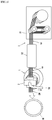
- FIG.5 is a schematic diagram showing a configuration of a conventional bead manufacturing device.
- Wire W is sent from the unwinding device 31 of the wire feeder 3, and then, after being heated by the wire heater 32, it is inserted through the extrusion head 2 attached to the extruder 1.
- a rubber supplied via the extruder 1 is coated on the surface of the wire W to process a linear single bead BW. Thereafter, it is wound by a winder, then formed into an annular shape to produce a bead B (creel bead).
- the spew rubber already has subjected to thermal history, the scorch time becomes shortened.
- the rubber becomes one of factors that the rubber is not coated sufficiently and a bead with rubber peeling is formed. Therefore, in recent years, aiming to improve tire performance further, it is required not to use the spew rubber as reuse rubber, and the spew rubber is discarded.
- an object of the present invention is to provide a rubber-coated cord manufacturing technique that can prevent occurrence of spew rubber during the manufacturing process for a rubber-coated cord and reduce the disposal as scrap, as well as, reduce the burden on operator and stably produce a high quality rubber-coated cord.
- the invention according to claim 1 is, a rubber-coated cord manufacturing device for manufacturing a rubber-coated cord by coating a rubber on a cord, which comprises a screw rotation type extruder for extruding the rubber; an extrusion head for coating the rubber on the surface of the cord, which has an insertion port into which the cord is inserted and a flow path of the rubber extruded from the extruder; a cord supply device for supplying the cord to the extrusion head; a rubber-coated cord winding device for winding the rubber-coated cord coated by the extrusion head; and a head pressure controller for controlling the head pressure of the extrusion head; wherein the head pressure controller controls the head pressure to maintain it at a predetermined pressure by monitoring the head pressure, feeding back the results of monitoring to the extruder and adjusting the rotation speed of the screw during the working of coating the rubber to the cord.
- the invention according to claim 2 is, the rubber-coated cord manufacturing device characterized in that the rubber-coated cord is a bead.
- the invention according to claim 3 is, the rubber-coated cord manufacturing device according to claim 1 or claim 2, characterized in that the head pressure controller is a device for controlling the head pressure by PI control.
- the invention according to claim 4 is, the rubber-coated cord manufacturing device according to any one of claims 1 to 3, which further comprises a cord rate controller for controlling the rate of supplying the cord to the insertion port of the extrusion head to a predetermined rate.
- the invention according to claim 5 is, a rubber-coated cord manufacturing method for manufacturing a rubber-coated cord by forming a rubber coating on surface of a cord with a rubber-coated cord manufacturing device according to any one of claims 1 to 4, which comprises a rubber supply step of supplying the rubber to the extrusion head with a screw rotation type extruder; a cord insertion step of inserting the cord into the insertion port of the extrusion head; a rubber-coated cord processing step of processing a rubber-coated cord by coating the rubber extruded from the extruder on the surface of the inserted cord; and a rubber-coated cord winding step of winding the processed rubber-coated cord, wherein the head pressure of the extrusion head is controlled to maintain at a predetermined pressure by monitoring the head pressure of the extrusion head with the head pressure controller, feeding back the results of monitoring to the extruder and adjusting the rotation speed of the screw during the rubber-coated cord processing step.
- the invention according to claim 6 is, the rubber-coated cord manufacturing method according to claim 5, wherein the head pressure is controlled within a range of 8-12 MPa with the head pressure controller when coating the rubber on the surface of the cord.
- the invention according to claim 7 is, the rubber-coated cord manufacturing method according to claim 5 or claim 6, wherein a rubber-coated cord manufacturing device according to claim 4 is used, and the feed rate of the cord is controlled to a constant rate with the cord rate controller.
- a rubber-coated cord manufacturing technique wherein occurrence of spew rubber is prevented during the rubber-coated cord manufacturing process and disposal as scrap is reduced, as well as, the burden on the operator is reduced and a high quality rubber-coated cord can be produced stably.
- the rubber-coated cord manufacturing device comprises a screw rotation type extruder for extruding rubber, an extrusion head for coating the rubber on surface of a cord and having an inserted port where the cord is inserted and a flow path of the rubber, a cord supply device to supply the cord to the extrusion head, and a rubber-coated cord winding device for winding the rubber-coated cord where the rubber is coated.
- a screw rotation type extruder for extruding rubber
- an extrusion head for coating the rubber on surface of a cord and having an inserted port where the cord is inserted and a flow path of the rubber
- a cord supply device to supply the cord to the extrusion head
- a rubber-coated cord winding device for winding the rubber-coated cord where the rubber is coated.
- it is the same as the conventional rubber-coated cord manufacturing device.
- the extrusion head does not have a relief valve for discharging the spew rubber, and the state is a substantially closed state during operation of coating the rubber to the cord to produce a rubber-coated cord.
- the present embodiment is different from the conventional rubber-coated cord manufacturing device in point that, during the coating to manufacture a rubber-coated cord, the head pressure is always monitored and the monitoring result is fed back to the extruder to adjust the rotation speed of the screw of the extruder in order to maintain the head pressure at a predetermined pressure.
- the present inventors have intensively studied, and, as a result, it was found that, when a head pressure controller for controlling the head pressure of the extrusion head is provided in a screw rotation type extruder (an extruder sending the inserted rubber toward the extrusion head by rotation of a screw) conventionally used in the production of rubber-coated cord, the head pressure is constantly monitored during the working for coating the rubber to the cord, and the rotation speed of the screw is adjusted based on results of the monitoring, the head pressure can be maintained constant, the discharge amount of the rubber can be adequately controlled, and a good rubber coating can be performed, without occurrence of spew rubber from the extrusion head in a sealed state.
- the present invention is explained taking, as an example, a bead manufacturing device for manufacturing a bead by coating a rubber to a wire, which is an example of a rubber-coated cord manufacturing device.
- the head pressure controller which is a characteristic portion of the bead manufacturing device according to this embodiment, will be explained.
- FIG.1 is a schematic view showing a configuration of a bead manufacturing device according to this embodiment.
- 1 is an extruder
- 2 is an extrusion head attached to the extrusion port 13 of the extruder
- 3 is a wire feeder (cord feeder)
- 4 is a bead winding device (rubber-coated cord winding device).
- 5 is a head pressure controller
- 6 is a wire rate controller (cord rate control means).
- the head pressure controller 5 has a head pressure control mechanism and a head pressure fluctuation suppressing mechanism, although they are not shown.
- 22a and 22b are the insertion ports for inserting the wire W (cord) to the extrusion head, and they are a carry-in entrance and a carry-out port, respectively.
- a screw rotation type extruder is used as the extruder 1.
- Extruder 1 of screw rotation type extrudes the rubber G put into the extruder 1 toward the extrusion head 2 by rotating the screw 12 in the cylinder 11 by driving the motor M.
- the extrusion head 2 is kept at a substantially sealed state during the working of coating the rubber to the wire.
- the head pressure controller 5 measures (monitors) the head pressure with the pressure sensor 51 provided inside the extrusion head (rubber flow path 21), and feeds back the result of monitoring to the extruder 1.
- the rubber discharge amount is reduced in order to lower the head pressure to the predetermined pressure by lowering the rotation speed of the motor M, i.e. the rotation speed of the screw 12.
- the discharge amount of rubber is increased in order to increase the head pressure to the predetermined pressure by raising the rotation speed of the motor M, i.e. the rotation speed of the screw 12.
- the rubber can be appropriately coated by maintaining the head pressure at 8-12 MPa. If it is less than 8MPa, supply amount of the rubber to the extrusion head is insufficient, a bead with rubber peeling is formed and a quality problem occurs. On the other hand, if it exceeds 12MPa, supply amount of the rubber to the extrusion head becomes excessive, load on the extruder becomes higher, and a problem that the durability of the extruder is impaired occurs. Maintaining the head pressure at 9-11MPa is more preferably.
- bead production is conventionally generally performed in a multiple line operation wherein the rubber is simultaneously coated to each of the plurality of wire Ws in one extruder, as shown in FIG. 5 .
- a proportional control method has been used where the extrusion rate is increased in proportion to the number of working lines.
- the proportional control method there is a problem, on approaching the target value, the correction amount becomes less and quick modification becomes impossible.
- PI Proportional-Integral control
- the PI control is a control method to eliminate the difference from the target value by making correction to the head pressure based on the integral of the difference between the head pressure and the target value (the sum of the residual), and, therefore, it can cope with the rate change in line quickly. Further, it is possible to reduce the variation with respect to the target pressure value. As a result, while maintaining the head pressure at a constant pressure, a bead can be produced more stably without occurrence of spew rubber.
- FIG.2A is a schematic front view of an extruder of the bead manufacturing device according to the present embodiment
- FIG.2B is a schematic plan view.
- the extrusion head 2 is provided with a cylindrical rubber flow path 21 connected to the extrusion port 13 of the extruder 1, thereby, variation in the head pressure can be suppressed sufficiently to maintain the head pressure at a constant pressure.
- the bead manufacturing device is preferably provided with a wire rate controller (not shown) for controlling the rate of supplying wire W to the insertion port of the extrusion head 2 to a predetermined rate.
- a wire rate controller (not shown) for controlling the rate of supplying wire W to the insertion port of the extrusion head 2 to a predetermined rate.
- the coating can be performed by supplying a rubber in a stable head pressure to the wire sent at a constant rate.
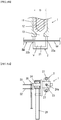
- FIG.3A , 3B, and 3C are, respectively, a schematic front view, a left side schematic view, and a right side schematic view of the extrusion head of the bead manufacturing device according to this embodiment.
- 3 and 23 are rubber discharge ports
- 24 is an open/close valve
- 24a is a valve hole
- 25 is an indication plate for indicating direction of the valve hole, i.e. the opening and closing of the open/close valve 24.
- 26 is a handle for opening and closing the open/close valve 24
- S1 and S2 are proximity sensors.
- 27 is a bolt for fixing the extrusion head 2 to the extruder 1.
- a rubber discharge port 23 connecting to the rubber flow path 21 is provided. Also, a rotatable open/close valve 24 for closing the rubber discharge port 23 is inserted, and a handle 26 is mounted at one end of the open/close valve 24 to rotate the open/close valve 24.
- a valve hole 24a is provided in the open/close valve 24. As shown in FIG.3C , when the valve hole 24a is oriented perpendicularly to the rubber discharge port 23, the open/close valve 24 is in a close state, whereas, when facing in the same direction, the open/close valve 24 is in an open state.
- the handle 26 is pivotable 90 °, and the open/close valve 24 is open by turning the direction of the handle 26 in a substantially horizontal direction and is close by turning it in a substantially vertical direction.
- an indication plate 25 which pivots according to rotation angle of the open/close valve 24. Orientation of the valve hole 24a is indicated by the direction of the indication plate 25, and opening or closing of the valve 24 is detected by the proximity sensor S1, S2 provided in the vicinity of the indication plate 25.
- the open/close valve 24 is determined to be in the open state, when the proximity sensor S1 is detected and the rubber in the extrusion head is discharged to the outside from the open/close valve 24 in the open state.
- the open/close valve 24 is determined to be in the close state, when the proximity sensor S2 is detected.
- the proximity sensor S2 is connected to the head pressure controller 5, and the head pressure controller 5 starts when the open/close valve 24 is determined to be in the close state.
- FIG.4 is a schematic plan view of the extruder of the bead manufacturing device according to another embodiment.
- 21a is a backbone rubber flow path
- 21b is a branched rubber flow path
- 28 is a cap.
- each branched rubber flow path 21b has an openable and closable open/close valve 24, as well as, a cap 28 having an insertion port of the wire W is provided to the downstream side of the each open/close valve 24.
- the wire feeder 3, a bead winding device 4 and the wire rate controller 6 are provided corresponding to each branched rubber flow path 21b.
- the pressure sensor 51 (see FIG.1 ) is attached to the backbone rubber flow path 21a, and is connected to the head pressure controller 5 (see FIG.1 ).
- the extrusion head 2 is substantially sealed, and, as the embodiment described above, a means for head pressure stabilization consisting of a head pressure control mechanism and a head pressure fluctuation suppressing mechanism is provided.
- the head pressure is controlled to 8-12 MPa, more preferably 9-11 MPa, using a head pressure controller 5, based on the measurement result of the monitoring.
- the rate of occurrence of rubber peeling can be suppressed lower without causing harmful equipment such as extruder stop due to the head pressure abnormality, and a bead of good quality can be produced stably.
- the wire is sent towards the extrusion head under a constant rate using the wire rate controller 6 (cord rate controller).
- the rate of consumption of rubber can be maintained constant, and a bead of good quality can be produced more stably, together with the proper maintenance of head pressure.
- the rubber diameter of the bead can be kept suitably and stably, since the coating of rubber is performed while sending the wire at a constant rate.
- the effects of the bead manufacturing device and the bead manufacturing method of this embodiment are the same as those of the rubber-coated cord manufacturing device and the rubber-coated cord manufacturing method.
- the cord in addition to the steel wire, a cord of other metals, a cord of textiles such as polyester, nylon, aramid or the like, a cord of resin materials, and the like can be mentioned.
- a bead was produced with a process of the present invention by changing the head pressure at 11 levels in the range of 5-15 MPa, and the effects of equipment on the bead manufacturing device were evaluated. In addition, the quality of the manufactured bead was evaluated. Note that, new rubber (VIS: 60, ML: 2.6) was used as the rubber.
- the head pressure during manufacture of the beads was fit within the range of the upper and lower 2MPa around value 10MPa and the rubber was supplied with a stable head pressure, when the rate of supplying the wire into the insertion port of the extrusion head was set at a constant rate using a wire rate controller.
Landscapes
- Engineering & Computer Science (AREA)
- Mechanical Engineering (AREA)
- Manufacturing & Machinery (AREA)
- Textile Engineering (AREA)
- Extrusion Moulding Of Plastics Or The Like (AREA)
- Tyre Moulding (AREA)
Abstract
Description
- The present invention relates to a rubber-coated cord manufacturing device and a rubber-coated cord manufacturing method for manufacturing a rubber-coated cord which is a constituent material of vehicle tires.
- A rubber-coated cord, such as an annular bead, which is a constituent material of vehicle tires, is manufactured by using a wire such as a steel wire or the like, i.e., a cord, as the core, and coating a rubber around the core by a rubber-coated cord manufacturing device such as a bead manufacturing device.
-
FIG.5 is a schematic diagram showing a configuration of a conventional bead manufacturing device. Wire W is sent from theunwinding device 31 of thewire feeder 3, and then, after being heated by thewire heater 32, it is inserted through theextrusion head 2 attached to theextruder 1. Next, in theextrusion head 2, a rubber supplied via theextruder 1 is coated on the surface of the wire W to process a linear single bead BW. Thereafter, it is wound by a winder, then formed into an annular shape to produce a bead B (creel bead). - At the time, in order to sufficiently coat the rubber to the wire W, it is necessary to apply a certain pressure to the rubber to be brought to contact with the wire. Hence, conventionally, a required amount or more of rubber is supplied to the
extrusion head 2 in order to make the head pressure to some extent high. However, if the head pressure is abnormally high, there is a danger that theextrusion head 2 is damaged. Therefore, when the head pressure rises abnormally, the excess rubber is discharged to the outside of theextrusion head 2, as a spew rubber SG from the relief valve provided at theextrusion head 2 in order to prevent the head pressure rising excessively (e.g.,Patent documents 1 and 2). -
- [Patent Document 1]
JP-A-8-47984 - [Patent Document 2]
JP-A-2006-51748 - However, in the conventional production of bead, when the discharged spew rubber SG is wound and recovered then is put into the
extruder 1 as reuse rubber with new rubber at the next bead production, there has been such a problem as follows. - That is, since the spew rubber already has subjected to thermal history, the scorch time becomes shortened. As a result, when using the spew rubber as reuse rubber, the rubber becomes one of factors that the rubber is not coated sufficiently and a bead with rubber peeling is formed. Therefore, in recent years, aiming to improve tire performance further, it is required not to use the spew rubber as reuse rubber, and the spew rubber is discarded.
- Accordingly, an object of the present invention is to provide a rubber-coated cord manufacturing technique that can prevent occurrence of spew rubber during the manufacturing process for a rubber-coated cord and reduce the disposal as scrap, as well as, reduce the burden on operator and stably produce a high quality rubber-coated cord.
- The present inventors have conducted extensive studies for solving the above problems, found that the above problems can be solved by the invention described below, and completed the present invention.
- The invention according to
claim 1 is,
a rubber-coated cord manufacturing device for manufacturing a rubber-coated cord by coating a rubber on a cord,
which comprises
a screw rotation type extruder for extruding the rubber;
an extrusion head for coating the rubber on the surface of the cord, which has an insertion port into which the cord is inserted and a flow path of the rubber extruded from the extruder;
a cord supply device for supplying the cord to the extrusion head;
a rubber-coated cord winding device for winding the rubber-coated cord coated by the extrusion head; and
a head pressure controller for controlling the head pressure of the extrusion head;
wherein
the head pressure controller controls the head pressure to maintain it at a predetermined pressure by monitoring the head pressure, feeding back the results of monitoring to the extruder and adjusting the rotation speed of the screw during the working of coating the rubber to the cord. - The invention according to
claim 2 is,
the rubber-coated cord manufacturing device characterized in that the rubber-coated cord is a bead. - The invention according to
claim 3 is,
the rubber-coated cord manufacturing device according toclaim 1 orclaim 2, characterized in that the head pressure controller is a device for controlling the head pressure by PI control. - The invention according to
claim 4 is,
the rubber-coated cord manufacturing device according to any one ofclaims 1 to 3,
which further comprises a cord rate controller for controlling the rate of supplying the cord to the insertion port of the extrusion head to a predetermined rate. - The invention according to
claim 5 is,
a rubber-coated cord manufacturing method for manufacturing a rubber-coated cord by forming a rubber coating on surface of a cord with a rubber-coated cord manufacturing device according to any one ofclaims 1 to 4,
which comprises
a rubber supply step of supplying the rubber to the extrusion head with a screw rotation type extruder;
a cord insertion step of inserting the cord into the insertion port of the extrusion head;
a rubber-coated cord processing step of processing a rubber-coated cord by coating the rubber extruded from the extruder on the surface of the inserted cord; and
a rubber-coated cord winding step of winding the processed rubber-coated cord,
wherein
the head pressure of the extrusion head is controlled to maintain at a predetermined pressure by monitoring the head pressure of the extrusion head with the head pressure controller, feeding back the results of monitoring to the extruder and adjusting the rotation speed of the screw during the rubber-coated cord processing step. - The invention according to claim 6 is,
the rubber-coated cord manufacturing method according toclaim 5,
wherein the head pressure is controlled within a range of 8-12 MPa with the head pressure controller when coating the rubber on the surface of the cord. - The invention according to claim 7 is,
the rubber-coated cord manufacturing method according toclaim 5 or claim 6, wherein
a rubber-coated cord manufacturing device according toclaim 4 is used, and
the feed rate of the cord is controlled to a constant rate with the cord rate controller. - According to the present invention, can be provided a rubber-coated cord manufacturing technique, wherein occurrence of spew rubber is prevented during the rubber-coated cord manufacturing process and disposal as scrap is reduced, as well as, the burden on the operator is reduced and a high quality rubber-coated cord can be produced stably.
-
- [
FIG.1 ] is a schematic view showing a configuration of a bead manufacturing device according to an embodiment of the present invention. - [
FIG.2A ] is a schematic front view of an extruder of a bead manufacturing device according to an embodiment of the present invention. - [
FIG. 2B ] is a schematic plan view of the extruder of the bead manufacturing device according to an embodiment of the present invention. - [
FIG. 3A ] is a schematic front view of an extrusion head of a bead manufacturing device according to an embodiment of the present invention. - [
FIG. 3B ] is a left side schematic view of the extrusion head of the bead manufacturing device according to an embodiment of the present invention. - [
FIG. 3C ] is a right side schematic view of the extrusion head of the bead manufacturing device according to an embodiment of the present invention. - [
FIG. 4 ] is a schematic plan view of an extruder of a bead manufacturing device according to another embodiment of the present invention. - [
FIG. 5 ] is a schematic view showing a configuration of a conventional bead manufacturing device. - Hereinafter, based on embodiments, the present invention will be described with reference to drawings.
- First, an overview of the rubber-coated cord manufacturing device according to this embodiment is explained.
- The rubber-coated cord manufacturing device according to the present embodiment comprises a screw rotation type extruder for extruding rubber, an extrusion head for coating the rubber on surface of a cord and having an inserted port where the cord is inserted and a flow path of the rubber, a cord supply device to supply the cord to the extrusion head, and a rubber-coated cord winding device for winding the rubber-coated cord where the rubber is coated. In the above respects, it is the same as the conventional rubber-coated cord manufacturing device.
- However, in the present embodiment, the extrusion head does not have a relief valve for discharging the spew rubber, and the state is a substantially closed state during operation of coating the rubber to the cord to produce a rubber-coated cord. The present embodiment is different from the conventional rubber-coated cord manufacturing device in point that, during the coating to manufacture a rubber-coated cord, the head pressure is always monitored and the monitoring result is fed back to the extruder to adjust the rotation speed of the screw of the extruder in order to maintain the head pressure at a predetermined pressure.
- When the extrusion head is in the closed state, as it is, the head pressure increases since there is no escape for rubber. Meanwhile, in order to perform rubber coating free from unevenness such as rubber peeling, as mentioned above, it is necessary to maintain the head pressure high to some extent. Therefore, conventionally, as described above, while supplying the required amount for coating or more of rubber to the extrusion head, an open extrusion head for discharging the excess rubber from the relief valve is provided in order to prevent excessive rise in head pressure.
- Meanwhile, in order to properly control the amount of rubber coated on the cord, it is necessary to appropriately control the discharge amount of the rubber from the extruder. However, it is difficult to control the discharge amount from the rubber extruder by controlling screw rotation speed with a general rubber extruder, because rubber is a viscoelastic body. Therefore, conventionally, the control of the discharge amount has been performed by feeding back the pulling rate of cord after coating and the supply amount of rubber, but it has not been easy yet to suppress the occurrence of spew rubber.
- In contrast, the present inventors have intensively studied, and, as a result, it was found that,
when a head pressure controller for controlling the head pressure of the extrusion head is provided in a screw rotation type extruder (an extruder sending the inserted rubber toward the extrusion head by rotation of a screw) conventionally used in the production of rubber-coated cord, the head pressure is constantly monitored during the working for coating the rubber to the cord, and the rotation speed of the screw is adjusted based on results of the monitoring,
the head pressure can be maintained constant, the discharge amount of the rubber can be adequately controlled, and a good rubber coating can be performed, without occurrence of spew rubber from the extrusion head in a sealed state. In the following, the present invention is explained taking, as an example, a bead manufacturing device for manufacturing a bead by coating a rubber to a wire, which is an example of a rubber-coated cord manufacturing device. - Next, the head pressure controller, which is a characteristic portion of the bead manufacturing device according to this embodiment, will be explained.
-
FIG.1 is a schematic view showing a configuration of a bead manufacturing device according to this embodiment. InFIG.1, 1 is an extruder, 2 is an extrusion head attached to theextrusion port 13 of theextruder head pressure controller 5 has a head pressure control mechanism and a head pressure fluctuation suppressing mechanism, although they are not shown. Note that, 22a and 22b are the insertion ports for inserting the wire W (cord) to the extrusion head, and they are a carry-in entrance and a carry-out port, respectively. - In
FIG.1 , a screw rotation type extruder is used as theextruder 1.Extruder 1 of screw rotation type extrudes the rubber G put into theextruder 1 toward theextrusion head 2 by rotating thescrew 12 in thecylinder 11 by driving the motor M. - In this embodiment, as described above, the
extrusion head 2 is kept at a substantially sealed state during the working of coating the rubber to the wire. Under this sealed state, thehead pressure controller 5 measures (monitors) the head pressure with thepressure sensor 51 provided inside the extrusion head (rubber flow path 21), and feeds back the result of monitoring to theextruder 1. - Specifically, if the head pressure is monitored to be in a rising trend, the rubber discharge amount is reduced in order to lower the head pressure to the predetermined pressure by lowering the rotation speed of the motor M, i.e. the rotation speed of the
screw 12. On the other hand, if it is monitored that the head pressure is in the downward trend, the discharge amount of rubber is increased in order to increase the head pressure to the predetermined pressure by raising the rotation speed of the motor M, i.e. the rotation speed of thescrew 12. Thus, in a state where the head pressure was maintained at a constant pressure, a bead can be produced stably without occurrence of spew rubber. - Specifically, the rubber can be appropriately coated by maintaining the head pressure at 8-12 MPa. If it is less than 8MPa, supply amount of the rubber to the extrusion head is insufficient, a bead with rubber peeling is formed and a quality problem occurs. On the other hand, if it exceeds 12MPa, supply amount of the rubber to the extrusion head becomes excessive, load on the extruder becomes higher, and a problem that the durability of the extruder is impaired occurs. Maintaining the head pressure at 9-11MPa is more preferably.
- Note that, bead production is conventionally generally performed in a multiple line operation wherein the rubber is simultaneously coated to each of the plurality of wire Ws in one extruder, as shown in
FIG. 5 . In such a case, conventionally, a proportional control method has been used where the extrusion rate is increased in proportion to the number of working lines. However, in the proportional control method, there is a problem, on approaching the target value, the correction amount becomes less and quick modification becomes impossible. - In contrast, in the present embodiment, PI (Proportional-Integral) control is introduced in the pressure control method for controlling the head pressure. The PI control is a control method to eliminate the difference from the target value by making correction to the head pressure based on the integral of the difference between the head pressure and the target value (the sum of the residual), and, therefore, it can cope with the rate change in line quickly. Further, it is possible to reduce the variation with respect to the target pressure value. As a result, while maintaining the head pressure at a constant pressure, a bead can be produced more stably without occurrence of spew rubber.
-
FIG.2A is a schematic front view of an extruder of the bead manufacturing device according to the present embodiment, andFIG.2B is a schematic plan view. As shown inFIG.2 , theextrusion head 2 is provided with a cylindricalrubber flow path 21 connected to theextrusion port 13 of theextruder 1, thereby, variation in the head pressure can be suppressed sufficiently to maintain the head pressure at a constant pressure. - Further, the bead manufacturing device according to this embodiment is preferably provided with a wire rate controller (not shown) for controlling the rate of supplying wire W to the insertion port of the
extrusion head 2 to a predetermined rate. Thus, the coating can be performed by supplying a rubber in a stable head pressure to the wire sent at a constant rate. - In bead production line, there may be a case that the line stops for a long time. At this time, if the rubber is left retained in the extrusion head for a long time, a burning rubber is produced by the thermal history. In the conventional bead manufacturing device, the spew rubber SG is discharged from a discharge port so as not to retain the rubber in the extrusion head. However, since there is no discharge port in bead manufacturing device according to this embodiment, it is preferable to provide a burn rubber occurrence prevention means described below in case of the line stops for a long time.
- Hereinafter, a specific burnt rubber occurrence prevention means will be explained.
FIG.3A ,3B, and 3C are, respectively, a schematic front view, a left side schematic view, and a right side schematic view of the extrusion head of the bead manufacturing device according to this embodiment. InFIG.3 , 3 and 23 are rubber discharge ports, 24 is an open/close valve, 24a is a valve hole, 25 is an indication plate for indicating direction of the valve hole, i.e. the opening and closing of the open/close valve 24. Then, 26 is a handle for opening and closing the open/close valve 24, and S1 and S2 are proximity sensors. Incidentally, 27 is a bolt for fixing theextrusion head 2 to theextruder 1. - At the
extrusion head 2, arubber discharge port 23 connecting to therubber flow path 21 is provided. Also, a rotatable open/close valve 24 for closing therubber discharge port 23 is inserted, and ahandle 26 is mounted at one end of the open/close valve 24 to rotate the open/close valve 24. Avalve hole 24a is provided in the open/close valve 24. As shown inFIG.3C , when thevalve hole 24a is oriented perpendicularly to therubber discharge port 23, the open/close valve 24 is in a close state, whereas, when facing in the same direction, the open/close valve 24 is in an open state. - Specifically, as shown in
FIG.3B , thehandle 26 is pivotable 90 °, and the open/close valve 24 is open by turning the direction of thehandle 26 in a substantially horizontal direction and is close by turning it in a substantially vertical direction. At one end of the open/close valve 24, is attached anindication plate 25 which pivots according to rotation angle of the open/close valve 24. Orientation of thevalve hole 24a is indicated by the direction of theindication plate 25, and opening or closing of thevalve 24 is detected by the proximity sensor S1, S2 provided in the vicinity of theindication plate 25. - That is, the open/
close valve 24 is determined to be in the open state, when the proximity sensor S1 is detected and the rubber in the extrusion head is discharged to the outside from the open/close valve 24 in the open state. On the other hand, the open/close valve 24 is determined to be in the close state, when the proximity sensor S2 is detected. Incidentally, the proximity sensor S2 is connected to thehead pressure controller 5, and thehead pressure controller 5 starts when the open/close valve 24 is determined to be in the close state. -
FIG.4 is a schematic plan view of the extruder of the bead manufacturing device according to another embodiment. InFIG.4 , 21a is a backbone rubber flow path, 21b is a branched rubber flow path and 28 is a cap. - In this embodiment, each branched
rubber flow path 21b has an openable and closable open/close valve 24, as well as, acap 28 having an insertion port of the wire W is provided to the downstream side of the each open/close valve 24. Further, thewire feeder 3, abead winding device 4 and the wire rate controller 6 (seeFIG.1 ) are provided corresponding to each branchedrubber flow path 21b. The pressure sensor 51 (seeFIG.1 ) is attached to the backbonerubber flow path 21a, and is connected to the head pressure controller 5 (seeFIG.1 ). Thus, a plurality of beads can be produced simultaneously and beads can be produced efficiently. - Also in the bead manufacturing device of this embodiment, the
extrusion head 2 is substantially sealed, and, as the embodiment described above, a means for head pressure stabilization consisting of a head pressure control mechanism and a head pressure fluctuation suppressing mechanism is provided. - Hereinafter, the characteristic portions among the rubber-coated cord manufacturing method according to the present embodiment will be explained. In the following, a bead manufacturing method, which is an example of the rubber-coated cord manufacturing method, will be explained as an example.
- In this embodiment, during the working of coating rubber to the wire, the head pressure is controlled to 8-12 MPa, more preferably 9-11 MPa, using a
head pressure controller 5, based on the measurement result of the monitoring. Thus, the rate of occurrence of rubber peeling can be suppressed lower without causing harmful equipment such as extruder stop due to the head pressure abnormality, and a bead of good quality can be produced stably. - During the working of coating rubber to the wire (cord), the wire is sent towards the extrusion head under a constant rate using the wire rate controller 6 (cord rate controller). Thus, the rate of consumption of rubber can be maintained constant, and a bead of good quality can be produced more stably, together with the proper maintenance of head pressure. In addition, the rubber diameter of the bead can be kept suitably and stably, since the coating of rubber is performed while sending the wire at a constant rate.
- Conventionally, there has been a case that a bead with rubber peeling was produced, since a spew rubber in which the VIS (Mooney viscosity) and ML (modulus) lowered is used as the reuse rubber and mixed with new rubber to use. Meanwhile, in this embodiment, since spew rubber does not occur, new rubber is always used for the coating of rubber. Therefore, there is no such case as the VIS and ML of the coated rubber lowered, and a bead of high quality can be produced and provided stably.
- Following, the effects of the present embodiment will be described.
- 1. In the present embodiment, the rubber-coated cord is produced by adjusting the extrusion amount of the rubber by adjusting the rotation speed of the screw with the head pressure controller, while the head pressure of the extrusion head which is in a closed state is maintained at an appropriate pressure with high precision. As a result, a good rubber coating can be performed without occurrence of spew rubber and a rubber-coated cord of good quality can be produced stably.
- 2. Since no spew rubber SG occurs, the amount of rubber to be discarded as scrap is reduced significantly, along with it, it is possible to greatly reduce the costs associated with disposal of rubber.
- 3. Furthermore, since no spew rubber SG occurs, the discharge amount of rubber by the extruder can be reduced than conventional technology. As a result, rotation speed of the screw of the extruder can also be reduced, thereby the progress of wear can be suppressed and it is possible to extend the life of the extruder.
- The effects of the bead manufacturing device and the bead manufacturing method of this embodiment are the same as those of the rubber-coated cord manufacturing device and the rubber-coated cord manufacturing method. Note that, as the cord, in addition to the steel wire, a cord of other metals, a cord of textiles such as polyester, nylon, aramid or the like, a cord of resin materials, and the like can be mentioned.
- Hereinafter, the present invention will be explained more specifically based on examples. In the examples, the experiments are conducted by using a bead manufacturing device which is an example of a rubber-coated cord manufacturing device.
- In
Experiment 1, a bead was produced with a process of the present invention by changing the head pressure at 11 levels in the range of 5-15 MPa, and the effects of equipment on the bead manufacturing device were evaluated. In addition, the quality of the manufactured bead was evaluated. Note that, new rubber (VIS: 60, ML: 2.6) was used as the rubber. - The evaluation results are shown in Table 1.
[Table 1] Head pressure (MPa) Re. Quality Re. Equipment 15 - No evaluation Abnormal head pressure Extruder stopped 14 - No evaluation Abnormal head pressure Extruder stopped 13 - No evaluation Abnormal head pressure Extruder stopped 12 Possible Rubber peeling rate 5% or lessNo problem 11 Good No rubber peeling No problem 10 Good No rubber peeling No problem 9 Good No rubber peeling No problem 8 Possible Rubber peeling rate 5% or lessNo problem 7 Impossible Rubber peeling rate 20% or more No problem 6 Impossible Rubber peeling rate: 20% or more No problem 5 Impossible Rubber peeling rate 20% or more No problem - As shown in Table 1, in the case of setting the head pressure at 13MPa or above, abnormal head pressure occurs, and it was not possible to produce a bead, because the extruder stopped. On the other hand, in the case of setting the head pressure at 12MPa or below, it was possible to produce a bead without abnormalities of equipment.
- On the other hand, while, in the case of setting the head pressure at 7MPa or below, the rubber peeling rate was 20% or more, and quality of the bead was "impossible", in the case of setting the head pressure in the range of 8-12 MPa, rubber peeling rate was 5% or less, i.e. the quality turned into good. Inter alia, when the head pressure was set within a range of 9-11 MPa, no rubber peeling occurred and the quality was "good".
- In
Experiment 2, it was confirmed the effect of controlling the rate of supplying the wire into the insertion port of the extrusion head to a predetermined rate (constant rate). - Specifically, it was confirmed that the head pressure during manufacture of the beads was fit within the range of the upper and lower 2MPa around value 10MPa and the rubber was supplied with a stable head pressure, when the rate of supplying the wire into the insertion port of the extrusion head was set at a constant rate using a wire rate controller.
- Although the present invention has been explained based on the embodiments, the present invention is not limited to the above embodiment. Within the scope of the same as or equivalent to the present invention, various modifications to the above embodiment can be made.
-
- 1
- extruder
- 2
- extrusion head
- 3
- wire feeder
- 4
- bead winding device
- 5
- head pressure controller
- 6
- wire rate controller
- 11
- cylinder
- 12
- screw
- 13
- extrusion port
- 21
- rubber flow path
- 21a
- backbone rubber flow path
- 21b
- branched rubber flow path
- 22a
- carry-in entrance
- 22b
- carry-out port
- 23
- rubber discharge port
- 24
- open/close valve
- 24a
- valve hole
- 25
- indication plate
- 26
- handle
- 27
- bolt
- 28
- cap
- 31
- unwinding device
- 32
- wire heater
- 51
- pressure sensor
- B
- bead (creel bead)
- BW
- single bead
- D
- screw diameter
- G
- rubber
- M
- motor
- S1, S2
- proximity sensor
- SG
- spew rubber
- V
- rubber flow path volume
- W
- wire
Claims (7)
- A rubber-coated cord manufacturing device for manufacturing a rubber-coated cord by coating a rubber on a cord,
which comprises
a screw rotation type extruder for extruding the rubber;
an extrusion head for coating the rubber on the surface of the cord, which has an insertion port into which the cord is inserted and a flow path of the rubber extruded from the extruder;
a cord supply device for supplying the cord to the extrusion head;
a rubber-coated cord winding device for winding the rubber-coated cord coated by the extrusion head; and
a head pressure controller for controlling the head pressure of the extrusion head;
wherein
the head pressure controller controls the head pressure to maintain it at a predetermined pressure by monitoring the head pressure, feeding back the results of monitoring to the extruder and adjusting the rotation speed of the screw during the working of coating the rubber to the cord. - The rubber-coated cord manufacturing device characterized in that the rubber-coated cord is a bead.
- The rubber-coated cord manufacturing device according to claim 1 or claim 2, characterized in that the head pressure controller is a device for controlling the head pressure by PI control.
- The rubber-coated cord manufacturing device according to any one of claims 1 to 3,
which further comprises a cord rate controller for controlling the rate of supplying the cord to the insertion port of the extrusion head to a predetermined rate. - A rubber-coated cord manufacturing method for manufacturing a rubber-coated cord by forming a rubber coating on surface of a cord with a rubber-coated cord manufacturing device according to any one of claims 1 to 4,
which comprises
a rubber supply step of supplying the rubber to the extrusion head with a screw rotation type extruder;
a cord insertion step of inserting the cord into the insertion port of the extrusion head;
a rubber-coated cord processing step of processing a rubber-coated cord by coating the rubber extruded from the extruder on the surface of the inserted cord; and
a rubber-coated cord winding step of winding the processed rubber-coated cord,
wherein
the head pressure of the extrusion head is controlled to maintain at a predetermined pressure by monitoring the head pressure of the extrusion head with the head pressure controller, feeding back the results of monitoring to the extruder and adjusting the rotation speed of the screw during the rubber-coated cord processing step. - The rubber-coated cord manufacturing method according to claim 5,
wherein the head pressure is controlled within a range of 8-12 MPa with the head pressure controller when coating the rubber on the surface of the cord. - The rubber-coated cord manufacturing method according to claim 5 or claim 6, wherein
a rubber-coated cord manufacturing device according to claim 4 is used, and
the feed rate of the cord is controlled to constant rate with the cord rate controller.
Applications Claiming Priority (2)
| Application Number | Priority Date | Filing Date | Title |
|---|---|---|---|
| JP2018074679 | 2018-04-09 | ||
| PCT/JP2019/013954 WO2019198544A1 (en) | 2018-04-09 | 2019-03-29 | Rubber-coated cord manufacturing device and rubber-coated cord manufacturing method |
Publications (2)
| Publication Number | Publication Date |
|---|---|
| EP3763507A1 true EP3763507A1 (en) | 2021-01-13 |
| EP3763507A4 EP3763507A4 (en) | 2021-12-08 |
Family
ID=68163724
Family Applications (1)
| Application Number | Title | Priority Date | Filing Date |
|---|---|---|---|
| EP19785503.4A Withdrawn EP3763507A4 (en) | 2018-04-09 | 2019-03-29 | Rubber-coated cord manufacturing device and rubber-coated cord manufacturing method |
Country Status (5)
| Country | Link |
|---|---|
| US (1) | US20210008782A1 (en) |
| EP (1) | EP3763507A4 (en) |
| JP (1) | JP7237284B2 (en) |
| CN (1) | CN111936292A (en) |
| WO (1) | WO2019198544A1 (en) |
Families Citing this family (5)
| Publication number | Priority date | Publication date | Assignee | Title |
|---|---|---|---|---|
| JP7456297B2 (en) | 2020-06-02 | 2024-03-27 | 住友ゴム工業株式会社 | Rubber coating equipment and its coating head |
| JP7614490B2 (en) | 2021-01-28 | 2025-01-16 | 横浜ゴム株式会社 | Manufacturing method and apparatus for rubber-coated wire |
| CN113001930B (en) * | 2021-02-22 | 2022-10-25 | 重庆市九龙橡胶制品制造有限公司 | High-strength canvas rubber belt extrusion equipment |
| CN114985501B (en) * | 2022-08-01 | 2022-10-21 | 天津赛象科技股份有限公司 | Multi-specification steel wire ring processing production line |
| CN116749513B (en) * | 2023-07-10 | 2024-11-22 | 南通鹏宝运动用品有限公司 | Additive powder spraying device for rubber-coated dumbbells |
Family Cites Families (16)
| Publication number | Priority date | Publication date | Assignee | Title |
|---|---|---|---|---|
| JPH02150340A (en) * | 1988-11-30 | 1990-06-08 | Sumitomo Rubber Ind Ltd | Apparatus for rubber coating and liner connecting |
| JPH02269024A (en) * | 1989-04-11 | 1990-11-02 | Toyoda Gosei Co Ltd | Apparatus for control of emission amount of extruder with gear pump |
| CA2033453A1 (en) * | 1990-12-31 | 1992-07-01 | Masakazu Yamauchi | Apparatus for rubber coating of cords |
| JP2813475B2 (en) * | 1991-01-29 | 1998-10-22 | 三菱重工業株式会社 | Method for controlling the output of a tandem extruder |
| CA2097642A1 (en) * | 1993-03-19 | 1994-09-20 | Jerry Malin | Method and apparatus for fabricating a rubberized wire sheet |
| JPH0847984A (en) * | 1994-08-08 | 1996-02-20 | Bridgestone Corp | Bead manufacturing apparatus |
| JP4818504B2 (en) * | 2000-10-12 | 2011-11-16 | 株式会社ブリヂストン | Belt cord rubber coating equipment |
| WO2004030899A1 (en) * | 2002-10-01 | 2004-04-15 | Bridgestone Corporation | Method and apparatus for forming cord reinforcement layer for tire |
| JP2005262672A (en) * | 2004-03-18 | 2005-09-29 | Sumitomo Rubber Ind Ltd | Steel cord ply manufacturing method, steel cord ply and pneumatic tire using the same |
| JP2006051748A (en) | 2004-08-16 | 2006-02-23 | Sumitomo Rubber Ind Ltd | Bead manufacturing equipment |
| JP2006150620A (en) * | 2004-11-25 | 2006-06-15 | Bridgestone Corp | Rubber extrusion method for preventing stagnation and temperature rise of rubber |
| US20070122605A1 (en) * | 2005-11-30 | 2007-05-31 | Downing Daniel R | Apparatus and method of manufacturing reduced gauge tire ply |
| NL1033470C2 (en) * | 2007-03-01 | 2008-09-02 | Vmi Epe Holland | Device for making a belt layer. |
| EP1997607B1 (en) * | 2007-05-31 | 2011-03-23 | Société de Technologie Michelin | Device and method for insulating a set of yarns |
| SK7309Y1 (en) * | 2014-09-03 | 2015-12-03 | Konstrukta Industry A S | Apparatus for controlling the parameters of the coating heads of reinforcing fibers |
| NL2014634B1 (en) * | 2015-04-14 | 2016-12-20 | Vmi Holland Bv | Extruder system for extruding cord reinforced extrudate. |
-
2019
- 2019-03-29 EP EP19785503.4A patent/EP3763507A4/en not_active Withdrawn
- 2019-03-29 WO PCT/JP2019/013954 patent/WO2019198544A1/en not_active Ceased
- 2019-03-29 US US16/980,608 patent/US20210008782A1/en not_active Abandoned
- 2019-03-29 JP JP2019557656A patent/JP7237284B2/en active Active
- 2019-03-29 CN CN201980024345.1A patent/CN111936292A/en not_active Withdrawn
Also Published As
| Publication number | Publication date |
|---|---|
| WO2019198544A1 (en) | 2019-10-17 |
| EP3763507A4 (en) | 2021-12-08 |
| JPWO2019198544A1 (en) | 2021-03-11 |
| US20210008782A1 (en) | 2021-01-14 |
| JP7237284B2 (en) | 2023-03-13 |
| CN111936292A (en) | 2020-11-13 |
Similar Documents
| Publication | Publication Date | Title |
|---|---|---|
| US20210008782A1 (en) | Rubber-coated cord manufacturing device and rubber-coated cord manufacturing method | |
| CN102529061B (en) | For the extruder device of forming tire components | |
| CN109513570B (en) | Coating head, coating device and coating method | |
| EP3393747B1 (en) | Extrusion device and process for extruding a semi-finished product made of elastomeric material | |
| WO2009027519A4 (en) | Process for purging an extrusion apparatus | |
| US20050189061A1 (en) | Method of and apparatus for forming rubber strip materials for building tires and method of building tires | |
| CN115816692A (en) | Granulation production system of degradable plastics | |
| US20120267038A1 (en) | Rubber strip material extrusion method | |
| US20090283203A1 (en) | Process and apparatus for building pneumatic tyres | |
| EP1454732B1 (en) | Production method for unvulcanized rubber member and tire | |
| US8062013B2 (en) | Device for internal cooling of extruded thermoplastics pipes | |
| JPH09504061A (en) | Cellulose solution treatment apparatus and production equipment configuration including the same | |
| KR20190047227A (en) | Automatic control apparatus and control method for extruder and extrusion line speed | |
| US11130302B2 (en) | Bead core coating method and bead core coating apparatus | |
| KR100876437B1 (en) | Green tire vulcanization device and vulcanization method | |
| US20230373147A1 (en) | Method for extruding a semi-finished product made of elastomeric material | |
| JP2987183B2 (en) | Extrusion molding method and apparatus | |
| US8877105B2 (en) | Process for manufacturing elastomeric tire components | |
| CN112172078B (en) | Rubber coating head and rubber coating cord manufacturing device | |
| CN213260965U (en) | Extruder feeding device for PE pipe production | |
| US2638628A (en) | Apparatus for production of strip stock from polyamides | |
| CN102196899A (en) | Process for building tyres | |
| CN109571999B (en) | Plastic composite fiber production equipment capable of automatically balancing pressure | |
| CN220031121U (en) | Glue coating extrusion device | |
| EP2516131B1 (en) | Extrusion process and device for producing elastomeric compounds |
Legal Events
| Date | Code | Title | Description |
|---|---|---|---|
| STAA | Information on the status of an ep patent application or granted ep patent |
Free format text: STATUS: THE INTERNATIONAL PUBLICATION HAS BEEN MADE |
|
| PUAI | Public reference made under article 153(3) epc to a published international application that has entered the european phase |
Free format text: ORIGINAL CODE: 0009012 |
|
| STAA | Information on the status of an ep patent application or granted ep patent |
Free format text: STATUS: REQUEST FOR EXAMINATION WAS MADE |
|
| 17P | Request for examination filed |
Effective date: 20201008 |
|
| AK | Designated contracting states |
Kind code of ref document: A1 Designated state(s): AL AT BE BG CH CY CZ DE DK EE ES FI FR GB GR HR HU IE IS IT LI LT LU LV MC MK MT NL NO PL PT RO RS SE SI SK SM TR |
|
| AX | Request for extension of the european patent |
Extension state: BA ME |
|
| DAV | Request for validation of the european patent (deleted) | ||
| DAX | Request for extension of the european patent (deleted) | ||
| A4 | Supplementary search report drawn up and despatched |
Effective date: 20211108 |
|
| RIC1 | Information provided on ipc code assigned before grant |
Ipc: B29K 21/00 20060101ALN20211102BHEP Ipc: B29D 30/48 20060101ALN20211102BHEP Ipc: B29C 48/25 20190101ALN20211102BHEP Ipc: B29C 48/156 20190101ALI20211102BHEP Ipc: B29C 48/34 20190101ALI20211102BHEP Ipc: B29C 48/92 20190101AFI20211102BHEP |
|
| STAA | Information on the status of an ep patent application or granted ep patent |
Free format text: STATUS: THE APPLICATION IS DEEMED TO BE WITHDRAWN |
|
| 18D | Application deemed to be withdrawn |
Effective date: 20220608 |