EP3763327B1 - Aorta treatment device - Google Patents
Aorta treatment device Download PDFInfo
- Publication number
- EP3763327B1 EP3763327B1 EP18909066.5A EP18909066A EP3763327B1 EP 3763327 B1 EP3763327 B1 EP 3763327B1 EP 18909066 A EP18909066 A EP 18909066A EP 3763327 B1 EP3763327 B1 EP 3763327B1
- Authority
- EP
- European Patent Office
- Prior art keywords
- blood vessel
- artificial blood
- treatment device
- branched artificial
- aorta
- Prior art date
- Legal status (The legal status is an assumption and is not a legal conclusion. Google has not performed a legal analysis and makes no representation as to the accuracy of the status listed.)
- Active
Links
- 210000000709 aorta Anatomy 0.000 title claims description 69
- 210000004204 blood vessel Anatomy 0.000 claims description 105
- 239000002473 artificial blood Substances 0.000 claims description 97
- 239000000463 material Substances 0.000 claims description 18
- 239000011248 coating agent Substances 0.000 claims description 11
- 238000000576 coating method Methods 0.000 claims description 11
- 239000008280 blood Substances 0.000 claims description 8
- 210000004369 blood Anatomy 0.000 claims description 8
- 239000004744 fabric Substances 0.000 description 16
- 229920005992 thermoplastic resin Polymers 0.000 description 11
- 210000002376 aorta thoracic Anatomy 0.000 description 7
- -1 polyethylene Polymers 0.000 description 6
- 239000000835 fiber Substances 0.000 description 5
- 229910052751 metal Inorganic materials 0.000 description 4
- 239000002184 metal Substances 0.000 description 4
- 102000008186 Collagen Human genes 0.000 description 3
- 108010035532 Collagen Proteins 0.000 description 3
- 108010010803 Gelatin Proteins 0.000 description 3
- 230000003872 anastomosis Effects 0.000 description 3
- 229920001436 collagen Polymers 0.000 description 3
- 230000000694 effects Effects 0.000 description 3
- 229920000159 gelatin Polymers 0.000 description 3
- 239000008273 gelatin Substances 0.000 description 3
- 235000019322 gelatine Nutrition 0.000 description 3
- 235000011852 gelatine desserts Nutrition 0.000 description 3
- 238000000034 method Methods 0.000 description 3
- 229920000728 polyester Polymers 0.000 description 3
- 208000007474 aortic aneurysm Diseases 0.000 description 2
- 230000001174 ascending effect Effects 0.000 description 2
- 201000010099 disease Diseases 0.000 description 2
- 208000037265 diseases, disorders, signs and symptoms Diseases 0.000 description 2
- 229920000840 ethylene tetrafluoroethylene copolymer Polymers 0.000 description 2
- NBVXSUQYWXRMNV-UHFFFAOYSA-N fluoromethane Chemical compound FC NBVXSUQYWXRMNV-UHFFFAOYSA-N 0.000 description 2
- PCHJSUWPFVWCPO-UHFFFAOYSA-N gold Chemical compound [Au] PCHJSUWPFVWCPO-UHFFFAOYSA-N 0.000 description 2
- 229910052737 gold Inorganic materials 0.000 description 2
- 239000010931 gold Substances 0.000 description 2
- 238000003780 insertion Methods 0.000 description 2
- 230000037431 insertion Effects 0.000 description 2
- BASFCYQUMIYNBI-UHFFFAOYSA-N platinum Chemical compound [Pt] BASFCYQUMIYNBI-UHFFFAOYSA-N 0.000 description 2
- 229920000139 polyethylene terephthalate Polymers 0.000 description 2
- 239000005020 polyethylene terephthalate Substances 0.000 description 2
- 239000004810 polytetrafluoroethylene Substances 0.000 description 2
- 229920001343 polytetrafluoroethylene Polymers 0.000 description 2
- 229920005989 resin Polymers 0.000 description 2
- 239000011347 resin Substances 0.000 description 2
- 238000001356 surgical procedure Methods 0.000 description 2
- 229910017535 Cu-Al-Ni Inorganic materials 0.000 description 1
- 229910017773 Cu-Zn-Al Inorganic materials 0.000 description 1
- 229920000089 Cyclic olefin copolymer Polymers 0.000 description 1
- 208000002251 Dissecting Aneurysm Diseases 0.000 description 1
- 239000004952 Polyamide Substances 0.000 description 1
- 239000004698 Polyethylene Substances 0.000 description 1
- 239000004743 Polypropylene Substances 0.000 description 1
- RTAQQCXQSZGOHL-UHFFFAOYSA-N Titanium Chemical compound [Ti] RTAQQCXQSZGOHL-UHFFFAOYSA-N 0.000 description 1
- 230000002965 anti-thrombogenic effect Effects 0.000 description 1
- 206010002895 aortic dissection Diseases 0.000 description 1
- 238000005452 bending Methods 0.000 description 1
- 238000000071 blow moulding Methods 0.000 description 1
- 230000008602 contraction Effects 0.000 description 1
- 230000001419 dependent effect Effects 0.000 description 1
- 238000002224 dissection Methods 0.000 description 1
- 238000001125 extrusion Methods 0.000 description 1
- KHYBPSFKEHXSLX-UHFFFAOYSA-N iminotitanium Chemical compound [Ti]=N KHYBPSFKEHXSLX-UHFFFAOYSA-N 0.000 description 1
- 230000003902 lesion Effects 0.000 description 1
- 229910001000 nickel titanium Inorganic materials 0.000 description 1
- 239000004745 nonwoven fabric Substances 0.000 description 1
- 238000007747 plating Methods 0.000 description 1
- 229910052697 platinum Inorganic materials 0.000 description 1
- 229920002647 polyamide Polymers 0.000 description 1
- 229920001707 polybutylene terephthalate Polymers 0.000 description 1
- 229920000573 polyethylene Polymers 0.000 description 1
- 229920000098 polyolefin Polymers 0.000 description 1
- 229920001155 polypropylene Polymers 0.000 description 1
- 229920002635 polyurethane Polymers 0.000 description 1
- 239000004814 polyurethane Substances 0.000 description 1
- 229910001285 shape-memory alloy Inorganic materials 0.000 description 1
- 239000010935 stainless steel Substances 0.000 description 1
- 229910001220 stainless steel Inorganic materials 0.000 description 1
- 229910052715 tantalum Inorganic materials 0.000 description 1
- GUVRBAGPIYLISA-UHFFFAOYSA-N tantalum atom Chemical compound [Ta] GUVRBAGPIYLISA-UHFFFAOYSA-N 0.000 description 1
- KKEYFWRCBNTPAC-UHFFFAOYSA-L terephthalate(2-) Chemical compound [O-]C(=O)C1=CC=C(C([O-])=O)C=C1 KKEYFWRCBNTPAC-UHFFFAOYSA-L 0.000 description 1
- 239000010936 titanium Substances 0.000 description 1
- 229910052719 titanium Inorganic materials 0.000 description 1
- WFKWXMTUELFFGS-UHFFFAOYSA-N tungsten Chemical compound [W] WFKWXMTUELFFGS-UHFFFAOYSA-N 0.000 description 1
- 229910052721 tungsten Inorganic materials 0.000 description 1
- 239000010937 tungsten Substances 0.000 description 1
- 239000004711 α-olefin Substances 0.000 description 1
Images


Classifications
-
- A—HUMAN NECESSITIES
- A61—MEDICAL OR VETERINARY SCIENCE; HYGIENE
- A61F—FILTERS IMPLANTABLE INTO BLOOD VESSELS; PROSTHESES; DEVICES PROVIDING PATENCY TO, OR PREVENTING COLLAPSING OF, TUBULAR STRUCTURES OF THE BODY, e.g. STENTS; ORTHOPAEDIC, NURSING OR CONTRACEPTIVE DEVICES; FOMENTATION; TREATMENT OR PROTECTION OF EYES OR EARS; BANDAGES, DRESSINGS OR ABSORBENT PADS; FIRST-AID KITS
- A61F2/00—Filters implantable into blood vessels; Prostheses, i.e. artificial substitutes or replacements for parts of the body; Appliances for connecting them with the body; Devices providing patency to, or preventing collapsing of, tubular structures of the body, e.g. stents
- A61F2/02—Prostheses implantable into the body
- A61F2/04—Hollow or tubular parts of organs, e.g. bladders, tracheae, bronchi or bile ducts
- A61F2/06—Blood vessels
- A61F2/07—Stent-grafts
-
- A—HUMAN NECESSITIES
- A61—MEDICAL OR VETERINARY SCIENCE; HYGIENE
- A61F—FILTERS IMPLANTABLE INTO BLOOD VESSELS; PROSTHESES; DEVICES PROVIDING PATENCY TO, OR PREVENTING COLLAPSING OF, TUBULAR STRUCTURES OF THE BODY, e.g. STENTS; ORTHOPAEDIC, NURSING OR CONTRACEPTIVE DEVICES; FOMENTATION; TREATMENT OR PROTECTION OF EYES OR EARS; BANDAGES, DRESSINGS OR ABSORBENT PADS; FIRST-AID KITS
- A61F2/00—Filters implantable into blood vessels; Prostheses, i.e. artificial substitutes or replacements for parts of the body; Appliances for connecting them with the body; Devices providing patency to, or preventing collapsing of, tubular structures of the body, e.g. stents
- A61F2/82—Devices providing patency to, or preventing collapsing of, tubular structures of the body, e.g. stents
- A61F2/852—Two or more distinct overlapping stents
-
- A—HUMAN NECESSITIES
- A61—MEDICAL OR VETERINARY SCIENCE; HYGIENE
- A61F—FILTERS IMPLANTABLE INTO BLOOD VESSELS; PROSTHESES; DEVICES PROVIDING PATENCY TO, OR PREVENTING COLLAPSING OF, TUBULAR STRUCTURES OF THE BODY, e.g. STENTS; ORTHOPAEDIC, NURSING OR CONTRACEPTIVE DEVICES; FOMENTATION; TREATMENT OR PROTECTION OF EYES OR EARS; BANDAGES, DRESSINGS OR ABSORBENT PADS; FIRST-AID KITS
- A61F2/00—Filters implantable into blood vessels; Prostheses, i.e. artificial substitutes or replacements for parts of the body; Appliances for connecting them with the body; Devices providing patency to, or preventing collapsing of, tubular structures of the body, e.g. stents
- A61F2/02—Prostheses implantable into the body
- A61F2/04—Hollow or tubular parts of organs, e.g. bladders, tracheae, bronchi or bile ducts
- A61F2/06—Blood vessels
- A61F2/064—Blood vessels with special features to facilitate anastomotic coupling
-
- A—HUMAN NECESSITIES
- A61—MEDICAL OR VETERINARY SCIENCE; HYGIENE
- A61F—FILTERS IMPLANTABLE INTO BLOOD VESSELS; PROSTHESES; DEVICES PROVIDING PATENCY TO, OR PREVENTING COLLAPSING OF, TUBULAR STRUCTURES OF THE BODY, e.g. STENTS; ORTHOPAEDIC, NURSING OR CONTRACEPTIVE DEVICES; FOMENTATION; TREATMENT OR PROTECTION OF EYES OR EARS; BANDAGES, DRESSINGS OR ABSORBENT PADS; FIRST-AID KITS
- A61F2/00—Filters implantable into blood vessels; Prostheses, i.e. artificial substitutes or replacements for parts of the body; Appliances for connecting them with the body; Devices providing patency to, or preventing collapsing of, tubular structures of the body, e.g. stents
- A61F2/02—Prostheses implantable into the body
- A61F2/04—Hollow or tubular parts of organs, e.g. bladders, tracheae, bronchi or bile ducts
- A61F2/06—Blood vessels
- A61F2002/061—Blood vessels provided with means for allowing access to secondary lumens
-
- A—HUMAN NECESSITIES
- A61—MEDICAL OR VETERINARY SCIENCE; HYGIENE
- A61F—FILTERS IMPLANTABLE INTO BLOOD VESSELS; PROSTHESES; DEVICES PROVIDING PATENCY TO, OR PREVENTING COLLAPSING OF, TUBULAR STRUCTURES OF THE BODY, e.g. STENTS; ORTHOPAEDIC, NURSING OR CONTRACEPTIVE DEVICES; FOMENTATION; TREATMENT OR PROTECTION OF EYES OR EARS; BANDAGES, DRESSINGS OR ABSORBENT PADS; FIRST-AID KITS
- A61F2/00—Filters implantable into blood vessels; Prostheses, i.e. artificial substitutes or replacements for parts of the body; Appliances for connecting them with the body; Devices providing patency to, or preventing collapsing of, tubular structures of the body, e.g. stents
- A61F2/02—Prostheses implantable into the body
- A61F2/04—Hollow or tubular parts of organs, e.g. bladders, tracheae, bronchi or bile ducts
- A61F2/06—Blood vessels
- A61F2002/065—Y-shaped blood vessels
- A61F2002/067—Y-shaped blood vessels modular
-
- A—HUMAN NECESSITIES
- A61—MEDICAL OR VETERINARY SCIENCE; HYGIENE
- A61F—FILTERS IMPLANTABLE INTO BLOOD VESSELS; PROSTHESES; DEVICES PROVIDING PATENCY TO, OR PREVENTING COLLAPSING OF, TUBULAR STRUCTURES OF THE BODY, e.g. STENTS; ORTHOPAEDIC, NURSING OR CONTRACEPTIVE DEVICES; FOMENTATION; TREATMENT OR PROTECTION OF EYES OR EARS; BANDAGES, DRESSINGS OR ABSORBENT PADS; FIRST-AID KITS
- A61F2/00—Filters implantable into blood vessels; Prostheses, i.e. artificial substitutes or replacements for parts of the body; Appliances for connecting them with the body; Devices providing patency to, or preventing collapsing of, tubular structures of the body, e.g. stents
- A61F2/02—Prostheses implantable into the body
- A61F2/04—Hollow or tubular parts of organs, e.g. bladders, tracheae, bronchi or bile ducts
- A61F2/06—Blood vessels
- A61F2/07—Stent-grafts
- A61F2002/075—Stent-grafts the stent being loosely attached to the graft material, e.g. by stitching
-
- A—HUMAN NECESSITIES
- A61—MEDICAL OR VETERINARY SCIENCE; HYGIENE
- A61F—FILTERS IMPLANTABLE INTO BLOOD VESSELS; PROSTHESES; DEVICES PROVIDING PATENCY TO, OR PREVENTING COLLAPSING OF, TUBULAR STRUCTURES OF THE BODY, e.g. STENTS; ORTHOPAEDIC, NURSING OR CONTRACEPTIVE DEVICES; FOMENTATION; TREATMENT OR PROTECTION OF EYES OR EARS; BANDAGES, DRESSINGS OR ABSORBENT PADS; FIRST-AID KITS
- A61F2/00—Filters implantable into blood vessels; Prostheses, i.e. artificial substitutes or replacements for parts of the body; Appliances for connecting them with the body; Devices providing patency to, or preventing collapsing of, tubular structures of the body, e.g. stents
- A61F2/02—Prostheses implantable into the body
- A61F2/04—Hollow or tubular parts of organs, e.g. bladders, tracheae, bronchi or bile ducts
- A61F2/06—Blood vessels
- A61F2/07—Stent-grafts
- A61F2002/077—Stent-grafts having means to fill the space between stent-graft and aneurysm wall, e.g. a sleeve
-
- A—HUMAN NECESSITIES
- A61—MEDICAL OR VETERINARY SCIENCE; HYGIENE
- A61F—FILTERS IMPLANTABLE INTO BLOOD VESSELS; PROSTHESES; DEVICES PROVIDING PATENCY TO, OR PREVENTING COLLAPSING OF, TUBULAR STRUCTURES OF THE BODY, e.g. STENTS; ORTHOPAEDIC, NURSING OR CONTRACEPTIVE DEVICES; FOMENTATION; TREATMENT OR PROTECTION OF EYES OR EARS; BANDAGES, DRESSINGS OR ABSORBENT PADS; FIRST-AID KITS
- A61F2220/00—Fixations or connections for prostheses classified in groups A61F2/00 - A61F2/26 or A61F2/82 or A61F9/00 or A61F11/00 or subgroups thereof
- A61F2220/0008—Fixation appliances for connecting prostheses to the body
-
- A—HUMAN NECESSITIES
- A61—MEDICAL OR VETERINARY SCIENCE; HYGIENE
- A61F—FILTERS IMPLANTABLE INTO BLOOD VESSELS; PROSTHESES; DEVICES PROVIDING PATENCY TO, OR PREVENTING COLLAPSING OF, TUBULAR STRUCTURES OF THE BODY, e.g. STENTS; ORTHOPAEDIC, NURSING OR CONTRACEPTIVE DEVICES; FOMENTATION; TREATMENT OR PROTECTION OF EYES OR EARS; BANDAGES, DRESSINGS OR ABSORBENT PADS; FIRST-AID KITS
- A61F2220/00—Fixations or connections for prostheses classified in groups A61F2/00 - A61F2/26 or A61F2/82 or A61F9/00 or A61F11/00 or subgroups thereof
- A61F2220/0025—Connections or couplings between prosthetic parts, e.g. between modular parts; Connecting elements
- A61F2220/0075—Connections or couplings between prosthetic parts, e.g. between modular parts; Connecting elements sutured, ligatured or stitched, retained or tied with a rope, string, thread, wire or cable
-
- A—HUMAN NECESSITIES
- A61—MEDICAL OR VETERINARY SCIENCE; HYGIENE
- A61F—FILTERS IMPLANTABLE INTO BLOOD VESSELS; PROSTHESES; DEVICES PROVIDING PATENCY TO, OR PREVENTING COLLAPSING OF, TUBULAR STRUCTURES OF THE BODY, e.g. STENTS; ORTHOPAEDIC, NURSING OR CONTRACEPTIVE DEVICES; FOMENTATION; TREATMENT OR PROTECTION OF EYES OR EARS; BANDAGES, DRESSINGS OR ABSORBENT PADS; FIRST-AID KITS
- A61F2250/00—Special features of prostheses classified in groups A61F2/00 - A61F2/26 or A61F2/82 or A61F9/00 or A61F11/00 or subgroups thereof
- A61F2250/0014—Special features of prostheses classified in groups A61F2/00 - A61F2/26 or A61F2/82 or A61F9/00 or A61F11/00 or subgroups thereof having different values of a given property or geometrical feature, e.g. mechanical property or material property, at different locations within the same prosthesis
- A61F2250/0039—Special features of prostheses classified in groups A61F2/00 - A61F2/26 or A61F2/82 or A61F9/00 or A61F11/00 or subgroups thereof having different values of a given property or geometrical feature, e.g. mechanical property or material property, at different locations within the same prosthesis differing in diameter
-
- A—HUMAN NECESSITIES
- A61—MEDICAL OR VETERINARY SCIENCE; HYGIENE
- A61F—FILTERS IMPLANTABLE INTO BLOOD VESSELS; PROSTHESES; DEVICES PROVIDING PATENCY TO, OR PREVENTING COLLAPSING OF, TUBULAR STRUCTURES OF THE BODY, e.g. STENTS; ORTHOPAEDIC, NURSING OR CONTRACEPTIVE DEVICES; FOMENTATION; TREATMENT OR PROTECTION OF EYES OR EARS; BANDAGES, DRESSINGS OR ABSORBENT PADS; FIRST-AID KITS
- A61F2250/00—Special features of prostheses classified in groups A61F2/00 - A61F2/26 or A61F2/82 or A61F9/00 or A61F11/00 or subgroups thereof
- A61F2250/0058—Additional features; Implant or prostheses properties not otherwise provided for
- A61F2250/006—Additional features; Implant or prostheses properties not otherwise provided for modular
Definitions
- the present invention relates to a treatment device for treating a disease in a thoracic aorta.
- a method for treating a disease in a thoracic aorta such as an aortic aneurysm or an aortic dissection, artificial blood vessel replacement surgery and stent graft insertion are performed.
- a branched artificial blood vessel including four side-branch tubes is known (see PTL 1).
- a stent graft used for stent graft insertion various types are known, and, for example, a stent graft having a structure that can improve utility for a treatment using an OSG (Open Stent Graft) method has been proposed by the present applicant (see PTL 2).
- OSG Open Stent Graft
- an aorta treatment device having a structure in which a branched artificial blood vessel, including four side-branch tubes, and a stent graft are sutured and integrated has been introduced.
- Fig. 5 is a view illustrating such a treatment device, and the treatment device 1 includes a branched artificial blood vessel portion 3, a stent graft portion 5 sutured to the distal side thereof, and a flange-shaped collar 7 attached to the sutured part of the branched artificial blood vessel portion 3 and the stent graft portion 5.
- the treatment device 1 is attached by using a delivery system (not shown) as follows. First, from a disjoined part after an aortic arch has been excised, the stent graft portion 5 in a reduced-diameter state is inserted into a distal aorta (descending part of aorta), which is a living blood vessel, and the treatment device 1 is disposed so as to block an opening in a proximal end part (the disjoined part) of the distal aorta with the flange-shaped collar 7.
- the stent graft portion 5 is increased in diameter and thus brought into close contact with an inner wall of the distal aorta, the size of the collar 7 is adjusted by cutting off a part thereof as necessary, and the distal aorta and the branched artificial blood vessel portion 3 are anastomosed by suturing the collar 7, which has been cut to an appropriate size, and the proximal end part of the distal aorta.
- the treatment device described above has a problem in that it is extremely difficult to perform the manipulation of aligning the position of the proximal end part of the distal aorta, whose end surface shape differs among patients, with the position of the flange-shaped collar, and suturing these while adjusting the shapes and the sizes thereof; and tension tends to remain after suturing.
- the inside diameter of the distal aorta which includes a lesion such as an aortic aneurysm or an aorta dissection, has individual difference among patients, and there is a case where it is not possible to bring the stent graft portion into sufficiently close contact with the inner wall of the distal aorta by using the treatment device described above.
- the present invention has been made based on the circumstances described above.
- An object of the present invention is to provide an aorta treatment device that can replace an aortic arch with a branched artificial blood vessel portion, place a stent graft portion in a distal aorta, and anastomose the branched artificial blood vessel portion with the distal aorta easily compared with an existing device.
- Another object of the present invention is to provide an aorta treatment device including a stent graft portion that can be brought into sufficiently close contact with an inner wall of a distal aorta, with which close contact of a stent graft portion of an existing treatment device is insufficient.
- the treatment device having such a configuration, it is possible to anastomose a distal aorta and the branched artificial blood vessel portion by: everting the cuff portion; inserting the stent graft portion in a reduced-diameter state into the distal aorta until the position of an open end of the everted cuff portion substantially coincides with the position of a proximal end of the distal aorta; increasing the stent graft portion in diameter and placing the stent graft portion in the distal aorta; and then suturing the proximal end part of the distal aorta and the everted cuff portion.
- proximal end part of the distal aorta and the cuff portion can be disposed in substantially coaxial cylindrical shapes when suturing these, it is significantly easy to perform manipulation of suturing these, compared with an existing treatment device including a flange-shaped collar, and tension does not remain after suturing.
- the branched artificial blood vessel portion includes four side tubes that branch off from the main tube.
- the cuff portion is formed from a material that is the same as a material of the branched artificial blood vessel portion so as to be continuous with the distal end of the branched artificial blood vessel portion (that is, the branched artificial blood vessel portion and the cuff portion are formed from a common tubular knit fabric), and the stent graft portion is coupled to the branched artificial blood vessel portion by being sutured to the distal end of the branched artificial blood vessel portion.
- the integrity of the branched artificial blood vessel portion with the cuff portion can be further improved.
- a ratio of an inside diameter of the stent graft portion to an inside diameter of the main tube of the branched artificial blood vessel portion is 1.01 to 1.5.
- the stent graft portion can be brought into sufficiently close contact with an inner wall of the distal aorta, with which close contact of a stent graft portion has been insufficient with an existing treatment device.
- the cuff portion has a skirt-like shape such that a length thereof is 5 to 30 mm and a ratio of an inside diameter of an open end to an inside diameter of a base end is 1.05 to 1.3.
- the inside diameter ratio is 1.05 or higher, suturing can be easily performed even if the shape (size) of the proximal end of the distal aorta has enlarged. Furthermore, an operation of everting the cuff portion is also easy.
- the branched artificial blood vessel portion and the cuff portion are treated with a coating for preventing leakage of blood, and the stent graft portion is not treated with the coating.
- the treatment device having such a configuration, leakage of blood from the branched artificial blood vessel portion and the cuff portion, which are treated with the coating, can be prevented; and the stent graft portion, which is not treated with the coating, is flexible and thus can be easily reduced in diameter, can properly fit with a blood vessel, and has high compatibility with a living tissue. Moreover, there is no negative effect on a diameter-increasing operation after being stored in a reduced-diameter state for a long period, and storage stability is high.
- the treatment device With the treatment device according to the present invention, it is possible to replace an aortic arch with a branched artificial blood vessel portion, place a stent graft portion in a distal aorta, and anastomose the branched artificial blood vessel portion and the distal aorta easily compared with an existing treatment device.
- the stent graft portion of the treatment device according to the present invention can be brought into sufficiently close contact with an inner wall of the distal aorta, with which a stent graft portion of an existing treatment device has not been capable of being brought into sufficiently close contact.
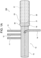
- An aorta treatment device 100 which is illustrated in Fig. 1 ( Fig. 1A and Fig. 1B ), includes: a branched artificial blood vessel portion 10 including four side tubes 11 to 14 that branch off from a main tube 15; a stent graft portion 20 coupled to a distal side of the branched artificial blood vessel portion 10 by being sutured to a distal end 16 of the branched artificial blood vessel portion 10; and a cuff portion 30 that is formed so as to extend from the distal end 16 of the branched artificial blood vessel portion 10 toward the distal side, that enters a state in which the cuff portion 30 extends from the distal end 16 of the branched artificial blood vessel portion 10 toward the proximal side by being everted, and that has an evertable skirt-like shape.
- the branched artificial blood vessel portion 10 of the treatment device 100 includes the main tube 15 and the four side tubes 11 to 14 that branch off from the main tube 15.
- the main tube 15 and the side tubes 11 to 14 are made from a tubular knit fabric.
- the main tube 15 and the side tubes 11 to 14 have ribs formed therein, are durable to extension/contraction and bending, resistant to kinking, and easily conformable to the shape of a blood vessel of a human body.
- the length (free length) of the main tube 15 is preferably 100 to 400 mm, and a preferable example is 210 mm.
- the inside diameter of the main tube 15 is preferably 16 to 36 mm, and a preferable example is 26 mm.
- the three side tube 11 to 13 form one group, and the side tube 14 is disposed so as to be displaced from this group.
- the length of the side tubes 11 to 14 is preferably 50 to 300 mm, and a preferable example is 210 mm.
- the inside diameter of the side tube 11 is preferably 5 to 14 mm, and a preferable example is 11 mm.
- the inside diameter of the side tubes 12 and 13 is preferably 5 to 12 mm, and a preferable example of each is 9 mm.
- the inside diameter of the side tube 14 is preferably 8 to 12 mm, and a preferable example is 9 mm.
- a tubular knit fabric from which the branched artificial blood vessel portion 10 (the main tube 15 and the side tubes 11 to 14) is made a tubular item made of a fabric or a knit of thermoplastic resin fiber may be used, and a plain weave fabric of thermoplastic resin fiber may be preferably used.
- the wall thickness of the tubular knit fabric is preferably 1 mm or smaller, and more preferably 0.3 to 0.7 mm.
- polyolefin such as polyethylene, polypropylene, or an ethylene- ⁇ -olefin copolymer
- polyamide polyurethane
- polyester such as polyethylene terephthalate, polybutylene terephthalate, polycyclohexane terephthalate, or polyethylene-2,6-naphtharate
- fluorocarbon resin such as PTFE or ETFE
- polyester such as polyethylene terephthalate and a fluorocarbon resin such as PTFE or ETFE, each of which is chemically stable, highly durable, and unlikely to cause a tissue reaction, are preferable; and polyester having a weight-average molecular weight of 10000 to 200000, in particular, a weight-average molecular weight of 15000 to 100000 is particularly preferable.
- the branched artificial blood vessel portion 10 is treated with a coating of collagen, gelatin, or the like, and thus leakage of blood from the branched artificial blood vessel portion 10 can be prevented.
- the stent graft portion 20 of the treatment device 100 includes a selfexpandable stent 21 that can be held in a reduced-diameter state and a graft 23 that covers an outer periphery of the stent 21.
- stent graft portion 20 is illustrated in an increased-diameter state in Fig. 1 ( Fig. 1A and Fig. 1B ), until the diameter is increased in a living blood vessel, the stent graft portion 20 is attached to a delivery shaft (not shown) in a reduced-diameter state.
- the length of the stent graft portion 20 is preferably 60 to 210 mm, and a preferable example is 110 mm.
- the diameter of the stent graft portion 20 in an increased-diameter state is larger than the diameter of the main tube 15 of the branched artificial blood vessel portion 10.
- the inside diameter of the stent graft portion 20 is preferably 16 to 39 mm, and a preferable example is 30 mm.
- the ratio of the inside diameter of the stent graft portion 20 to the inside diameter of the main tube 15 of the branched artificial blood vessel portion 10 is preferably 1.01 to 1.5, and a preferable example is 1.15 (30 mm/26 mm).
- the stent graft portion 20 When the inside diameter of the stent graft portion 20 is 1.01 times the inside diameter of the main tube 15 or larger, the stent graft portion 20 can be brought into sufficiently close contact with an inner wall of the distal aorta, with which close contact of a stent graft portion has been insufficient with an existing treatment device.
- the structure of the stent 21 of the stent graft portion 20 is not particularly limited, and examples of the structure include: a tubular structure made of a zig-zag wire material; a knit, fabric, or braid of one or a plurality of wire materials; a tubular structure in which a plurality of these are combined; a tubular structure formed by, for example, laser processing a plate-shaped or tubular structure made of a metal; and the like.
- a metal wire material of stainless steel, tantalum, titanium, platina, gold, tungsten, a shape memory alloy of Ni-Ti, Cu-Al-Ni, Cu-Zn-Al, or the like may be used; and the surface thereof may be covered with, for example, gold, platinum, or the like by means of plating or the like.
- the diameter of a wire material of the stent 21 is not particularly limited, and is preferably 0.08 to 1 mm.
- the thickness of a tubular metal structure of the stent 21 is not particularly limited, and is preferably 0.08 to 1 mm.
- thermoplastic resin to have a cylindrical shape by performing a forming method such as extrusion or blow molding, a knit fabric of thermoplastic resin fiber having a cylindrical shape, a non-woven fabric of a thermoplastic resin having a cylindrical shape, a thermoplastic resin sheet or a porous sheet having a cylindrical shape, or the like may be used.
- Ribs are not formed in the graft 23, and thus the graft 23 can be brought into sufficiently close contact with a blood vessel inner wall.
- thermoplastic resin material of the graft 23 examples include thermoplastic resins that have been shown above as examples of the material of thermoplastic resin fiber of the branched artificial blood vessel portion 10 (tubular knit fabric).
- the stent graft portion 20 (the graft 23) is not treated with the coating of an antithrombogenic material, with which the branched artificial blood vessel portion 10 is treated.
- the stent graft portion 20, which is not treated with a coating, is flexible and thus can be easily reduced in diameter, can properly fit to a blood vessel, and has high compatibility with a living tissue. Moreover, there is no negative effect on a diameter-increasing operation after being stored in a reduced-diameter state for a long period.
- the cuff portion 30 of the treatment device 100 is formed from a material (knit fabric) that is the same as the material of the branched artificial blood vessel portion 10 so as to be continuous with the distal end 16 of the branched artificial blood vessel portion 10.
- the branched artificial blood vessel portion 10 and the cuff portion 30 are formed from one tubular knit fabric. Moreover, the stent graft portion 20 is coupled to the branched artificial blood vessel portion 10 by being sutured to the distal end 16 of the branched artificial blood vessel portion 10.
- the treatment device 100 has high integrity between the branched artificial blood vessel portion 10 and the cuff portion 30, and can reliably avoid leakage of blood from a space between the branched artificial blood vessel portion 10 and the cuff portion 30.
- the cuff portion 30 of the treatment device 100 extends from the distal end 16 of the branched artificial blood vessel portion 10 toward the distal side so as to cover an outer periphery of a proximal end part of the stent graft portion 20, and an open end 31 of the cuff portion 30 is positioned on the distal side of the distal end 16 of the branched artificial blood vessel portion 10.
- the cuff portion 30 has a skirt-like shape such that the inside diameter of the open end 31 is larger than the inside diameter of the base end thereof (the distal end 16 of the branched artificial blood vessel portion 10).
- the length of the cuff portion 30 (the increased-diameter part of the tubular knit fabric) is preferably 5 to 30 mm, and a preferable example is 15 mm.
- the inside diameter of the cuff portion 30 at the base end is the same as the inside diameter of the main tube 15 of the branched artificial blood vessel portion 10.
- the inside diameter of the cuff portion 30 at the open end 31 is preferably 16 to 47 mm, and a preferable example is 28 mm.
- the ratio of the inside diameter of the open end 31 to the inside diameter of the base end of the cuff portion 30 is preferably 1.05 to 1.3, and a preferable example is 1.08 (28 mm/26 mm).
- suturing can be easily performed even if the shape (size) of the proximal end of the distal aorta has enlarged. Moreover, an operation of everting the cuff portion can also be easily performed.
- the cuff portion 30 can be everted so as to be turned inside out (so that an inner periphery and an outer periphery are reversed).
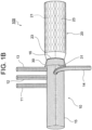
- Fig. 1B illustrates a state in which the cuff portion 30 is everted, the everted cuff portion 30 extends from the distal end 16 of the branched artificial blood vessel portion 10 toward the proximal side, and the open end 31 of the cuff portion 30 is positioned on the proximal side of the distal end 16 of the branched artificial blood vessel portion 10.
- the cuff portion 30 is treated with a coating of collagen, gelatin, or the like, and thus leakage of blood from the cuff portion 30 can be prevented.
- the treatment device 100 according to the present embodiment is attached by using a delivery system (not shown) as follows.
- the stent graft portion 20 in a reduced-diameter state is inserted from a disjoined part of an aortic arch into a distal aorta (descending part of aorta), and the position of the open end 31 of the everted cuff portion 30 is adjusted to substantially coincide with the position of the proximal end of the distal aorta.
- the stent graft portion 20 is increased in diameter and placed in the distal aorta.
- a distal aorta 90 and the branched artificial blood vessel portion 10 are anastomosed by suturing the proximal end part of the distal 0aorta 90 and the cuff portion 30 by using a suture thread 40.
- proximal end part of the distal aorta 90 and the cuff portion 30 can be disposed in substantially coaxial cylindrical shapes when suturing these, it is not necessary to perform a cumbersome operation, such as adjustment of the size of a collar, which has been performed when using an existing treatment device, these can be easily sutured, and tension does not remain after suturing.
- the branched artificial blood vessel portion 10 and the proximal aorta are anastomosed.
- Fig. 4 In the present embodiment illustrated in Fig. 4 ( Fig. 4A and Fig. 4B ), components that are the same as those of the first embodiment will be denoted the same numerals as in Fig. 1 ( Fig. 1A and Fig. 1B ), and the description thereof will be omitted.
- An aorta treatment device 200 which is illustrated in Fig. 4 ( Fig. 4A and Fig. 4B ), includes: a branched artificial blood vessel portion 10 including four side tubes 11 to 14 that branch off from a main tube 15; a stent graft portion 25 coupled to a distal side of the branched artificial blood vessel portion 10 by being sutured to a distal end 16 of the branched artificial blood vessel portion 10; and an evertable cuff portion 35 that is formed so as to extend from the distal end 16 of the branched artificial blood vessel portion 10 toward the distal side (see Fig. 4A ), and that enters a state in which the cuff portion 35 extends from the distal end 16 of the branched artificial blood vessel portion 10 toward the proximal side by being everted (see Fig. 4B ).
- the stent graft portion 25 of the treatment device 200 includes a selfexpandable stent 26 that can be held in a reduced-diameter state and a graft 28 that covers an outer periphery of the stent 26.
- stent graft portion 25 is illustrated in an increased-diameter state in Fig. 4 ( Fig. 4A and Fig. 4B ), until the diameter is increased in a living blood vessel, the stent graft portion 25 is attached to a delivery shaft (not shown) in a reduced-diameter state.
- the length of the stent graft portion 25 is the same as that of the stent graft portion 20 according to the first embodiment.
- the diameter of the stent graft portion 25 is substantially the same as the diameter of the main tube 15 of the branched artificial blood vessel portion 10 (the ratio of the inside diameter of the stent graft portion 25 to the inside diameter of the main tube 15 is 1.0).
- the structure, the material, and the like of the stent 26 and the graft 28 of the stent graft portion 25 are similar to those of the stent 21 and the graft 23 of the stent graft portion 20 according to the first embodiment.
- the cuff portion 35 of the treatment device 200 is formed from a material (knit fabric) that is the same as the material of the branched artificial blood vessel portion 10 so as to be continuous with the distal end 16 of the branched artificial blood vessel portion 10.
- the branched artificial blood vessel portion 10 and the cuff portion 35 are formed from one tubular knit fabric. Moreover, the stent graft portion 25 is coupled to the branched artificial blood vessel portion 10 by being sutured to the distal end 16 of the branched artificial blood vessel portion 10.
- the treatment device 100 has high integrity between the branched artificial blood vessel portion 10 and the cuff portion 35, and can reliably avoid leakage of blood from a space between the branched artificial blood vessel portion 10 and the cuff portion 35.
- the cuff portion 35 of the treatment device 200 extends from the distal end 16 of the branched artificial blood vessel portion 10 toward the distal side so as to cover an outer periphery of a proximal end part of the stent graft portion 25, and an open end 36 of the cuff portion 35 is positioned on the distal side of the distal end 16 of the branched artificial blood vessel portion 10.
- the cuff portion 35 has a substantially cylindrical shape such that the inside diameter of the base end thereof (the distal end 16 of the branched artificial blood vessel portion 10) is substantially equal to the inside diameter of the open end 36 (the inside diameter of the open end 36 is slightly larger).
- the length of the cuff portion 35 is 5 tc 30 mm, and a preferable example is 15 mm.
- the ratio of the inside diameter of the open end 36 to the inside diameter of the base end is lower than 1.5, and a preferable example is 1.02.
- the cuff portion 35 can be everted so as to be turned inside out (so that an inner periphery and an outer periphery are reversed).
- Fig. 4B illustrates a state in which the cuff portion 35 is everted, and the cuff portion 35 extends from the distal end 16 of the branched artificial blood vessel portion 10 toward the proximal side, and the open end 36 of the cuff portion 35 is positioned on the proximal side of the distal end 16 of the branched artificial blood vessel portion 10.
- the cuff portion 35 is treated with a coating of collagen, gelatin, or the like, and thus leakage of blood from the cuff portion 35 can be prevented.
- the treatment device 200 according to the present embodiment can be attached by using a delivery system (not shown) in a way similar to that of the treatment device 100 according to the first embodiment.
- the proximal end part of the distal aorta and the cuff portion 35 can be disposed in substantially coaxial cylindrical shapes when suturing these, it is not necessary to perform a cumbersome operation, such as adjustment of the size of a collar, which has been performed when using an existing treatment device, these can be easily sutured, and tension does not remain after suturing.
- treatment devices according to the disclosure may be modified in various ways.
- the number of side tubes that branch off from the main tube of the branched artificial blood vessel portion need not be four, and may be one, two, or three.
- the disposition of branches may be changed as appropriate.
- ribs may be formed in the graft of the stent graft portion, the forming density of the ribs may be lower than that of the branched artificial blood vessel portion.
- the branched artificial blood vessel portion and the cuff portion need not be formed from one tubular knit fabric, and, for example, the cuff portion may be sutured to the distal end of the tubular knit fabric of the branched artificial blood vessel portion. Ribs may be formed in the cuff portion.
- the ratio of the inside diameter of the stent graft portion to the inside diameter of the main tube of the branched artificial blood vessel portion may be lower than 1.0 (for example, 0.8 or higher and lower than 1.0).
Landscapes
- Health & Medical Sciences (AREA)
- Engineering & Computer Science (AREA)
- Biomedical Technology (AREA)
- Heart & Thoracic Surgery (AREA)
- Oral & Maxillofacial Surgery (AREA)
- Transplantation (AREA)
- Cardiology (AREA)
- Vascular Medicine (AREA)
- Life Sciences & Earth Sciences (AREA)
- Animal Behavior & Ethology (AREA)
- General Health & Medical Sciences (AREA)
- Public Health (AREA)
- Veterinary Medicine (AREA)
- Pulmonology (AREA)
- Gastroenterology & Hepatology (AREA)
- Prostheses (AREA)
Description
- The present invention relates to a treatment device for treating a disease in a thoracic aorta.
- As a method for treating a disease in a thoracic aorta, such as an aortic aneurysm or an aortic dissection, artificial blood vessel replacement surgery and stent graft insertion are performed.
- Here, as an artificial blood vessel used for artificial blood vessel replacement surgery of replacing an aortic arch, a branched artificial blood vessel including four side-branch tubes is known (see PTL 1). As a stent graft used for stent graft insertion, various types are known, and, for example, a stent graft having a structure that can improve utility for a treatment using an OSG (Open Stent Graft) method has been proposed by the present applicant (see PTL 2).
- Recently, in order to improve the efficiency of manipulation, an aorta treatment device having a structure in which a branched artificial blood vessel, including four side-branch tubes, and a stent graft are sutured and integrated has been introduced.
-
Fig. 5 is a view illustrating such a treatment device, and thetreatment device 1 includes a branched artificialblood vessel portion 3, astent graft portion 5 sutured to the distal side thereof, and a flange-shaped collar 7 attached to the sutured part of the branched artificialblood vessel portion 3 and thestent graft portion 5. - The
treatment device 1 is attached by using a delivery system (not shown) as follows. First, from a disjoined part after an aortic arch has been excised, thestent graft portion 5 in a reduced-diameter state is inserted into a distal aorta (descending part of aorta), which is a living blood vessel, and thetreatment device 1 is disposed so as to block an opening in a proximal end part (the disjoined part) of the distal aorta with the flange-shaped collar 7. - Next, the
stent graft portion 5 is increased in diameter and thus brought into close contact with an inner wall of the distal aorta, the size of thecollar 7 is adjusted by cutting off a part thereof as necessary, and the distal aorta and the branched artificialblood vessel portion 3 are anastomosed by suturing thecollar 7, which has been cut to an appropriate size, and the proximal end part of the distal aorta. Subsequently, by suturing a proximal end part of the branched artificialblood vessel portion 3 and a proximal aorta (ascending part of aorta), which is a living blood vessel, the branched artificialblood vessel portion 3 and the proximal aorta are anastomosed. Further relevant prior art is described inWO 2018/032358 A1 ,EP 3 578 134 A2US 2011/270378 A1 . HereinEP 3 578 134 A2 -
- PTL 1:
Japanese Unexamined Patent Application Publication No. 7-308330 - PTL 2:
Japanese Unexamined Patent Application Publication No. 2017-23464 - However, the treatment device described above has a problem in that it is extremely difficult to perform the manipulation of aligning the position of the proximal end part of the distal aorta, whose end surface shape differs among patients, with the position of the flange-shaped collar, and suturing these while adjusting the shapes and the sizes thereof; and tension tends to remain after suturing.
- Moreover, the inside diameter of the distal aorta, which includes a lesion such as an aortic aneurysm or an aorta dissection, has individual difference among patients, and there is a case where it is not possible to bring the stent graft portion into sufficiently close contact with the inner wall of the distal aorta by using the treatment device described above.
- The present invention has been made based on the circumstances described above.
- An object of the present invention is to provide an aorta treatment device that can replace an aortic arch with a branched artificial blood vessel portion, place a stent graft portion in a distal aorta, and anastomose the branched artificial blood vessel portion with the distal aorta easily compared with an existing device.
- Another object of the present invention is to provide an aorta treatment device including a stent graft portion that can be brought into sufficiently close contact with an inner wall of a distal aorta, with which close contact of a stent graft portion of an existing treatment device is insufficient.
- In particular it is provided an aorta treatment device, having the feature defined in
claim 1. Further preferred embodiments are defined in the dependent claims. - (1) An aorta treatment device according to the present invention includes: a branched artificial blood vessel portion including a main tube and at least one side tube that branches off from the main tube; a stent graft portion coupled to a distal side of the branched artificial blood vessel portion; and a cuff portion that is formed so as to extend from a distal end of the branched artificial blood vessel portion toward the distal side, that is evertable so as to enter a state in which the cuff portion extends from the distal end of the branched artificial blood vessel portion toward a proximal side, and that has a cylindrical shape or a skirt-like shape.
- With the treatment device having such a configuration, it is possible to anastomose a distal aorta and the branched artificial blood vessel portion by: everting the cuff portion; inserting the stent graft portion in a reduced-diameter state into the distal aorta until the position of an open end of the everted cuff portion substantially coincides with the position of a proximal end of the distal aorta; increasing the stent graft portion in diameter and placing the stent graft portion in the distal aorta; and then suturing the proximal end part of the distal aorta and the everted cuff portion.
- Here, because the proximal end part of the distal aorta and the cuff portion can be disposed in substantially coaxial cylindrical shapes when suturing these, it is significantly easy to perform manipulation of suturing these, compared with an existing treatment device including a flange-shaped collar, and tension does not remain after suturing.
- (2) In the aorta treatment device according to the present invention, preferably, the branched artificial blood vessel portion includes four side tubes that branch off from the main tube.
- (3) In the aorta treatment device according to the present invention, preferably, the cuff portion is formed from a material that is the same as a material of the branched artificial blood vessel portion so as to be continuous with the distal end of the branched artificial blood vessel portion (that is, the branched artificial blood vessel portion and the cuff portion are formed from a common tubular knit fabric), and the stent graft portion is coupled to the branched artificial blood vessel portion by being sutured to the distal end of the branched artificial blood vessel portion.
- With the treatment device having such a configuration, the integrity of the branched artificial blood vessel portion with the cuff portion can be further improved.
- (4) In the aorta treatment device according to the present invention, preferably, a ratio of an inside diameter of the stent graft portion to an inside diameter of the main tube of the branched artificial blood vessel portion is 1.01 to 1.5.
- With the treatment device having such a configuration, because the inside diameter ratio is 1.01 or higher, the stent graft portion can be brought into sufficiently close contact with an inner wall of the distal aorta, with which close contact of a stent graft portion has been insufficient with an existing treatment device.
- (5) In the aorta treatment device according to the present invention, the cuff portion has a skirt-like shape such that a length thereof is 5 to 30 mm and a ratio of an inside diameter of an open end to an inside diameter of a base end is 1.05 to 1.3.
- With the treatment device having such a configuration, due to the skirt-like shape such that the inside diameter ratio is 1.3 or lower, suturing with the proximal end part of the distal aorta can be more easily performed.
- Moreover, because the inside diameter ratio is 1.05 or higher, suturing can be easily performed even if the shape (size) of the proximal end of the distal aorta has enlarged. Furthermore, an operation of everting the cuff portion is also easy.
- (6) In the aorta treatment device according to the present invention, preferably, the branched artificial blood vessel portion and the cuff portion are treated with a coating for preventing leakage of blood, and the stent graft portion is not treated with the coating.
- With the treatment device having such a configuration, leakage of blood from the branched artificial blood vessel portion and the cuff portion, which are treated with the coating, can be prevented; and the stent graft portion, which is not treated with the coating, is flexible and thus can be easily reduced in diameter, can properly fit with a blood vessel, and has high compatibility with a living tissue. Moreover, there is no negative effect on a diameter-increasing operation after being stored in a reduced-diameter state for a long period, and storage stability is high.
- With the treatment device according to the present invention, it is possible to replace an aortic arch with a branched artificial blood vessel portion, place a stent graft portion in a distal aorta, and anastomose the branched artificial blood vessel portion and the distal aorta easily compared with an existing treatment device.
- With the treatment device according to the present invention including the stent graft portion having an inside diameter that is 1.01 times the inside diameter of the main tube of the branched artificial blood vessel portion or larger, the stent graft portion of the treatment device according to the present invention can be brought into sufficiently close contact with an inner wall of the distal aorta, with which a stent graft portion of an existing treatment device has not been capable of being brought into sufficiently close contact.
-
- [
Fig. 1A] Fig. 1A is a view of an aorta treatment device according to an embodiment of the present invention, illustrating a state in which a cuff portion is not everted. - [
Fig. 1B] Fig. 1B is a view of the aorta treatment device according to the embodiment of the present invention, illustrating a state in which the cuff portion is everted. - [
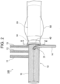
Fig. 2] Fig. 2 is a view illustrating a state in which the aorta treatment device shown inFig. 1 is in use. - [
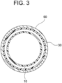
Fig. 3] Fig. 3 is a sectional view taken along line III-III ofFig. 2 . - [
Fig. 4A] Fig. 4A is a view of an aorta treatment device according to another embodiment of the present invention, illustrating a state in which a cuff portion is not everted. - [
Fig. 4B] Fig. 4B is a view of the aorta treatment device according to the other embodiment of the present invention, illustrating a state in which the cuff portion is everted. - [
Fig. 5] Fig. 5 is a perspective view of an existing aorta treatment device. - Hereinafter, an aorta treatment device according to an embodiment of the present invention will be described in detail.
- An
aorta treatment device 100 according to the present embodiment, which is illustrated inFig. 1 (Fig. 1A andFig. 1B ), includes: a branched artificialblood vessel portion 10 including fourside tubes 11 to 14 that branch off from amain tube 15; astent graft portion 20 coupled to a distal side of the branched artificialblood vessel portion 10 by being sutured to adistal end 16 of the branched artificialblood vessel portion 10; and acuff portion 30 that is formed so as to extend from thedistal end 16 of the branched artificialblood vessel portion 10 toward the distal side, that enters a state in which thecuff portion 30 extends from thedistal end 16 of the branched artificialblood vessel portion 10 toward the proximal side by being everted, and that has an evertable skirt-like shape. - The branched artificial
blood vessel portion 10 of thetreatment device 100 according to the present embodiment includes themain tube 15 and the fourside tubes 11 to 14 that branch off from themain tube 15. - The
main tube 15 and theside tubes 11 to 14 are made from a tubular knit fabric. - The
main tube 15 and theside tubes 11 to 14 have ribs formed therein, are durable to extension/contraction and bending, resistant to kinking, and easily conformable to the shape of a blood vessel of a human body. - The length (free length) of the
main tube 15 is preferably 100 to 400 mm, and a preferable example is 210 mm. - The inside diameter of the
main tube 15 is preferably 16 to 36 mm, and a preferable example is 26 mm. - Among the
side tubes 11 to 14 that branch off from themain tube 15, the threeside tube 11 to 13 form one group, and theside tube 14 is disposed so as to be displaced from this group. - The length of the
side tubes 11 to 14 is preferably 50 to 300 mm, and a preferable example is 210 mm. - The inside diameter of the
side tube 11 is preferably 5 to 14 mm, and a preferable example is 11 mm. - The inside diameter of the
side tubes - The inside diameter of the
side tube 14 is preferably 8 to 12 mm, and a preferable example is 9 mm. - As a tubular knit fabric from which the branched artificial blood vessel portion 10 (the
main tube 15 and theside tubes 11 to 14) is made, a tubular item made of a fabric or a knit of thermoplastic resin fiber may be used, and a plain weave fabric of thermoplastic resin fiber may be preferably used. - The wall thickness of the tubular knit fabric is preferably 1 mm or smaller, and more preferably 0.3 to 0.7 mm.
- Examples of a thermoplastic resin that forms the thermoplastic resin fiber include: polyolefin such as polyethylene, polypropylene, or an ethylene-α-olefin copolymer; polyamide; polyurethane; polyester such as polyethylene terephthalate, polybutylene terephthalate, polycyclohexane terephthalate, or polyethylene-2,6-naphtharate; a fluorocarbon resin such as PTFE or ETFE; and the like. Among these, polyester such as polyethylene terephthalate and a fluorocarbon resin such as PTFE or ETFE, each of which is chemically stable, highly durable, and unlikely to cause a tissue reaction, are preferable; and polyester having a weight-average molecular weight of 10000 to 200000, in particular, a weight-average molecular weight of 15000 to 100000 is particularly preferable.
- The branched artificial
blood vessel portion 10 is treated with a coating of collagen, gelatin, or the like, and thus leakage of blood from the branched artificialblood vessel portion 10 can be prevented. - The
stent graft portion 20 of thetreatment device 100 according to the present embodiment includes aselfexpandable stent 21 that can be held in a reduced-diameter state and agraft 23 that covers an outer periphery of thestent 21. - Although the
stent graft portion 20 is illustrated in an increased-diameter state inFig. 1 (Fig. 1A andFig. 1B ), until the diameter is increased in a living blood vessel, thestent graft portion 20 is attached to a delivery shaft (not shown) in a reduced-diameter state. - The length of the
stent graft portion 20 is preferably 60 to 210 mm, and a preferable example is 110 mm. - As illustrated in
Fig. 1 (Fig. 1A andFig. 1B ), the diameter of thestent graft portion 20 in an increased-diameter state is larger than the diameter of themain tube 15 of the branched artificialblood vessel portion 10. - Here, the inside diameter of the
stent graft portion 20 is preferably 16 to 39 mm, and a preferable example is 30 mm. - The ratio of the inside diameter of the
stent graft portion 20 to the inside diameter of themain tube 15 of the branched artificialblood vessel portion 10 is preferably 1.01 to 1.5, and a preferable example is 1.15 (30 mm/26 mm). - When the inside diameter of the
stent graft portion 20 is 1.01 times the inside diameter of themain tube 15 or larger, thestent graft portion 20 can be brought into sufficiently close contact with an inner wall of the distal aorta, with which close contact of a stent graft portion has been insufficient with an existing treatment device. - The structure of the
stent 21 of thestent graft portion 20 is not particularly limited, and examples of the structure include: a tubular structure made of a zig-zag wire material; a knit, fabric, or braid of one or a plurality of wire materials; a tubular structure in which a plurality of these are combined; a tubular structure formed by, for example, laser processing a plate-shaped or tubular structure made of a metal; and the like. - As a wire material and the material of a tubular metal structure of the
stent 21, a metal wire material of stainless steel, tantalum, titanium, platina, gold, tungsten, a shape memory alloy of Ni-Ti, Cu-Al-Ni, Cu-Zn-Al, or the like may be used; and the surface thereof may be covered with, for example, gold, platinum, or the like by means of plating or the like. - The diameter of a wire material of the
stent 21 is not particularly limited, and is preferably 0.08 to 1 mm. - The thickness of a tubular metal structure of the
stent 21 is not particularly limited, and is preferably 0.08 to 1 mm. - As the
graft 23 of thestent graft portion 20, an item formed from a thermoplastic resin to have a cylindrical shape by performing a forming method such as extrusion or blow molding, a knit fabric of thermoplastic resin fiber having a cylindrical shape, a non-woven fabric of a thermoplastic resin having a cylindrical shape, a thermoplastic resin sheet or a porous sheet having a cylindrical shape, or the like may be used. - Ribs are not formed in the
graft 23, and thus thegraft 23 can be brought into sufficiently close contact with a blood vessel inner wall. - Examples of a thermoplastic resin material of the
graft 23 include thermoplastic resins that have been shown above as examples of the material of thermoplastic resin fiber of the branched artificial blood vessel portion 10 (tubular knit fabric). - The stent graft portion 20 (the graft 23) is not treated with the coating of an antithrombogenic material, with which the branched artificial
blood vessel portion 10 is treated. - The
stent graft portion 20, which is not treated with a coating, is flexible and thus can be easily reduced in diameter, can properly fit to a blood vessel, and has high compatibility with a living tissue. Moreover, there is no negative effect on a diameter-increasing operation after being stored in a reduced-diameter state for a long period. - The
cuff portion 30 of thetreatment device 100 according to the present embodiment is formed from a material (knit fabric) that is the same as the material of the branched artificialblood vessel portion 10 so as to be continuous with thedistal end 16 of the branched artificialblood vessel portion 10. - That is, the branched artificial
blood vessel portion 10 and thecuff portion 30 are formed from one tubular knit fabric. Moreover, thestent graft portion 20 is coupled to the branched artificialblood vessel portion 10 by being sutured to thedistal end 16 of the branched artificialblood vessel portion 10. - Thus, the
treatment device 100 has high integrity between the branched artificialblood vessel portion 10 and thecuff portion 30, and can reliably avoid leakage of blood from a space between the branched artificialblood vessel portion 10 and thecuff portion 30. - As illustrated in
Fig. 1A , in a non-everted state, thecuff portion 30 of thetreatment device 100 extends from thedistal end 16 of the branched artificialblood vessel portion 10 toward the distal side so as to cover an outer periphery of a proximal end part of thestent graft portion 20, and anopen end 31 of thecuff portion 30 is positioned on the distal side of thedistal end 16 of the branched artificialblood vessel portion 10. - The
cuff portion 30 has a skirt-like shape such that the inside diameter of theopen end 31 is larger than the inside diameter of the base end thereof (thedistal end 16 of the branched artificial blood vessel portion 10). - Here, the length of the cuff portion 30 (the increased-diameter part of the tubular knit fabric) is preferably 5 to 30 mm, and a preferable example is 15 mm.
- The inside diameter of the
cuff portion 30 at the base end is the same as the inside diameter of themain tube 15 of the branched artificialblood vessel portion 10. - The inside diameter of the
cuff portion 30 at theopen end 31 is preferably 16 to 47 mm, and a preferable example is 28 mm. - The ratio of the inside diameter of the
open end 31 to the inside diameter of the base end of the cuff portion 30 (the inside diameter of themain tube 15 of the branched artificial blood vessel portion 10) is preferably 1.05 to 1.3, and a preferable example is 1.08 (28 mm/26 mm). - Because the inside diameter ratio is 1.05 or higher, suturing can be easily performed even if the shape (size) of the proximal end of the distal aorta has enlarged. Moreover, an operation of everting the cuff portion can also be easily performed.
- Although it is difficult to perform suturing with a proximal end part of the distal aorta if the inside diameter ratio is excessively high (the inside diameter of the
open end 31 >> the inside diameter of the base end), when the inside diameter ratio is 1.3 or lower, suturing with the proximal end part of the distal aorta can be easily performed. - The
cuff portion 30 can be everted so as to be turned inside out (so that an inner periphery and an outer periphery are reversed). -
Fig. 1B illustrates a state in which thecuff portion 30 is everted, the evertedcuff portion 30 extends from thedistal end 16 of the branched artificialblood vessel portion 10 toward the proximal side, and theopen end 31 of thecuff portion 30 is positioned on the proximal side of thedistal end 16 of the branched artificialblood vessel portion 10. - The
cuff portion 30 is treated with a coating of collagen, gelatin, or the like, and thus leakage of blood from thecuff portion 30 can be prevented. - The
treatment device 100 according to the present embodiment is attached by using a delivery system (not shown) as follows. - First, in a state in which the
cuff portion 30 is everted, thestent graft portion 20 in a reduced-diameter state is inserted from a disjoined part of an aortic arch into a distal aorta (descending part of aorta), and the position of theopen end 31 of the evertedcuff portion 30 is adjusted to substantially coincide with the position of the proximal end of the distal aorta. Next, thestent graft portion 20 is increased in diameter and placed in the distal aorta. - Subsequently, as illustrated in
Fig. 2 , adistal aorta 90 and the branched artificialblood vessel portion 10 are anastomosed by suturing the proximal end part of the distal 0aorta 90 and thecuff portion 30 by using asuture thread 40. - As illustrated in
Fig. 2 andFig. 3 , because the proximal end part of thedistal aorta 90 and thecuff portion 30 can be disposed in substantially coaxial cylindrical shapes when suturing these, it is not necessary to perform a cumbersome operation, such as adjustment of the size of a collar, which has been performed when using an existing treatment device, these can be easily sutured, and tension does not remain after suturing. - Subsequently, by suturing the proximal end part of the branched artificial
blood vessel portion 10 and the proximal aorta (ascending part of aorta), the branched artificialblood vessel portion 10 and the proximal aorta are anastomosed. - Next, an artificial blood vessel according to another embodiment of the present invention will be described in detail.
- In the present embodiment illustrated in
Fig. 4 (Fig. 4A andFig. 4B ), components that are the same as those of the first embodiment will be denoted the same numerals as inFig. 1 (Fig. 1A andFig. 1B ), and the description thereof will be omitted. - An
aorta treatment device 200 according to the present embodiment, which is illustrated inFig. 4 (Fig. 4A andFig. 4B ), includes: a branched artificialblood vessel portion 10 including fourside tubes 11 to 14 that branch off from amain tube 15; astent graft portion 25 coupled to a distal side of the branched artificialblood vessel portion 10 by being sutured to adistal end 16 of the branched artificialblood vessel portion 10; and anevertable cuff portion 35 that is formed so as to extend from thedistal end 16 of the branched artificialblood vessel portion 10 toward the distal side (seeFig. 4A ), and that enters a state in which thecuff portion 35 extends from thedistal end 16 of the branched artificialblood vessel portion 10 toward the proximal side by being everted (seeFig. 4B ). - The
stent graft portion 25 of thetreatment device 200 according to the present embodiment includes aselfexpandable stent 26 that can be held in a reduced-diameter state and agraft 28 that covers an outer periphery of thestent 26. - Although the
stent graft portion 25 is illustrated in an increased-diameter state inFig. 4 (Fig. 4A andFig. 4B ), until the diameter is increased in a living blood vessel, thestent graft portion 25 is attached to a delivery shaft (not shown) in a reduced-diameter state. - The length of the
stent graft portion 25 is the same as that of thestent graft portion 20 according to the first embodiment. - The diameter of the
stent graft portion 25 is substantially the same as the diameter of themain tube 15 of the branched artificial blood vessel portion 10 (the ratio of the inside diameter of thestent graft portion 25 to the inside diameter of themain tube 15 is 1.0). - The structure, the material, and the like of the
stent 26 and thegraft 28 of thestent graft portion 25 are similar to those of thestent 21 and thegraft 23 of thestent graft portion 20 according to the first embodiment. - The
cuff portion 35 of thetreatment device 200 according to the present embodiment is formed from a material (knit fabric) that is the same as the material of the branched artificialblood vessel portion 10 so as to be continuous with thedistal end 16 of the branched artificialblood vessel portion 10. - That is, the branched artificial
blood vessel portion 10 and thecuff portion 35 are formed from one tubular knit fabric. Moreover, thestent graft portion 25 is coupled to the branched artificialblood vessel portion 10 by being sutured to thedistal end 16 of the branched artificialblood vessel portion 10. - Thus, the
treatment device 100 has high integrity between the branched artificialblood vessel portion 10 and thecuff portion 35, and can reliably avoid leakage of blood from a space between the branched artificialblood vessel portion 10 and thecuff portion 35. - As illustrated in
Fig. 4A , in a non-everted state, thecuff portion 35 of thetreatment device 200 extends from thedistal end 16 of the branched artificialblood vessel portion 10 toward the distal side so as to cover an outer periphery of a proximal end part of thestent graft portion 25, and anopen end 36 of thecuff portion 35 is positioned on the distal side of thedistal end 16 of the branched artificialblood vessel portion 10. - The
cuff portion 35 has a substantially cylindrical shape such that the inside diameter of the base end thereof (thedistal end 16 of the branched artificial blood vessel portion 10) is substantially equal to the inside diameter of the open end 36 (the inside diameter of theopen end 36 is slightly larger). - The length of the
cuff portion 35 is 5tc 30 mm, and a preferable example is 15 mm. - The ratio of the inside diameter of the
open end 36 to the inside diameter of the base end is lower than 1.5, and a preferable example is 1.02. - The
cuff portion 35 can be everted so as to be turned inside out (so that an inner periphery and an outer periphery are reversed). -
Fig. 4B illustrates a state in which thecuff portion 35 is everted, and thecuff portion 35 extends from thedistal end 16 of the branched artificialblood vessel portion 10 toward the proximal side, and theopen end 36 of thecuff portion 35 is positioned on the proximal side of thedistal end 16 of the branched artificialblood vessel portion 10. - The
cuff portion 35 is treated with a coating of collagen, gelatin, or the like, and thus leakage of blood from thecuff portion 35 can be prevented. - The
treatment device 200 according to the present embodiment can be attached by using a delivery system (not shown) in a way similar to that of thetreatment device 100 according to the first embodiment. - With the
treatment device 200 according to the present embodiment, because the proximal end part of the distal aorta and thecuff portion 35 can be disposed in substantially coaxial cylindrical shapes when suturing these, it is not necessary to perform a cumbersome operation, such as adjustment of the size of a collar, which has been performed when using an existing treatment device, these can be easily sutured, and tension does not remain after suturing. - Heretofore, treatment devices according to the disclosure may be modified in various ways.
- For example, the number of side tubes that branch off from the main tube of the branched artificial blood vessel portion need not be four, and may be one, two, or three. Moreover, the disposition of branches may be changed as appropriate.
- Although ribs may be formed in the graft of the stent graft portion, the forming density of the ribs may be lower than that of the branched artificial blood vessel portion.
- The branched artificial blood vessel portion and the cuff portion need not be formed from one tubular knit fabric, and, for example, the cuff portion may be sutured to the distal end of the tubular knit fabric of the branched artificial blood vessel portion. Ribs may be formed in the cuff portion.
- The ratio of the inside diameter of the stent graft portion to the inside diameter of the main tube of the branched artificial blood vessel portion may be lower than 1.0 (for example, 0.8 or higher and lower than 1.0). Reference Signs List
-
- 100
- aorta treatment device
- 10
- branched artificial blood vessel portion
- 11 to 14
- side tubes
- 15
- main tube
- 16
- distal end of branched artificial blood vessel portion
- 20
- stent graft portion
- 21
- stent
- 23
- graft
- 30
- cuff portion
- 31
- open end of cuff portion
- 200
- aorta treatment device
- 25
- stent graft portion
- 26
- stent
- 28
- graft
- 35
- cuff portion
- 36
- open end of cuff portion
- 40
- suture thread
Claims (5)
- An aorta treatment device (100, 200) comprising:a branched artificial blood vessel portion (10) including a main tube (15) and at least one side tube (11, 12, 13, 14) that branches off from the main tube (15);a stent graft portion (20, 25) coupled to a distal side of the branched artificial blood vessel portion (10); anda cuff portion (30) that is formed so as to extend from a distal end of the branched artificial blood vessel portion (10) toward the distal side, that is evertable so as to extend from the distal end of the branched artificial blood vessel portion (10) toward a proximal side, and that has a cylindrical shape or a skirt-like shape, wherein the cuff portion (30) has a skirt-like shape such that a length thereof is 5 to 30 mm and a ratio of an inside diameter of an open end to an inside diameter of a base end is 1.05 to 1.3.
- The aorta treatment device (100, 200) according to Claim 1, wherein the branched artificial blood vessel portion (10) includes four side tubes (11, 12, 13, 14) that branch off from the main tube (15).
- The aorta treatment device (100, 200) according to Claim 1 or 2, wherein the cuff portion (30) is formed from a material that is the same as a material of the branched artificial blood vessel portion (10) so as to be continuous with the distal end of the branched artificial blood vessel portion (10), and wherein the stent graft portion (30) is coupled to the branched artificial blood vessel portion (10) by being sutured to the distal end of the branched artificial blood vessel portion (10).
- The aorta treatment device (100, 200) according to any one of Claims 1 to 3, wherein a ratio of an inside diameter of the stent graft portion (20, 25) to an inside diameter of the main tube (15) of the branched artificial blood vessel portion (10) is 1.01 to 1.5.
- The aorta treatment device (100, 200) according to any one of Claims 1 to 4, wherein the branched artificial blood vessel portion (10) and the cuff portion (30) are treated with a coating for preventing leakage of blood, and the stent graft portion (20, 25) is not treated with the coating.
Applications Claiming Priority (2)
| Application Number | Priority Date | Filing Date | Title |
|---|---|---|---|
| JP2018043445A JP6698262B2 (en) | 2018-03-09 | 2018-03-09 | Aortic treatment device |
| PCT/JP2018/045473 WO2019171694A1 (en) | 2018-03-09 | 2018-12-11 | Aorta treatment device |
Publications (3)
| Publication Number | Publication Date |
|---|---|
| EP3763327A1 EP3763327A1 (en) | 2021-01-13 |
| EP3763327A4 EP3763327A4 (en) | 2021-04-14 |
| EP3763327B1 true EP3763327B1 (en) | 2024-05-15 |
Family
ID=67845925
Family Applications (1)
| Application Number | Title | Priority Date | Filing Date |
|---|---|---|---|
| EP18909066.5A Active EP3763327B1 (en) | 2018-03-09 | 2018-12-11 | Aorta treatment device |
Country Status (5)
| Country | Link |
|---|---|
| EP (1) | EP3763327B1 (en) |
| JP (1) | JP6698262B2 (en) |
| KR (1) | KR102394785B1 (en) |
| TW (1) | TWI700079B (en) |
| WO (1) | WO2019171694A1 (en) |
Families Citing this family (3)
| Publication number | Priority date | Publication date | Assignee | Title |
|---|---|---|---|---|
| CN110897761A (en) * | 2019-12-29 | 2020-03-24 | 黄健兵 | Novel isolated aortic arch portion and three-branch tectorial membrane support type blood vessel combination external member |
| CN112190363A (en) * | 2020-10-16 | 2021-01-08 | 江苏百优达生命科技有限公司 | Integrated intravascular stent and conveying system |
| CN114767328A (en) * | 2022-06-22 | 2022-07-22 | 上海微创心脉医疗科技(集团)股份有限公司 | Medical system and auxiliary device |
Family Cites Families (17)
| Publication number | Priority date | Publication date | Assignee | Title |
|---|---|---|---|---|
| JP2798173B2 (en) | 1994-05-17 | 1998-09-17 | 宇部興産株式会社 | Bifurcated vascular graft |
| US7226474B2 (en) * | 2000-05-01 | 2007-06-05 | Endovascular Technologies, Inc. | Modular graft component junctions |
| EP1245202B1 (en) * | 2001-03-27 | 2004-08-04 | William Cook Europe ApS | An aortic graft device |
| US7044962B2 (en) * | 2002-06-25 | 2006-05-16 | Scimed Life Systems, Inc. | Implantable prosthesis with displaceable skirt |
| WO2004006807A2 (en) * | 2002-07-11 | 2004-01-22 | University Of Virginia Patent Foundation | Methods and apparatuses for repairing aneurysms |
| AU2003272226A1 (en) * | 2002-08-20 | 2004-03-11 | Cook Incorporated | Stent graft with improved proximal end |
| US20040225349A1 (en) * | 2003-05-09 | 2004-11-11 | Thistle Robert C. | Eversible locking mechanism for modular stents |
| CN2817768Y (en) * | 2005-05-24 | 2006-09-20 | 微创医疗器械(上海)有限公司 | Tectorium stand and host cage section thereof |
| WO2010124095A1 (en) | 2009-04-23 | 2010-10-28 | Samuels Shaun L W | Endovascular router device and method |
| WO2010150208A2 (en) * | 2009-06-23 | 2010-12-29 | Endospan Ltd. | Vascular prostheses for treating aneurysms |
| US8333800B2 (en) * | 2010-04-29 | 2012-12-18 | Medtronic Vascular, Inc. | Mobile external coupling with internal sealing cuff for branch vessel connection |
| JP5801119B2 (en) * | 2010-09-21 | 2015-10-28 | テルモ株式会社 | Artificial blood vessel system |
| WO2014059114A2 (en) | 2012-10-10 | 2014-04-17 | Trivascular, Inc. | Endovascular graft for aneurysms involving major branch vessels |
| JP6200465B2 (en) | 2015-07-23 | 2017-09-20 | 日本ライフライン株式会社 | Stent graft |
| WO2018032358A1 (en) * | 2016-08-16 | 2018-02-22 | Dalian Corvivo Medical, Co. Ltd | Endoprosthesis having graft portion and stent graft portion |
| GB2556116B (en) | 2016-11-22 | 2019-12-11 | Cook Medical Technologies Llc | Graft for treating the distal aortic arch and descending aorta in type a patients |
| US10905541B2 (en) * | 2018-06-04 | 2021-02-02 | Cook Medical Technologies Llc | Branched frozen elephant trunk device and method |
-
2018
- 2018-03-09 JP JP2018043445A patent/JP6698262B2/en active Active
- 2018-12-11 KR KR1020207025442A patent/KR102394785B1/en active IP Right Grant
- 2018-12-11 EP EP18909066.5A patent/EP3763327B1/en active Active
- 2018-12-11 WO PCT/JP2018/045473 patent/WO2019171694A1/en active Application Filing
-
2019
- 2019-02-01 TW TW108104023A patent/TWI700079B/en not_active IP Right Cessation
Also Published As
| Publication number | Publication date |
|---|---|
| JP2019154666A (en) | 2019-09-19 |
| JP6698262B2 (en) | 2020-05-27 |
| KR102394785B1 (en) | 2022-05-09 |
| TWI700079B (en) | 2020-08-01 |
| WO2019171694A1 (en) | 2019-09-12 |
| EP3763327A4 (en) | 2021-04-14 |
| TW201938118A (en) | 2019-10-01 |
| EP3763327A1 (en) | 2021-01-13 |
| KR20200118127A (en) | 2020-10-14 |
Similar Documents
| Publication | Publication Date | Title |
|---|---|---|
| US11607304B2 (en) | Endoluminal prosthesis having multiple branches or fenestrations and methods of deployment | |
| EP1965732B1 (en) | Endoluminal device including a mechanism for proximal or distal fixation, and sealing and methods of use thereof | |
| CN109152639B (en) | Stent grafts and methods of use for treating aneurysms | |
| US20190192320A1 (en) | Prosthesis having an everting pivoting fenestration | |
| US9198787B2 (en) | Conformable prosthesis delivery system and method for deployment thereof | |
| EP1737389B1 (en) | Stent graft repair device | |
| US9265599B2 (en) | Retention system for an endoluminal device | |
| US20160184078A1 (en) | Sectional Inserts for Trunk Section in Endoprosthesis for Aortic Aneurysm | |
| EP3763327B1 (en) | Aorta treatment device | |
| WO2016109763A1 (en) | Circular sectional inserts for insertion with a trunk section in endoprosthesis for aortic aneurysm | |
| US20040106974A1 (en) | Thoracic introducer | |
| CN103860292A (en) | Preloaded wire for endoluminal device | |
| US20160184077A1 (en) | Circular Sectional Inserts For Insertion with a Trunk Section in Endoprosthesis for Aortic Aneurysm | |
| EP3578134B1 (en) | Branched frozen elephant trunk device | |
| US20070219622A1 (en) | Stent-graft structure having one or more stent pockets | |
| US20160184076A1 (en) | Implantable Endoprosthesis for Aortic Aneurysm | |
| US20140277371A1 (en) | Atraumatic stent crowns | |
| JP7446407B2 (en) | Delivery shaft and delivery system | |
| WO2021176673A1 (en) | Delivery shaft and delivery system |
Legal Events
| Date | Code | Title | Description |
|---|---|---|---|
| STAA | Information on the status of an ep patent application or granted ep patent |
Free format text: STATUS: THE INTERNATIONAL PUBLICATION HAS BEEN MADE |
|
| PUAI | Public reference made under article 153(3) epc to a published international application that has entered the european phase |
Free format text: ORIGINAL CODE: 0009012 |
|
| STAA | Information on the status of an ep patent application or granted ep patent |
Free format text: STATUS: REQUEST FOR EXAMINATION WAS MADE |
|
| 17P | Request for examination filed |
Effective date: 20200811 |
|
| AK | Designated contracting states |
Kind code of ref document: A1 Designated state(s): AL AT BE BG CH CY CZ DE DK EE ES FI FR GB GR HR HU IE IS IT LI LT LU LV MC MK MT NL NO PL PT RO RS SE SI SK SM TR |
|
| AX | Request for extension of the european patent |
Extension state: BA ME |
|
| A4 | Supplementary search report drawn up and despatched |
Effective date: 20210316 |
|
| RIC1 | Information provided on ipc code assigned before grant |
Ipc: A61F 2/07 20130101AFI20210310BHEP Ipc: A61F 2/852 20130101ALI20210310BHEP Ipc: A61F 2/06 20130101ALN20210310BHEP |
|
| DAV | Request for validation of the european patent (deleted) | ||
| DAX | Request for extension of the european patent (deleted) | ||
| STAA | Information on the status of an ep patent application or granted ep patent |
Free format text: STATUS: EXAMINATION IS IN PROGRESS |
|
| 17Q | First examination report despatched |
Effective date: 20230816 |
|
| GRAP | Despatch of communication of intention to grant a patent |
Free format text: ORIGINAL CODE: EPIDOSNIGR1 |
|
| STAA | Information on the status of an ep patent application or granted ep patent |
Free format text: STATUS: GRANT OF PATENT IS INTENDED |
|
| RIC1 | Information provided on ipc code assigned before grant |
Ipc: A61F 2/06 20130101ALN20240118BHEP Ipc: A61F 2/852 20130101ALI20240118BHEP Ipc: A61F 2/07 20130101AFI20240118BHEP |
|
| INTG | Intention to grant announced |
Effective date: 20240202 |
|
| GRAS | Grant fee paid |
Free format text: ORIGINAL CODE: EPIDOSNIGR3 |
|
| GRAA | (expected) grant |
Free format text: ORIGINAL CODE: 0009210 |
|
| STAA | Information on the status of an ep patent application or granted ep patent |
Free format text: STATUS: THE PATENT HAS BEEN GRANTED |
|
| AK | Designated contracting states |
Kind code of ref document: B1 Designated state(s): AL AT BE BG CH CY CZ DE DK EE ES FI FR GB GR HR HU IE IS IT LI LT LU LV MC MK MT NL NO PL PT RO RS SE SI SK SM TR |
|
| REG | Reference to a national code |
Ref country code: CH Ref legal event code: EP |
|
| REG | Reference to a national code |
Ref country code: DE Ref legal event code: R096 Ref document number: 602018069662 Country of ref document: DE |