EP3763245A1 - Slide rail assembly - Google Patents
Slide rail assembly Download PDFInfo
- Publication number
- EP3763245A1 EP3763245A1 EP19207146.2A EP19207146A EP3763245A1 EP 3763245 A1 EP3763245 A1 EP 3763245A1 EP 19207146 A EP19207146 A EP 19207146A EP 3763245 A1 EP3763245 A1 EP 3763245A1
- Authority
- EP
- European Patent Office
- Prior art keywords
- rail
- slide
- working
- elastic
- assembly
- Prior art date
- Legal status (The legal status is an assumption and is not a legal conclusion. Google has not performed a legal analysis and makes no representation as to the accuracy of the status listed.)
- Granted
Links
Images






Classifications
-
- A—HUMAN NECESSITIES
- A47—FURNITURE; DOMESTIC ARTICLES OR APPLIANCES; COFFEE MILLS; SPICE MILLS; SUCTION CLEANERS IN GENERAL
- A47B—TABLES; DESKS; OFFICE FURNITURE; CABINETS; DRAWERS; GENERAL DETAILS OF FURNITURE
- A47B88/00—Drawers for tables, cabinets or like furniture; Guides for drawers
- A47B88/40—Sliding drawers; Slides or guides therefor
- A47B88/49—Sliding drawers; Slides or guides therefor with double extensible guides or parts
- A47B88/493—Sliding drawers; Slides or guides therefor with double extensible guides or parts with rollers, ball bearings, wheels, or the like
-
- A—HUMAN NECESSITIES
- A47—FURNITURE; DOMESTIC ARTICLES OR APPLIANCES; COFFEE MILLS; SPICE MILLS; SUCTION CLEANERS IN GENERAL
- A47B—TABLES; DESKS; OFFICE FURNITURE; CABINETS; DRAWERS; GENERAL DETAILS OF FURNITURE
- A47B88/00—Drawers for tables, cabinets or like furniture; Guides for drawers
- A47B88/40—Sliding drawers; Slides or guides therefor
- A47B88/423—Fastening devices for slides or guides
-
- F—MECHANICAL ENGINEERING; LIGHTING; HEATING; WEAPONS; BLASTING
- F16—ENGINEERING ELEMENTS AND UNITS; GENERAL MEASURES FOR PRODUCING AND MAINTAINING EFFECTIVE FUNCTIONING OF MACHINES OR INSTALLATIONS; THERMAL INSULATION IN GENERAL
- F16C—SHAFTS; FLEXIBLE SHAFTS; ELEMENTS OR CRANKSHAFT MECHANISMS; ROTARY BODIES OTHER THAN GEARING ELEMENTS; BEARINGS
- F16C29/00—Bearings for parts moving only linearly
- F16C29/04—Ball or roller bearings
-
- A—HUMAN NECESSITIES
- A47—FURNITURE; DOMESTIC ARTICLES OR APPLIANCES; COFFEE MILLS; SPICE MILLS; SUCTION CLEANERS IN GENERAL
- A47B—TABLES; DESKS; OFFICE FURNITURE; CABINETS; DRAWERS; GENERAL DETAILS OF FURNITURE
- A47B2210/00—General construction of drawers, guides and guide devices
- A47B2210/0002—Guide construction for drawers
- A47B2210/0029—Guide bearing means
- A47B2210/0032—Balls
-
- A—HUMAN NECESSITIES
- A47—FURNITURE; DOMESTIC ARTICLES OR APPLIANCES; COFFEE MILLS; SPICE MILLS; SUCTION CLEANERS IN GENERAL
- A47B—TABLES; DESKS; OFFICE FURNITURE; CABINETS; DRAWERS; GENERAL DETAILS OF FURNITURE
- A47B2210/00—General construction of drawers, guides and guide devices
- A47B2210/0002—Guide construction for drawers
- A47B2210/0029—Guide bearing means
- A47B2210/0037—Rollers
- A47B2210/004—Rollers cages therefor, e.g. for telescopic slides
-
- A—HUMAN NECESSITIES
- A47—FURNITURE; DOMESTIC ARTICLES OR APPLIANCES; COFFEE MILLS; SPICE MILLS; SUCTION CLEANERS IN GENERAL
- A47B—TABLES; DESKS; OFFICE FURNITURE; CABINETS; DRAWERS; GENERAL DETAILS OF FURNITURE
- A47B2210/00—General construction of drawers, guides and guide devices
- A47B2210/0002—Guide construction for drawers
- A47B2210/0051—Guide position
- A47B2210/0059—Guide located at the side of the drawer
Definitions
- the present invention is related to a slide rail assembly having a slide assisting device.
- US patent number US 6,851,773 B2 discloses a retaining structure for a slide-aiding member of a slide rail assembly.
- the slide rail assembly comprises a first rail, a second rail, a slide-aiding member and a retaining member.
- the second rail is movable relative to the first rail.
- the slide-aiding member is mounted into a passage of the first rail and configured to improve smoothness of relative movement between the second rail and the first rail. As shown in FIG.
- the slide-aiding member when the second rail is moved relative to the first rail along one direction (such as an open direction) to be detached from the passage of the first rail, the slide-aiding member can be engaged with the retaining member of the first rail through a hook (such as an elastic arm), such that the slide-aiding member can be temporarily held at one position.
- a hook such as an elastic arm
- the elastic arm is fixed to the first rail.
- a chassis that can be attached to the slide rail assembly is getting larger, such that sizes of slide rails are limited.
- the slide rails must be designed to become thinner to meet market requirements.
- engaging stability of the aforementioned design of the elastic arm may be affected when the slide rails become smaller or thinner.
- the present invention aims at providing a slide rail assembly with improved engaging stability between internal parts of slide rails.
- the claimed slide rail assembly comprises a first rail, a second rail and a slide assisting device.
- the first rail is arranged with an engaging part.
- the second rail is movable relative to the first rail.
- the slide assisting device is movably mounted between the first rail and the second rail.
- the slide assisting device comprises a main body, a plurality of slide assisting members and a fastening member.
- the plurality of slide assisting members are arranged on the main body and configured to rollingly contact the first rail and the second rail.
- the fastening member is movably mounted to the main body.
- the second rail is movable relative to the first rail from a retracted position to an extension position along a first direction. When the second rail is moved from the extension position along the first direction, the slide assisting device is configured to be engaged with the engaging part of the first rail through the fastening member being in a predetermined state.
- a slide rail assembly comprises a first rail 22 (such as a middle rail), a second rail 24 (such as an inner rail) and a blocking member 26.
- the slide rail assembly further comprises a third rail 28 (such as an outer rail).
- the third rail 28 comprises a first wall 30a, a second wall 30b and a longitudinal wall 32 connected between the first wall 30a and the second wall 30b of the third rail 28.
- a passage is defined by the first wall 30a, the second wall 30b and the longitudinal wall 32 of the third rail 28 and configured to accommodate the first rail 22.
- the slide rail assembly further comprises at least one slide assisting kit 34 movably mounted between the third rail 28 and the first rail 22 and configured to improve smoothness of relative movement between the third rail 28 and the first rail 22.
- the slide assisting kit 34 comprises a plurality of slide assisting members 34a rollingly contacting the third rail 28 and the first rail 22.
- the longitudinal wall 32 of the third rail 28 is arranged with a functional member 36
- the first rail 22 is arranged with a synchronization member 38.
- the synchronization member 38 is located adjacent to an end part (such as a rear end part) of the first rail 22.
- the synchronization member 38 is configured to interact with the functional member 36 to terminate synchronization relationship between the second rail 24 and the first rail 22.
- the functional member 36 comprises a guiding structure 40 and a positioning part 42.
- the guiding structure 40 has an inclined surface or an arc surface
- the positioning part 42 has a groove or a recessed part.
- the synchronization member 38 is pivoted to the first rail 22 through a shaft member 39, and the synchronization member 38 comprises an elastic leg 38a and a synchronization structure 38b.
- the first rail 22 is movably mounted between the third rail 28 and the second rail 24, and the first rail 22 is longitudinally movable relative to the third rail 28.
- the first rail 22 comprises a first wall 44a, a second wall 44b and a longitudinal wall 46 connected between the first wall 44a and the second wall 44b of the first rail 22.
- a passage is defined by the first wall 44a, the second wall 44b and the longitudinal wall 46 of the first rail 22 and configured to accommodate the second rail 24.
- the blocking member 26 is movably arranged on the first rail 22.
- the blocking member 26 is located adjacent to the other end part (such as a front end part) of the first rail 22.
- the second rail 24 is longitudinally movable relative to the first rail 22.
- the second rail 24 comprises a first wall 48a, a second wall 48b and a longitudinal wall 50 connected between the first wall 48a and the second wall 48b of the second rail 24.
- the slide rail assembly further comprises a first working member 52, a second working member 54 and a base 56.
- a space S is defined between the first working member 52 and the second working member 54 in a longitudinal direction.
- the first working member 52 is movably mounted to the second rail 24.
- the first working member 52 is pivoted to the longitudinal wall 50 of the second rail 24 through a first mounting member 58.
- the second working member 54 is movably mounted to the second rail 24.
- the second working member 54 is pivoted to the longitudinal wall 50 of the second rail 24 through a second mounting member 60.
- the base 56 comprises a first elastic part 56a and a second elastic part 56b configured to respectively provide elastic forces to the first working member 52 and the second working member 54, in order to hold the first working member 52 and the second working member 54 in a first working state.
- the slide rail assembly further comprises a first operating member 62 and a second operating member 64 operatively connected to the first working member 52 and the second working member 54 respectively.
- the first rail 22 is arranged with an engaging part 66 located adjacent to the front end part of the first rail 22.
- the engaging part 66 is formed on a connecting member 68, and the connecting member 68 is fixed to the longitudinal wall 46 of the first rail 22 through at least one fixing member 69.
- the engaging part 66 is transversely (laterally) protruded from the longitudinal wall 46 of the first rail 22.
- the engaging part 66 can be integrally formed on the longitudinal wall 46 of the first rail 22.
- the present invention is not limited thereto.
- the slide rail assembly further comprises a slide assisting device 70 movably mounted between the first rail 22 and the second rail 24 and configured to improve smoothness of relative movement between the first rail 22 and the second rail 24.
- the slide assisting device 70 comprises a main body 72, a plurality of slide assisting members 74 and a fastening member 76.
- the plurality of slide assisting members 74 are arranged on the main body 72 and configured to rollingly contact the first rail 22 and the second rail 24.
- the fastening member 76 is movably mounted to the main body 72 of the slide assisting device 70.
- the fastening member 76 has an elastic feature 78.
- the elastic feature 78 can be an elastic arm or a spring, but the present invention is not limited thereto.
- the elastic feature 78 is configured to provide an elastic force to the fastening member 76 in order to hold the fastening member 76 in a first predetermined state.
- the slide rail assembly further comprises an elastic member 80 configured to provide an elastic force to the blocking member 26.
- the longitudinal wall 46 of the first rail 22 has a first side 23a and a second side 23b opposite to the first side 23a.
- the first side 23a of the longitudinal wall 46 of the first rail 22 is close to the second rail 24, and the second side 23b of the longitudinal wall 46 of the first rail 22 is close to the third rail 28.
- the first rail 22 has an opening H communicated with the first side 23a and the second side 23b of the first rail 22.
- the blocking member 26 is located at a position corresponding to the opening H.
- the blocking member 26 comprises a main body 26a and a blocking part 26b.
- the blocking part 26b is bent from the main body 26a.
- the blocking part 26b is substantially perpendicularly connected to the main body 26a, and the blocking part 26b is transversely (laterally) protruded relative to the longitudinal wall 46 of the first rail 22 toward the first side 23a of the longitudinal wall 46 of the first rail 22.
- the opening H of the first rail 22 is surrounded by a plurality of walls, such as a first abutting wall 82a and a second abutting wall 82b.
- the first abutting wall 82a and the second abutting wall 82b are configured to support the blocking member 26 in order to hold the blocking member 26 at a predetermined mounting position.
- the connecting member 68 and the elastic member 80 are respectively arranged on the first side 23a and the second side 23b of the longitudinal wall 46 of the first rail 22.
- the elastic member 80 has an elastic section 80a located at a position corresponding to the opening H.
- the main body 26a of the blocking member 26 is sandwiched between the connecting member 68 and the elastic section 80a of the elastic member 80.
- the elastic section 80a of the elastic member 80 is configured to provide an elastic force to the blocking member 26 to hold the blocking part 26b of the blocking member 26 to extend toward the first side 23a of the longitudinal wall 46 of the first rail 22.
- the fastening member 76 is pivoted to the main body 72 of the slide assisting device 70 through a pin member 84.
- the fastening member 76 further comprises a fastening section 86, and the pin member 84 is located between the fastening section 86 and the elastic feature 78.
- the elastic feature 78 is configured to abut against a supporting structure 88 of the main body 72 of the slide assisting device 70.
- the supporting structure 88 can be a protrusion or a wall, but the present invention is not limited thereto.
- the first rail 22 further has a first hole 91 communicated with the first side 23a and the second side 23b of the first rail 22, and a second hole 92 communicated with the first side 23a and the second side 23b of the first rail 22.
- the synchronization member 38 is arranged on the second side 23b of the longitudinal wall 46 of the first rail 22 (as shown in FIG. 5 ), and the elastic leg 38a and the synchronization structure 38b of the synchronization member 38 are located at positions respectively corresponding to the first hole 91 and the second hole 92.
- the elastic leg 38a of the synchronization member 38 is configured to abut against an inner wall W of the first hole 91, and the synchronization structure 38b of the synchronization member 38 is configured to pass through the second hole 92 to extend to the first side 23a of the longitudinal wall 46 of the first rail 22 (as shown in FIG. 3 and FIG. 4 ) .
- the synchronization member 38 further comprises an engaging section 94 (as shown in FIG. 5 ), and the shaft member 39 is located between the engaging section 94 and the synchronization structure 38b.
- the slide rail assembly is in a retracted state.
- the first rail 22 is retracted relative to the third rail 28, and the second rail 24 is located at a retraced position R relative to the first rail 22.
- the first working member 52, the second working member 54, the base 56, the first operating member 62 and the second operating member 64 are omitted from FIG. 6 .
- the blocking member 26 is located adjacent to the front end part of the first rail 22.
- the fastening member 76 is spaced from the engaging part 66.
- the elastic feature 78 of the fastening member 76 is configured to abut against the supporting structure 88 of the slide assisting device 70, and the fastening member 76 can be held in the first predetermined state X1 by the elastic force of the elastic feature 78.
- the slide assisting device 70 further comprises a first limiting part 96a and a second limiting part 96b (as shown in FIG. 7 ).
- the fastening member 76 further comprises a contact part 98.
- the contact part 98 can be a protrusion or an extension leg, but the present invention is not limited thereto.
- the contact part 98 of the fastening member 76 is located between the first limiting part 96a and the second limiting part 96b, such that the fastening member 76 can be rotated relative to the slide assisting device 70 within a limited range.
- the synchronization member 38 is spaced from the functional member 36.
- the synchronization member 38 is configured to abut against the inner wall W of the first rail 22 through the elastic leg 38a to be held in an initial state Y1.
- the second rail 24 has an auxiliary feature 100.
- the auxiliary feature 100 can be a protrusion, but the present invention is not limited thereto.
- the auxiliary feature 100 of the second rail 24 is configured to interact with the synchronization member 38.
- the second rail 24 when the second rail 24 is moved relative to the first rail 22 from the retracted position R along a first direction D1, the second rail 24 abuts against the synchronization structure 38b of the synchronization member 38 in the initial state Y1 through the auxiliary feature 100, such that the second rail 24 can drive the first rail 22 to synchronously move along the first direction D1.
- the engaging section 94 of the synchronization member 38 is configured to contact the guiding structure 40 of the functional member 36 of the third rail 28.
- the guiding structure 40 of the functional member 36 is configured to terminate synchronization relationship between the second rail 24 and the first rail 22.
- a working force is generated when the engaging section 94 of the synchronization member 38 contacts the guiding structure 40 of the functional member 36 of the third rail 28, such that the synchronization member 38 is rotated from the initial state Y1 to a non-initial state Y2 (such as being rotated from an initial position to another position) in response to the working force.
- the auxiliary feature 100 of the second rail 24 and the synchronization structure 38b of the synchronization member 38 are spaced from each other, in order to terminate synchronization relationship between the second rail 24 and the first rail 22.
- the elastic leg 38a accumulates an elastic force.
- the synchronization member 38 when the first rail 22 is moved relative to the third rail 28 along the first direction D1 to an open position K, the synchronization member 38 returns to the initial state Y1 from the non-initial state Y2 in response to the elastic force of the elastic leg 38a, such that the engaging section 94 of the synchronization member 38 is engaged with the positioning part 42 of the functional member 36 to hold the first rail 22 at the open position K, in order to prevent the first rail 22 from being moved from the open position K along the first direction D1 or along a second direction D2 opposite to the first direction D1.
- the second rail 24 can be further moved relative to the first rail 22 along the first direction D1.
- the slide assisting device 70 can also be moved along the first direction D1.
- the fastening member 76 can be held in the first predetermined state X1 by the elastic force of the elastic feature 78 (as shown in FIG. 14 ).
- the first working member 52 and the second working member 54 are configured to be respectively held in the first working state S1 in response to the elastic forces of the first elastic part 56a and the second elastic part 56b.
- the second working member 54 of the second rail 24 is configured to contact a first end 27a of the blocking part 26b of the blocking member 26 of the first rail 22 (as shown in FIG. 15 ) to generate a working force.
- the fastening member 76 further comprises an auxiliary structure located between the pin member 84 and the fastening section 86, and the auxiliary structure has a first guiding section 87a and a second guiding section 87b at two sides.
- Each of the first guiding section 87a and the second guiding section 87b has an inclined surface or an arc surface.
- the base 56 further comprises a first contact part 57 and a second contact part 59.
- Each of the first contact part 57 and the second contact part 59 has an inclined surface or an arc surface, and the first contact part 57 and the second contact part 59 are configured to interact with the first guiding section 87a and the second guiding section 87b respectively.
- the base 56 can easily cross the fastening member 76.
- the slide assisting device 70 is also moved along the first direction D1.
- the fastening member 76 is held in the first predetermined state X1 by the elastic force of the elastic feature 78, and the second guiding section 87b of the fastening member 76 is configured to contact the second contact part 59 of the base 56.
- the second working member 54 of the second rail 24 is rotated to be no longer in the first working state S1 (such as switching from the first working state S1 to a second working state S2) due to the working force generated by the second working member 54 of the second rail 24 contacting the blocking member 26 of the first rail 22, such that the second working member 54 can cross the first end 27a of the blocking member 26.
- the second elastic part 56b accumulates an elastic force (as shown in FIG. 18 ) .
- the first working member 52 is in the first working state S1 in response to the elastic force of the first elastic part 56a (as shown in FIG. 17 ).
- the slide assisting device 70 is also moved along the first direction D1.
- the fastening member 76 contacts the second contact part 59 of the base 56 through the second guiding section 87b to generate a working force, such that the fastening member 76 is rotated to switch from the first predetermined state X1 to a second predetermined state X2.
- a longitudinal section 61 of the base 56 is configured to abut against the auxiliary structure of the fastening member 76 to temporarily hold the fastening member 76 in the second predetermined state X2.
- the elastic feature 78 of the fastening member 76 accumulates an elastic force.
- the second working member 54 returns to the first working state S1 from the second working state S2 in response to the elastic force of the second elastic part 56b.
- the second working member 54 is located adjacent to a second end 27b of the blocking member 26.
- the first working member 52 is in the first working state S1 and located adjacent to the first end 27a of the blocking member 26.
- the first working member 52 and the second working member 54 are respectively located adjacent to two opposite ends of the blocking member 26.
- the second rail 24 is configured to be blocked by the first end 27a of the blocking member 26 through the first working member 52 in the first working state S1, in order to prevent the second rail 24 from being moved from the extension position E along the first direction D1; and the second rail 24 is configured to be blocked by the second end 27b of the blocking member 26 through the second working member 54 in the first working state S1, in order to prevent the second rail 24 from being moved from the extension position E along the second direction D2.
- the slide rail assembly is in an extended state (such as being completely extended, but the present invention is not limited thereto) .
- the first operating member 62 and the second operating member 64 are configured to be operated to respectively switch the first working member 52 and the second working member 54 from the first working state S1 to the second working state S2.
- the slide assisting device 70 is also further moved along the first direction D1, and the fastening section 86 of the fastening member 76 in the second predetermined state X2 and the engaging part 66 of the first rail 22 are spaced from each other.
- the user when a user is going to move the second rail 24 relative to the first rail 22 from the extension position E along the first direction D1, the user can apply an operating force F to the first operating member 62 (as shown in FIG. 20 ) to drive a driving part 62a of the first operating member 62 to switch the first working member 52 from the first working state S1 to the second working state S2, such that the second rail 24 is no longer blocked by the first end 27a of the blocking part 26b of the blocking member 26, and the second rail 24 can be further moved from the extension position E along the first direction D1.
- the second rail 24 when the second rail 24 is moved from the extension position E along the first direction D1, the second rail 24 can be detached from the passage of the first rail 22.
- the slide assisting device 70 is also moved along the first direction D1, and the longitudinal section 61 of the base 56 no longer abuts against the auxiliary structure of the fastening member 76, such that the fastening member 76 is configured to return to the first predetermined state X1 in response to the elastic force of the elastic feature 78, so as to allow the fastening section 86 of the fastening member 76 to be engaged with the engaging part 66 of the first rail 22.
- the engaging part 66 of the first rail 22 is located between the fastening section 86 and the auxiliary structure of the fastening member 76. According to such arrangement, the slide assisting device 70 can be temporarily held at such position.
- the second rail 24 is configured to drive the fastening member 76 to detach from the engaging part 66 of the first rail 22 through a guiding feature during a process of the second rail 24 being moved along the second direction D2 to be mounted into the passage of the first rail 22.
- the second contact part 59 of the base 56 is used as the guiding feature.
- the second rail 24 pushes the second guiding section 87b of the fastening member 76 through the second contact part 59 of the base 56 to move the fastening member 76 to be no longer in the first predetermined state X1 (i.e.
- the fastening member 76 is switched from the first predetermined state X1 to the second predetermined state X2), such that the fastening member 76 can be detached from the engaging part 66 of the first rail 22 to allow the slide assisting device 70 to move with the second rail 24 along the second direction D2.
- the blocking member 26 is configured to be held at a first position P1 through the elastic force of the elastic member 80.
- the connecting member 68 is arranged on the first side 23a of the longitudinal wall 46 of the first rail 22 (as shown in FIG. 25 ), and the elastic member 80 is arranged on the second side 23b of the longitudinal wall 46 of the first rail 22 (as show in FIG. 26 ).
- the main body 26a of the blocking member 26 is sandwiched between the connecting member 68 and the elastic section 80a of the elastic member 80.
- the blocking member 26 is configured to be held at the first position P1 through the elastic force of the elastic section 80a of the elastic member 80.
- the blocking member 26 is movable relative to the first rail 22.
- the blocking member 26 is transversely (laterally) moved a distance G from the first position P1 to a second position P2 (as shown in FIG. 27 ).
- the elastic section 80a of the elastic member 80 is slightly deformed to accumulate an elastic force (as shown in FIG. 28 ) .
- the second operating member 64 comprises a first pushing feature 64a and a second pushing feature 64b.
- each of the first pushing feature 64a and the second pushing feature 64b has an inclined surface or an arc surface, and the first pushing feature 64a and the second pushing feature 64b are respectively arranged at two end parts of the second operating member 64.
- the second operating member 64 is configured to press the blocking member 26 to apply the force M through the first pushing feature 64a to move the blocking member 26 from the first position P1 (as shown in FIG. 30 ) to the second position P2 (as shown in FIG. 32 ).
- the elastic section 80a of the elastic member 80 is elastically deformed to accumulate an elastic force.
- the first working member 52 and the second working member 54 are respectively located adjacent to two ends of the blocking member 26 (pleaser refer to FIG. 19 ) .
- the blocking part 26b of the blocking member 26 is located at a position corresponding to the space S defined between the first working member 52 and the second working member 54, such that the blocking member 26 returns to the first position P1 in response to the elastic force of the elastic section 80a of the elastic member 80.
- the elastic member 80 provides the elastic force to the blocking member 26 to transversely push the blocking member 26 toward the longitudinal wall 50 of the second rail 24.
- the blocking member 26 can be transversely lifted and held at the first position P1 through the elastic force of the elastic member 80, such that the blocking member 26 can have a greater transverse height T1 to be as close to the longitudinal wall 50 of the second rail 24 as possible (for example, the transverse height T1 of the blocking member 26 at the first position P1 is greater than one and a half of a thickness T2 of the working member 52 or 54, but the present invention is not limited thereto, the blocking member 26 is required to be as close to the longitudinal wall 50 of the second rail 24 as possible through the elastic force of the elastic member 80).
- a limited transverse space defined between the longitudinal wall 46 of the first rail 22 and the longitudinal wall 50 of the second rail 24 of the slide rail assembly can also help the blocking member 26 of the first rail 22 to be as close to the longitudinal wall 50 of the second rail 24 as possible, such that the blocking member 26 can be more effectively engaged between the first and second working members 52, 54.
- the synchronization member 38 is in the initial state Y1 in response to the elastic force released by the elastic leg 38a (please refer to FIG. 12 ), to allow the engaging section 94 of the synchronization member 38 to be engaged with the positioning part 42 of the functional member 36.
- the synchronization member 38 can be made of a flexible material, and the engaging section 94 of the synchronization member 38 is elastically extended toward the longitudinal wall 32 of the third rail 28.
- the synchronization member 38 has a flexible arm 93 tilted toward the longitudinal wall 32 of the third rail 28, and the engaging section 94 is arranged on the flexible arm 93.
- the engaging section 94 of the synchronization member 38 is configured to be close to or attached to the longitudinal wall 32 of the third rail 28 with assist of the flexible arm 93, in order to improve the engaging reliability between the engaging section 94 of the synchronization member 38 and the positioning part 42 of the functional member 36.
- a limited transverse space defined between the longitudinal wall 46 of the first rail 22 and the longitudinal wall 32 of the third rail 28 of the slide rail assembly can also help the engaging section 94 of the synchronization member 38 of the first rail 22 to be as close to the longitudinal wall 32 of the third rail 28 as possible, such that the engaging section 94 of the synchronization member 38 can be more effectively engaged with the positioning part 42 of the functional member 36.
- the functional member 36 is omitted from FIG. 36 .
- the slide rail assembly according to the embodiments of the present invention is characterized in that:
Landscapes
- Engineering & Computer Science (AREA)
- General Engineering & Computer Science (AREA)
- Mechanical Engineering (AREA)
- Drawers Of Furniture (AREA)
Abstract
Description
- The present invention is related to a slide rail assembly having a slide assisting device.
- US patent number
US 6,851,773 B2 discloses a retaining structure for a slide-aiding member of a slide rail assembly. The slide rail assembly comprises a first rail, a second rail, a slide-aiding member and a retaining member. The second rail is movable relative to the first rail. The slide-aiding member is mounted into a passage of the first rail and configured to improve smoothness of relative movement between the second rail and the first rail. As shown inFIG. 4 of the aforementioned patent, when the second rail is moved relative to the first rail along one direction (such as an open direction) to be detached from the passage of the first rail, the slide-aiding member can be engaged with the retaining member of the first rail through a hook (such as an elastic arm), such that the slide-aiding member can be temporarily held at one position. - Moreover, the elastic arm is fixed to the first rail. However, in current market, a chassis that can be attached to the slide rail assembly is getting larger, such that sizes of slide rails are limited. The slide rails must be designed to become thinner to meet market requirements. However, engaging stability of the aforementioned design of the elastic arm may be affected when the slide rails become smaller or thinner.
- This in mind, the present invention aims at providing a slide rail assembly with improved engaging stability between internal parts of slide rails.
- This is achieved by a slide rail assembly according to
claim 1. The dependent claim pertains to corresponding further developments and improvements. - As will be seen more clearly from the detailed description following below, the claimed slide rail assembly comprises a first rail, a second rail and a slide assisting device. The first rail is arranged with an engaging part. The second rail is movable relative to the first rail. The slide assisting device is movably mounted between the first rail and the second rail. The slide assisting device comprises a main body, a plurality of slide assisting members and a fastening member. The plurality of slide assisting members are arranged on the main body and configured to rollingly contact the first rail and the second rail. The fastening member is movably mounted to the main body. Wherein, the second rail is movable relative to the first rail from a retracted position to an extension position along a first direction. When the second rail is moved from the extension position along the first direction, the slide assisting device is configured to be engaged with the engaging part of the first rail through the fastening member being in a predetermined state.
- In the following, the invention is further illustrated by way of example, taking reference to the accompanying drawings thereof:
-
FIG. 1 is a diagram showing a slide rail assembly according to an embodiment of the present invention; -
FIG. 2 is an exploded view of the slide rail assembly according to an embodiment of the present invention; -
FIG. 3 is a diagram showing a first rail of the slide rail assembly from a first viewing angle according to an embodiment of the present invention; -
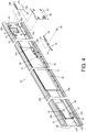
FIG. 4 is an exploded view of the first rail and related components of the slide rail assembly from the first viewing angle according to an embodiment of the present invention; -
FIG. 5 is an exploded view of the first rail and the related components of the slide rail assembly from a second viewing angle according to an embodiment of the present invention; -
FIG. 6 is a diagram showing the slide rail assembly being in a retracted state according to an embodiment of the present invention; -
FIG. 7 is an enlarged view of an area A ofFIG. 6 ; -
FIG. 8 is a diagram showing the first rail and a second rail of the slide rail assembly being synchronously moved relative to a third rail along a first direction according to an embodiment of the present invention; -
FIG. 9 is an enlarged view of an area A ofFIG. 8 ; -
FIG. 10 is a diagram showing the first rail and the second rail of the slide rail assembly being further moved relative to the third rail along the first direction according to an embodiment of the present invention; -
FIG. 11 is an enlarged view of an area A ofFIG. 10 ; -
FIG. 12 is a diagram showing the first rail of the slide rail assembly being located at an open position relative to the third rail, with the second rail being moved relative to the first rail along the first direction according to an embodiment of the present invention; -
FIG. 13 is a diagram showing the first rail of the slide rail assembly being located at the open position relative to the third rail, with the second rail being further moved relative to the first rail along the first direction according to an embodiment of the present invention; -
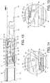
FIG. 14 is an enlarged view of an area A ofFIG. 13 ; -
FIG. 15 is an enlarged view of an area B ofFIG. 13 ; -
FIG. 16 is a diagram showing the first rail of the slide rail assembly being located at the open position relative to the third rail, with the second rail being further moved relative to the first rail along the first direction according to an embodiment of the present invention; -
FIG. 17 is an enlarged view of an area A ofFIG. 16 ; -
FIG. 18 is an enlarged view of an area B ofFIG. 16 ; -
FIG. 19 is a diagram showing the slide rail assembly being in an extended state according to an embodiment of the present invention; -
FIG. 20 is a diagram showing the first rail of the slide rail assembly being located at the open position relative to the third rail, with the second rail being moved relative to the first rail from an extension position along the first direction according to an embodiment of the present invention; -
FIG. 21 is a diagram showing the first rail of the slide rail assembly being located at the open position relative to the third rail, with the second rail being detached from the first rail along the first direction according to an embodiment of the present invention; -
FIG. 22 is an enlarged view of an area A ofFIG. 21 ; -
FIG. 23 is a diagram showing the first rail of the slide rail assembly being located at the open position relative to the third rail, with the second rail being mounted into a passage of the first rail along a second direction according to an embodiment of the present invention; -
FIG. 24 is an enlarged view of an area A ofFIG. 23 ; -
FIG. 25 is a diagram showing a blocking member of the first rail being located at a first position according to an embodiment of the present invention; -
FIG. 26 is a diagram showing an elastic member providing an elastic force to the blocking member to hold the blocking member at the first position according to an embodiment of the present invention; -
FIG. 27 is a diagram showing the blocking member of the first rail being located at a second position according to an embodiment of the present invention; -
FIG. 28 is a diagram showing the elastic member accumulating an elastic force in response to the blocking member of the first rail being located at the second position according to an embodiment of the present invention; -
FIG. 29 is a diagram showing the second rail of the slide rail assembly being moved relative to the first rail from the retracted position along the first direction, with an operating member adjacent to the blocking member at the first position according to an embodiment of the present invention; -
FIG. 30 is an enlarged view of an area A ofFIG. 29 ; -
FIG. 31 is a diagram showing the second rail of the slide rail assembly being further moved relative to the first rail along the first direction, with the operating member being configured to press the blocking member to hold the blocking member at the second position according to an embodiment of the present invention; -
FIG. 32 is an enlarged view of an area A ofFIG. 31 ; -
FIG. 33 is a diagram showing the second rail of the slide rail assembly being located at the extension position relative to the first rail according to an embodiment of the present invention; -
FIG. 34 is an enlarged view of an area A ofFIG. 33 ; -
FIG. 35 is a diagram showing a synchronization member of the first rail of the slide rail assembly being configured to be engaged with a functional member of the third rail according to an embodiment of the present invention; and -
FIG. 36 is a diagram showing a portion of the synchronization member of the first rail of the slide rail assembly being elastically extended toward the third rail according to an embodiment of the present invention. - As shown in
FIG. 1 andFIG. 2 , a slide rail assembly comprises a first rail 22 (such as a middle rail), a second rail 24 (such as an inner rail) and a blockingmember 26. Preferably, the slide rail assembly further comprises a third rail 28 (such as an outer rail). - The
third rail 28 comprises afirst wall 30a, asecond wall 30b and alongitudinal wall 32 connected between thefirst wall 30a and thesecond wall 30b of thethird rail 28. A passage is defined by thefirst wall 30a, thesecond wall 30b and thelongitudinal wall 32 of thethird rail 28 and configured to accommodate thefirst rail 22. Preferably, the slide rail assembly further comprises at least oneslide assisting kit 34 movably mounted between thethird rail 28 and thefirst rail 22 and configured to improve smoothness of relative movement between thethird rail 28 and thefirst rail 22. Theslide assisting kit 34 comprises a plurality ofslide assisting members 34a rollingly contacting thethird rail 28 and thefirst rail 22. Preferably, thelongitudinal wall 32 of thethird rail 28 is arranged with afunctional member 36, and thefirst rail 22 is arranged with asynchronization member 38. Preferably, thesynchronization member 38 is located adjacent to an end part (such as a rear end part) of thefirst rail 22. Thesynchronization member 38 is configured to interact with thefunctional member 36 to terminate synchronization relationship between thesecond rail 24 and thefirst rail 22. Thefunctional member 36 comprises a guidingstructure 40 and apositioning part 42. Preferably, the guidingstructure 40 has an inclined surface or an arc surface, and thepositioning part 42 has a groove or a recessed part. On the other hand, thesynchronization member 38 is pivoted to thefirst rail 22 through ashaft member 39, and thesynchronization member 38 comprises anelastic leg 38a and asynchronization structure 38b. - The
first rail 22 is movably mounted between thethird rail 28 and thesecond rail 24, and thefirst rail 22 is longitudinally movable relative to thethird rail 28. Thefirst rail 22 comprises afirst wall 44a, asecond wall 44b and alongitudinal wall 46 connected between thefirst wall 44a and thesecond wall 44b of thefirst rail 22. A passage is defined by thefirst wall 44a, thesecond wall 44b and thelongitudinal wall 46 of thefirst rail 22 and configured to accommodate thesecond rail 24. - The blocking
member 26 is movably arranged on thefirst rail 22. Preferably, the blockingmember 26 is located adjacent to the other end part (such as a front end part) of thefirst rail 22. - The
second rail 24 is longitudinally movable relative to thefirst rail 22. Thesecond rail 24 comprises afirst wall 48a, asecond wall 48b and alongitudinal wall 50 connected between thefirst wall 48a and thesecond wall 48b of thesecond rail 24. - Preferably, the slide rail assembly further comprises a first working
member 52, a second workingmember 54 and abase 56. - A space S is defined between the first working
member 52 and the second workingmember 54 in a longitudinal direction. The first workingmember 52 is movably mounted to thesecond rail 24. In the present embodiment, the first workingmember 52 is pivoted to thelongitudinal wall 50 of thesecond rail 24 through a first mountingmember 58. On the other hand, the second workingmember 54 is movably mounted to thesecond rail 24. In the present embodiment, the second workingmember 54 is pivoted to thelongitudinal wall 50 of thesecond rail 24 through a second mountingmember 60. Thebase 56 comprises a firstelastic part 56a and a secondelastic part 56b configured to respectively provide elastic forces to the first workingmember 52 and the second workingmember 54, in order to hold the first workingmember 52 and the second workingmember 54 in a first working state. - Preferably, the slide rail assembly further comprises a
first operating member 62 and asecond operating member 64 operatively connected to the first workingmember 52 and the second workingmember 54 respectively. - Preferably, the
first rail 22 is arranged with anengaging part 66 located adjacent to the front end part of thefirst rail 22. In the present embodiment, the engagingpart 66 is formed on a connectingmember 68, and the connectingmember 68 is fixed to thelongitudinal wall 46 of thefirst rail 22 through at least one fixingmember 69. The engagingpart 66 is transversely (laterally) protruded from thelongitudinal wall 46 of thefirst rail 22. However, in other embodiments, the engagingpart 66 can be integrally formed on thelongitudinal wall 46 of thefirst rail 22. The present invention is not limited thereto. - Preferably, the slide rail assembly further comprises a
slide assisting device 70 movably mounted between thefirst rail 22 and thesecond rail 24 and configured to improve smoothness of relative movement between thefirst rail 22 and thesecond rail 24. Theslide assisting device 70 comprises amain body 72, a plurality ofslide assisting members 74 and afastening member 76. The plurality ofslide assisting members 74 are arranged on themain body 72 and configured to rollingly contact thefirst rail 22 and thesecond rail 24. Thefastening member 76 is movably mounted to themain body 72 of theslide assisting device 70. - Preferably, the
fastening member 76 has anelastic feature 78. Theelastic feature 78 can be an elastic arm or a spring, but the present invention is not limited thereto. Theelastic feature 78 is configured to provide an elastic force to thefastening member 76 in order to hold thefastening member 76 in a first predetermined state. - As shown in
FIG. 3 ,FIG. 4 andFIG. 5 , the slide rail assembly further comprises anelastic member 80 configured to provide an elastic force to the blockingmember 26. Preferably, thelongitudinal wall 46 of thefirst rail 22 has afirst side 23a and asecond side 23b opposite to thefirst side 23a. Thefirst side 23a of thelongitudinal wall 46 of thefirst rail 22 is close to thesecond rail 24, and thesecond side 23b of thelongitudinal wall 46 of thefirst rail 22 is close to thethird rail 28. Thefirst rail 22 has an opening H communicated with thefirst side 23a and thesecond side 23b of thefirst rail 22. Furthermore, the blockingmember 26 is located at a position corresponding to the opening H. The blockingmember 26 comprises amain body 26a and a blockingpart 26b. The blockingpart 26b is bent from themain body 26a. Preferably, the blockingpart 26b is substantially perpendicularly connected to themain body 26a, and the blockingpart 26b is transversely (laterally) protruded relative to thelongitudinal wall 46 of thefirst rail 22 toward thefirst side 23a of thelongitudinal wall 46 of thefirst rail 22. - Preferably, the opening H of the
first rail 22 is surrounded by a plurality of walls, such as a firstabutting wall 82a and a secondabutting wall 82b. The firstabutting wall 82a and the secondabutting wall 82b are configured to support the blockingmember 26 in order to hold the blockingmember 26 at a predetermined mounting position. - Preferably, the connecting
member 68 and theelastic member 80 are respectively arranged on thefirst side 23a and thesecond side 23b of thelongitudinal wall 46 of thefirst rail 22. Theelastic member 80 has anelastic section 80a located at a position corresponding to the opening H. Preferably, themain body 26a of the blockingmember 26 is sandwiched between the connectingmember 68 and theelastic section 80a of theelastic member 80. Theelastic section 80a of theelastic member 80 is configured to provide an elastic force to the blockingmember 26 to hold the blockingpart 26b of the blockingmember 26 to extend toward thefirst side 23a of thelongitudinal wall 46 of thefirst rail 22. - Preferably, the
fastening member 76 is pivoted to themain body 72 of theslide assisting device 70 through apin member 84. Preferably, thefastening member 76 further comprises afastening section 86, and thepin member 84 is located between thefastening section 86 and theelastic feature 78. Theelastic feature 78 is configured to abut against a supportingstructure 88 of themain body 72 of theslide assisting device 70. The supportingstructure 88 can be a protrusion or a wall, but the present invention is not limited thereto. - Preferably, the
first rail 22 further has afirst hole 91 communicated with thefirst side 23a and thesecond side 23b of thefirst rail 22, and asecond hole 92 communicated with thefirst side 23a and thesecond side 23b of thefirst rail 22. Furthermore, thesynchronization member 38 is arranged on thesecond side 23b of thelongitudinal wall 46 of the first rail 22 (as shown inFIG. 5 ), and theelastic leg 38a and thesynchronization structure 38b of thesynchronization member 38 are located at positions respectively corresponding to thefirst hole 91 and thesecond hole 92. Preferably, theelastic leg 38a of thesynchronization member 38 is configured to abut against an inner wall W of thefirst hole 91, and thesynchronization structure 38b of thesynchronization member 38 is configured to pass through thesecond hole 92 to extend to thefirst side 23a of thelongitudinal wall 46 of the first rail 22 (as shown inFIG. 3 andFIG. 4 ) . Preferably, thesynchronization member 38 further comprises an engaging section 94 (as shown inFIG. 5 ), and theshaft member 39 is located between the engagingsection 94 and thesynchronization structure 38b. - As shown in
FIG. 6 and FIG. 7 , the slide rail assembly is in a retracted state. Thefirst rail 22 is retracted relative to thethird rail 28, and thesecond rail 24 is located at a retraced position R relative to thefirst rail 22. Moreover, the first workingmember 52, the second workingmember 54, thebase 56, thefirst operating member 62 and thesecond operating member 64 are omitted fromFIG. 6 . - The blocking
member 26 is located adjacent to the front end part of thefirst rail 22. Thefastening member 76 is spaced from the engagingpart 66. Theelastic feature 78 of thefastening member 76 is configured to abut against the supportingstructure 88 of theslide assisting device 70, and thefastening member 76 can be held in the first predetermined state X1 by the elastic force of theelastic feature 78. Preferably, theslide assisting device 70 further comprises a first limitingpart 96a and a second limitingpart 96b (as shown inFIG. 7 ). On the other hand, thefastening member 76 further comprises acontact part 98. Thecontact part 98 can be a protrusion or an extension leg, but the present invention is not limited thereto. Thecontact part 98 of thefastening member 76 is located between the first limitingpart 96a and the second limitingpart 96b, such that thefastening member 76 can be rotated relative to theslide assisting device 70 within a limited range. - The
synchronization member 38 is spaced from thefunctional member 36. Thesynchronization member 38 is configured to abut against the inner wall W of thefirst rail 22 through theelastic leg 38a to be held in an initial state Y1. Preferably, thesecond rail 24 has anauxiliary feature 100. Theauxiliary feature 100 can be a protrusion, but the present invention is not limited thereto. When thesynchronization member 38 is in the initial state Y1, theauxiliary feature 100 of thesecond rail 24 is configured to interact with thesynchronization member 38. - As shown in
FIG. 8 and FIG. 9 , when thesecond rail 24 is moved relative to thefirst rail 22 from the retracted position R along a first direction D1, thesecond rail 24 abuts against thesynchronization structure 38b of thesynchronization member 38 in the initial state Y1 through theauxiliary feature 100, such that thesecond rail 24 can drive thefirst rail 22 to synchronously move along the first direction D1. When thefirst rail 22 and thesecond rail 24 are synchronously moved to a predetermined position, the engagingsection 94 of thesynchronization member 38 is configured to contact the guidingstructure 40 of thefunctional member 36 of thethird rail 28. - As shown in
FIG. 10 and FIG. 11 , when thesecond rail 24 and thefirst rail 22 are synchronously moved a predetermined distance relative to thethird rail 28 along the first direction D1, the guidingstructure 40 of thefunctional member 36 is configured to terminate synchronization relationship between thesecond rail 24 and thefirst rail 22. - Moreover, a working force is generated when the engaging
section 94 of thesynchronization member 38 contacts the guidingstructure 40 of thefunctional member 36 of thethird rail 28, such that thesynchronization member 38 is rotated from the initial state Y1 to a non-initial state Y2 (such as being rotated from an initial position to another position) in response to the working force. In the meantime, theauxiliary feature 100 of thesecond rail 24 and thesynchronization structure 38b of thesynchronization member 38 are spaced from each other, in order to terminate synchronization relationship between thesecond rail 24 and thefirst rail 22. In addition, when thesynchronization member 38 is in the non-initial state Y2, theelastic leg 38a accumulates an elastic force. - As shown in
FIG. 12 , when thefirst rail 22 is moved relative to thethird rail 28 along the first direction D1 to an open position K, thesynchronization member 38 returns to the initial state Y1 from the non-initial state Y2 in response to the elastic force of theelastic leg 38a, such that the engagingsection 94 of thesynchronization member 38 is engaged with thepositioning part 42 of thefunctional member 36 to hold thefirst rail 22 at the open position K, in order to prevent thefirst rail 22 from being moved from the open position K along the first direction D1 or along a second direction D2 opposite to the first direction D1. - As shown in
FIG. 13, FIG. 14 and FIG. 15 , when thefirst rail 22 is located at the open position K relative to thethird rail 28, thesecond rail 24 can be further moved relative to thefirst rail 22 along the first direction D1. Moreover, when thesecond rail 24 is moved relative to thefirst rail 22 along the first direction D1, theslide assisting device 70 can also be moved along the first direction D1. Thefastening member 76 can be held in the first predetermined state X1 by the elastic force of the elastic feature 78 (as shown inFIG. 14 ). In addition, the first workingmember 52 and the second workingmember 54 are configured to be respectively held in the first working state S1 in response to the elastic forces of the firstelastic part 56a and the secondelastic part 56b. Moreover, during a process of thesecond rail 24 being moved relative to thefirst rail 22 along the first direction D1, the second workingmember 54 of thesecond rail 24 is configured to contact afirst end 27a of the blockingpart 26b of the blockingmember 26 of the first rail 22 (as shown inFIG. 15 ) to generate a working force. - In addition, as shown in
FIG. 13 and FIG. 14 , thefastening member 76 further comprises an auxiliary structure located between thepin member 84 and thefastening section 86, and the auxiliary structure has afirst guiding section 87a and asecond guiding section 87b at two sides. Each of thefirst guiding section 87a and thesecond guiding section 87b has an inclined surface or an arc surface. On the other hand, the base 56 further comprises afirst contact part 57 and asecond contact part 59. Each of thefirst contact part 57 and thesecond contact part 59 has an inclined surface or an arc surface, and thefirst contact part 57 and thesecond contact part 59 are configured to interact with thefirst guiding section 87a and thesecond guiding section 87b respectively. As such, during the process of thesecond rail 24 being moved relative to thefirst rail 22 along the first direction D1 or the second direction D2 opposite to the first direction D1, thebase 56 can easily cross thefastening member 76. Moreover, during the process of thesecond rail 24 being moved relative to thefirst rail 22 along the first direction D1, theslide assisting device 70 is also moved along the first direction D1. Thefastening member 76 is held in the first predetermined state X1 by the elastic force of theelastic feature 78, and thesecond guiding section 87b of thefastening member 76 is configured to contact thesecond contact part 59 of thebase 56. - As shown in
FIG. 16, FIG. 17 and FIG. 18 , during the process of thesecond rail 24 being further moved relative to thefirst rail 22 along the first direction D1, the second workingmember 54 of thesecond rail 24 is rotated to be no longer in the first working state S1 (such as switching from the first working state S1 to a second working state S2) due to the working force generated by the second workingmember 54 of thesecond rail 24 contacting the blockingmember 26 of thefirst rail 22, such that the second workingmember 54 can cross thefirst end 27a of the blockingmember 26. In the meantime, the secondelastic part 56b accumulates an elastic force (as shown inFIG. 18 ) . On the other hand, the first workingmember 52 is in the first working state S1 in response to the elastic force of the firstelastic part 56a (as shown inFIG. 17 ). - In addition, as shown in
FIG. 16 and FIG. 17 , during the process of thesecond rail 24 being further moved relative to thefirst rail 22 along the first direction D1, theslide assisting device 70 is also moved along the first direction D1. Thefastening member 76 contacts thesecond contact part 59 of the base 56 through thesecond guiding section 87b to generate a working force, such that thefastening member 76 is rotated to switch from the first predetermined state X1 to a second predetermined state X2. Moreover, alongitudinal section 61 of thebase 56 is configured to abut against the auxiliary structure of thefastening member 76 to temporarily hold thefastening member 76 in the second predetermined state X2. In the meantime, theelastic feature 78 of thefastening member 76 accumulates an elastic force. - As shown in
FIG. 19 , when thesecond rail 24 is further moved relative to thefirst rail 22 along the first direction D1 to an extension position E, thesecond rail 24 is blocked by the blockingmember 26. - For example, when the
second rail 24 is moved to the extension position E, the second workingmember 54 returns to the first working state S1 from the second working state S2 in response to the elastic force of the secondelastic part 56b. In the meantime, the second workingmember 54 is located adjacent to asecond end 27b of the blockingmember 26. On the other hand, the first workingmember 52 is in the first working state S1 and located adjacent to thefirst end 27a of the blockingmember 26. In other words, the first workingmember 52 and the second workingmember 54 are respectively located adjacent to two opposite ends of the blockingmember 26. According to such arrangement, thesecond rail 24 is configured to be blocked by thefirst end 27a of the blockingmember 26 through the first workingmember 52 in the first working state S1, in order to prevent thesecond rail 24 from being moved from the extension position E along the first direction D1; and thesecond rail 24 is configured to be blocked by thesecond end 27b of the blockingmember 26 through the second workingmember 54 in the first working state S1, in order to prevent thesecond rail 24 from being moved from the extension position E along the second direction D2. In the meantime, the slide rail assembly is in an extended state (such as being completely extended, but the present invention is not limited thereto) . Thefirst operating member 62 and thesecond operating member 64 are configured to be operated to respectively switch the first workingmember 52 and the second workingmember 54 from the first working state S1 to the second working state S2. - As shown in
FIG. 19 , when thesecond rail 24 is further moved relative to thefirst rail 22 along the first direction D1 to the extension position E, theslide assisting device 70 is also further moved along the first direction D1, and thefastening section 86 of thefastening member 76 in the second predetermined state X2 and theengaging part 66 of thefirst rail 22 are spaced from each other. - As shown in
FIG. 19 and FIG. 20 , when a user is going to move thesecond rail 24 relative to thefirst rail 22 from the extension position E along the first direction D1, the user can apply an operating force F to the first operating member 62 (as shown inFIG. 20 ) to drive a drivingpart 62a of thefirst operating member 62 to switch the first workingmember 52 from the first working state S1 to the second working state S2, such that thesecond rail 24 is no longer blocked by thefirst end 27a of the blockingpart 26b of the blockingmember 26, and thesecond rail 24 can be further moved from the extension position E along the first direction D1. - Moreover, as shown in
FIG. 20 , when thesecond rail 24 is moved relative to thefirst rail 22 from the extension position E along the first direction D1, theslide assisting device 70 is also moved along the first direction D1, and thefastening section 86 of thefastening member 76 in the second predetermined state X2 can cross theengaging part 66 of thefirst rail 22. - As shown in
FIG. 21 and FIG. 22 , when thesecond rail 24 is moved from the extension position E along the first direction D1, thesecond rail 24 can be detached from the passage of thefirst rail 22. During the process of thesecond rail 24 being moved relative to thefirst rail 22 from the extension position E along the first direction D1, theslide assisting device 70 is also moved along the first direction D1, and thelongitudinal section 61 of the base 56 no longer abuts against the auxiliary structure of thefastening member 76, such that thefastening member 76 is configured to return to the first predetermined state X1 in response to the elastic force of theelastic feature 78, so as to allow thefastening section 86 of thefastening member 76 to be engaged with the engagingpart 66 of thefirst rail 22. Preferably, the engagingpart 66 of thefirst rail 22 is located between thefastening section 86 and the auxiliary structure of thefastening member 76. According to such arrangement, theslide assisting device 70 can be temporarily held at such position. - As shown in
FIG. 23 and FIG. 24 , after thesecond rail 24 is detached from the first rail 22 (please refer toFIG. 21 ), thesecond rail 24 is configured to drive the fasteningmember 76 to detach from the engagingpart 66 of thefirst rail 22 through a guiding feature during a process of thesecond rail 24 being moved along the second direction D2 to be mounted into the passage of thefirst rail 22. Specifically, thesecond contact part 59 of thebase 56 is used as the guiding feature. Thesecond rail 24 pushes thesecond guiding section 87b of thefastening member 76 through thesecond contact part 59 of the base 56 to move thefastening member 76 to be no longer in the first predetermined state X1 (i.e. thefastening member 76 is switched from the first predetermined state X1 to the second predetermined state X2), such that thefastening member 76 can be detached from the engagingpart 66 of thefirst rail 22 to allow theslide assisting device 70 to move with thesecond rail 24 along the second direction D2. - As shown in
FIG. 25 and FIG. 26 , the blockingmember 26 is configured to be held at a first position P1 through the elastic force of theelastic member 80. The connectingmember 68 is arranged on thefirst side 23a of thelongitudinal wall 46 of the first rail 22 (as shown inFIG. 25 ), and theelastic member 80 is arranged on thesecond side 23b of thelongitudinal wall 46 of the first rail 22 (as show inFIG. 26 ). Preferably, themain body 26a of the blockingmember 26 is sandwiched between the connectingmember 68 and theelastic section 80a of theelastic member 80. The blockingmember 26 is configured to be held at the first position P1 through the elastic force of theelastic section 80a of theelastic member 80. - As shown in
FIG. 27 and FIG. 28 , the blockingmember 26 is movable relative to thefirst rail 22. For example, when a force M is applied to the blockingmember 26, the blockingmember 26 is transversely (laterally) moved a distance G from the first position P1 to a second position P2 (as shown inFIG. 27 ). In the meantime, theelastic section 80a of theelastic member 80 is slightly deformed to accumulate an elastic force (as shown inFIG. 28 ) . - As shown in
FIG. 29 to FIG. 32 , thesecond operating member 64 comprises a first pushingfeature 64a and a second pushingfeature 64b. Preferably, each of the first pushingfeature 64a and the second pushingfeature 64b has an inclined surface or an arc surface, and the first pushingfeature 64a and the second pushingfeature 64b are respectively arranged at two end parts of thesecond operating member 64. - Moreover, during the process of the
second rail 24 being moved relative to thefirst rail 22 from the retracted R along the first direction D1, thesecond operating member 64 is configured to press the blockingmember 26 to apply the force M through the first pushingfeature 64a to move the blockingmember 26 from the first position P1 (as shown inFIG. 30 ) to the second position P2 (as shown inFIG. 32 ). In the meantime, theelastic section 80a of theelastic member 80 is elastically deformed to accumulate an elastic force. - As shown in
FIG. 33 and FIG. 34 , when thesecond rail 24 is moved relative to thefirst rail 22 along the first direction D1 to the extension position E, the first workingmember 52 and the second workingmember 54 are respectively located adjacent to two ends of the blocking member 26 (pleaser refer toFIG. 19 ) . In the meantime, the blockingpart 26b of the blockingmember 26 is located at a position corresponding to the space S defined between the first workingmember 52 and the second workingmember 54, such that the blockingmember 26 returns to the first position P1 in response to the elastic force of theelastic section 80a of theelastic member 80. - Moreover, the
elastic member 80 provides the elastic force to the blockingmember 26 to transversely push the blockingmember 26 toward thelongitudinal wall 50 of thesecond rail 24. According to such arrangement, the blockingmember 26 can be transversely lifted and held at the first position P1 through the elastic force of theelastic member 80, such that the blockingmember 26 can have a greater transverse height T1 to be as close to thelongitudinal wall 50 of thesecond rail 24 as possible (for example, the transverse height T1 of the blockingmember 26 at the first position P1 is greater than one and a half of a thickness T2 of the workingmember member 26 is required to be as close to thelongitudinal wall 50 of thesecond rail 24 as possible through the elastic force of the elastic member 80). Therefore, reliability of the blockingpart 26b of the blockingmember 26 being engaged between the first and second workingmembers second rail 24 at the extension position E relative to thefirst rail 22. In addition, a limited transverse space defined between thelongitudinal wall 46 of thefirst rail 22 and thelongitudinal wall 50 of thesecond rail 24 of the slide rail assembly can also help the blockingmember 26 of thefirst rail 22 to be as close to thelongitudinal wall 50 of thesecond rail 24 as possible, such that the blockingmember 26 can be more effectively engaged between the first and second workingmembers - As shown in
FIG. 35 andFIG. 36 , thesynchronization member 38 is in the initial state Y1 in response to the elastic force released by theelastic leg 38a (please refer toFIG. 12 ), to allow the engagingsection 94 of thesynchronization member 38 to be engaged with thepositioning part 42 of thefunctional member 36. Moreover, thesynchronization member 38 can be made of a flexible material, and the engagingsection 94 of thesynchronization member 38 is elastically extended toward thelongitudinal wall 32 of thethird rail 28. Preferably, thesynchronization member 38 has aflexible arm 93 tilted toward thelongitudinal wall 32 of thethird rail 28, and the engagingsection 94 is arranged on theflexible arm 93. The engagingsection 94 of thesynchronization member 38 is configured to be close to or attached to thelongitudinal wall 32 of thethird rail 28 with assist of theflexible arm 93, in order to improve the engaging reliability between the engagingsection 94 of thesynchronization member 38 and thepositioning part 42 of thefunctional member 36. In addition, a limited transverse space defined between thelongitudinal wall 46 of thefirst rail 22 and thelongitudinal wall 32 of thethird rail 28 of the slide rail assembly can also help the engagingsection 94 of thesynchronization member 38 of thefirst rail 22 to be as close to thelongitudinal wall 32 of thethird rail 28 as possible, such that the engagingsection 94 of thesynchronization member 38 can be more effectively engaged with thepositioning part 42 of thefunctional member 36. Moreover, thefunctional member 36 is omitted fromFIG. 36 . - Therefore, the slide rail assembly according to the embodiments of the present invention is characterized in that:
- 1. The
slide assisting device 70 can be engaged with the engagingpart 66 of thefirst rail 22 through thefastening member 76, such that theslide assisting device 70 can be held at one position. Thefastening member 76 is movably mounted to theslide assisting device 70. - 2. The blocking
member 26 is movably arranged on the first rail 22 (such as the middle rail) . When thesecond rail 24 is moved relative to thefirst rail 22 from the retracted position R to the extension position E along the first direction D1, thesecond rail 24 is blocked by the blockingmember 26. Such arrangement can meet different requirements of the market, especially for an ultra-thin slide rail assembly. - 3. With the elastic force of the
elastic member 80, the blockingmember 26 can have the greater transverse height T1 to be as close to thesecond rail 24 as possible, such that the reliability of the blockingmember 26 being engaged between the first and second workingmembers second rail 24 at the extension position E relative to thefirst rail 22. - 4. The engaging
section 94 of thesynchronization member 38 is configured to be elastically extended toward thelongitudinal wall 32 of thethird rail 28 to improve the engaging reliability between the engagingsection 94 and thepositioning part 42 of thefunctional member 36.
Claims (15)
- A slide rail assembly, comprising:a first rail (22) arranged with an engaging part (66);a second rail (24) movable relative to the first rail (22); andcharacterized by:a slide assisting device (70) movably mounted between the first rail (22) and the second rail (24), wherein the slide assisting device (70) comprises a main body (72), a plurality of slide assisting members (74) and a fastening member (76), the plurality of slide assisting members (74) are arranged on the main body (72) and configured to rollingly contact the first rail (22) and the second rail (24), and the fastening member (76) is movably mounted to the main body (72);wherein the second rail (24) is movable relative to the first rail (22) from a retracted position to an extension position along a first direction; andwherein when the second rail (24) is moved from the extension position along the first direction, the slide assisting device (70) is configured to be engaged with the engaging part (66) of the first rail (22) through the fastening member (76) being in a predetermined state.
- The slide rail assembly of claim 1, further characterized by an elastic feature (78) configured to provide an elastic force to the fastening member (76) in order to hold the fastening member (76) in the predetermined state; wherein the fastening member (76) is pivoted to the main body (72) of the slide assisting device (70) .
- The slide rail assembly of claim 1 or 2, characterized in that after the second rail (24) is moved from the extension position along the first direction to be detached from the first rail (22), the second rail (24) is configured to drive the fastening member (76) to detach from the engaging part (66) of the first rail (22) through a guiding feature during a process of the second rail (24) being moved along a second direction opposite to the first direction to be mounted into the first rail (22).
- The slide rail assembly of any of claims 1-3, further characterized by a blocking member (26) movably arranged on the first rail (22); wherein when the second rail (24) is located at the extension position relative to the first rail (22), the second rail (24) is blocked by the blocking member (26).
- The slide rail assembly of claim 4, further characterized by an elastic member (80) configured to provide an elastic force to the blocking member (26).
- The slide rail assembly of claim 5, further characterized by a first working member (52) movably mounted to the second rail (24); wherein when the second rail (24) is located at the extension position, the second rail (24) is blocked by the blocking member (26) through the first working member (52) being in a first working state, in order to prevent the second rail (24) from being moved along the first direction.
- The slide rail assembly of claim 6, further characterized by a second working member (54) movably mounted to the second rail (24); wherein when the second rail (24) is located at the extension position, the second rail (24) is blocked by the blocking member (26) through the second working member (54) being in the first working state, in order to prevent the second rail (24) from being moved along a second direction opposite to the first direction.
- The slide rail assembly of claim 7, characterized in that the first working member (52) and the second working member (54) are pivoted to the second rail (24).
- The slide rail assembly of claim 8, further characterized by a first elastic part (56a) and a second elastic part (56b) configured to provide elastic forces to the first working member (52) and the second working member (54) respectively in order to hold the first working member (52) and the second working member (54) in the first working state; wherein the slide rail assembly further comprises a first operating member (62) and a second operating member (64) configured to be operated to respectively switch the first working member (52) and the second working member (54) from the first working state to a second working state.
- The slide rail assembly of any of claims 1-9, further characterized by a third rail (28), wherein the first rail (22) is movably mounted between the third rail (28) and the second rail (24) .
- The slide rail assembly of claim 10, further characterized by a slide assisting kit (34) movably mounted between the third rail (28) and the first rail (22); wherein the slide assisting kit (34) comprises a plurality of slide assisting members (34a) rollingly contacting the third rail (28) and the first rail (22) .
- The slide rail assembly of claim 10 or 11, characterized in that the third rail (28) is arranged with a functional member (36), and the first rail (22) is arranged with a synchronization member (38); wherein when the second rail (24) is moved relative to the first rail (22) from the retracted position along the first direction, the second rail (24) is configured to drive the first rail (22) to synchronously move along the first direction through the synchronization member (38); wherein a guiding structure (40) of the functional member (36) is configured to move the synchronization member (38) to allow the first rail (22) to be no longer synchronously moved with the second rail (24) when the second rail (24) is moved a predetermined distance from the retracted position along the first direction.
- The slide rail assembly of claim 12, characterized in that the synchronization member (38) is made of a flexible material.
- The slide rail assembly of claim 13, characterized in that the functional member (36) comprises a positioning part (42), and the synchronization member (38) comprises an engaging section (94) elastically extended toward the third rail (28); wherein when the first rail (22) is moved relative to the third rail (28) along the first direction to an open position, the first rail (22) is configured to be engaged with the positioning part (42) of the functional member (36) through the engaging section (94) of the synchronization member (38), in order to hold the first rail (22) at the open position.
- The slide rail assembly of claim 13 or 14, characterized in that the synchronization member (38) is pivoted to the first rail (22), and comprises an elastic leg (38a) abutting against the first rail (22).
Applications Claiming Priority (1)
| Application Number | Priority Date | Filing Date | Title |
|---|---|---|---|
| TW108125008A TWI702018B (en) | 2019-07-12 | 2019-07-12 | Slide rail assembly |
Publications (2)
| Publication Number | Publication Date |
|---|---|
| EP3763245A1 true EP3763245A1 (en) | 2021-01-13 |
| EP3763245B1 EP3763245B1 (en) | 2021-06-30 |
Family
ID=68468631
Family Applications (1)
| Application Number | Title | Priority Date | Filing Date |
|---|---|---|---|
| EP19207146.2A Active EP3763245B1 (en) | 2019-07-12 | 2019-11-05 | Slide rail assembly |
Country Status (4)
| Country | Link |
|---|---|
| US (1) | US10912382B2 (en) |
| EP (1) | EP3763245B1 (en) |
| JP (1) | JP6934036B2 (en) |
| TW (1) | TWI702018B (en) |
Families Citing this family (5)
| Publication number | Priority date | Publication date | Assignee | Title |
|---|---|---|---|---|
| CN114847691B (en) * | 2021-02-04 | 2023-11-24 | 川湖科技股份有限公司 | Sliding rail assembly |
| TWI765833B (en) * | 2021-10-20 | 2022-05-21 | 振躍精密滑軌股份有限公司 | Servo Slide Sync & Lock Mechanism |
| TWI827495B (en) * | 2023-03-29 | 2023-12-21 | 富世達股份有限公司 | Slide rail device |
| TWI835613B (en) * | 2023-03-29 | 2024-03-11 | 富世達股份有限公司 | Slide rail device |
| TWI862445B (en) * | 2024-04-12 | 2024-11-11 | 川湖科技股份有限公司 | Slide rail assembly |
Citations (6)
| Publication number | Priority date | Publication date | Assignee | Title |
|---|---|---|---|---|
| US4537450A (en) * | 1979-11-07 | 1985-08-27 | Jacmorr Manufacturing Limited | Three part slide |
| JP3063321U (en) * | 1999-04-23 | 1999-10-29 | 双葉金属工業株式会社 | Slide rail |
| US6851773B2 (en) | 2003-04-15 | 2005-02-08 | King Slide Works Co., Ltd. | Retaining structure for a slide-aiding member of a track device for a drawer |
| US7794029B2 (en) * | 2006-12-01 | 2010-09-14 | Hong-Fu Jin Precision Industry (ShenZhen) Co., Ltd. | Ball bearing slide assembly |
| EP3143901A1 (en) * | 2015-09-18 | 2017-03-22 | King Slide Works Co., Ltd. | Slide rail assembly |
| US9992906B2 (en) * | 2016-01-22 | 2018-06-05 | King Slide Works Co., Ltd. | Slide rail assembly and operation method thereof |
Family Cites Families (9)
| Publication number | Priority date | Publication date | Assignee | Title |
|---|---|---|---|---|
| US3904254A (en) * | 1973-06-14 | 1975-09-09 | Magnus F Hagen | Means for positioning ball retainer for telescoping ball bearing slide mechanisms in relationship to open or closed position of same |
| JPH0127712Y2 (en) * | 1985-11-27 | 1989-08-22 | ||
| US6145945A (en) | 1998-11-12 | 2000-11-14 | Accuride International, Inc. | Drawer slide bearing retainer and guide block |
| TW491055U (en) * | 2000-11-16 | 2002-06-11 | Kuo-Chan Weng | Positioning structure of ball bearing for extensible rail |
| US6655763B2 (en) | 2000-12-22 | 2003-12-02 | Jonathan Engineered Solutions | Controller for a quick disconnect slide assembly |
| US7798583B2 (en) | 2005-06-10 | 2010-09-21 | Central Industrial Supply Company | Detent pin bearing retainer lock for a drawer slide |
| US7780252B2 (en) * | 2007-02-16 | 2010-08-24 | Central Industrial Supply Company | Elongated staging lock for a drawer slide |
| JP5507215B2 (en) * | 2009-11-20 | 2014-05-28 | 富士ゼロックス株式会社 | Rail device, sheet member supply device, image forming apparatus |
| KR102496370B1 (en) * | 2016-03-07 | 2023-02-06 | 삼성전자주식회사 | Rail device and refrigerator having the smae |
-
2019
- 2019-07-12 TW TW108125008A patent/TWI702018B/en active
- 2019-10-07 US US16/594,376 patent/US10912382B2/en active Active
- 2019-11-05 EP EP19207146.2A patent/EP3763245B1/en active Active
- 2019-12-06 JP JP2019220809A patent/JP6934036B2/en active Active
Patent Citations (6)
| Publication number | Priority date | Publication date | Assignee | Title |
|---|---|---|---|---|
| US4537450A (en) * | 1979-11-07 | 1985-08-27 | Jacmorr Manufacturing Limited | Three part slide |
| JP3063321U (en) * | 1999-04-23 | 1999-10-29 | 双葉金属工業株式会社 | Slide rail |
| US6851773B2 (en) | 2003-04-15 | 2005-02-08 | King Slide Works Co., Ltd. | Retaining structure for a slide-aiding member of a track device for a drawer |
| US7794029B2 (en) * | 2006-12-01 | 2010-09-14 | Hong-Fu Jin Precision Industry (ShenZhen) Co., Ltd. | Ball bearing slide assembly |
| EP3143901A1 (en) * | 2015-09-18 | 2017-03-22 | King Slide Works Co., Ltd. | Slide rail assembly |
| US9992906B2 (en) * | 2016-01-22 | 2018-06-05 | King Slide Works Co., Ltd. | Slide rail assembly and operation method thereof |
Also Published As
| Publication number | Publication date |
|---|---|
| JP6934036B2 (en) | 2021-09-08 |
| TW202102162A (en) | 2021-01-16 |
| TWI702018B (en) | 2020-08-21 |
| US10912382B2 (en) | 2021-02-09 |
| US20210007480A1 (en) | 2021-01-14 |
| JP2021013720A (en) | 2021-02-12 |
| EP3763245B1 (en) | 2021-06-30 |
Similar Documents
| Publication | Publication Date | Title |
|---|---|---|
| EP3763247B1 (en) | Slide rail assembly | |
| EP3763246B1 (en) | Slide rail assembly | |
| EP3763245B1 (en) | Slide rail assembly | |
| EP3387952A1 (en) | Slide rail assembly | |
| EP3387949A1 (en) | Slide rail assembly | |
| US10278498B2 (en) | Bracket device and slide rail assembly comprising the same | |
| US9025323B2 (en) | Keyboard device, keyboard holding device and information input device | |
| EP3387950B1 (en) | Slide rail assembly | |
| WO2005096887A1 (en) | Stopper device for slide rail | |
| JP2022035949A (en) | Slide rail assembly | |
| US8422211B2 (en) | Assembling/disassembling keyboard structure for a portable device | |
| CN112237346B (en) | Sliding rail assembly | |
| CN112237345B (en) | Sliding rail assembly | |
| US20090165254A1 (en) | Housing of foldable device | |
| CN112240341A (en) | Sliding rail assembly | |
| JP4590200B2 (en) | Foldable mobile terminal | |
| JP4021257B2 (en) | Switch device | |
| JP4601721B1 (en) | Spring unit and slide mechanism | |
| JP5693341B2 (en) | Operating device | |
| CN112996332A (en) | Slide rail assembly and bracket driving mechanism thereof | |
| JP2004031109A (en) | Push button device |
Legal Events
| Date | Code | Title | Description |
|---|---|---|---|
| STAA | Information on the status of an ep patent application or granted ep patent |
Free format text: STATUS: EXAMINATION IS IN PROGRESS |
|
| PUAI | Public reference made under article 153(3) epc to a published international application that has entered the european phase |
Free format text: ORIGINAL CODE: 0009012 |
|
| 17P | Request for examination filed |
Effective date: 20200330 |
|
| AK | Designated contracting states |
Kind code of ref document: A1 Designated state(s): AL AT BE BG CH CY CZ DE DK EE ES FI FR GB GR HR HU IE IS IT LI LT LU LV MC MK MT NL NO PL PT RO RS SE SI SK SM TR |
|
| AX | Request for extension of the european patent |
Extension state: BA ME |
|
| RAP1 | Party data changed (applicant data changed or rights of an application transferred) |
Owner name: KING SLIDE TECHNOLOGY CO., LTD. Owner name: KING SLIDE WORKS CO., LTD. |
|
| RIN1 | Information on inventor provided before grant (corrected) |
Inventor name: CHEN, KEN-CHING Inventor name: WANG, CHUN-CHIANG Inventor name: YANG, SHUN-HO Inventor name: HUANG, CHIEN-LI |
|
| GRAP | Despatch of communication of intention to grant a patent |
Free format text: ORIGINAL CODE: EPIDOSNIGR1 |
|
| STAA | Information on the status of an ep patent application or granted ep patent |
Free format text: STATUS: GRANT OF PATENT IS INTENDED |
|
| INTG | Intention to grant announced |
Effective date: 20210316 |
|
| GRAS | Grant fee paid |
Free format text: ORIGINAL CODE: EPIDOSNIGR3 |
|
| GRAA | (expected) grant |
Free format text: ORIGINAL CODE: 0009210 |
|
| STAA | Information on the status of an ep patent application or granted ep patent |
Free format text: STATUS: THE PATENT HAS BEEN GRANTED |
|
| AK | Designated contracting states |
Kind code of ref document: B1 Designated state(s): AL AT BE BG CH CY CZ DE DK EE ES FI FR GB GR HR HU IE IS IT LI LT LU LV MC MK MT NL NO PL PT RO RS SE SI SK SM TR |
|
| REG | Reference to a national code |
Ref country code: CH Ref legal event code: EP |
|
| REG | Reference to a national code |
Ref country code: AT Ref legal event code: REF Ref document number: 1405528 Country of ref document: AT Kind code of ref document: T Effective date: 20210715 |
|
| REG | Reference to a national code |
Ref country code: DE Ref legal event code: R096 Ref document number: 602019005751 Country of ref document: DE |
|
| REG | Reference to a national code |
Ref country code: IE Ref legal event code: FG4D |
|
| REG | Reference to a national code |
Ref country code: LT Ref legal event code: MG9D |
|
| PG25 | Lapsed in a contracting state [announced via postgrant information from national office to epo] |
Ref country code: HR Free format text: LAPSE BECAUSE OF FAILURE TO SUBMIT A TRANSLATION OF THE DESCRIPTION OR TO PAY THE FEE WITHIN THE PRESCRIBED TIME-LIMIT Effective date: 20210630 Ref country code: FI Free format text: LAPSE BECAUSE OF FAILURE TO SUBMIT A TRANSLATION OF THE DESCRIPTION OR TO PAY THE FEE WITHIN THE PRESCRIBED TIME-LIMIT Effective date: 20210630 Ref country code: BG Free format text: LAPSE BECAUSE OF FAILURE TO SUBMIT A TRANSLATION OF THE DESCRIPTION OR TO PAY THE FEE WITHIN THE PRESCRIBED TIME-LIMIT Effective date: 20210930 |
|
| REG | Reference to a national code |
Ref country code: NL Ref legal event code: MP Effective date: 20210630 |
|
| REG | Reference to a national code |
Ref country code: AT Ref legal event code: MK05 Ref document number: 1405528 Country of ref document: AT Kind code of ref document: T Effective date: 20210630 |
|
| PG25 | Lapsed in a contracting state [announced via postgrant information from national office to epo] |
Ref country code: GR Free format text: LAPSE BECAUSE OF FAILURE TO SUBMIT A TRANSLATION OF THE DESCRIPTION OR TO PAY THE FEE WITHIN THE PRESCRIBED TIME-LIMIT Effective date: 20211001 Ref country code: LV Free format text: LAPSE BECAUSE OF FAILURE TO SUBMIT A TRANSLATION OF THE DESCRIPTION OR TO PAY THE FEE WITHIN THE PRESCRIBED TIME-LIMIT Effective date: 20210630 Ref country code: NO Free format text: LAPSE BECAUSE OF FAILURE TO SUBMIT A TRANSLATION OF THE DESCRIPTION OR TO PAY THE FEE WITHIN THE PRESCRIBED TIME-LIMIT Effective date: 20210930 Ref country code: RS Free format text: LAPSE BECAUSE OF FAILURE TO SUBMIT A TRANSLATION OF THE DESCRIPTION OR TO PAY THE FEE WITHIN THE PRESCRIBED TIME-LIMIT Effective date: 20210630 Ref country code: SE Free format text: LAPSE BECAUSE OF FAILURE TO SUBMIT A TRANSLATION OF THE DESCRIPTION OR TO PAY THE FEE WITHIN THE PRESCRIBED TIME-LIMIT Effective date: 20210630 |
|
| PG25 | Lapsed in a contracting state [announced via postgrant information from national office to epo] |
Ref country code: SM Free format text: LAPSE BECAUSE OF FAILURE TO SUBMIT A TRANSLATION OF THE DESCRIPTION OR TO PAY THE FEE WITHIN THE PRESCRIBED TIME-LIMIT Effective date: 20210630 Ref country code: PT Free format text: LAPSE BECAUSE OF FAILURE TO SUBMIT A TRANSLATION OF THE DESCRIPTION OR TO PAY THE FEE WITHIN THE PRESCRIBED TIME-LIMIT Effective date: 20211102 Ref country code: NL Free format text: LAPSE BECAUSE OF FAILURE TO SUBMIT A TRANSLATION OF THE DESCRIPTION OR TO PAY THE FEE WITHIN THE PRESCRIBED TIME-LIMIT Effective date: 20210630 Ref country code: RO Free format text: LAPSE BECAUSE OF FAILURE TO SUBMIT A TRANSLATION OF THE DESCRIPTION OR TO PAY THE FEE WITHIN THE PRESCRIBED TIME-LIMIT Effective date: 20210630 Ref country code: CZ Free format text: LAPSE BECAUSE OF FAILURE TO SUBMIT A TRANSLATION OF THE DESCRIPTION OR TO PAY THE FEE WITHIN THE PRESCRIBED TIME-LIMIT Effective date: 20210630 Ref country code: AT Free format text: LAPSE BECAUSE OF FAILURE TO SUBMIT A TRANSLATION OF THE DESCRIPTION OR TO PAY THE FEE WITHIN THE PRESCRIBED TIME-LIMIT Effective date: 20210630 Ref country code: ES Free format text: LAPSE BECAUSE OF FAILURE TO SUBMIT A TRANSLATION OF THE DESCRIPTION OR TO PAY THE FEE WITHIN THE PRESCRIBED TIME-LIMIT Effective date: 20210630 Ref country code: EE Free format text: LAPSE BECAUSE OF FAILURE TO SUBMIT A TRANSLATION OF THE DESCRIPTION OR TO PAY THE FEE WITHIN THE PRESCRIBED TIME-LIMIT Effective date: 20210630 Ref country code: SK Free format text: LAPSE BECAUSE OF FAILURE TO SUBMIT A TRANSLATION OF THE DESCRIPTION OR TO PAY THE FEE WITHIN THE PRESCRIBED TIME-LIMIT Effective date: 20210630 |
|
| PG25 | Lapsed in a contracting state [announced via postgrant information from national office to epo] |
Ref country code: PL Free format text: LAPSE BECAUSE OF FAILURE TO SUBMIT A TRANSLATION OF THE DESCRIPTION OR TO PAY THE FEE WITHIN THE PRESCRIBED TIME-LIMIT Effective date: 20210630 |
|
| REG | Reference to a national code |
Ref country code: DE Ref legal event code: R097 Ref document number: 602019005751 Country of ref document: DE |
|
| PG25 | Lapsed in a contracting state [announced via postgrant information from national office to epo] |
Ref country code: DK Free format text: LAPSE BECAUSE OF FAILURE TO SUBMIT A TRANSLATION OF THE DESCRIPTION OR TO PAY THE FEE WITHIN THE PRESCRIBED TIME-LIMIT Effective date: 20210630 |
|
| PLBE | No opposition filed within time limit |
Free format text: ORIGINAL CODE: 0009261 |
|
| STAA | Information on the status of an ep patent application or granted ep patent |
Free format text: STATUS: NO OPPOSITION FILED WITHIN TIME LIMIT |
|
| PG25 | Lapsed in a contracting state [announced via postgrant information from national office to epo] |
Ref country code: AL Free format text: LAPSE BECAUSE OF FAILURE TO SUBMIT A TRANSLATION OF THE DESCRIPTION OR TO PAY THE FEE WITHIN THE PRESCRIBED TIME-LIMIT Effective date: 20210630 |
|
| 26N | No opposition filed |
Effective date: 20220331 |
|
| PG25 | Lapsed in a contracting state [announced via postgrant information from national office to epo] |
Ref country code: MC Free format text: LAPSE BECAUSE OF FAILURE TO SUBMIT A TRANSLATION OF THE DESCRIPTION OR TO PAY THE FEE WITHIN THE PRESCRIBED TIME-LIMIT Effective date: 20210630 |
|
| PG25 | Lapsed in a contracting state [announced via postgrant information from national office to epo] |
Ref country code: LU Free format text: LAPSE BECAUSE OF NON-PAYMENT OF DUE FEES Effective date: 20211105 Ref country code: IT Free format text: LAPSE BECAUSE OF FAILURE TO SUBMIT A TRANSLATION OF THE DESCRIPTION OR TO PAY THE FEE WITHIN THE PRESCRIBED TIME-LIMIT Effective date: 20210630 Ref country code: BE Free format text: LAPSE BECAUSE OF NON-PAYMENT OF DUE FEES Effective date: 20211130 |
|
| REG | Reference to a national code |
Ref country code: BE Ref legal event code: MM Effective date: 20211130 |
|
| PG25 | Lapsed in a contracting state [announced via postgrant information from national office to epo] |
Ref country code: FR Free format text: LAPSE BECAUSE OF NON-PAYMENT OF DUE FEES Effective date: 20211130 |
|
| PG25 | Lapsed in a contracting state [announced via postgrant information from national office to epo] |
Ref country code: LT Free format text: LAPSE BECAUSE OF FAILURE TO SUBMIT A TRANSLATION OF THE DESCRIPTION OR TO PAY THE FEE WITHIN THE PRESCRIBED TIME-LIMIT Effective date: 20210630 |
|
| PG25 | Lapsed in a contracting state [announced via postgrant information from national office to epo] |
Ref country code: CY Free format text: LAPSE BECAUSE OF FAILURE TO SUBMIT A TRANSLATION OF THE DESCRIPTION OR TO PAY THE FEE WITHIN THE PRESCRIBED TIME-LIMIT Effective date: 20210630 |
|
| REG | Reference to a national code |
Ref country code: CH Ref legal event code: PL |
|
| PG25 | Lapsed in a contracting state [announced via postgrant information from national office to epo] |
Ref country code: LI Free format text: LAPSE BECAUSE OF NON-PAYMENT OF DUE FEES Effective date: 20221130 Ref country code: HU Free format text: LAPSE BECAUSE OF FAILURE TO SUBMIT A TRANSLATION OF THE DESCRIPTION OR TO PAY THE FEE WITHIN THE PRESCRIBED TIME-LIMIT; INVALID AB INITIO Effective date: 20191105 Ref country code: CH Free format text: LAPSE BECAUSE OF NON-PAYMENT OF DUE FEES Effective date: 20221130 |
|
| PG25 | Lapsed in a contracting state [announced via postgrant information from national office to epo] |
Ref country code: MK Free format text: LAPSE BECAUSE OF FAILURE TO SUBMIT A TRANSLATION OF THE DESCRIPTION OR TO PAY THE FEE WITHIN THE PRESCRIBED TIME-LIMIT Effective date: 20210630 |
|
| PG25 | Lapsed in a contracting state [announced via postgrant information from national office to epo] |
Ref country code: MT Free format text: LAPSE BECAUSE OF FAILURE TO SUBMIT A TRANSLATION OF THE DESCRIPTION OR TO PAY THE FEE WITHIN THE PRESCRIBED TIME-LIMIT Effective date: 20210630 |
|
| PGFP | Annual fee paid to national office [announced via postgrant information from national office to epo] |
Ref country code: GB Payment date: 20250909 Year of fee payment: 7 |
|
| PGFP | Annual fee paid to national office [announced via postgrant information from national office to epo] |
Ref country code: IE Payment date: 20250909 Year of fee payment: 7 |
|
| PG25 | Lapsed in a contracting state [announced via postgrant information from national office to epo] |
Ref country code: TR Free format text: LAPSE BECAUSE OF FAILURE TO SUBMIT A TRANSLATION OF THE DESCRIPTION OR TO PAY THE FEE WITHIN THE PRESCRIBED TIME-LIMIT Effective date: 20210630 |
|
| PGFP | Annual fee paid to national office [announced via postgrant information from national office to epo] |
Ref country code: DE Payment date: 20250910 Year of fee payment: 7 |