EP3763199A1 - Baler with removable sidewalls - Google Patents
Baler with removable sidewalls Download PDFInfo
- Publication number
- EP3763199A1 EP3763199A1 EP20183677.2A EP20183677A EP3763199A1 EP 3763199 A1 EP3763199 A1 EP 3763199A1 EP 20183677 A EP20183677 A EP 20183677A EP 3763199 A1 EP3763199 A1 EP 3763199A1
- Authority
- EP
- European Patent Office
- Prior art keywords
- plunger
- panel
- compression chamber
- distance
- frame
- Prior art date
- Legal status (The legal status is an assumption and is not a legal conclusion. Google has not performed a legal analysis and makes no representation as to the accuracy of the status listed.)
- Granted
Links
Images







Classifications
-
- A—HUMAN NECESSITIES
- A01—AGRICULTURE; FORESTRY; ANIMAL HUSBANDRY; HUNTING; TRAPPING; FISHING
- A01F—PROCESSING OF HARVESTED PRODUCE; HAY OR STRAW PRESSES; DEVICES FOR STORING AGRICULTURAL OR HORTICULTURAL PRODUCE
- A01F15/00—Baling presses for straw, hay or the like
- A01F15/04—Plunger presses
-
- A—HUMAN NECESSITIES
- A01—AGRICULTURE; FORESTRY; ANIMAL HUSBANDRY; HUNTING; TRAPPING; FISHING
- A01F—PROCESSING OF HARVESTED PRODUCE; HAY OR STRAW PRESSES; DEVICES FOR STORING AGRICULTURAL OR HORTICULTURAL PRODUCE
- A01F15/00—Baling presses for straw, hay or the like
- A01F15/04—Plunger presses
- A01F15/046—Plunger presses with press-boxes
-
- A—HUMAN NECESSITIES
- A01—AGRICULTURE; FORESTRY; ANIMAL HUSBANDRY; HUNTING; TRAPPING; FISHING
- A01F—PROCESSING OF HARVESTED PRODUCE; HAY OR STRAW PRESSES; DEVICES FOR STORING AGRICULTURAL OR HORTICULTURAL PRODUCE
- A01F15/00—Baling presses for straw, hay or the like
- A01F15/08—Details
Definitions
- the present disclosure relates to an agricultural baler having a compression chamber with removable sidewalls.
- a plunger reciprocates within a compression chamber to compress crop material and form bales.
- the movement of the plunger within the compression chamber exerts various forces against the sidewalls of the compression chamber causing them to wear and deform.
- the baler includes a frame having a first end, and a second end opposite the first end, a compression chamber where the compression chamber defines a central axis extending longitudinally therethrough, a plunger assembly at least partially positioned and movable within the compression chamber, and a panel removably coupled to the frame, and where the panel at least partially defines the compression chamber.
- the baler includes a frame having a first end, and a second end opposite the first end, a compression chamber at least partially defined by an interior surface, and where at least a portion of the interior surface is removable, and a plunger assembly at least partially positioned within and movable relative to the compression chamber.
- a baler including a frame, a plunger assembly including a plunger movable with respect to the frame between a first position and a second position to define a stroke region therebetween, and where the movement of the plunger between the first position and the second position defines a stroke axis, a compression chamber at least partially enclosing the stroke region, and wherein the compression chamber is at least partially defined by one or more panels, and where at least one of the one or more panels is movable relative to the frame.
- the disclosure relates to a baler, and more particularly to rectangular baler having a compression chamber defined by an interior surface that is at least partially removable. More specifically, the interior surface of the compression chamber is produced by one or more panels removably coupled to an underlying frame. During use, the user is able to remove and replace one or more of the panels as necessary to repair panels subject to excessive wear and/or damage caused by the baling process. By allowing the panels to be removed from the frame of the baler (e.g., using fasteners and the like), the user can better maintain the integrity of the compression chamber without having to cut into or significantly alter the underlying frame of the baler.
- FIG. 1 illustrates a large square baler 10 configured to collect and compress crop material 14 into individual, rectangular bales (not shown).
- the baler 10 includes a frame 22, one or more wheels 26 mounted on the frame 22, a feed system 30 coupled to the frame 22, and a compression system 34 to receive and compress crop material 14 provided by the feed system 30.
- the frame 22 of the baler 10 is generally formed from a series of interconnected rigid members and includes a first or front end 38 oriented generally in the direction of travel T, and a second or rear end 42 opposite the first end 38.
- the frame 22 also includes a tow bar 46 extending outwardly from the frame 22 from the first end 38 and connectable to a towing vehicle (not shown) such as an agricultural tractor or other vehicle. While the illustrated implementation is configured to be towed, it is to be understood that the baler may also be self-propelled.
- the feed system 30 of the baler 10 is configured to pick up crop material 14 from a support surface (not shown) and convey the crop material 14 to the compression system 34.
- the feed system 30 includes a pickup assembly 54 for receiving the crop material 14 from the support surface 50, and a delivery assembly 58 for directing the collected crop material 14 to the compression system 34.
- the compression system 34 includes a compression chamber 62 open to and configured to receive crop material from the feed system 30, a plunger assembly 66 at least partially positioned within the compression chamber 62 and configured to move with respect thereto, and a bale case 72.
- the compression system 34 also defines a longitudinal or central axis 68 extending along the length of the compression chamber 62 (e.g., parallel to the direction of travel T) and generally positioned at the cross-sectional center thereof.
- the plunger assembly 66 of the compression system 34 includes a rotational input or crank arm 70, a plunger 74 at least partially positioned within and movable with respect to the compression chamber 62, and one or more connecting rods 78 each extending between and coupled to both the crank arm 70 and the plunger 74 to transmit force therebetween.
- the crank arm 70 is configured to rotate about a crank axis 82 positioned proximate the first end 38 of the frame 22.
- the plunger 74 of the plunger assembly 66 includes a compression surface 86 configured to engage crop material 14 positioned within the compression chamber 62.
- the plunger 74 also defines a compression plane 88 aligned with the compression surface 86.
- the plunger 74 is positioned within and movable with respect to the compression chamber 62 between front-dead-center position (FDC) 90, in which the compression surface 86 of the plunger 74 is closest to the first end 38 of the frame 22 (e.g., the compression surface 86 is a first distance 94 from the first end 38), and a rear-dead-center position (RDC) 98 in which the compression surface 86 of the plunger 74 is positioned its furthest distance from the first end 38 (e.g., the compression surface 86 is a second distance 100 from the first end 38 greater than the first distance 94; see FIG.
- FDC front-dead-center position
- RDC rear-dead-center position
- the plunger 74 translates within the compression chamber 62 along the longitudinal axis 68 between the RDC 98 and FDC 90.
- the plunger 74 also defines a stroke length 102, defined as the distance between RDC 98 and FDC 90, and a plunger stroke region 106, defined as the volume of space located between RDC 98 and FDC 90.
- plunger assembly 66 uses a crank arm and connecting arm to produce the resulting reciprocating motion (described above), it is to be understood that in alternative implementations, alternative forms and types of drive assembly may be used to move the plunger 74 as described above.
- the compression chamber 62 of the baler 10 is at least partially defined by an interior surface 110. More specifically, the interior surface 110 includes a top surface 114, a bottom surface 118 opposite the top surface 114, and a pair of side surfaces 122 extending between the top surface 114 and the bottom surface 118. Together, the top, bottom, and side surfaces 114, 118, 122 define the compression chamber 62 as an elongated channel that is open on at least one end to the bale case 72 and that includes a substantially constant rectangular cross-sectional shape taken perpendicular to the longitudinal axis 68 (see FIG. 3 ). While the illustrated compression chamber 62 is substantially rectangular-prism in shape, in alternative implementations, other sizes and shapes of compression chamber 62 may be present.
- At least a portion of the interior surface 110 of the compression chamber 62 is removable in the form of one or more removable regions 126. As shown in FIG. 2 , at least a portion of the interior surface 110 enclosing the plunger stroke region 106 is removable. Each removable region 126, in turn, defines an axial length 130 measured along the longitudinal axis 68. In the illustrated implementation, the axial length 130 of at least one of the removable regions 126 is greater than the stroke length 102 of the plunger 74. Furthermore, the removable region 126 is positioned such that a first portion of the removable region 126 falls within the plunger stroke region 106, and a second portion of the removable region 126 falls outside the plunger stroke region 106 (see FIG. 2 ).
- the interior surface 110 of the present implementation is produced by one or more panels 134, 138, 142, each removably coupled to the frame 22. More specifically, the top surface 114 is generally produced by a top wall panel 134, the bottom surface 118 is generally produced by a bottom wall panel 138, and the side surfaces 122 are generally produced by a pair of side wall panels 142 (see FIG. 3 ).
- each panel 134, 138, 142 defines at least a portion of the interior surface 110 defining the plunger stroke region 106 such that a first portion of each panel 134, 138, 142 is positioned inside the stroke region 106 and a second portion of each panel 134, 138, 142 is positioned outside the stroke region 106.
- the panels 134, 138, 142 may be sized and shaped to correspond with relatively high-wear regions of the compression chamber 62.
- Such high-wear regions may include, but are not limited to, areas of the compression chamber 62 where the highest force load is exerted upon the interior surface 110 (e.g., the max load point), regions where the frictional sliding between the plunger 74 and interior surface 110 is highest (e.g., max wear point), and the like.
- the max wear point or region may be located near the RDC 98 as the friction against the interior surface 110 is proportional to the amount to which the crop is compressed.
- any one of the top, bottom, and/or side wall panels 134, 138, 142 may actually be formed from multiple adjacent and aligned panels (e.g., side by side) subdivided in the axial direction (e.g., along the longitudinal axis 68), the traverse direction (e.g., perpendicular to the longitudinal axis 68), or both.
- various sub-combinations of the multiple adjacent panels may be fixedly or removably coupled to the frame 22.
- one or more of the panels 134, 138, 142 may include a sub-panel (not shown) allowing a sub-region of the corresponding panel to be detached from the underlying panels 134, 138, 142.
- the location, size, and shape of the sub-regions forming the sub-panels may generally correspond with relatively high-wear regions of the compression chamber 62 (described above).
- Each wall panel 134, 138, 142 of the compression chamber 62 includes a substantially plate-like body (e.g., a steel plate) having a first surface 146 corresponding to and forming at least a portion of the interior surface 110, and a second surface 150 opposite the first surface 146.
- Each wall panel 134, 138, 142 also includes a leading edge or point 154, defined as the edge or point closest to the first end 38 of the frame 22, and a trailing edge or point 158 opposite the leading edge 154 and generally defined as the edge or point furthest from the first end 38. As shown in FIG.
- each wall panel 134, 138, 142 of the illustrated implementation is substantially quadrilateral in shape, it is to be understood that in alternative implementations one or more of the wall panels 134, 138, 142 may take on other shapes and sizes such as but not limited to rounded, polygonal, and the like.
- each wall panel 134, 138, 142 is positioned ahead of the FDC 90 position of the plunger 74 such that the leading edge 154 is not located within the stroke region 106 (e.g., the third distance 162 is less than the first distance 94; see FIGS. 7 and 8 ).
- the trailing edge 158 of each wall panel 134, 138, 142 is positioned behind of RDC 98 of the plunger 74 such that the trailing edge 158 is not located within the stroke region 106 (e.g., the fourth distance 166 is greater than the second distance 100; see FIGS. 9 and 10 ).
- the distance between the leading edge 154 and the trailing edge 158 define a longitudinal panel length 170 that is greater than the stroke length 102 of the plunger 74 (see FIG. 2 ).
- the edges 154, 158 of each wall panel 134, 138, 142 are positioned such that the compression surface 86 of the plunger 74 does not cross either edge 154, 158 while reciprocating between FDC 90 and RDC 98, thereby minimizing any potential damage to the plunger 74 or panels 134, 138, 142 during use.
- each wall panel 134, 138, 142 is substantially planar such that the first surface 146 defines a panel plane 174.
- the first surface 146 of one or more of the wall panels 134, 138, 142 may be contoured.
- At least one wall panel 134, 138, 142 is removably attached to the main frame 22 such that removing a panel 134, 138, 142 from the frame 22 removes a corresponding "removable region 126" from the interior surface 110. More specifically, the at least one wall panel 134, 138, 142 is removably coupled to the frame 22 by one or more fasteners 178 such as bolts, clips, quarter-turn fasteners, and the like (see FIGS. 2-10 ).
- the fasteners 178 are positioned proximate to and spaced along both the leading edge 154 and the trailing edge 158 such that the fasteners 178 are located outside the plunger stroke region 106 (e.g., between the first end 38 and FDC 90 or between the second end 42 and RDC 98; see FIGS. 8-10 ). As such, the compression plane 88 of the plunger 74 does not pass over the fasteners 178 when reciprocating between RDC 98 and FDC 90.
- the panels 134, 138, 142 are coupled to the frame 22 such that they are able move slightly along the panel plane 174 but cannot move perpendicular to the panel plane 174. Such movement allows for expansion and contraction within the panels 134, 138, 142 while not allowing the panels 134, 138, 142 to move into and out of the compression chamber 62 itself (e.g., the panels 134, 138, 142 cannot travel perpendicular to the longitudinal axis 68).
- the panels 134, 138, 142 may be completely fixed relative to the frame 22 when attached thereto.
- the compression system 34 also includes a first datum 182 (see FIG. 3 ).
- the first datum 182 includes a plane coincident with the longitudinal axis 68 and oriented substantially parallel to the bottom surface 118 (e.g., substantially horizontal).
- the side panels 142 are sized and shaped such that the first datum 182 passes therethrough.
- the compression system 34 also includes a second datum 186 that is coincident with the longitudinal axis 68 and oriented substantially perpendicular to the first datum 182 (e.g. substantially vertical).
- the top and bottom panels 134, 138 are sized and shaped such that the second datum 186 passes therethrough.
- each of the panels 134, 138, 142 of the illustrated implementation are removable from the frame 22, in alternative implementations only a subset of the panels may be removable (e.g., only the panels corresponding to the side walls are removable) while other panels are permanently fixed to the frame (e.g., welded, riveted, bonded, and the like).
- the plunger 74 reciprocates between the FDC 90 and RDC 98 as described above.
- a compression stroke e.g., when the plunger 74 moves from the FDC 90 toward the RDC 98
- crop material 14 is injected into the compression chamber 62 by the feed system 30 whereby it is compressed against a forming bale 190 located in the bale case 72.
- the density of the crop material 14 increases which also causes a corresponding increase in the frictional wear against the interior surface 110.
- the plunger 74 and crop material 14 reciprocally exert forces against the interior surface 110 of the compression chamber 62 as the crop material 14. Furthermore, the movement of the plunger 74 and crop material 14 along the interior surface 110 causes frictional wear on the panels 134, 138, 142.
- the user may remove the affected panels by detaching them from the frame 22 and replacing the removed panels with a corresponding replacement panel. By doing so, the user is able to maintain the compression chamber 62 without cutting into or significantly altering the frame 22.
- FIGS. 11-13 illustrate another embodiment of the plunger 74'.
- the plunger 74' is substantially similar to the plunger 74 illustrated in FIGS. 2-10 . As such, only the differences will be described herein.
- the plunger 74' includes a body 300' that defines one or more fastener channels 304' therein. More specifically, each fastener channel 304' is open to the exterior of the body 300' and positioned adjacent the interior surface 110 of the compression chamber 62 such that the channel 304' aligns with and at least partially receives at least one fastener 178 of the one or more fasteners 178 therein.
- the plunger 74' includes four fastener channels 304', with two channels 304' positioned on either side thereof and each corresponding with and configured to receive fasteners 178 coupling the side panels 142 to the frame 22 therein. While the illustrated implementation shows the channels 304' associated with the side panels 142, it is to be understood that additional channels (not shown) may also be present that correspond with the top panel 134 and/or the bottom panel 138.
- the fastener channel 304' is sized and shaped such that the corresponding fasteners 178 can enter and exit the channel 304' as the plunger 74' reciprocates between the FDC 90 and RDC 98 positions. More specifically, the channel 304' is shaped so that the fasteners 178 are positioned within the channel 304' when the plunger 74' is in the FDC 90 position (see FIG. 11 ). By doing so, the channel 304' provides access the fasteners 178 when the plunger 74' is in the FDC 90 position.
- the channel 304' permits the fasteners 178 positioned proximate both the leading edge 154 and the trailing edge 158 of the panel 142 to be accessed simultaneously and avoids the need to move the plunger 74' while detaching the corresponding panel.
- the plunger 74' also includes a surface panel 308' removably coupled to the body 300' and at least partially defining the compression surface 86'.
- the surface panel 308' is configurable in an attached position, in which the surface panel 308' is attached to the body 300' of the plunger 74' and restricting access to at least one of the fastener channels 304', and a detached position (see FIG. 11 ), in which the surface panel 308' is not attached to the body 300' and does not restrict access to the fastener channels 304'.
- the plunger 74' may include multiple surface panels (not shown) each defining a portion of the compression surface 86' and selectively providing access to a subset of fastener channels 304'.
- one or more surface panels 308' may be used in conjunction with a fixed compression surface portion that cannot be removed (not shown).
- FIGS. 14-20 illustrate another implementation of a side panel 142".
- the side panel 142" is substantially similar to the side panel 142 described above and therefore only the differences will be described herein.
- the side panel 142" includes a substantially plate-like body 400", a reinforcing rib 404" coupled to the body 400", one or more clip members 408" coupled to the rib 404", and one or more mounting brackets 412" configured to extend between and be selectively coupled to both the side panel 142" and the frame 22.
- the body 400" of the side panel 142" includes a first surface 416", configured to at least partially define a portion of the interior surface 110 of the compression chamber 62, and a second surface 420" opposite the first surface 416".
- the rib 404" of the side panel 142" is substantially elongated in shape and is coupled to the second surface 420" of the body 400" proximate the trailing edge 158". When assembled, the rib 404" is configured to strengthen the body 400" of the side panel 142" while also acting as a mounting location for the clip members 408" and mounting brackets 412" (described below).
- the rib 404" includes rectangular member having an end face 424", a first side face 428" extending from the end face 424", and a second side face 432" extending from the end face 424" opposite the first side face 428".
- the clip member 408" of the side panel 142" is configured to selectively engage and couple with a respective mounting bracket 412". More specifically, the clip member 408" is a substantially “S” shaped member having a first leg 436" extending therefrom. When assembled, the clip member 408" is coupled to the end face 424" of the rib 404" such that the first leg 436" is oriented substantially parallel to and spaced a distance from the end face 424" to form a gap 440" therebetween (see FIG. 16 ). While the illustrated implementation includes a separately formed clip member 408" coupled to the rib 404", in alternative implementation the clip member 408" and rib 404" may be integrally formed as a single unit.
- the mounting bracket 412" of the side panel 142" includes a body 444" having a first portion 448" configured to be releasably coupled to the rib 404" of the side panel 142", and a second portion 452" configured to be releasably coupled the frame 22 of the baler 10.
- the first portion 448" of the body 444" is a substantially C-shaped member forming a pocket 456" sized and shaped to receive at least a portion of the rib 404" therein (see FIG. 19 ). More specifically, the first portion 448" includes a first leg 460a", configured to correspond with and engage the first side face 428" of the rib 404", a second leg 460b" configured to correspond with and engage the end face 424" of the rib 404", and a third leg 460c" configured to correspond with and engage the second side face 432" of the rib 404". When assembled, the second leg 460b is also sized such that it can be at least partially positioned within the gap 440" formed between the clip member 408" and the rib 404" (see FIG. 16 ).
- the second portion 452" of the body 444" includes a mounting boss 464" defining a mounting aperture 468" configured to be placed in alignment with a corresponding aperture 472" of the frame 22.
- a fastener 476 e.g., a bolt and the like
- the user To attach the side panel 142" to the frame 22, the user first orients the panel 142" in the desired position relative to the compression chamber 62 (e.g., making sure the first surface 416" is properly located). Once in position, the user then introduces the rib 404" of the side panel 142" into the pocket 456" of the mounting bracket 412". The user continues to introduce the rib 404" into the pocket 456" until the first leg 460a" contacts the first side face 428", the third leg 460c" contacts the second side face 432", and the second leg 460b” contacts the end face 424" (see FIG. 18 ). The user may then slide the mounting bracket 412" along the length of the rib 404" until the second leg 460b" is at least partially located within the gap 440" formed between the rib 404" and the clip 408" (see FIG. 17 ).
- the user may then verify the alignment of the aperture 468" of the bracket 412" with the corresponding aperture 472" of the frame 22 and insert the fastener 476" therethrough.
- the panel 142" is secured and ready for baling operations.
- the user To remove a damaged or worn the side panel 142" from the frame 22, the user first unfastens the fastener 476" and removes it from both apertures 468", 472" (see FIG. 17 ). With the fastener 476" removed, the user then slides the mounting bracket 412" along the length of the rib 404" until the second leg 460b" is completely removed from the gap 440" (see FIG. 18 ). After the second leg 460b" is clear from the gap 440", the user may then completely detach the mounting bracket 412" from the rib 404" (e.g. remove the rib 404" from the pocket 456"; see FIG. 19 ). With the mounting bracket 412" completely removed, the user may remove the panel 142" from the frame 22 (see FIG. 20 .).
- top and/or bottom panels may also use a similar mounting mechanism.
- the illustrated implementation includes a single rib 404" located proximate the trailing edge 158" using two mounting brackets 412"; in alternative implementations, more or fewer mounting brackets 412" may be used. Still further, additional ribs 404" and additional brackets 412" may be present for any particular panel (not shown).
Landscapes
- Life Sciences & Earth Sciences (AREA)
- Environmental Sciences (AREA)
- Connection Of Plates (AREA)
- Harvester Elements (AREA)
Abstract
Description
- The present disclosure relates to an agricultural baler having a compression chamber with removable sidewalls.
- During operation of a square baler a plunger reciprocates within a compression chamber to compress crop material and form bales. During this process, the movement of the plunger within the compression chamber exerts various forces against the sidewalls of the compression chamber causing them to wear and deform.
- In one implementation the baler includes a frame having a first end, and a second end opposite the first end, a compression chamber where the compression chamber defines a central axis extending longitudinally therethrough, a plunger assembly at least partially positioned and movable within the compression chamber, and a panel removably coupled to the frame, and where the panel at least partially defines the compression chamber.
- In another implementation, the baler includes a frame having a first end, and a second end opposite the first end, a compression chamber at least partially defined by an interior surface, and where at least a portion of the interior surface is removable, and a plunger assembly at least partially positioned within and movable relative to the compression chamber.
- In another implementation, a baler including a frame, a plunger assembly including a plunger movable with respect to the frame between a first position and a second position to define a stroke region therebetween, and where the movement of the plunger between the first position and the second position defines a stroke axis, a compression chamber at least partially enclosing the stroke region, and wherein the compression chamber is at least partially defined by one or more panels, and where at least one of the one or more panels is movable relative to the frame.
- Other aspects of the disclosure will become apparent by consideration of the detailed description and accompanying drawings.
-
-
FIG. 1 is a perspective view of a large square baler with a compression chamber having one or more removable side walls. -
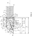
FIG. 2 is a cross-sectional schematic view of the baler ofFIG. 1 taken along a longitudinal axis of the compression chamber. -
FIG. 3 is a section view taken along line 3-3 ofFIG. 2 . -
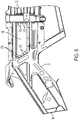
FIG. 4 is a perspective view of a frame of the large square baler ofFIG. 1 and two panels removed therefrom. -
FIG. 5 is a perspective view of the frame ofFIG. 4 with the two panels attached thereto. -
FIG. 6 is a side view of the frame and panels ofFIG. 5 . -
FIGS. 7 and 8 illustrate the frame and compression assembly ofFIG. 5 in a front dead center position. -
FIGS. 9 and 10 illustrate the frame and compression assembly ofFIG. 5 in the rear dead center position. -
FIGS 11-13 illustrate another implementation of the plunger of the compression assembly. -
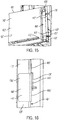
FIGS. 14-20 illustrate another implementation of a panel of the compression chamber. - Before any embodiments of the disclosure are explained in detail, it is to be understood that the disclosure is not limited in its application to the details of the formation and arrangement of components set forth in the following description or illustrated in the accompanying drawings. The disclosure is capable of supporting other implementations and of being practiced or of being carried out in various ways.
- The disclosure relates to a baler, and more particularly to rectangular baler having a compression chamber defined by an interior surface that is at least partially removable. More specifically, the interior surface of the compression chamber is produced by one or more panels removably coupled to an underlying frame. During use, the user is able to remove and replace one or more of the panels as necessary to repair panels subject to excessive wear and/or damage caused by the baling process. By allowing the panels to be removed from the frame of the baler (e.g., using fasteners and the like), the user can better maintain the integrity of the compression chamber without having to cut into or significantly alter the underlying frame of the baler.
-
FIG. 1 illustrates a largesquare baler 10 configured to collect and compress crop material 14 into individual, rectangular bales (not shown). Thebaler 10 includes aframe 22, one ormore wheels 26 mounted on theframe 22, afeed system 30 coupled to theframe 22, and a compression system 34 to receive and compress crop material 14 provided by thefeed system 30. - The
frame 22 of thebaler 10 is generally formed from a series of interconnected rigid members and includes a first orfront end 38 oriented generally in the direction of travel T, and a second orrear end 42 opposite thefirst end 38. Theframe 22 also includes atow bar 46 extending outwardly from theframe 22 from thefirst end 38 and connectable to a towing vehicle (not shown) such as an agricultural tractor or other vehicle. While the illustrated implementation is configured to be towed, it is to be understood that the baler may also be self-propelled. - As shown in
FIGS. 1 and2 , thefeed system 30 of thebaler 10 is configured to pick up crop material 14 from a support surface (not shown) and convey the crop material 14 to the compression system 34. In the illustrated implementation, thefeed system 30 includes a pickup assembly 54 for receiving the crop material 14 from the support surface 50, and a delivery assembly 58 for directing the collected crop material 14 to the compression system 34. - Referring now to
FIGS. 2-10 , the compression system 34 includes acompression chamber 62 open to and configured to receive crop material from thefeed system 30, aplunger assembly 66 at least partially positioned within thecompression chamber 62 and configured to move with respect thereto, and abale case 72. The compression system 34 also defines a longitudinal orcentral axis 68 extending along the length of the compression chamber 62 (e.g., parallel to the direction of travel T) and generally positioned at the cross-sectional center thereof. - The
plunger assembly 66 of the compression system 34 includes a rotational input orcrank arm 70, aplunger 74 at least partially positioned within and movable with respect to thecompression chamber 62, and one or more connectingrods 78 each extending between and coupled to both thecrank arm 70 and theplunger 74 to transmit force therebetween. As shown inFIG. 2 , thecrank arm 70 is configured to rotate about acrank axis 82 positioned proximate thefirst end 38 of theframe 22. - The
plunger 74 of theplunger assembly 66 includes acompression surface 86 configured to engage crop material 14 positioned within thecompression chamber 62. Theplunger 74 also defines acompression plane 88 aligned with thecompression surface 86. During use, theplunger 74 is positioned within and movable with respect to thecompression chamber 62 between front-dead-center position (FDC) 90, in which thecompression surface 86 of theplunger 74 is closest to thefirst end 38 of the frame 22 (e.g., thecompression surface 86 is afirst distance 94 from the first end 38), and a rear-dead-center position (RDC) 98 in which thecompression surface 86 of theplunger 74 is positioned its furthest distance from the first end 38 (e.g., thecompression surface 86 is asecond distance 100 from thefirst end 38 greater than thefirst distance 94; seeFIG. 2 ). In the illustrated implementation, theplunger 74 translates within thecompression chamber 62 along thelongitudinal axis 68 between theRDC 98 and FDC 90. Theplunger 74 also defines astroke length 102, defined as the distance betweenRDC 98 and FDC 90, and aplunger stroke region 106, defined as the volume of space located betweenRDC 98 and FDC 90. - While the illustrated
plunger assembly 66 uses a crank arm and connecting arm to produce the resulting reciprocating motion (described above), it is to be understood that in alternative implementations, alternative forms and types of drive assembly may be used to move theplunger 74 as described above. - Illustrated in
FIGS. 2 and3 , thecompression chamber 62 of thebaler 10 is at least partially defined by aninterior surface 110. More specifically, theinterior surface 110 includes atop surface 114, abottom surface 118 opposite thetop surface 114, and a pair ofside surfaces 122 extending between thetop surface 114 and thebottom surface 118. Together, the top, bottom, andside surfaces compression chamber 62 as an elongated channel that is open on at least one end to thebale case 72 and that includes a substantially constant rectangular cross-sectional shape taken perpendicular to the longitudinal axis 68 (seeFIG. 3 ). While the illustratedcompression chamber 62 is substantially rectangular-prism in shape, in alternative implementations, other sizes and shapes ofcompression chamber 62 may be present. - During use, at least a portion of the
interior surface 110 of thecompression chamber 62 is removable in the form of one or moreremovable regions 126. As shown inFIG. 2 , at least a portion of theinterior surface 110 enclosing theplunger stroke region 106 is removable. Eachremovable region 126, in turn, defines an axial length 130 measured along thelongitudinal axis 68. In the illustrated implementation, the axial length 130 of at least one of theremovable regions 126 is greater than thestroke length 102 of theplunger 74. Furthermore, theremovable region 126 is positioned such that a first portion of theremovable region 126 falls within theplunger stroke region 106, and a second portion of theremovable region 126 falls outside the plunger stroke region 106 (seeFIG. 2 ). - As shown in
FIGS. 2-10 , theinterior surface 110 of the present implementation is produced by one ormore panels frame 22. More specifically, thetop surface 114 is generally produced by atop wall panel 134, thebottom surface 118 is generally produced by abottom wall panel 138, and theside surfaces 122 are generally produced by a pair of side wall panels 142 (seeFIG. 3 ). In the illustrated implementation, eachpanel interior surface 110 defining theplunger stroke region 106 such that a first portion of eachpanel stroke region 106 and a second portion of eachpanel stroke region 106. In some implementations, thepanels compression chamber 62. Such high-wear regions may include, but are not limited to, areas of thecompression chamber 62 where the highest force load is exerted upon the interior surface 110 (e.g., the max load point), regions where the frictional sliding between theplunger 74 andinterior surface 110 is highest (e.g., max wear point), and the like. For example, the max wear point or region may be located near theRDC 98 as the friction against theinterior surface 110 is proportional to the amount to which the crop is compressed. - While the illustrated implementation includes four wall panels (e.g., one panel for each planar surface of the rectangular cross-sectional shape), in alternative implementations more or fewer panels may be present. For example, any one of the top, bottom, and/or
side wall panels frame 22. In other examples, one or more of thepanels underlying panels - Each
wall panel compression chamber 62 includes a substantially plate-like body (e.g., a steel plate) having afirst surface 146 corresponding to and forming at least a portion of theinterior surface 110, and asecond surface 150 opposite thefirst surface 146. Eachwall panel point 154, defined as the edge or point closest to thefirst end 38 of theframe 22, and a trailing edge orpoint 158 opposite theleading edge 154 and generally defined as the edge or point furthest from thefirst end 38. As shown inFIG. 2 , theleading edge 154 is located athird distance 162 from thefirst end 38 while the trailingedge 158 is located afourth distance 166 from thefirst end 38 greater than thethird distance 162. While eachwall panel wall panels - In the illustrated implementation, the
leading edge 154 of eachwall panel FDC 90 position of theplunger 74 such that theleading edge 154 is not located within the stroke region 106 (e.g., thethird distance 162 is less than thefirst distance 94; seeFIGS. 7 and 8 ). Similarly, the trailingedge 158 of eachwall panel RDC 98 of theplunger 74 such that the trailingedge 158 is not located within the stroke region 106 (e.g., thefourth distance 166 is greater than thesecond distance 100; seeFIGS. 9 and 10 ). Together, the distance between theleading edge 154 and the trailingedge 158 define alongitudinal panel length 170 that is greater than thestroke length 102 of the plunger 74 (seeFIG. 2 ). Stated differently, theedges wall panel compression surface 86 of theplunger 74 does not cross eitheredge FDC 90 andRDC 98, thereby minimizing any potential damage to theplunger 74 orpanels - In the illustrated implementation, the
first surface 146 of eachwall panel first surface 146 defines apanel plane 174. However, in alternative implementations, thefirst surface 146 of one or more of thewall panels - As shown in
FIG. 4 , at least onewall panel main frame 22 such that removing apanel frame 22 removes a corresponding "removable region 126" from theinterior surface 110. More specifically, the at least onewall panel frame 22 by one ormore fasteners 178 such as bolts, clips, quarter-turn fasteners, and the like (seeFIGS. 2-10 ). In the illustrated implementation, thefasteners 178 are positioned proximate to and spaced along both theleading edge 154 and the trailingedge 158 such that thefasteners 178 are located outside the plunger stroke region 106 (e.g., between thefirst end 38 andFDC 90 or between thesecond end 42 andRDC 98; seeFIGS. 8-10 ). As such, thecompression plane 88 of theplunger 74 does not pass over thefasteners 178 when reciprocating betweenRDC 98 andFDC 90. - In the illustrated implementation, the
panels frame 22 such that they are able move slightly along thepanel plane 174 but cannot move perpendicular to thepanel plane 174. Such movement allows for expansion and contraction within thepanels panels compression chamber 62 itself (e.g., thepanels panels frame 22 when attached thereto. - The compression system 34 also includes a first datum 182 (see
FIG. 3 ). Thefirst datum 182 includes a plane coincident with thelongitudinal axis 68 and oriented substantially parallel to the bottom surface 118 (e.g., substantially horizontal). As shown inFIG. 3 , theside panels 142 are sized and shaped such that thefirst datum 182 passes therethrough. The compression system 34 also includes asecond datum 186 that is coincident with thelongitudinal axis 68 and oriented substantially perpendicular to the first datum 182 (e.g. substantially vertical). As shown inFIG. 3 , the top andbottom panels second datum 186 passes therethrough. - While each of the
panels frame 22, in alternative implementations only a subset of the panels may be removable (e.g., only the panels corresponding to the side walls are removable) while other panels are permanently fixed to the frame (e.g., welded, riveted, bonded, and the like). - During operation of the
baler 10, theplunger 74 reciprocates between theFDC 90 andRDC 98 as described above. During a compression stroke (e.g., when theplunger 74 moves from theFDC 90 toward the RDC 98) crop material 14 is injected into thecompression chamber 62 by thefeed system 30 whereby it is compressed against a formingbale 190 located in thebale case 72. As theplunger 74 moves towardRDC 98, the density of the crop material 14 increases which also causes a corresponding increase in the frictional wear against theinterior surface 110. As the compression stroke is repeated, theplunger 74 and crop material 14 reciprocally exert forces against theinterior surface 110 of thecompression chamber 62 as the crop material 14. Furthermore, the movement of theplunger 74 and crop material 14 along theinterior surface 110 causes frictional wear on thepanels - When the wear or damage to one or more of the
panels frame 22 and replacing the removed panels with a corresponding replacement panel. By doing so, the user is able to maintain thecompression chamber 62 without cutting into or significantly altering theframe 22. -
FIGS. 11-13 illustrate another embodiment of the plunger 74'. The plunger 74' is substantially similar to theplunger 74 illustrated inFIGS. 2-10 . As such, only the differences will be described herein. The plunger 74' includes a body 300' that defines one or more fastener channels 304' therein. More specifically, each fastener channel 304' is open to the exterior of the body 300' and positioned adjacent theinterior surface 110 of thecompression chamber 62 such that the channel 304' aligns with and at least partially receives at least onefastener 178 of the one ormore fasteners 178 therein. In the illustrated implementation, the plunger 74' includes four fastener channels 304', with two channels 304' positioned on either side thereof and each corresponding with and configured to receivefasteners 178 coupling theside panels 142 to theframe 22 therein. While the illustrated implementation shows the channels 304' associated with theside panels 142, it is to be understood that additional channels (not shown) may also be present that correspond with thetop panel 134 and/or thebottom panel 138. - During use, the fastener channel 304' is sized and shaped such that the corresponding
fasteners 178 can enter and exit the channel 304' as the plunger 74' reciprocates between theFDC 90 andRDC 98 positions. More specifically, the channel 304' is shaped so that thefasteners 178 are positioned within the channel 304' when the plunger 74' is in theFDC 90 position (seeFIG. 11 ). By doing so, the channel 304' provides access thefasteners 178 when the plunger 74' is in theFDC 90 position. As such, the channel 304' permits thefasteners 178 positioned proximate both theleading edge 154 and the trailingedge 158 of thepanel 142 to be accessed simultaneously and avoids the need to move the plunger 74' while detaching the corresponding panel. - The plunger 74' also includes a surface panel 308' removably coupled to the body 300' and at least partially defining the compression surface 86'. During use, the surface panel 308' is configurable in an attached position, in which the surface panel 308' is attached to the body 300' of the plunger 74' and restricting access to at least one of the fastener channels 304', and a detached position (see
FIG. 11 ), in which the surface panel 308' is not attached to the body 300' and does not restrict access to the fastener channels 304'. While the illustrated implementation includes a single surface panel 308' defining the entire compression surface 86', in alternative implementations the plunger 74' may include multiple surface panels (not shown) each defining a portion of the compression surface 86' and selectively providing access to a subset of fastener channels 304'. In still other implementations, one or more surface panels 308' may be used in conjunction with a fixed compression surface portion that cannot be removed (not shown). -
FIGS. 14-20 illustrate another implementation of aside panel 142". Theside panel 142" is substantially similar to theside panel 142 described above and therefore only the differences will be described herein. Theside panel 142" includes a substantially plate-like body 400", a reinforcingrib 404" coupled to thebody 400", one ormore clip members 408" coupled to therib 404", and one or more mountingbrackets 412" configured to extend between and be selectively coupled to both theside panel 142" and theframe 22. As shown inFIG. 14 , thebody 400" of theside panel 142" includes afirst surface 416", configured to at least partially define a portion of theinterior surface 110 of thecompression chamber 62, and asecond surface 420" opposite thefirst surface 416". - The
rib 404" of theside panel 142" is substantially elongated in shape and is coupled to thesecond surface 420" of thebody 400" proximate the trailingedge 158". When assembled, therib 404" is configured to strengthen thebody 400" of theside panel 142" while also acting as a mounting location for theclip members 408" and mountingbrackets 412" (described below). In the illustrated implementation, therib 404" includes rectangular member having anend face 424", afirst side face 428" extending from theend face 424", and asecond side face 432" extending from theend face 424" opposite thefirst side face 428". - The
clip member 408" of theside panel 142" is configured to selectively engage and couple with arespective mounting bracket 412". More specifically, theclip member 408" is a substantially "S" shaped member having afirst leg 436" extending therefrom. When assembled, theclip member 408" is coupled to theend face 424" of therib 404" such that thefirst leg 436" is oriented substantially parallel to and spaced a distance from theend face 424" to form agap 440" therebetween (seeFIG. 16 ). While the illustrated implementation includes a separately formedclip member 408" coupled to therib 404", in alternative implementation theclip member 408" andrib 404" may be integrally formed as a single unit. - The mounting
bracket 412" of theside panel 142" includes abody 444" having afirst portion 448" configured to be releasably coupled to therib 404" of theside panel 142", and asecond portion 452" configured to be releasably coupled theframe 22 of thebaler 10. - The
first portion 448" of thebody 444" is a substantially C-shaped member forming apocket 456" sized and shaped to receive at least a portion of therib 404" therein (seeFIG. 19 ). More specifically, thefirst portion 448" includes afirst leg 460a", configured to correspond with and engage thefirst side face 428" of therib 404", asecond leg 460b" configured to correspond with and engage theend face 424" of therib 404", and athird leg 460c" configured to correspond with and engage thesecond side face 432" of therib 404". When assembled, thesecond leg 460b is also sized such that it can be at least partially positioned within thegap 440" formed between theclip member 408" and therib 404" (seeFIG. 16 ). - When the
first portion 448" is coupled to therib 404", the engagement of the first andthird legs 460a", 460c" engage the correspondingsurfaces 428", 432", respectively, of therib 404" and restrict relative motion between the mountingbracket 412" and therib 404" in a direction parallel to thelongitudinal axis 68 while still allowing thefirst portion 448" to slide along the length of therib 404". Similarly, the interaction between thesecond leg 460b", theend face 424", and theclip member 408" restrict relative motion between the mountingbracket 412" and therib 404" in a direction perpendicular to thelongitudinal axis 68 while still allowing thefirst portion 448" to slide along the length of therib 404". - The
second portion 452" of thebody 444" includes a mountingboss 464" defining a mountingaperture 468" configured to be placed in alignment with acorresponding aperture 472" of theframe 22. When the twoapertures 468", 472" are aligned, afastener 476" (e.g., a bolt and the like) may be passed through bothapertures 468", 472" to secure the mountingbracket 412" to theframe 22, causing the two elements to become spatially fixed relative to one another. - To attach the
side panel 142" to theframe 22, the user first orients thepanel 142" in the desired position relative to the compression chamber 62 (e.g., making sure thefirst surface 416" is properly located). Once in position, the user then introduces therib 404" of theside panel 142" into thepocket 456" of the mountingbracket 412". The user continues to introduce therib 404" into thepocket 456" until thefirst leg 460a" contacts thefirst side face 428", thethird leg 460c" contacts thesecond side face 432", and thesecond leg 460b" contacts theend face 424" (seeFIG. 18 ). The user may then slide the mountingbracket 412" along the length of therib 404" until thesecond leg 460b" is at least partially located within thegap 440" formed between therib 404" and theclip 408" (seeFIG. 17 ). - With the mounting
bracket 412" in location, the user may then verify the alignment of theaperture 468" of thebracket 412" with the correspondingaperture 472" of theframe 22 and insert thefastener 476" therethrough. Upon fastening thefastener 476", thepanel 142" is secured and ready for baling operations. - To remove a damaged or worn the
side panel 142" from theframe 22, the user first unfastens thefastener 476" and removes it from bothapertures 468", 472" (seeFIG. 17 ). With thefastener 476" removed, the user then slides the mountingbracket 412" along the length of therib 404" until thesecond leg 460b" is completely removed from thegap 440" (seeFIG. 18 ). After thesecond leg 460b" is clear from thegap 440", the user may then completely detach the mountingbracket 412" from therib 404" (e.g. remove therib 404" from thepocket 456"; seeFIG. 19 ). With the mountingbracket 412" completely removed, the user may remove thepanel 142" from the frame 22 (seeFIG. 20 .). - While the above implementation is illustrated relative to a
side panel 142", it is to be understood that in alternative implementations the top and/or bottom panels may also use a similar mounting mechanism. Furthermore, while the illustrated implementation includes asingle rib 404" located proximate the trailingedge 158" using two mountingbrackets 412"; in alternative implementations, more or fewer mountingbrackets 412" may be used. Still further,additional ribs 404" andadditional brackets 412" may be present for any particular panel (not shown). - Various features of the disclosure are set forth in the following claims.
Claims (15)
- A baler comprising:a frame having a first end, and a second end opposite the first end;a compression chamber at least partially defined by an interior surface, and wherein at least a portion of the interior surface is removable; anda plunger assembly at least partially positioned within and movable relative to the compression chamber.
- The baler of claim 1, further comprising a panel removably coupled to the frame, and wherein the panel at least partially defines the compression chamber.
- The baler of claim 1 or 2, wherein the plunger assembly includes a plunger, wherein the plunger reciprocates within the compression chamber between a first position, in which the plunger is positioned a first distance from the first end, and a second position, in which the plunger is positioned a second distance from the first end, wherein the plunger assembly defines a stroke length between the first position and the second position, wherein the panel defines a longitudinal length along the central axis, and wherein the axial length of the panel is greater than the stroke length.
- The baler according to at least one of the claims 1 to 3, wherein the plunger assembly includes a plunger, wherein the plunger reciprocates within the compression chamber between a first position, in which the plunger is positioned a first distance from the first end, and a second position, in which the plunger is positioned a second distance from the first end, wherein the plunger assembly defines a stroke length between the first position and the second position, wherein the panel defines a longitudinal length along the central axis, wherein the panel includes a first edge, and wherein the first edge is positioned a third distance from the first end that is less than the first distance.
- The baler according to at least one of the claims 1 to 4, wherein the panel includes a second edge, and wherein the second edge is positioned a fourth distance from the first end that is greater than the second distance.
- The baler according to at least one of the claims 1 to 5, wherein the panel is removably coupled to the frame with one or more fasteners.
- The baler according to at least one of the claims 1 to 6, wherein the plunger assembly includes a plunger, wherein the plunger reciprocates within the compression chamber between a first position, in which the plunger is positioned a first distance from the first end, and a second position, in which the plunger is positioned a second distance from the first end, wherein the panel is removably coupled to the frame with one or more fasteners, wherein the plunger defines a plunger stroke region between the first position and the second position, and wherein each fastener of the one or more fasteners is positioned outside the plunger stroke region.
- The baler according to at least one of the claims 1 to 7, further comprising a second panel removably coupled to the frame, and wherein the second panel at least partially defines the compression chamber.
- The baler according to at least one of the claims 1 to 8, wherein the panel defines a panel plane, and wherein when the panel is attached to the frame, the panel is movable along the panel plane but fixed perpendicular to the panel plane.
- The baler according to at least one of the claims 1 to 9, wherein the compression chamber defines a central axis, wherein the central axis is located at the cross-sectional center of the compression chamber, and wherein the baler includes a reference plane aligned with the central axis and oriented substantially horizontally, and wherein the reference plane passes through the panel.
- The baler according to at least one of the claims 1 to 10, wherein the interior surface includes a top wall, a bottom wall, and a pair of side walls extending between the top wall and the bottom wall.
- The baler according to at least one of the claims 1 to 11, wherein the plunger assembly includes a plunger, wherein the plunger reciprocates within the compression chamber between a first position, in which the plunger is positioned a first distance from the first end, and a second position, in which the plunger is positioned a second distance from the first end, wherein the plunger assembly defines a stroke length defined as the distance between the first position and the second position, wherein the portion of the interior surface that is removable forms a removable region, wherein the removable region has an axial length, and wherein axial length of the removable region is greater than the stroke length.
- The baler according to at least one of the claims 1 to 12, wherein the plunger assembly includes a plunger, wherein the plunger reciprocates within the compression chamber between a first position, in which the plunger is positioned a first distance from the first end, and a second position, in which the plunger is positioned a second distance from the first end, wherein the plunger assembly defines a stroke length defined as the distance between the first position and the second position, wherein the portion of the interior surface that is removable forms a removable region, and wherein the baler further defines a stroke region extending axially between the first position and the second position, and wherein at least a portion of the removable region is positioned outside the stroke region.
- The baler according to at least one of the claims 1 to 13, wherein the plunger assembly includes a plunger movable with respect to the frame between a first position and a second position to define a stroke region therebetween, and wherein the movement of the plunger between the first position and the second position defines a stroke axis;a. wherein the compression chamber at least partially encloses the stroke region, wherein the compression chamber is at least partially defined by one or more panels, and wherein at least one of the one or more panels is movable relative to the frame.
- The baler according to at least one of the claims 1 to 14, wherein each panel of the one or more panels is coupled to the frame.
Applications Claiming Priority (1)
| Application Number | Priority Date | Filing Date | Title |
|---|---|---|---|
| US16/509,358 US11197426B2 (en) | 2019-07-11 | 2019-07-11 | Baler with removable sidewalls |
Publications (2)
| Publication Number | Publication Date |
|---|---|
| EP3763199A1 true EP3763199A1 (en) | 2021-01-13 |
| EP3763199B1 EP3763199B1 (en) | 2023-06-21 |
Family
ID=71452134
Family Applications (1)
| Application Number | Title | Priority Date | Filing Date |
|---|---|---|---|
| EP20183677.2A Active EP3763199B1 (en) | 2019-07-11 | 2020-07-02 | Baler with removable sidewalls |
Country Status (2)
| Country | Link |
|---|---|
| US (1) | US11197426B2 (en) |
| EP (1) | EP3763199B1 (en) |
Citations (3)
| Publication number | Priority date | Publication date | Assignee | Title |
|---|---|---|---|---|
| DE4032393A1 (en) * | 1989-11-09 | 1991-05-16 | Fortschritt Erntemaschinen | Press channel for large bale baler - has side walls offset for easier access to plunger |
| CA2137715A1 (en) * | 1994-12-09 | 1996-06-10 | Leland W. Driggs | Low friction baler liner |
| US20030029331A1 (en) * | 2001-08-10 | 2003-02-13 | Jean-Francois Boucher | Baling chamber having adjustable cross section |
Family Cites Families (8)
| Publication number | Priority date | Publication date | Assignee | Title |
|---|---|---|---|---|
| US728516A (en) * | 1903-02-27 | 1903-05-19 | Paul Trabue | Tension-band for baling-presses. |
| US2596872A (en) * | 1951-04-13 | 1952-05-13 | Deere Mfg Co | Bale case extension for agricultural balers |
| US3424081A (en) * | 1966-01-10 | 1969-01-28 | Earl M Hoke | Bale compacting attachment for balers |
| US3487774A (en) * | 1967-06-19 | 1970-01-06 | Edward C Duerksen | Toy hay baler |
| US3985072A (en) | 1975-01-17 | 1976-10-12 | Lummus Industries, Inc. | Baling chamber construction |
| US4354430A (en) * | 1981-02-06 | 1982-10-19 | Sperry Corporation | Bale tension apparatus |
| GB8508004D0 (en) * | 1985-03-27 | 1985-05-01 | British Res Agricult Eng | Balers |
| US5461975A (en) * | 1994-06-16 | 1995-10-31 | Driggs; Leland W. | Low friction baler liner |
-
2019
- 2019-07-11 US US16/509,358 patent/US11197426B2/en active Active
-
2020
- 2020-07-02 EP EP20183677.2A patent/EP3763199B1/en active Active
Patent Citations (3)
| Publication number | Priority date | Publication date | Assignee | Title |
|---|---|---|---|---|
| DE4032393A1 (en) * | 1989-11-09 | 1991-05-16 | Fortschritt Erntemaschinen | Press channel for large bale baler - has side walls offset for easier access to plunger |
| CA2137715A1 (en) * | 1994-12-09 | 1996-06-10 | Leland W. Driggs | Low friction baler liner |
| US20030029331A1 (en) * | 2001-08-10 | 2003-02-13 | Jean-Francois Boucher | Baling chamber having adjustable cross section |
Also Published As
| Publication number | Publication date |
|---|---|
| EP3763199B1 (en) | 2023-06-21 |
| US11197426B2 (en) | 2021-12-14 |
| US20210007286A1 (en) | 2021-01-14 |
Similar Documents
| Publication | Publication Date | Title |
|---|---|---|
| CN102316717B (en) | Mechanism for applying pressure to a bale in a bale box of an agricultural baler | |
| CA2796165C (en) | Adjustable gaurd assembly for a sickle knife | |
| EP2232980B1 (en) | Modular baler plunger | |
| DE102009047585A1 (en) | Combination of a towing vehicle and a device | |
| EP3763199B1 (en) | Baler with removable sidewalls | |
| US9101091B2 (en) | Guide system for the plunger of a rectangular baler | |
| US8066116B2 (en) | Conveyor belt end connection | |
| US4750321A (en) | Sickle | |
| US2923230A (en) | Knife guided plunger for hay balers | |
| US5461975A (en) | Low friction baler liner | |
| US20040112030A1 (en) | Adjustable hold-down for sickle guards | |
| CN102395261B (en) | Agricultural baler with improved plunger guide | |
| US3943845A (en) | Replaceable feeder fingers for a baler | |
| US8757057B1 (en) | Baling machine | |
| US4516492A (en) | Bale discharge pressure plate | |
| US5363757A (en) | Method and apparatus for adjusting ram baler platen | |
| US4258540A (en) | Agricultural baler | |
| US7275358B2 (en) | Flexible trash guard for sickle bar mower | |
| US9468148B2 (en) | Feederhouse arrangement for mounting a header to a combine | |
| EP0745320A1 (en) | A bale press | |
| US9532507B2 (en) | Guide system for a plunger of a rectangular baler | |
| US6735931B1 (en) | Stud plate for sickle bar hold-down | |
| US11534998B2 (en) | Baling assembly with a support structure | |
| CN219124814U (en) | Novel beans harvester | |
| CN219403150U (en) | Automatic screw locking machine for handle of drag-lever box |
Legal Events
| Date | Code | Title | Description |
|---|---|---|---|
| PUAI | Public reference made under article 153(3) epc to a published international application that has entered the european phase |
Free format text: ORIGINAL CODE: 0009012 |
|
| STAA | Information on the status of an ep patent application or granted ep patent |
Free format text: STATUS: THE APPLICATION HAS BEEN PUBLISHED |
|
| AK | Designated contracting states |
Kind code of ref document: A1 Designated state(s): AL AT BE BG CH CY CZ DE DK EE ES FI FR GB GR HR HU IE IS IT LI LT LU LV MC MK MT NL NO PL PT RO RS SE SI SK SM TR |
|
| AX | Request for extension of the european patent |
Extension state: BA ME |
|
| STAA | Information on the status of an ep patent application or granted ep patent |
Free format text: STATUS: REQUEST FOR EXAMINATION WAS MADE |
|
| 17P | Request for examination filed |
Effective date: 20210713 |
|
| RBV | Designated contracting states (corrected) |
Designated state(s): AL AT BE BG CH CY CZ DE DK EE ES FI FR GB GR HR HU IE IS IT LI LT LU LV MC MK MT NL NO PL PT RO RS SE SI SK SM TR |
|
| GRAP | Despatch of communication of intention to grant a patent |
Free format text: ORIGINAL CODE: EPIDOSNIGR1 |
|
| RIC1 | Information provided on ipc code assigned before grant |
Ipc: A01F 15/08 19680901ALI20230105BHEP Ipc: A01F 15/04 19680901AFI20230105BHEP |
|
| STAA | Information on the status of an ep patent application or granted ep patent |
Free format text: STATUS: GRANT OF PATENT IS INTENDED |
|
| INTG | Intention to grant announced |
Effective date: 20230209 |
|
| GRAS | Grant fee paid |
Free format text: ORIGINAL CODE: EPIDOSNIGR3 |
|
| GRAA | (expected) grant |
Free format text: ORIGINAL CODE: 0009210 |
|
| STAA | Information on the status of an ep patent application or granted ep patent |
Free format text: STATUS: THE PATENT HAS BEEN GRANTED |
|
| AK | Designated contracting states |
Kind code of ref document: B1 Designated state(s): AL AT BE BG CH CY CZ DE DK EE ES FI FR GB GR HR HU IE IS IT LI LT LU LV MC MK MT NL NO PL PT RO RS SE SI SK SM TR |
|
| REG | Reference to a national code |
Ref country code: CH Ref legal event code: EP |
|
| REG | Reference to a national code |
Ref country code: DE Ref legal event code: R096 Ref document number: 602020012679 Country of ref document: DE |
|
| REG | Reference to a national code |
Ref country code: AT Ref legal event code: REF Ref document number: 1580204 Country of ref document: AT Kind code of ref document: T Effective date: 20230715 |
|
| REG | Reference to a national code |
Ref country code: IE Ref legal event code: FG4D |
|
| REG | Reference to a national code |
Ref country code: LT Ref legal event code: MG9D |
|
| REG | Reference to a national code |
Ref country code: NL Ref legal event code: MP Effective date: 20230621 |
|
| PG25 | Lapsed in a contracting state [announced via postgrant information from national office to epo] |
Ref country code: SE Free format text: LAPSE BECAUSE OF FAILURE TO SUBMIT A TRANSLATION OF THE DESCRIPTION OR TO PAY THE FEE WITHIN THE PRESCRIBED TIME-LIMIT Effective date: 20230621 Ref country code: NO Free format text: LAPSE BECAUSE OF FAILURE TO SUBMIT A TRANSLATION OF THE DESCRIPTION OR TO PAY THE FEE WITHIN THE PRESCRIBED TIME-LIMIT Effective date: 20230921 |
|
| REG | Reference to a national code |
Ref country code: AT Ref legal event code: MK05 Ref document number: 1580204 Country of ref document: AT Kind code of ref document: T Effective date: 20230621 |
|
| PG25 | Lapsed in a contracting state [announced via postgrant information from national office to epo] |
Ref country code: RS Free format text: LAPSE BECAUSE OF FAILURE TO SUBMIT A TRANSLATION OF THE DESCRIPTION OR TO PAY THE FEE WITHIN THE PRESCRIBED TIME-LIMIT Effective date: 20230621 Ref country code: NL Free format text: LAPSE BECAUSE OF FAILURE TO SUBMIT A TRANSLATION OF THE DESCRIPTION OR TO PAY THE FEE WITHIN THE PRESCRIBED TIME-LIMIT Effective date: 20230621 Ref country code: LV Free format text: LAPSE BECAUSE OF FAILURE TO SUBMIT A TRANSLATION OF THE DESCRIPTION OR TO PAY THE FEE WITHIN THE PRESCRIBED TIME-LIMIT Effective date: 20230621 Ref country code: LT Free format text: LAPSE BECAUSE OF FAILURE TO SUBMIT A TRANSLATION OF THE DESCRIPTION OR TO PAY THE FEE WITHIN THE PRESCRIBED TIME-LIMIT Effective date: 20230621 Ref country code: HR Free format text: LAPSE BECAUSE OF FAILURE TO SUBMIT A TRANSLATION OF THE DESCRIPTION OR TO PAY THE FEE WITHIN THE PRESCRIBED TIME-LIMIT Effective date: 20230621 Ref country code: GR Free format text: LAPSE BECAUSE OF FAILURE TO SUBMIT A TRANSLATION OF THE DESCRIPTION OR TO PAY THE FEE WITHIN THE PRESCRIBED TIME-LIMIT Effective date: 20230922 |
|
| PG25 | Lapsed in a contracting state [announced via postgrant information from national office to epo] |
Ref country code: FI Free format text: LAPSE BECAUSE OF FAILURE TO SUBMIT A TRANSLATION OF THE DESCRIPTION OR TO PAY THE FEE WITHIN THE PRESCRIBED TIME-LIMIT Effective date: 20230621 |
|
| PG25 | Lapsed in a contracting state [announced via postgrant information from national office to epo] |
Ref country code: SK Free format text: LAPSE BECAUSE OF FAILURE TO SUBMIT A TRANSLATION OF THE DESCRIPTION OR TO PAY THE FEE WITHIN THE PRESCRIBED TIME-LIMIT Effective date: 20230621 |
|
| PG25 | Lapsed in a contracting state [announced via postgrant information from national office to epo] |
Ref country code: ES Free format text: LAPSE BECAUSE OF FAILURE TO SUBMIT A TRANSLATION OF THE DESCRIPTION OR TO PAY THE FEE WITHIN THE PRESCRIBED TIME-LIMIT Effective date: 20230621 |
|
| PG25 | Lapsed in a contracting state [announced via postgrant information from national office to epo] |
Ref country code: IS Free format text: LAPSE BECAUSE OF FAILURE TO SUBMIT A TRANSLATION OF THE DESCRIPTION OR TO PAY THE FEE WITHIN THE PRESCRIBED TIME-LIMIT Effective date: 20231021 |
|
| PG25 | Lapsed in a contracting state [announced via postgrant information from national office to epo] |
Ref country code: SM Free format text: LAPSE BECAUSE OF FAILURE TO SUBMIT A TRANSLATION OF THE DESCRIPTION OR TO PAY THE FEE WITHIN THE PRESCRIBED TIME-LIMIT Effective date: 20230621 Ref country code: SK Free format text: LAPSE BECAUSE OF FAILURE TO SUBMIT A TRANSLATION OF THE DESCRIPTION OR TO PAY THE FEE WITHIN THE PRESCRIBED TIME-LIMIT Effective date: 20230621 Ref country code: RO Free format text: LAPSE BECAUSE OF FAILURE TO SUBMIT A TRANSLATION OF THE DESCRIPTION OR TO PAY THE FEE WITHIN THE PRESCRIBED TIME-LIMIT Effective date: 20230621 Ref country code: PT Free format text: LAPSE BECAUSE OF FAILURE TO SUBMIT A TRANSLATION OF THE DESCRIPTION OR TO PAY THE FEE WITHIN THE PRESCRIBED TIME-LIMIT Effective date: 20231023 Ref country code: IS Free format text: LAPSE BECAUSE OF FAILURE TO SUBMIT A TRANSLATION OF THE DESCRIPTION OR TO PAY THE FEE WITHIN THE PRESCRIBED TIME-LIMIT Effective date: 20231021 Ref country code: ES Free format text: LAPSE BECAUSE OF FAILURE TO SUBMIT A TRANSLATION OF THE DESCRIPTION OR TO PAY THE FEE WITHIN THE PRESCRIBED TIME-LIMIT Effective date: 20230621 Ref country code: EE Free format text: LAPSE BECAUSE OF FAILURE TO SUBMIT A TRANSLATION OF THE DESCRIPTION OR TO PAY THE FEE WITHIN THE PRESCRIBED TIME-LIMIT Effective date: 20230621 Ref country code: CZ Free format text: LAPSE BECAUSE OF FAILURE TO SUBMIT A TRANSLATION OF THE DESCRIPTION OR TO PAY THE FEE WITHIN THE PRESCRIBED TIME-LIMIT Effective date: 20230621 Ref country code: AT Free format text: LAPSE BECAUSE OF FAILURE TO SUBMIT A TRANSLATION OF THE DESCRIPTION OR TO PAY THE FEE WITHIN THE PRESCRIBED TIME-LIMIT Effective date: 20230621 |
|
| PG25 | Lapsed in a contracting state [announced via postgrant information from national office to epo] |
Ref country code: PL Free format text: LAPSE BECAUSE OF FAILURE TO SUBMIT A TRANSLATION OF THE DESCRIPTION OR TO PAY THE FEE WITHIN THE PRESCRIBED TIME-LIMIT Effective date: 20230621 |
|
| REG | Reference to a national code |
Ref country code: CH Ref legal event code: PL |
|
| PG25 | Lapsed in a contracting state [announced via postgrant information from national office to epo] |
Ref country code: MC Free format text: LAPSE BECAUSE OF FAILURE TO SUBMIT A TRANSLATION OF THE DESCRIPTION OR TO PAY THE FEE WITHIN THE PRESCRIBED TIME-LIMIT Effective date: 20230621 |
|
| REG | Reference to a national code |
Ref country code: BE Ref legal event code: MM Effective date: 20230731 |
|
| PG25 | Lapsed in a contracting state [announced via postgrant information from national office to epo] |
Ref country code: LU Free format text: LAPSE BECAUSE OF NON-PAYMENT OF DUE FEES Effective date: 20230702 |
|
| REG | Reference to a national code |
Ref country code: DE Ref legal event code: R097 Ref document number: 602020012679 Country of ref document: DE |
|
| PG25 | Lapsed in a contracting state [announced via postgrant information from national office to epo] |
Ref country code: MC Free format text: LAPSE BECAUSE OF FAILURE TO SUBMIT A TRANSLATION OF THE DESCRIPTION OR TO PAY THE FEE WITHIN THE PRESCRIBED TIME-LIMIT Effective date: 20230621 Ref country code: LU Free format text: LAPSE BECAUSE OF NON-PAYMENT OF DUE FEES Effective date: 20230702 |
|
| REG | Reference to a national code |
Ref country code: IE Ref legal event code: MM4A |
|
| PLBE | No opposition filed within time limit |
Free format text: ORIGINAL CODE: 0009261 |
|
| STAA | Information on the status of an ep patent application or granted ep patent |
Free format text: STATUS: NO OPPOSITION FILED WITHIN TIME LIMIT |
|
| PG25 | Lapsed in a contracting state [announced via postgrant information from national office to epo] |
Ref country code: DK Free format text: LAPSE BECAUSE OF FAILURE TO SUBMIT A TRANSLATION OF THE DESCRIPTION OR TO PAY THE FEE WITHIN THE PRESCRIBED TIME-LIMIT Effective date: 20230621 Ref country code: CH Free format text: LAPSE BECAUSE OF NON-PAYMENT OF DUE FEES Effective date: 20230731 |
|
| PG25 | Lapsed in a contracting state [announced via postgrant information from national office to epo] |
Ref country code: SI Free format text: LAPSE BECAUSE OF FAILURE TO SUBMIT A TRANSLATION OF THE DESCRIPTION OR TO PAY THE FEE WITHIN THE PRESCRIBED TIME-LIMIT Effective date: 20230621 |
|
| 26N | No opposition filed |
Effective date: 20240322 |
|
| PG25 | Lapsed in a contracting state [announced via postgrant information from national office to epo] |
Ref country code: SI Free format text: LAPSE BECAUSE OF FAILURE TO SUBMIT A TRANSLATION OF THE DESCRIPTION OR TO PAY THE FEE WITHIN THE PRESCRIBED TIME-LIMIT Effective date: 20230621 Ref country code: IT Free format text: LAPSE BECAUSE OF FAILURE TO SUBMIT A TRANSLATION OF THE DESCRIPTION OR TO PAY THE FEE WITHIN THE PRESCRIBED TIME-LIMIT Effective date: 20230621 Ref country code: BE Free format text: LAPSE BECAUSE OF NON-PAYMENT OF DUE FEES Effective date: 20230731 |
|
| PG25 | Lapsed in a contracting state [announced via postgrant information from national office to epo] |
Ref country code: IE Free format text: LAPSE BECAUSE OF NON-PAYMENT OF DUE FEES Effective date: 20230702 |
|
| PG25 | Lapsed in a contracting state [announced via postgrant information from national office to epo] |
Ref country code: IE Free format text: LAPSE BECAUSE OF NON-PAYMENT OF DUE FEES Effective date: 20230702 |
|
| PG25 | Lapsed in a contracting state [announced via postgrant information from national office to epo] |
Ref country code: BG Free format text: LAPSE BECAUSE OF FAILURE TO SUBMIT A TRANSLATION OF THE DESCRIPTION OR TO PAY THE FEE WITHIN THE PRESCRIBED TIME-LIMIT Effective date: 20230621 |
|
| PG25 | Lapsed in a contracting state [announced via postgrant information from national office to epo] |
Ref country code: BG Free format text: LAPSE BECAUSE OF FAILURE TO SUBMIT A TRANSLATION OF THE DESCRIPTION OR TO PAY THE FEE WITHIN THE PRESCRIBED TIME-LIMIT Effective date: 20230621 |
|
| GBPC | Gb: european patent ceased through non-payment of renewal fee |
Effective date: 20240702 |
|
| PG25 | Lapsed in a contracting state [announced via postgrant information from national office to epo] |
Ref country code: GB Free format text: LAPSE BECAUSE OF NON-PAYMENT OF DUE FEES Effective date: 20240702 |
|
| PG25 | Lapsed in a contracting state [announced via postgrant information from national office to epo] |
Ref country code: CY Free format text: LAPSE BECAUSE OF FAILURE TO SUBMIT A TRANSLATION OF THE DESCRIPTION OR TO PAY THE FEE WITHIN THE PRESCRIBED TIME-LIMIT; INVALID AB INITIO Effective date: 20200702 |
|
| PG25 | Lapsed in a contracting state [announced via postgrant information from national office to epo] |
Ref country code: HU Free format text: LAPSE BECAUSE OF FAILURE TO SUBMIT A TRANSLATION OF THE DESCRIPTION OR TO PAY THE FEE WITHIN THE PRESCRIBED TIME-LIMIT; INVALID AB INITIO Effective date: 20200702 |
|
| PGFP | Annual fee paid to national office [announced via postgrant information from national office to epo] |
Ref country code: DE Payment date: 20250620 Year of fee payment: 6 |
|
| PGFP | Annual fee paid to national office [announced via postgrant information from national office to epo] |
Ref country code: FR Payment date: 20250725 Year of fee payment: 6 |
|
| PG25 | Lapsed in a contracting state [announced via postgrant information from national office to epo] |
Ref country code: TR Free format text: LAPSE BECAUSE OF FAILURE TO SUBMIT A TRANSLATION OF THE DESCRIPTION OR TO PAY THE FEE WITHIN THE PRESCRIBED TIME-LIMIT Effective date: 20230621 |