EP3763109B1 - A method of configuring a storage system - Google Patents
A method of configuring a storage system Download PDFInfo
- Publication number
- EP3763109B1 EP3763109B1 EP19701736.1A EP19701736A EP3763109B1 EP 3763109 B1 EP3763109 B1 EP 3763109B1 EP 19701736 A EP19701736 A EP 19701736A EP 3763109 B1 EP3763109 B1 EP 3763109B1
- Authority
- EP
- European Patent Office
- Prior art keywords
- address
- panel controller
- panel
- controller
- command
- Prior art date
- Legal status (The legal status is an assumption and is not a legal conclusion. Google has not performed a legal analysis and makes no representation as to the accuracy of the status listed.)
- Active
Links
Images



Classifications
-
- G—PHYSICS
- G07—CHECKING-DEVICES
- G07F—COIN-FREED OR LIKE APPARATUS
- G07F17/00—Coin-freed apparatus for hiring articles; Coin-freed facilities or services
- G07F17/10—Coin-freed apparatus for hiring articles; Coin-freed facilities or services for means for safe-keeping of property, left temporarily, e.g. by fastening the property
- G07F17/12—Coin-freed apparatus for hiring articles; Coin-freed facilities or services for means for safe-keeping of property, left temporarily, e.g. by fastening the property comprising lockable containers, e.g. for accepting clothes to be cleaned
-
- H—ELECTRICITY
- H04—ELECTRIC COMMUNICATION TECHNIQUE
- H04L—TRANSMISSION OF DIGITAL INFORMATION, e.g. TELEGRAPHIC COMMUNICATION
- H04L61/00—Network arrangements, protocols or services for addressing or naming
- H04L61/50—Address allocation
- H04L61/5038—Address allocation for local use, e.g. in LAN or USB networks, or in a controller area network [CAN]
-
- A—HUMAN NECESSITIES
- A47—FURNITURE; DOMESTIC ARTICLES OR APPLIANCES; COFFEE MILLS; SPICE MILLS; SUCTION CLEANERS IN GENERAL
- A47B—TABLES; DESKS; OFFICE FURNITURE; CABINETS; DRAWERS; GENERAL DETAILS OF FURNITURE
- A47B88/00—Drawers for tables, cabinets or like furniture; Guides for drawers
- A47B88/40—Sliding drawers; Slides or guides therefor
- A47B88/453—Actuated drawers
- A47B88/457—Actuated drawers operated by electrically-powered actuation means
-
- G—PHYSICS
- G07—CHECKING-DEVICES
- G07F—COIN-FREED OR LIKE APPARATUS
- G07F11/00—Coin-freed apparatus for dispensing, or the like, discrete articles
- G07F11/02—Coin-freed apparatus for dispensing, or the like, discrete articles from non-movable magazines
- G07F11/04—Coin-freed apparatus for dispensing, or the like, discrete articles from non-movable magazines in which magazines the articles are stored one vertically above the other
- G07F11/16—Delivery means
- G07F11/18—Recessed drawers
-
- G—PHYSICS
- G07—CHECKING-DEVICES
- G07F—COIN-FREED OR LIKE APPARATUS
- G07F11/00—Coin-freed apparatus for dispensing, or the like, discrete articles
- G07F11/62—Coin-freed apparatus for dispensing, or the like, discrete articles in which the articles are stored in compartments in fixed receptacles
-
- G—PHYSICS
- G07—CHECKING-DEVICES
- G07F—COIN-FREED OR LIKE APPARATUS
- G07F17/00—Coin-freed apparatus for hiring articles; Coin-freed facilities or services
- G07F17/0092—Coin-freed apparatus for hiring articles; Coin-freed facilities or services for assembling and dispensing of pharmaceutical articles
-
- G—PHYSICS
- G07—CHECKING-DEVICES
- G07F—COIN-FREED OR LIKE APPARATUS
- G07F9/00—Details other than those peculiar to special kinds or types of apparatus
- G07F9/006—Details of the software used for the vending machines
-
- G—PHYSICS
- G07—CHECKING-DEVICES
- G07F—COIN-FREED OR LIKE APPARATUS
- G07F9/00—Details other than those peculiar to special kinds or types of apparatus
- G07F9/02—Devices for alarm or indication, e.g. when empty; Advertising arrangements in coin-freed apparatus
- G07F9/026—Devices for alarm or indication, e.g. when empty; Advertising arrangements in coin-freed apparatus for alarm, monitoring and auditing in vending machines or means for indication, e.g. when empty
-
- H—ELECTRICITY
- H04—ELECTRIC COMMUNICATION TECHNIQUE
- H04L—TRANSMISSION OF DIGITAL INFORMATION, e.g. TELEGRAPHIC COMMUNICATION
- H04L61/00—Network arrangements, protocols or services for addressing or naming
- H04L61/50—Address allocation
- H04L61/5046—Resolving address allocation conflicts; Testing of addresses
-
- H—ELECTRICITY
- H04—ELECTRIC COMMUNICATION TECHNIQUE
- H04L—TRANSMISSION OF DIGITAL INFORMATION, e.g. TELEGRAPHIC COMMUNICATION
- H04L67/00—Network arrangements or protocols for supporting network services or applications
- H04L67/01—Protocols
- H04L67/12—Protocols specially adapted for proprietary or special-purpose networking environments, e.g. medical networks, sensor networks, networks in vehicles or remote metering networks
- H04L67/125—Protocols specially adapted for proprietary or special-purpose networking environments, e.g. medical networks, sensor networks, networks in vehicles or remote metering networks involving control of end-device applications over a network
-
- H—ELECTRICITY
- H04—ELECTRIC COMMUNICATION TECHNIQUE
- H04L—TRANSMISSION OF DIGITAL INFORMATION, e.g. TELEGRAPHIC COMMUNICATION
- H04L67/00—Network arrangements or protocols for supporting network services or applications
- H04L67/34—Network arrangements or protocols for supporting network services or applications involving the movement of software or configuration parameters
-
- H—ELECTRICITY
- H05—ELECTRIC TECHNIQUES NOT OTHERWISE PROVIDED FOR
- H05K—PRINTED CIRCUITS; CASINGS OR CONSTRUCTIONAL DETAILS OF ELECTRIC APPARATUS; MANUFACTURE OF ASSEMBLAGES OF ELECTRICAL COMPONENTS
- H05K5/00—Casings, cabinets or drawers for electric apparatus
- H05K5/02—Details
- H05K5/0247—Electrical details of casings, e.g. terminals, passages for cables or wiring
-
- H—ELECTRICITY
- H05—ELECTRIC TECHNIQUES NOT OTHERWISE PROVIDED FOR
- H05K—PRINTED CIRCUITS; CASINGS OR CONSTRUCTIONAL DETAILS OF ELECTRIC APPARATUS; MANUFACTURE OF ASSEMBLAGES OF ELECTRICAL COMPONENTS
- H05K5/00—Casings, cabinets or drawers for electric apparatus
- H05K5/02—Details
- H05K5/0252—Labels, e.g. for identification, markings or configuration store
Definitions
- the present invention relates to configuring storage systems and other systems. In one aspect, it relates to setting up an address for storage units in electronic stock control systems well-known for use, for example, in manufacturing and medical facilities or as vending machines.
- a storage cabinet comprises a plurality of latched drawers held between panels fixed between support beams.
- Articles to be supplied to users are provided in the drawers or compartments of the drawers. Examples of such articles include cutting tools and the like used with machine tools; other manufacturing tools and components; drugs, needles and other medical items; and legal documents.
- a control system allows a user to access the required article by unlatching the drawer containing the required article. The drawer is then pulled out from the home position (where no compartments are exposed) to the extent that the compartment containing the article is exposed, when the drawer is latched again to prevent further opening of the drawer.
- each panel is centrally connected to a system controller which sends commands for both operation and maintenance of the panels.
- the panels in the same row are provided on the same bus and are addressed using multi-drop communications.
- the system controller broadcasts the same command to all the panels on the bus, but the command includes the address of the panel for which the command is intended.
- Each panel in such a system is addressed manually using a set of jumpers, in which a set of pins is connected to each other in a unique arrangement, to identify the panel. This makes the assembly process difficult and leads to problems when it is needed to replace the panel and use the same jumper arrangement as on the original panel. If a wrong jumper arrangement is used, it can be very hard to diagnose.
- IP 2010 040575 discloses a method for assigning an internet protocol (IP) address to a communication terminal e.g. electronic notebook, which involves displaying IP assigning addresses in response to an address resolution protocol (ARP) request when the terminal is in display mode.
- ARP address resolution protocol
- the communication terminal is switched between IP assigning mode and displaying mode by a control element.
- An address resolution protocol (ARP) request is acquired by the communication terminal when terminal is in IP assigning mode.
- the IP assigning addresses acquired in response to ARP request are displayed to user when the terminal is in display mode so that user is able to select one of the IP assigning addresses.
- the present invention has been made to address the problems of the prior art systems. According to the present invention, there are provided a method of configuring a storage system, a computer readable medium, an electronic unit for a storage cabinet, and an electronic storage system as defined in the appended claims.
- Fig. 1 the terms front, back, rear, left, right, top, bottom, upper, lower and like terms will be used consistently with the arrangement shown in Fig. 1 .
- the expression height corresponds to a dimension from top to bottom
- width corresponds to a dimension from left to right
- depth corresponds to a dimension from front to back.
- the terminology used in the description below is not limited to this.
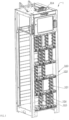
- Fig. 1 shows a perspective view of a storage system 1 according to the present invention.
- a housing 100 is provided with a frame comprising a plurality of panels 101 held upright between a plurality of support beams 102 extending in the width direction of the housing 100.
- the panels 101 and the support beams 102 are positioned such that several drawers (not shown) stacked on top of each other can be held between a pair of two adjacent panels 101.
- the system 1 has a modular design, therefore it is configurable to hold drawers of varied sizes.
- the panels 101 can be fixed at different points on the support beams 102 to accommodate drawers of single, double, or triple width and/or height.
- the housing 100 also has a system controller 104 mounted thereto. Cabling extends from the system controller 104 down channels provided in the front to circuitry provided in each of the panels 101. Although not shown, side and back plates would also be mounted to the housing 100 to prevent unauthorised access to the drawers and any control electronics.
- Each of the panels 101 is configured to have a plurality of guide blocks 105 on one side and corresponding support blocks 106 on the other side.
- a drawer is held between the guide block 105 on the right-hand side panel 101 and the support block 106 on the adjacent left-hand side panel 101.
- up to four standard size drawers can be held between two adjacent panels 101.
- the guide blocks 105 and the support blocks 106 can be adjusted to support larger size drawers.
- the panel 101 also includes a control mechanism to monitor when the drawer is in its fully closed position, the distance the drawer moves, and the direction of movement of the drawer.
- the control mechanism could comprise a solenoid-flap latch arrangement and a group of sensors, which is well-known in the art.
- the control mechanism is controlled by a panel controller 202 (as shown in Fig. 2 ) built into the panel 101.
- the panel controller 202 is connected to the system controller 104.
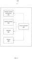
- Fig. 2 shows a block diagram of the panel 101.
- the panel 101 comprises a drawer control mechanism 201, a panel controller 202, an address button 203, an indicator 204, and a display 205.
- the drawer control mechanism 201 drives the drawers as explained above.
- Various components of the panel controller 202 and the address button 203 are explained later in the description.
- the indicator 204 is a visual, audio, or an audio-visual means provided on the panel 101 to indicate an operational state of the panel 101 to a user.
- the indicator 204 is a group of LEDs which are configured to change state and/or colour based on a signal received from the panel controller 202 and/or the system controller 104.
- the indicator 204 is a 4-digit binary LED display capable of displaying 16 unique binary codes.
- the display 205 is an optional screen on the panel 101 to display operating instructions and/or system messages to the user.
- the display 205 could be an LED or LCD screen.
- the display 205 could be a touch screen, like that on smartphones and tablets, and can serve the functions of both the indicator 204 and the address button 203. Where provided, the display 205 can be provided in addition to or instead of the indicator 204.
- Fig. 3 shows main components of the panel controller 202.
- the panel controller 202 is implemented by a standard microprocessor or a microcontroller well-known in the art, which is provided with working RAM (not shown or included in memory 303 discussed below).
- the panel controller 202 includes a communication module 301, an address handler 302, memory 303, and other modules 304.
- the communication module 301 is configured to communicate with the system controller 104.
- the communication module 301 receives and optionally acknowledges any signal or command sent by the system controller 104 to the panel controller 202.
- the communication module 301 may also report an incidence or send a service request to the system controller 104. For example, if the panel controller 202 detects a malfunctioning module, it can inform the system controller 104 by sending a message via the communication module 301.
- the communication between the panel controller 202 and the system controller 104 could be either wired or wireless.
- the address handler 302 manages the address assignment to the panel 101 from the system controller 104.
- the panels 101 do not have any address assigned to them or they are all assigned a default address, for example, "0000" so that any panel 101 can be fitted at any location in the system 1. This makes the assembling process quicker and easier.
- each panel 101 is assigned a unique address by the system controller 104.
- the address handler 302 can be invoked by a command generated by the system controller 104 upon system start-up after assembly. The address can then be set-up for a desired panel 101 by pressing the address button 203 on the panel 101.
- the address button 203 is an example of a sensor that can be actuated by a user and can be, but is not limited to, a hard push button, a soft touch button or a touchscreen on the panel 101.
- the address button 203 could be located at any convenient location on the panel 101.
- the memory 303 is implemented by a memory technology such as an EEPROM which can be reprogrammed several thousand times as and when needed.
- the address handler 302 Upon completion of address set-up for the panel 101, the address handler 302 records the assigned address for the panel 101 to the memory 303.
- the memory 303 may also include a working memory (RAM) for the controller microprocessor, which operates in accordance with application code permanently stored in the panel controller 202.
- the application is stored in nonvolatile flash memory at the manufacturing stage.
- the other modules 304 in the panel controller 202 are indicator controller, maintenance module, and the like.
- the indicator controller controls and monitors the state of the indicator 204 in response to commands from the system controller 104 and/or the pressing of the address button 203 on the panel 101.
- the maintenance module monitors the functioning of all other modules in the panel controller 202 and reports any issue to the system controller 104 and optionally to the user by means of the indicator 204 and/or the display 205.
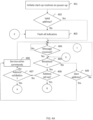
- Figs. 4A-4C show flow diagrams for a process 400 followed by each of the panel controllers 202 for configuring the respective panels 101 in the system 1.
- the panel controller 202 initiates start-up routines which may include testing for proper functioning of all components in the panel 101 and checking an address state of the panel 101.
- the panel controller 202 checks if a valid address is associated with the panel 101. During initial set-up, no address (or a default address) is associated with the panels 101, which the panel controller 202 would not recognise as a valid address.
- the panel controller 202 flashes all indicators 204 on the panel 101 if the panel does not have an address or only has the initial default address stored. Flashing of the indicators 204 signals to the user that no valid address has been set-up for the panel 101. Where the indicator 204 comprises several LEDs, all or a specific one of them may be flashed. Optionally, the display 205 may display a message for the user such as "no valid address exists.” However, if a valid address already exists for the panel 101, the panel controller 202 skips step S403.
- the panel controller 202 checks if a message is received from the system controller 104.
- the communication module 301 in the panel controller 202 keeps checking for any incoming communication from the system controller 104.
- the panel controllers 202 on all of the panels 101 receive all commands (which includes messages and other signals) from the system controller 104.
- Commands or messages can be global broadcast commands intended for all panels (which are called broadcast commands in the present specification) or commands or other messages intended for specific panels (which are called non-broadcast commands in the present specification - even though they are received by all panels, not all panels act on them). Both global broadcast (broadcast) message formats and panel-level (non-broadcast) message formats are hard-coded methods of addressing multiple panels.
- the panel controller 202 determines if the message received is a broadcast command, which is a command intended for all panel controllers 202 in the system.
- the panel controller 202 at step S406 determines if the command is for address set-up - that is, whether the command is what may be called an enumerate command. If it is, the process proceeds to step S410 explained later with reference to Fig. 4B . However, if the command is not for address set-up, the panel controller 202 at step S407 checks if the command is for address validation. Address validation is a command issued by the system controller 104 to check the validity of an address in view of existing addresses on the panels 101. If the command is determined to be for address validation, the process proceeds to step S416 explained later with reference to Fig. 4C . However, if the command is not for address validation then the panel controller 202 at step S408 services any other command issued by the system controller 104 in the message. This could be a routine health-check or system monitoring command.
- step S405 the panel controller 202 determines that the message received from the system controller 104 is not a broadcast command (that is, it is a non-broadcast command), it proceeds to step S409.
- Non-broadcast messages from the system controller 104 can include an address of a specific panel 101 preceding an instruction for the panel to follow.
- step S409 the panel controller 202 checks if the message comprises its own address. If the message is addressed to the panel 101, it services the command contained in the message at step S408 as described above. However, if the message does not include the address of the panel 101, the panel controller 202 simply ignores the message, returns to step S404 and continues to check for messages from the system controller 104.
- Fig. 4B shows an address set-up process following on from step S406 in Fig. 4A .
- the panel controller 202 displays its existing valid address using the indicator 204 and/or on the display 205 for the user.
- the indicator 204 comprises four LEDs
- the binary address is displayed by solidly lighting up the LEDs corresponding to the address.
- the panel controller 202 continues to flash the indicator 204 (for example, it flashes all the LEDs on the panel) and/or to display a message such as "no valid address set" on the display 205.
- the panel controller 202 determines if the user has pressed the address button 203 on the panel 101. If a panel 101 does not have a valid address, the user can see this from the indicator 204 and/or display 205 and can press the address button 203 to set-up an address for that panel 101.
- the address set-up command (or enumerate command) includes an address to be assigned to the panel 101 on which the address button 203 is pressed. Put another way, the address to be assigned to the panel is included in the 'payload' of the broadcast command.
- the user sets the address in the enumerate command by a computer connected to the system controller 104 which in turn communicates the assigned address to the address handler 302 in the panel controller 202.
- the system controller 104 includes an address generator which generates the address in the enumerate command, for example based on a set of predefined rules or simply by random number generation.
- the address handler 302 in the panel controller 202 is invoked.
- the panel controller 202 determines if the assigned address in the enumerate command is valid at step S412.
- a valid address is the one selected from a pre-set range of addresses that are hard-coded and are recognised as such by the panel controller 202. An address outside the range is not valid. If the assigned address is not valid, the panel controller rejects the address and moves back to step S404 in the process 400.
- the panel controller 202 (address handler 302) temporarily stores the assigned address in the memory 303 and displays the address for the user on the indicator 204 and/or the display 205.
- the indicator 204 shows the new address by slowly flashing the LEDs corresponding to the address and/or the display 205 displays the address and a message such as "address set-up successful" or "address set-up in progress" for the user.
- Temporarily storing the assigned address (that is, the address in the enumerate command) can be achieved in many ways, for example by setting a flag in the memory 303 to this effect.
- the assigned address may be stored only in the working RAM of the processor of the panel controller 202 and not stored in the EEPROM memory 303 at this stage.
- the panel controller 202 may send a message to the system controller 104 to indicate that the address button 203 has been pressed and/or the assigned address has been temporarily stored in the memory 303. The process then moves back to step S404 where the panel controller 202 waits for a new message.
- the panel controller 202 at step S414 checks if another message has been received from the system controller 104. If a message is received from the system controller 104, the process moves back to step S405. The system controller 104 may also turn off the panel controller 202 if no input is received from the user within a pre-set time-out period.
- the system controller 104 having invoked the address handler 302 in the panel controller 202, and the user having pressed the address button 203, may now issue a validate address broadcast command.
- each panel controller 202 establishes whether the received broadcast command is an address validation command. If it is, the panel controller 202 carries out an address validation process.
- Fig. 4C shows the steps in an address validation process following on from step S407 in Fig. 4A .
- the panel controller 202 checks if the panel 101 has just been enumerated - that is, whether the assigned address has been temporarily stored in the memory 303.
- the panel controller 202 checks if the validate address specified in the validate address message from the system controller 104 matches the assigned (temporarily stored) address of the panel 101. If it does, the panel controller 202 adopts that address (thereby validating it) and stores it in the memory 303 at step S418. For example, the panel controller may toggle the flag indicating temporary storage, or it may transfer the address from working RAM to the EEPROM.
- the panel controller 202 displays the address on the indicator 204 and/or the display 205 and then returns to step S404.
- the indicator 204 turns to a solid colour and a message such as "address validated" is displayed for the user. However, if the validate address does not match the assigned address in step S417, the panel controller 202 rejects the address and goes back to step S404.
- step S420 the panel controller 202 checks if the validate address included in the validate address command matches the pre-existing address on the panel 101. If so, the panel controller 202 interprets it to be an address conflict and deletes its own address or resets its address to default at step S421 and reverts to step S403. This situation occurs when the user or the system controller 104 erroneously assigns the same address to two or more panels 101. To avoid this, the panel controller 202 is configured to reject an assigned address where there is a conflict.
- the same process 400 continues for all the panels 101 until all the panels 101 have been assigned a unique address.
- the system controller 104 broadcasts an address set-up command to all the panels 101. However, only the new panels or the moved panels with no address need have their addresses set.
- the panel 101 with the panel controller 202 of the present invention has many advantages. Firstly, the logical address and the physical position of each panel 101 can be associated and any panel can be put in any position in the system 1. Moreover, with the elimination of jumpers, more panels can be added to a single bus. In fact, the entire system can use a single bus with this arrangement. Furthermore, there is no need to stock spare panels with pre-set addresses corresponding to specific physical locations as the addresses on the panels 101 are set-up dynamically by the user at the time of assembly and/or re-configuration. Moreover, with a conflict resolution routine built-in the system controller 104 and the panel controller 202, it is ensured that unique addresses are assigned for all the panels 101.
- the system described above can be used in several other types of storage and non-storage systems with distributed controllers. For example, it can be used on library book shelves or modular telecoms equipment with configurable electronic modules.
- the features such as the display 205 are optional and so is the control mechanism for controlling the drawers.
- the system controller 104 and the panel controller 202 could work either independently or in conjunction to set-up the address for the panels 101.
- the panel controller 202 temporarily stores the assigned address until a subsequent validation process is carried out and the address is confirmed. However, this is not essential, and the panel controller 202 may store the address properly (that is, not on a temporary basis). The subsequent validation check is therefore optional.
Landscapes
- General Physics & Mathematics (AREA)
- Physics & Mathematics (AREA)
- Engineering & Computer Science (AREA)
- Computer Networks & Wireless Communication (AREA)
- Signal Processing (AREA)
- Microelectronics & Electronic Packaging (AREA)
- Computing Systems (AREA)
- Medical Informatics (AREA)
- Business, Economics & Management (AREA)
- Accounting & Taxation (AREA)
- General Health & Medical Sciences (AREA)
- Health & Medical Sciences (AREA)
- Small-Scale Networks (AREA)
Description
- The present invention relates to configuring storage systems and other systems. In one aspect, it relates to setting up an address for storage units in electronic stock control systems well-known for use, for example, in manufacturing and medical facilities or as vending machines.
- In typical automated stock control systems, a storage cabinet comprises a plurality of latched drawers held between panels fixed between support beams. Articles to be supplied to users are provided in the drawers or compartments of the drawers. Examples of such articles include cutting tools and the like used with machine tools; other manufacturing tools and components; drugs, needles and other medical items; and legal documents. A control system allows a user to access the required article by unlatching the drawer containing the required article. The drawer is then pulled out from the home position (where no compartments are exposed) to the extent that the compartment containing the article is exposed, when the drawer is latched again to prevent further opening of the drawer.
- In a known system, each panel is centrally connected to a system controller which sends commands for both operation and maintenance of the panels. The panels in the same row are provided on the same bus and are addressed using multi-drop communications. In other words, the system controller broadcasts the same command to all the panels on the bus, but the command includes the address of the panel for which the command is intended.
- Each panel in such a system is addressed manually using a set of jumpers, in which a set of pins is connected to each other in a unique arrangement, to identify the panel. This makes the assembly process difficult and leads to problems when it is needed to replace the panel and use the same jumper arrangement as on the original panel. If a wrong jumper arrangement is used, it can be very hard to diagnose.
- It is known for electronic systems to include a plurality of controllers that can self-diagnose/self-test and carry out the operations requested by the system controller. When the system controller broadcasts a command, the respective controllers on the panels check to see whether their address matches that of the address sent by the system controller. If it does not, it ignores the command; if it does, it operates based on the command. However, this approach requires the address to be pre-set for each controller. Such an arrangement presents difficulties in a configurable system in which any controller is desired to be fitted in any position, both when it is assembled in the first place and when it is reconfigured. To provide each controller with a pre-set address matching the intended physical position in the system is expensive and makes the assembly difficult and error prone. Moreover, this also requires a stock of spare parts with controllers with pre-set addresses.
-
DE 10 2010 040575 discloses a method for assigning an internet protocol (IP) address to a communication terminal e.g. electronic notebook, which involves displaying IP assigning addresses in response to an address resolution protocol (ARP) request when the terminal is in display mode. The communication terminal is switched between IP assigning mode and displaying mode by a control element. An address resolution protocol (ARP) request is acquired by the communication terminal when terminal is in IP assigning mode. The IP assigning addresses acquired in response to ARP request are displayed to user when the terminal is in display mode so that user is able to select one of the IP assigning addresses. - The present invention has been made to address the problems of the prior art systems. According to the present invention, there are provided a method of configuring a storage system, a computer readable medium, an electronic unit for a storage cabinet, and an electronic storage system as defined in the appended claims.
- Advantageously, by using such a method, it is possible to associate a logical address and a physical position of each panel in a configurable storage system and any panel can be mounted at any position in the system. Moreover, more panels can be added to a single bus due to such dynamic address allocation process. Furthermore, there is no need to stock spare panels with pre-set addresses corresponding to specific physical locations as the addresses on the panels are set-up dynamically by the user at the time of assembly and/or re-configuration.
- Embodiments of the present invention will now be described by way of example only and with reference to the accompanying drawings, in which:
-
Fig. 1 is a perspective view of a storage system according to the present invention; -
Fig. 2 is a block diagram of a panel for the storage system ofFig. 1 ; -
Fig. 3 is a block diagram of a panel controller for the panel ofFig. 2 ; -
Figs. 4A-4C are flow diagrams for a method of configuring the panels in the storage system. - In the following specification, the terms front, back, rear, left, right, top, bottom, upper, lower and like terms will be used consistently with the arrangement shown in
Fig. 1 . In particular, the expression height corresponds to a dimension from top to bottom, width corresponds to a dimension from left to right and depth corresponds to a dimension from front to back. However, the terminology used in the description below is not limited to this. -
Fig. 1 shows a perspective view of a storage system 1 according to the present invention. In the system 1, ahousing 100 is provided with a frame comprising a plurality ofpanels 101 held upright between a plurality ofsupport beams 102 extending in the width direction of thehousing 100. Thepanels 101 and thesupport beams 102 are positioned such that several drawers (not shown) stacked on top of each other can be held between a pair of twoadjacent panels 101. The system 1 has a modular design, therefore it is configurable to hold drawers of varied sizes. In the present embodiment, thepanels 101 can be fixed at different points on thesupport beams 102 to accommodate drawers of single, double, or triple width and/or height. - The
housing 100 also has asystem controller 104 mounted thereto. Cabling extends from thesystem controller 104 down channels provided in the front to circuitry provided in each of thepanels 101. Although not shown, side and back plates would also be mounted to thehousing 100 to prevent unauthorised access to the drawers and any control electronics. - Each of the
panels 101 is configured to have a plurality ofguide blocks 105 on one side andcorresponding support blocks 106 on the other side. A drawer is held between theguide block 105 on the right-hand side panel 101 and thesupport block 106 on the adjacent left-hand side panel 101. In the system shown inFig. 1 , up to four standard size drawers can be held between twoadjacent panels 101. It is to be understood that as the system is configurable, the guide blocks 105 and thesupport blocks 106 can be adjusted to support larger size drawers. Thepanel 101 also includes a control mechanism to monitor when the drawer is in its fully closed position, the distance the drawer moves, and the direction of movement of the drawer. The control mechanism could comprise a solenoid-flap latch arrangement and a group of sensors, which is well-known in the art. The control mechanism is controlled by a panel controller 202 (as shown inFig. 2 ) built into thepanel 101. Thepanel controller 202 is connected to thesystem controller 104. -
Fig. 2 shows a block diagram of thepanel 101. Thepanel 101 comprises adrawer control mechanism 201, apanel controller 202, anaddress button 203, anindicator 204, and adisplay 205. Thedrawer control mechanism 201 drives the drawers as explained above. Various components of thepanel controller 202 and theaddress button 203 are explained later in the description. Theindicator 204 is a visual, audio, or an audio-visual means provided on thepanel 101 to indicate an operational state of thepanel 101 to a user. In one embodiment, theindicator 204 is a group of LEDs which are configured to change state and/or colour based on a signal received from thepanel controller 202 and/or thesystem controller 104. In one embodiment, theindicator 204 is a 4-digit binary LED display capable of displaying 16 unique binary codes. Thedisplay 205 is an optional screen on thepanel 101 to display operating instructions and/or system messages to the user. Thedisplay 205 could be an LED or LCD screen. In one embodiment, thedisplay 205 could be a touch screen, like that on smartphones and tablets, and can serve the functions of both theindicator 204 and theaddress button 203. Where provided, thedisplay 205 can be provided in addition to or instead of theindicator 204. -
Fig. 3 shows main components of thepanel controller 202. Thepanel controller 202 is implemented by a standard microprocessor or a microcontroller well-known in the art, which is provided with working RAM (not shown or included inmemory 303 discussed below). In the present embodiment, thepanel controller 202 includes acommunication module 301, anaddress handler 302,memory 303, andother modules 304. Thecommunication module 301 is configured to communicate with thesystem controller 104. Thecommunication module 301 receives and optionally acknowledges any signal or command sent by thesystem controller 104 to thepanel controller 202. Thecommunication module 301 may also report an incidence or send a service request to thesystem controller 104. For example, if thepanel controller 202 detects a malfunctioning module, it can inform thesystem controller 104 by sending a message via thecommunication module 301. The communication between thepanel controller 202 and thesystem controller 104 could be either wired or wireless. - The
address handler 302 manages the address assignment to thepanel 101 from thesystem controller 104. In one embodiment, at the time of assembly, thepanels 101 do not have any address assigned to them or they are all assigned a default address, for example, "0000" so that anypanel 101 can be fitted at any location in the system 1. This makes the assembling process quicker and easier. Once thepanels 101 are fitted in the system 1, eachpanel 101 is assigned a unique address by thesystem controller 104. Theaddress handler 302 can be invoked by a command generated by thesystem controller 104 upon system start-up after assembly. The address can then be set-up for a desiredpanel 101 by pressing theaddress button 203 on thepanel 101. Theaddress button 203 is an example of a sensor that can be actuated by a user and can be, but is not limited to, a hard push button, a soft touch button or a touchscreen on thepanel 101. Theaddress button 203 could be located at any convenient location on thepanel 101. - The
memory 303 is implemented by a memory technology such as an EEPROM which can be reprogrammed several thousand times as and when needed. Upon completion of address set-up for thepanel 101, theaddress handler 302 records the assigned address for thepanel 101 to thememory 303. As thememory 303 is re-programmable, thepanel 101 can be re-addressed when fitted at another location in the system 1 and the new address can then be recorded in thememory 303. As discussed above, thememory 303 may also include a working memory (RAM) for the controller microprocessor, which operates in accordance with application code permanently stored in thepanel controller 202. Preferably., the application is stored in nonvolatile flash memory at the manufacturing stage. - The
other modules 304 in thepanel controller 202 are indicator controller, maintenance module, and the like. The indicator controller controls and monitors the state of theindicator 204 in response to commands from thesystem controller 104 and/or the pressing of theaddress button 203 on thepanel 101. The maintenance module monitors the functioning of all other modules in thepanel controller 202 and reports any issue to thesystem controller 104 and optionally to the user by means of theindicator 204 and/or thedisplay 205. -
Figs. 4A-4C show flow diagrams for a process 400 followed by each of thepanel controllers 202 for configuring therespective panels 101 in the system 1. When the system 1 is first assembled, all thepanels 101 have either no address stored or store a default address. On power up, at step S401, thepanel controller 202 initiates start-up routines which may include testing for proper functioning of all components in thepanel 101 and checking an address state of thepanel 101. At step S402, thepanel controller 202 checks if a valid address is associated with thepanel 101. During initial set-up, no address (or a default address) is associated with thepanels 101, which thepanel controller 202 would not recognise as a valid address. Subsequently, at step S403, thepanel controller 202 flashes allindicators 204 on thepanel 101 if the panel does not have an address or only has the initial default address stored. Flashing of theindicators 204 signals to the user that no valid address has been set-up for thepanel 101. Where theindicator 204 comprises several LEDs, all or a specific one of them may be flashed. Optionally, thedisplay 205 may display a message for the user such as "no valid address exists." However, if a valid address already exists for thepanel 101, thepanel controller 202 skips step S403. - Next, at step S404, the
panel controller 202 checks if a message is received from thesystem controller 104. In particular, thecommunication module 301 in thepanel controller 202 keeps checking for any incoming communication from thesystem controller 104. As all thepanels 101 are connected on the same bus and thesystem controller 104 broadcasts messages on the bus, thepanel controllers 202 on all of thepanels 101 receive all commands (which includes messages and other signals) from thesystem controller 104. Commands or messages can be global broadcast commands intended for all panels (which are called broadcast commands in the present specification) or commands or other messages intended for specific panels (which are called non-broadcast commands in the present specification - even though they are received by all panels, not all panels act on them). Both global broadcast (broadcast) message formats and panel-level (non-broadcast) message formats are hard-coded methods of addressing multiple panels. - If a message is received, then at step S405, the
panel controller 202 determines if the message received is a broadcast command, which is a command intended for allpanel controllers 202 in the system. - Upon determining that the message is a broadcast command, the
panel controller 202 at step S406 determines if the command is for address set-up - that is, whether the command is what may be called an enumerate command. If it is, the process proceeds to step S410 explained later with reference toFig. 4B . However, if the command is not for address set-up, thepanel controller 202 at step S407 checks if the command is for address validation. Address validation is a command issued by thesystem controller 104 to check the validity of an address in view of existing addresses on thepanels 101. If the command is determined to be for address validation, the process proceeds to step S416 explained later with reference toFig. 4C . However, if the command is not for address validation then thepanel controller 202 at step S408 services any other command issued by thesystem controller 104 in the message. This could be a routine health-check or system monitoring command. - On the other hand, if at step S405 the
panel controller 202 determines that the message received from thesystem controller 104 is not a broadcast command (that is, it is a non-broadcast command), it proceeds to step S409. Non-broadcast messages from thesystem controller 104 can include an address of aspecific panel 101 preceding an instruction for the panel to follow. At step S409, thepanel controller 202 checks if the message comprises its own address. If the message is addressed to thepanel 101, it services the command contained in the message at step S408 as described above. However, if the message does not include the address of thepanel 101, thepanel controller 202 simply ignores the message, returns to step S404 and continues to check for messages from thesystem controller 104. -
Fig. 4B shows an address set-up process following on from step S406 inFig. 4A . At step S410, if it has one, thepanel controller 202 displays its existing valid address using theindicator 204 and/or on thedisplay 205 for the user. For example, where theindicator 204 comprises four LEDs, the binary address is displayed by solidly lighting up the LEDs corresponding to the address. However, if no valid address exists for thepanel 101, such as where there is no address or an invalid or default address is set, thepanel controller 202 continues to flash the indicator 204 (for example, it flashes all the LEDs on the panel) and/or to display a message such as "no valid address set" on thedisplay 205. - Next, at step S411, the
panel controller 202 determines if the user has pressed theaddress button 203 on thepanel 101. If apanel 101 does not have a valid address, the user can see this from theindicator 204 and/ordisplay 205 and can press theaddress button 203 to set-up an address for thatpanel 101. The address set-up command (or enumerate command) includes an address to be assigned to thepanel 101 on which theaddress button 203 is pressed. Put another way, the address to be assigned to the panel is included in the 'payload' of the broadcast command. In one embodiment, the user sets the address in the enumerate command by a computer connected to thesystem controller 104 which in turn communicates the assigned address to theaddress handler 302 in thepanel controller 202. In a preferred embodiment, thesystem controller 104 includes an address generator which generates the address in the enumerate command, for example based on a set of predefined rules or simply by random number generation. - When the
address button 203 is pressed, theaddress handler 302 in thepanel controller 202 is invoked. The panel controller 202 (address handler 302) determines if the assigned address in the enumerate command is valid at step S412. A valid address is the one selected from a pre-set range of addresses that are hard-coded and are recognised as such by thepanel controller 202. An address outside the range is not valid. If the assigned address is not valid, the panel controller rejects the address and moves back to step S404 in the process 400. - However, if the address is valid, then at step S413, the panel controller 202 (address handler 302) temporarily stores the assigned address in the
memory 303 and displays the address for the user on theindicator 204 and/or thedisplay 205. For example, theindicator 204 shows the new address by slowly flashing the LEDs corresponding to the address and/or thedisplay 205 displays the address and a message such as "address set-up successful" or "address set-up in progress" for the user. - Temporarily storing the assigned address (that is, the address in the enumerate command) can be achieved in many ways, for example by setting a flag in the
memory 303 to this effect. Alternatively, the assigned address may be stored only in the working RAM of the processor of thepanel controller 202 and not stored in theEEPROM memory 303 at this stage. - In some embodiments, the
panel controller 202 may send a message to thesystem controller 104 to indicate that theaddress button 203 has been pressed and/or the assigned address has been temporarily stored in thememory 303. The process then moves back to step S404 where thepanel controller 202 waits for a new message. - On the other hand, if the
address button 203 is not pressed by the user, thepanel controller 202 at step S414 checks if another message has been received from thesystem controller 104. If a message is received from thesystem controller 104, the process moves back to step S405. Thesystem controller 104 may also turn off thepanel controller 202 if no input is received from the user within a pre-set time-out period. - The
system controller 104 having invoked theaddress handler 302 in thepanel controller 202, and the user having pressed theaddress button 203, may now issue a validate address broadcast command. As explained above, in step S407 eachpanel controller 202 establishes whether the received broadcast command is an address validation command. If it is, thepanel controller 202 carries out an address validation process.Fig. 4C shows the steps in an address validation process following on from step S407 inFig. 4A . At step S416, thepanel controller 202 checks if thepanel 101 has just been enumerated - that is, whether the assigned address has been temporarily stored in thememory 303. If so, then at step S417, thepanel controller 202 checks if the validate address specified in the validate address message from thesystem controller 104 matches the assigned (temporarily stored) address of thepanel 101. If it does, thepanel controller 202 adopts that address (thereby validating it) and stores it in thememory 303 at step S418. For example, the panel controller may toggle the flag indicating temporary storage, or it may transfer the address from working RAM to the EEPROM. At step S419, thepanel controller 202 displays the address on theindicator 204 and/or thedisplay 205 and then returns to step S404. Optionally, theindicator 204 turns to a solid colour and a message such as "address validated" is displayed for the user. However, if the validate address does not match the assigned address in step S417, thepanel controller 202 rejects the address and goes back to step S404. - On the other hand, if it is determined in step S416 that no new address has been assigned to the
panel 101, the process proceeds to step S420. At step S420, thepanel controller 202 checks if the validate address included in the validate address command matches the pre-existing address on thepanel 101. If so, thepanel controller 202 interprets it to be an address conflict and deletes its own address or resets its address to default at step S421 and reverts to step S403. This situation occurs when the user or thesystem controller 104 erroneously assigns the same address to two ormore panels 101. To avoid this, thepanel controller 202 is configured to reject an assigned address where there is a conflict. - For initial set-up, the same process 400 continues for all the
panels 101 until all thepanels 101 have been assigned a unique address. When the system 1 is re-configured, i.e. one ormore panels 101 are moved or new panels are added in the system 1, thesystem controller 104 broadcasts an address set-up command to all thepanels 101. However, only the new panels or the moved panels with no address need have their addresses set. - The
panel 101 with thepanel controller 202 of the present invention has many advantages. Firstly, the logical address and the physical position of eachpanel 101 can be associated and any panel can be put in any position in the system 1. Moreover, with the elimination of jumpers, more panels can be added to a single bus. In fact, the entire system can use a single bus with this arrangement. Furthermore, there is no need to stock spare panels with pre-set addresses corresponding to specific physical locations as the addresses on thepanels 101 are set-up dynamically by the user at the time of assembly and/or re-configuration. Moreover, with a conflict resolution routine built-in thesystem controller 104 and thepanel controller 202, it is ensured that unique addresses are assigned for all thepanels 101. - The system described above can be used in several other types of storage and non-storage systems with distributed controllers. For example, it can be used on library book shelves or modular telecoms equipment with configurable electronic modules. The features such as the
display 205 are optional and so is the control mechanism for controlling the drawers. Moreover, thesystem controller 104 and thepanel controller 202 could work either independently or in conjunction to set-up the address for thepanels 101. - In the described embodiment, the
panel controller 202 temporarily stores the assigned address until a subsequent validation process is carried out and the address is confirmed. However, this is not essential, and thepanel controller 202 may store the address properly (that is, not on a temporary basis). The subsequent validation check is therefore optional. - The foregoing description of illustrated embodiments of the present invention, including what is described in the abstract, is not intended to be exhaustive or to limit the invention to the precise forms disclosed herein. While specific embodiments of the invention are described herein for illustrative purposes only, various equivalent modifications are possible within the scope of the present invention, as those skilled in the relevant art will recognise and appreciate. As indicated, these modifications may be made to the present invention in light of the foregoing description of illustrated embodiments of the present invention and are to be included within the scope of the present invention, which is solely defined by the appended claims.
Claims (13)
- A method of configuring a storage system (1) comprising a plurality of addressable panel controllers (101) each having an indicator (204), the method comprising the steps of:broadcasting, by a system controller, an address set-up command to said panel controllers, said command including an address to be assigned;at each panel controller, after determining that a received command is a said address set-up command, displaying whether a valid address is set using the indicator;receiving a user selection at one of said plurality of panel controllers; andat the selected panel controller, determining whether said address to be assigned is from a preset range of addresses that are hard-coded in the panel controller; andif said address to be assigned is from the preset range of addresses that are hard-coded in the panel controller, storing said address to be assigned in the selected panel controller and displaying by the indicator that the address set-up was successful; andif said address to be assigned is not from the preset range of addresses that are hard-coded in the panel controller, rejecting said address.
- A method according to any one of the preceding claims, wherein the user selection is made by actuating a sensor (203) on the panel controller by the user.
- A method according to claim 2, further comprising changing the state of an indicator on the panel controller on which the sensor is actuated.
- A method according to any one of the preceding claims, wherein the address to be assigned is stored in a memory unit (303).
- A method according to any one of the preceding claims, further comprising changing the state of the indicator upon completion of an address set-up for a panel controller.
- A method according to any one of the preceding claims, further comprising displaying the stored address for the user.
- A method according to any one of the preceding claims, wherein, if a said panel controller has an existing valid address, the command causes the said panel controller to display its existing valid address.
- A computer-readable medium comprising instructions which, when executed by a computer, cause the computer to carry out the steps of the method of any one of the preceding claims.
- An electronic panel controller (101) for a storage cabinet (1) comprising:a communication module (301) configured to communicate with a system controller (104) to receive commands for controlling the operation of the panel controller;an indicator (204) configured to indicate an operational state of the panel controller; anda sensor (203) configured to receive a user selection,wherein the electronic panel controller is configured to:on receipt of a command, determine whether the command is an address set-up command broadcast by the system controller, said address set-up command including an address to be assigned;after determining that the command is an address set-up command, display whether a valid address is set using the indicator;on receipt of the user selection, determine whether said address to be assigned is from a preset range of addresses that are hard-coded in the panel controller; andif said address to be assigned is from the preset range of addresses that are hard-coded in the panel controller, store said address to be assigned in the selected panel controller and displaying that the address set-up was successful; andif said address to be assigned is not from the preset range of addresses that are hard-coded in the panel controller, reject said address to be assigned.
- An electronic panel controller according to claim 9, wherein the indicator is configured to change state and/or colour based on a command received from the system controller or upon actuating the sensor.
- An electronic panel controller according to claim 9 or claim 10, wherein the panel controller comprises a memory (303) configured to store the address for the panel controller.
- An electronic panel controller according to any one of claims 9 to 11, the indicator comprising a display unit for displaying the address for a user.
- An electronic storage system (1) comprising:a plurality of electronic panel controllers (101) according to any of claims 9 to 12, wherein each said electronic panel controller is configured to support at least one drawer; anda plurality of drawers supported by said electronic panel controllers.
Applications Claiming Priority (2)
| Application Number | Priority Date | Filing Date | Title |
|---|---|---|---|
| GB1803798.6A GB2571779A (en) | 2018-03-09 | 2018-03-09 | A method of configuring a storage system |
| PCT/GB2019/050165 WO2019171016A1 (en) | 2018-03-09 | 2019-01-22 | A method of configuring a storage system |
Publications (2)
| Publication Number | Publication Date |
|---|---|
| EP3763109A1 EP3763109A1 (en) | 2021-01-13 |
| EP3763109B1 true EP3763109B1 (en) | 2023-12-06 |
Family
ID=61972997
Family Applications (1)
| Application Number | Title | Priority Date | Filing Date |
|---|---|---|---|
| EP19701736.1A Active EP3763109B1 (en) | 2018-03-09 | 2019-01-22 | A method of configuring a storage system |
Country Status (5)
| Country | Link |
|---|---|
| US (1) | US11502989B2 (en) |
| EP (1) | EP3763109B1 (en) |
| CN (1) | CN215072485U (en) |
| GB (1) | GB2571779A (en) |
| WO (1) | WO2019171016A1 (en) |
Families Citing this family (2)
| Publication number | Priority date | Publication date | Assignee | Title |
|---|---|---|---|---|
| GB2571779A (en) * | 2018-03-09 | 2019-09-11 | Supply Point Systems Ltd | A method of configuring a storage system |
| CN116092243B (en) * | 2023-01-06 | 2025-07-15 | 深圳诺博医疗科技有限公司 | Cabinet addressing method of cabinet body, cabinet body and cabinet addressing system |
Citations (1)
| Publication number | Priority date | Publication date | Assignee | Title |
|---|---|---|---|---|
| WO2011029674A1 (en) * | 2009-09-14 | 2011-03-17 | SSI Schäfer PEEM GmbH | User-configurable control system for a picking warehouse and method for configuring said picking warehouse |
Family Cites Families (17)
| Publication number | Priority date | Publication date | Assignee | Title |
|---|---|---|---|---|
| EP0203687B1 (en) * | 1985-04-04 | 1989-07-19 | Sekisui Jushi Kabushiki Kaisha | Inquiry system for detecting a selected object |
| US6654382B1 (en) * | 1998-10-26 | 2003-11-25 | Hewlett-Packard Developmemt Company, L.P. | Network device with logical-address learn mode |
| EP2719368B1 (en) * | 2004-01-05 | 2019-06-26 | Tosho Inc. | Drug feeder and assembly thereof |
| US20120158606A1 (en) * | 2009-02-27 | 2012-06-21 | Christopher Moudy | System for delivery of goods ordered via the internet |
| US7461238B2 (en) * | 2006-06-07 | 2008-12-02 | International Business Machines Corporation | Simple load and store disambiguation and scheduling at predecode |
| EP1879117A1 (en) * | 2006-07-14 | 2008-01-16 | Accenture Global Services GmbH | System, method and computer program product for monitoring the filling in of remote forms |
| US8628006B1 (en) * | 2007-01-03 | 2014-01-14 | Diebold, Incorporated | Banking system that operates responsive to data read from data bearing records |
| US7719420B2 (en) * | 2008-02-14 | 2010-05-18 | Mckesson Automation Inc. | Lock status notification and next case medication method, apparatus and corresponding medication storage device |
| US9171415B2 (en) * | 2008-07-07 | 2015-10-27 | Peacock Myers, P.C. | Secure cabinet for dispensing items |
| US8165929B2 (en) * | 2008-08-04 | 2012-04-24 | Chudy Group, LLC | Adaptive pharmaceutical product management methods and system |
| CN101739012B (en) * | 2009-12-14 | 2011-08-10 | 北汽福田汽车股份有限公司 | Vehicle electronic control unit and control method and upper computer thereof |
| DE102010040575A1 (en) | 2010-09-10 | 2012-03-15 | Siemens Aktiengesellschaft | Method for assigning internet protocol (IP) address to terminal e.g. electronic notebook, involves displaying IP assigning addresses in response to address resolution protocol (ARP) request when terminal is in display mode |
| US20130238987A1 (en) * | 2012-03-11 | 2013-09-12 | Mark Ian Lutwyche | Patent Prosecution Tool |
| US8963716B2 (en) * | 2013-01-08 | 2015-02-24 | Imicrodata Corporation | Storage container for electronically addressable file folders and documents |
| US20150179006A1 (en) * | 2013-11-16 | 2015-06-25 | American Locker Group, Inc. | Electronic locker system |
| TWI593210B (en) | 2015-11-03 | 2017-07-21 | 碩天科技股份有限公司 | Battery management system with addressing and time sharing communication |
| GB2571779A (en) * | 2018-03-09 | 2019-09-11 | Supply Point Systems Ltd | A method of configuring a storage system |
-
2018
- 2018-03-09 GB GB1803798.6A patent/GB2571779A/en not_active Withdrawn
-
2019
- 2019-01-22 EP EP19701736.1A patent/EP3763109B1/en active Active
- 2019-01-22 CN CN201990000538.9U patent/CN215072485U/en active Active
- 2019-01-22 WO PCT/GB2019/050165 patent/WO2019171016A1/en not_active Ceased
- 2019-01-22 US US16/977,539 patent/US11502989B2/en active Active
Patent Citations (1)
| Publication number | Priority date | Publication date | Assignee | Title |
|---|---|---|---|---|
| WO2011029674A1 (en) * | 2009-09-14 | 2011-03-17 | SSI Schäfer PEEM GmbH | User-configurable control system for a picking warehouse and method for configuring said picking warehouse |
Also Published As
| Publication number | Publication date |
|---|---|
| US11502989B2 (en) | 2022-11-15 |
| WO2019171016A1 (en) | 2019-09-12 |
| CN215072485U (en) | 2021-12-07 |
| GB201803798D0 (en) | 2018-04-25 |
| GB2571779A (en) | 2019-09-11 |
| US20200403966A1 (en) | 2020-12-24 |
| EP3763109A1 (en) | 2021-01-13 |
Similar Documents
| Publication | Publication Date | Title |
|---|---|---|
| US11665022B2 (en) | Sequential node identification in multiple-compartment dispensing enclosures | |
| EP2181567B1 (en) | Method for the start-up of a lighting system | |
| EP2874033B1 (en) | Device class information support for multi-option devices | |
| US11502989B2 (en) | Method of configuring a storage system | |
| EP1949344B1 (en) | Banknote recycler protocol adapter | |
| WO2015111173A1 (en) | Air conditioner controller and air conditioning system | |
| US20070198752A1 (en) | Modular machine and corresponding method for dynamically configuring the topology of said machine | |
| JPH0219511B2 (en) | ||
| CN119513008B (en) | Address allocation methods, devices and systems | |
| US11078605B2 (en) | Method for operating a spinning machine or winder | |
| JPH0271700A (en) | Identification information check system in air-conditioner | |
| CN116599935A (en) | A method for automatically assigning addresses to multiple devices | |
| US8032738B2 (en) | Method for the start-up of numerical controls of machine tools or production machinery and numerical control for machine tools or production machinery | |
| KR0186010B1 (en) | Supervisory control apparatus and method for multiplexing device | |
| KR20050090836A (en) | (a) multi vision system | |
| JP4010660B2 (en) | Interlock signal output device for press machine and output method thereof | |
| JPH0678379A (en) | Display operating panel for remote supervisory control system | |
| KR20040095026A (en) | Board Location Display Method For System Rack | |
| JPH04155079A (en) | Display method of specific fixture in office fixture group fitted with electronic locking and unlocking device at abnormal time and device thereof | |
| WO1988006827A1 (en) | Centralized inventory apparatus for a plurality of printed circuit boards in a magazine | |
| JP2006217107A (en) | Address setting device and communication address setting method | |
| JP2000057426A (en) | Vending machine control device | |
| JPH11167666A (en) | vending machine | |
| JPH0585603A (en) | How to issue an automated three-dimensional warehouse | |
| JPS62101400A (en) | Control system for working device |
Legal Events
| Date | Code | Title | Description |
|---|---|---|---|
| STAA | Information on the status of an ep patent application or granted ep patent |
Free format text: STATUS: UNKNOWN |
|
| STAA | Information on the status of an ep patent application or granted ep patent |
Free format text: STATUS: THE INTERNATIONAL PUBLICATION HAS BEEN MADE |
|
| PUAI | Public reference made under article 153(3) epc to a published international application that has entered the european phase |
Free format text: ORIGINAL CODE: 0009012 |
|
| STAA | Information on the status of an ep patent application or granted ep patent |
Free format text: STATUS: REQUEST FOR EXAMINATION WAS MADE |
|
| 17P | Request for examination filed |
Effective date: 20201009 |
|
| AK | Designated contracting states |
Kind code of ref document: A1 Designated state(s): AL AT BE BG CH CY CZ DE DK EE ES FI FR GB GR HR HU IE IS IT LI LT LU LV MC MK MT NL NO PL PT RO RS SE SI SK SM TR |
|
| AX | Request for extension of the european patent |
Extension state: BA ME |
|
| DAV | Request for validation of the european patent (deleted) | ||
| DAX | Request for extension of the european patent (deleted) | ||
| STAA | Information on the status of an ep patent application or granted ep patent |
Free format text: STATUS: EXAMINATION IS IN PROGRESS |
|
| 17Q | First examination report despatched |
Effective date: 20220926 |
|
| REG | Reference to a national code |
Ref country code: DE Ref legal event code: R079 Free format text: PREVIOUS MAIN CLASS: H04L0029120000 Ipc: H04L0061503800 Ref country code: DE Ref legal event code: R079 Ref document number: 602019042750 Country of ref document: DE Free format text: PREVIOUS MAIN CLASS: H04L0029120000 Ipc: H04L0061503800 |
|
| GRAP | Despatch of communication of intention to grant a patent |
Free format text: ORIGINAL CODE: EPIDOSNIGR1 |
|
| STAA | Information on the status of an ep patent application or granted ep patent |
Free format text: STATUS: GRANT OF PATENT IS INTENDED |
|
| RIC1 | Information provided on ipc code assigned before grant |
Ipc: H04L 67/00 20220101ALI20230614BHEP Ipc: G07F 9/00 20060101ALI20230614BHEP Ipc: H04L 67/125 20220101ALI20230614BHEP Ipc: G07F 17/12 20060101ALI20230614BHEP Ipc: G07F 17/00 20060101ALI20230614BHEP Ipc: G07F 11/62 20060101ALI20230614BHEP Ipc: G07F 11/18 20060101ALI20230614BHEP Ipc: G07F 9/02 20060101ALI20230614BHEP Ipc: H04L 61/5038 20220101AFI20230614BHEP |
|
| INTG | Intention to grant announced |
Effective date: 20230629 |
|
| GRAS | Grant fee paid |
Free format text: ORIGINAL CODE: EPIDOSNIGR3 |
|
| GRAA | (expected) grant |
Free format text: ORIGINAL CODE: 0009210 |
|
| STAA | Information on the status of an ep patent application or granted ep patent |
Free format text: STATUS: THE PATENT HAS BEEN GRANTED |
|
| AK | Designated contracting states |
Kind code of ref document: B1 Designated state(s): AL AT BE BG CH CY CZ DE DK EE ES FI FR GB GR HR HU IE IS IT LI LT LU LV MC MK MT NL NO PL PT RO RS SE SI SK SM TR |
|
| REG | Reference to a national code |
Ref country code: GB Ref legal event code: FG4D |
|
| REG | Reference to a national code |
Ref country code: CH Ref legal event code: EP |
|
| REG | Reference to a national code |
Ref country code: DE Ref legal event code: R096 Ref document number: 602019042750 Country of ref document: DE |
|
| REG | Reference to a national code |
Ref country code: IE Ref legal event code: FG4D |
|
| REG | Reference to a national code |
Ref country code: LT Ref legal event code: MG9D |
|
| PG25 | Lapsed in a contracting state [announced via postgrant information from national office to epo] |
Ref country code: GR Free format text: LAPSE BECAUSE OF FAILURE TO SUBMIT A TRANSLATION OF THE DESCRIPTION OR TO PAY THE FEE WITHIN THE PRESCRIBED TIME-LIMIT Effective date: 20240307 |
|
| REG | Reference to a national code |
Ref country code: NL Ref legal event code: MP Effective date: 20231206 |
|
| PG25 | Lapsed in a contracting state [announced via postgrant information from national office to epo] |
Ref country code: LT Free format text: LAPSE BECAUSE OF FAILURE TO SUBMIT A TRANSLATION OF THE DESCRIPTION OR TO PAY THE FEE WITHIN THE PRESCRIBED TIME-LIMIT Effective date: 20231206 |
|
| PG25 | Lapsed in a contracting state [announced via postgrant information from national office to epo] |
Ref country code: ES Free format text: LAPSE BECAUSE OF FAILURE TO SUBMIT A TRANSLATION OF THE DESCRIPTION OR TO PAY THE FEE WITHIN THE PRESCRIBED TIME-LIMIT Effective date: 20231206 |
|
| PG25 | Lapsed in a contracting state [announced via postgrant information from national office to epo] |
Ref country code: LT Free format text: LAPSE BECAUSE OF FAILURE TO SUBMIT A TRANSLATION OF THE DESCRIPTION OR TO PAY THE FEE WITHIN THE PRESCRIBED TIME-LIMIT Effective date: 20231206 Ref country code: GR Free format text: LAPSE BECAUSE OF FAILURE TO SUBMIT A TRANSLATION OF THE DESCRIPTION OR TO PAY THE FEE WITHIN THE PRESCRIBED TIME-LIMIT Effective date: 20240307 Ref country code: ES Free format text: LAPSE BECAUSE OF FAILURE TO SUBMIT A TRANSLATION OF THE DESCRIPTION OR TO PAY THE FEE WITHIN THE PRESCRIBED TIME-LIMIT Effective date: 20231206 Ref country code: BG Free format text: LAPSE BECAUSE OF FAILURE TO SUBMIT A TRANSLATION OF THE DESCRIPTION OR TO PAY THE FEE WITHIN THE PRESCRIBED TIME-LIMIT Effective date: 20240306 |
|
| REG | Reference to a national code |
Ref country code: AT Ref legal event code: MK05 Ref document number: 1639447 Country of ref document: AT Kind code of ref document: T Effective date: 20231206 |
|
| PG25 | Lapsed in a contracting state [announced via postgrant information from national office to epo] |
Ref country code: NL Free format text: LAPSE BECAUSE OF FAILURE TO SUBMIT A TRANSLATION OF THE DESCRIPTION OR TO PAY THE FEE WITHIN THE PRESCRIBED TIME-LIMIT Effective date: 20231206 |
|
| PG25 | Lapsed in a contracting state [announced via postgrant information from national office to epo] |
Ref country code: SE Free format text: LAPSE BECAUSE OF FAILURE TO SUBMIT A TRANSLATION OF THE DESCRIPTION OR TO PAY THE FEE WITHIN THE PRESCRIBED TIME-LIMIT Effective date: 20231206 Ref country code: RS Free format text: LAPSE BECAUSE OF FAILURE TO SUBMIT A TRANSLATION OF THE DESCRIPTION OR TO PAY THE FEE WITHIN THE PRESCRIBED TIME-LIMIT Effective date: 20231206 Ref country code: NO Free format text: LAPSE BECAUSE OF FAILURE TO SUBMIT A TRANSLATION OF THE DESCRIPTION OR TO PAY THE FEE WITHIN THE PRESCRIBED TIME-LIMIT Effective date: 20240306 Ref country code: NL Free format text: LAPSE BECAUSE OF FAILURE TO SUBMIT A TRANSLATION OF THE DESCRIPTION OR TO PAY THE FEE WITHIN THE PRESCRIBED TIME-LIMIT Effective date: 20231206 Ref country code: LV Free format text: LAPSE BECAUSE OF FAILURE TO SUBMIT A TRANSLATION OF THE DESCRIPTION OR TO PAY THE FEE WITHIN THE PRESCRIBED TIME-LIMIT Effective date: 20231206 Ref country code: HR Free format text: LAPSE BECAUSE OF FAILURE TO SUBMIT A TRANSLATION OF THE DESCRIPTION OR TO PAY THE FEE WITHIN THE PRESCRIBED TIME-LIMIT Effective date: 20231206 |
|
| PG25 | Lapsed in a contracting state [announced via postgrant information from national office to epo] |
Ref country code: IS Free format text: LAPSE BECAUSE OF FAILURE TO SUBMIT A TRANSLATION OF THE DESCRIPTION OR TO PAY THE FEE WITHIN THE PRESCRIBED TIME-LIMIT Effective date: 20240406 |
|
| PG25 | Lapsed in a contracting state [announced via postgrant information from national office to epo] |
Ref country code: AT Free format text: LAPSE BECAUSE OF FAILURE TO SUBMIT A TRANSLATION OF THE DESCRIPTION OR TO PAY THE FEE WITHIN THE PRESCRIBED TIME-LIMIT Effective date: 20231206 Ref country code: CZ Free format text: LAPSE BECAUSE OF FAILURE TO SUBMIT A TRANSLATION OF THE DESCRIPTION OR TO PAY THE FEE WITHIN THE PRESCRIBED TIME-LIMIT Effective date: 20231206 |
|
| PG25 | Lapsed in a contracting state [announced via postgrant information from national office to epo] |
Ref country code: SK Free format text: LAPSE BECAUSE OF FAILURE TO SUBMIT A TRANSLATION OF THE DESCRIPTION OR TO PAY THE FEE WITHIN THE PRESCRIBED TIME-LIMIT Effective date: 20231206 |
|
| PG25 | Lapsed in a contracting state [announced via postgrant information from national office to epo] |
Ref country code: SM Free format text: LAPSE BECAUSE OF FAILURE TO SUBMIT A TRANSLATION OF THE DESCRIPTION OR TO PAY THE FEE WITHIN THE PRESCRIBED TIME-LIMIT Effective date: 20231206 Ref country code: SK Free format text: LAPSE BECAUSE OF FAILURE TO SUBMIT A TRANSLATION OF THE DESCRIPTION OR TO PAY THE FEE WITHIN THE PRESCRIBED TIME-LIMIT Effective date: 20231206 Ref country code: RO Free format text: LAPSE BECAUSE OF FAILURE TO SUBMIT A TRANSLATION OF THE DESCRIPTION OR TO PAY THE FEE WITHIN THE PRESCRIBED TIME-LIMIT Effective date: 20231206 Ref country code: IS Free format text: LAPSE BECAUSE OF FAILURE TO SUBMIT A TRANSLATION OF THE DESCRIPTION OR TO PAY THE FEE WITHIN THE PRESCRIBED TIME-LIMIT Effective date: 20240406 Ref country code: EE Free format text: LAPSE BECAUSE OF FAILURE TO SUBMIT A TRANSLATION OF THE DESCRIPTION OR TO PAY THE FEE WITHIN THE PRESCRIBED TIME-LIMIT Effective date: 20231206 Ref country code: CZ Free format text: LAPSE BECAUSE OF FAILURE TO SUBMIT A TRANSLATION OF THE DESCRIPTION OR TO PAY THE FEE WITHIN THE PRESCRIBED TIME-LIMIT Effective date: 20231206 Ref country code: AT Free format text: LAPSE BECAUSE OF FAILURE TO SUBMIT A TRANSLATION OF THE DESCRIPTION OR TO PAY THE FEE WITHIN THE PRESCRIBED TIME-LIMIT Effective date: 20231206 |
|
| PG25 | Lapsed in a contracting state [announced via postgrant information from national office to epo] |
Ref country code: PT Free format text: LAPSE BECAUSE OF FAILURE TO SUBMIT A TRANSLATION OF THE DESCRIPTION OR TO PAY THE FEE WITHIN THE PRESCRIBED TIME-LIMIT Effective date: 20240408 Ref country code: PL Free format text: LAPSE BECAUSE OF FAILURE TO SUBMIT A TRANSLATION OF THE DESCRIPTION OR TO PAY THE FEE WITHIN THE PRESCRIBED TIME-LIMIT Effective date: 20231206 |
|
| PG25 | Lapsed in a contracting state [announced via postgrant information from national office to epo] |
Ref country code: PT Free format text: LAPSE BECAUSE OF FAILURE TO SUBMIT A TRANSLATION OF THE DESCRIPTION OR TO PAY THE FEE WITHIN THE PRESCRIBED TIME-LIMIT Effective date: 20240408 Ref country code: PL Free format text: LAPSE BECAUSE OF FAILURE TO SUBMIT A TRANSLATION OF THE DESCRIPTION OR TO PAY THE FEE WITHIN THE PRESCRIBED TIME-LIMIT Effective date: 20231206 |
|
| REG | Reference to a national code |
Ref country code: CH Ref legal event code: PL |
|
| REG | Reference to a national code |
Ref country code: DE Ref legal event code: R097 Ref document number: 602019042750 Country of ref document: DE |
|
| PG25 | Lapsed in a contracting state [announced via postgrant information from national office to epo] |
Ref country code: LU Free format text: LAPSE BECAUSE OF NON-PAYMENT OF DUE FEES Effective date: 20240122 |
|
| PG25 | Lapsed in a contracting state [announced via postgrant information from national office to epo] |
Ref country code: LU Free format text: LAPSE BECAUSE OF NON-PAYMENT OF DUE FEES Effective date: 20240122 Ref country code: MC Free format text: LAPSE BECAUSE OF FAILURE TO SUBMIT A TRANSLATION OF THE DESCRIPTION OR TO PAY THE FEE WITHIN THE PRESCRIBED TIME-LIMIT Effective date: 20231206 |
|
| PG25 | Lapsed in a contracting state [announced via postgrant information from national office to epo] |
Ref country code: DK Free format text: LAPSE BECAUSE OF FAILURE TO SUBMIT A TRANSLATION OF THE DESCRIPTION OR TO PAY THE FEE WITHIN THE PRESCRIBED TIME-LIMIT Effective date: 20231206 |
|
| PLBE | No opposition filed within time limit |
Free format text: ORIGINAL CODE: 0009261 |
|
| STAA | Information on the status of an ep patent application or granted ep patent |
Free format text: STATUS: NO OPPOSITION FILED WITHIN TIME LIMIT |
|
| PG25 | Lapsed in a contracting state [announced via postgrant information from national office to epo] |
Ref country code: BE Free format text: LAPSE BECAUSE OF NON-PAYMENT OF DUE FEES Effective date: 20240131 |
|
| PG25 | Lapsed in a contracting state [announced via postgrant information from national office to epo] |
Ref country code: CH Free format text: LAPSE BECAUSE OF NON-PAYMENT OF DUE FEES Effective date: 20240131 |
|
| PG25 | Lapsed in a contracting state [announced via postgrant information from national office to epo] |
Ref country code: SI Free format text: LAPSE BECAUSE OF FAILURE TO SUBMIT A TRANSLATION OF THE DESCRIPTION OR TO PAY THE FEE WITHIN THE PRESCRIBED TIME-LIMIT Effective date: 20231206 |
|
| PG25 | Lapsed in a contracting state [announced via postgrant information from national office to epo] |
Ref country code: SI Free format text: LAPSE BECAUSE OF FAILURE TO SUBMIT A TRANSLATION OF THE DESCRIPTION OR TO PAY THE FEE WITHIN THE PRESCRIBED TIME-LIMIT Effective date: 20231206 Ref country code: DK Free format text: LAPSE BECAUSE OF FAILURE TO SUBMIT A TRANSLATION OF THE DESCRIPTION OR TO PAY THE FEE WITHIN THE PRESCRIBED TIME-LIMIT Effective date: 20231206 Ref country code: CH Free format text: LAPSE BECAUSE OF NON-PAYMENT OF DUE FEES Effective date: 20240131 Ref country code: BE Free format text: LAPSE BECAUSE OF NON-PAYMENT OF DUE FEES Effective date: 20240131 |
|
| REG | Reference to a national code |
Ref country code: BE Ref legal event code: MM Effective date: 20240131 |
|
| 26N | No opposition filed |
Effective date: 20240909 |
|
| PG25 | Lapsed in a contracting state [announced via postgrant information from national office to epo] |
Ref country code: FR Free format text: LAPSE BECAUSE OF NON-PAYMENT OF DUE FEES Effective date: 20240206 |
|
| PG25 | Lapsed in a contracting state [announced via postgrant information from national office to epo] |
Ref country code: IE Free format text: LAPSE BECAUSE OF NON-PAYMENT OF DUE FEES Effective date: 20240122 |
|
| PG25 | Lapsed in a contracting state [announced via postgrant information from national office to epo] |
Ref country code: IE Free format text: LAPSE BECAUSE OF NON-PAYMENT OF DUE FEES Effective date: 20240122 Ref country code: FR Free format text: LAPSE BECAUSE OF NON-PAYMENT OF DUE FEES Effective date: 20240206 |
|
| PG25 | Lapsed in a contracting state [announced via postgrant information from national office to epo] |
Ref country code: CY Free format text: LAPSE BECAUSE OF FAILURE TO SUBMIT A TRANSLATION OF THE DESCRIPTION OR TO PAY THE FEE WITHIN THE PRESCRIBED TIME-LIMIT; INVALID AB INITIO Effective date: 20190122 |
|
| PG25 | Lapsed in a contracting state [announced via postgrant information from national office to epo] |
Ref country code: HU Free format text: LAPSE BECAUSE OF FAILURE TO SUBMIT A TRANSLATION OF THE DESCRIPTION OR TO PAY THE FEE WITHIN THE PRESCRIBED TIME-LIMIT; INVALID AB INITIO Effective date: 20190122 |
|
| PG25 | Lapsed in a contracting state [announced via postgrant information from national office to epo] |
Ref country code: FI Free format text: LAPSE BECAUSE OF FAILURE TO SUBMIT A TRANSLATION OF THE DESCRIPTION OR TO PAY THE FEE WITHIN THE PRESCRIBED TIME-LIMIT Effective date: 20231207 |
|
| PG25 | Lapsed in a contracting state [announced via postgrant information from national office to epo] |
Ref country code: TR Free format text: LAPSE BECAUSE OF FAILURE TO SUBMIT A TRANSLATION OF THE DESCRIPTION OR TO PAY THE FEE WITHIN THE PRESCRIBED TIME-LIMIT Effective date: 20231206 |
|
| PGFP | Annual fee paid to national office [announced via postgrant information from national office to epo] |
Ref country code: GB Payment date: 20251208 Year of fee payment: 8 |
|
| PGFP | Annual fee paid to national office [announced via postgrant information from national office to epo] |
Ref country code: DE Payment date: 20260127 Year of fee payment: 8 |
|
| PGFP | Annual fee paid to national office [announced via postgrant information from national office to epo] |
Ref country code: IT Payment date: 20260123 Year of fee payment: 8 |