EP3762268B1 - Brake actuator - Google Patents
Brake actuator Download PDFInfo
- Publication number
- EP3762268B1 EP3762268B1 EP19711528.0A EP19711528A EP3762268B1 EP 3762268 B1 EP3762268 B1 EP 3762268B1 EP 19711528 A EP19711528 A EP 19711528A EP 3762268 B1 EP3762268 B1 EP 3762268B1
- Authority
- EP
- European Patent Office
- Prior art keywords
- slide
- brake actuator
- sleeve
- balls
- anchoring member
- Prior art date
- Legal status (The legal status is an assumption and is not a legal conclusion. Google has not performed a legal analysis and makes no representation as to the accuracy of the status listed.)
- Active
Links
- 238000004873 anchoring Methods 0.000 claims description 51
- 230000009471 action Effects 0.000 claims description 7
- 230000007704 transition Effects 0.000 claims description 6
- 238000009434 installation Methods 0.000 description 10
- 239000012530 fluid Substances 0.000 description 6
- 238000004519 manufacturing process Methods 0.000 description 5
- 230000008901 benefit Effects 0.000 description 3
- 238000007789 sealing Methods 0.000 description 3
- 230000000694 effects Effects 0.000 description 2
- 230000007423 decrease Effects 0.000 description 1
- 230000001419 dependent effect Effects 0.000 description 1
- 238000012423 maintenance Methods 0.000 description 1
- 238000000034 method Methods 0.000 description 1
- 230000009467 reduction Effects 0.000 description 1
- 230000004044 response Effects 0.000 description 1
- 230000000452 restraining effect Effects 0.000 description 1
Images


Classifications
-
- B—PERFORMING OPERATIONS; TRANSPORTING
- B60—VEHICLES IN GENERAL
- B60T—VEHICLE BRAKE CONTROL SYSTEMS OR PARTS THEREOF; BRAKE CONTROL SYSTEMS OR PARTS THEREOF, IN GENERAL; ARRANGEMENT OF BRAKING ELEMENTS ON VEHICLES IN GENERAL; PORTABLE DEVICES FOR PREVENTING UNWANTED MOVEMENT OF VEHICLES; VEHICLE MODIFICATIONS TO FACILITATE COOLING OF BRAKES
- B60T17/00—Component parts, details, or accessories of power brake systems not covered by groups B60T8/00, B60T13/00 or B60T15/00, or presenting other characteristic features
- B60T17/08—Brake cylinders other than ultimate actuators
- B60T17/083—Combination of service brake actuators with spring loaded brake actuators
-
- B—PERFORMING OPERATIONS; TRANSPORTING
- B60—VEHICLES IN GENERAL
- B60T—VEHICLE BRAKE CONTROL SYSTEMS OR PARTS THEREOF; BRAKE CONTROL SYSTEMS OR PARTS THEREOF, IN GENERAL; ARRANGEMENT OF BRAKING ELEMENTS ON VEHICLES IN GENERAL; PORTABLE DEVICES FOR PREVENTING UNWANTED MOVEMENT OF VEHICLES; VEHICLE MODIFICATIONS TO FACILITATE COOLING OF BRAKES
- B60T17/00—Component parts, details, or accessories of power brake systems not covered by groups B60T8/00, B60T13/00 or B60T15/00, or presenting other characteristic features
- B60T17/08—Brake cylinders other than ultimate actuators
- B60T17/085—Spring loaded brake actuators
- B60T17/086—Spring loaded brake actuators with emergency release device
-
- F—MECHANICAL ENGINEERING; LIGHTING; HEATING; WEAPONS; BLASTING
- F16—ENGINEERING ELEMENTS AND UNITS; GENERAL MEASURES FOR PRODUCING AND MAINTAINING EFFECTIVE FUNCTIONING OF MACHINES OR INSTALLATIONS; THERMAL INSULATION IN GENERAL
- F16D—COUPLINGS FOR TRANSMITTING ROTATION; CLUTCHES; BRAKES
- F16D2121/00—Type of actuator operation force
- F16D2121/02—Fluid pressure
-
- F—MECHANICAL ENGINEERING; LIGHTING; HEATING; WEAPONS; BLASTING
- F16—ENGINEERING ELEMENTS AND UNITS; GENERAL MEASURES FOR PRODUCING AND MAINTAINING EFFECTIVE FUNCTIONING OF MACHINES OR INSTALLATIONS; THERMAL INSULATION IN GENERAL
- F16D—COUPLINGS FOR TRANSMITTING ROTATION; CLUTCHES; BRAKES
- F16D2123/00—Multiple operation forces
-
- F—MECHANICAL ENGINEERING; LIGHTING; HEATING; WEAPONS; BLASTING
- F16—ENGINEERING ELEMENTS AND UNITS; GENERAL MEASURES FOR PRODUCING AND MAINTAINING EFFECTIVE FUNCTIONING OF MACHINES OR INSTALLATIONS; THERMAL INSULATION IN GENERAL
- F16D—COUPLINGS FOR TRANSMITTING ROTATION; CLUTCHES; BRAKES
- F16D65/00—Parts or details
- F16D65/14—Actuating mechanisms for brakes; Means for initiating operation at a predetermined position
- F16D65/28—Actuating mechanisms for brakes; Means for initiating operation at a predetermined position arranged apart from the brake
Definitions
- the present invention relates to braking of railway vehicles, and it concerns in particular a parking brake or emergency brake system including a brake actuator acting on a brake cylinder included in a railway vehicle brake.
- Railway vehicles are generally equipped with brake systems having a piston which is movable under pneumatic action and which causes a braking action of a brake block against a wheel of the railway vehicle.
- such brake systems incorporate a parking or emergency brake actuator which is activated on purpose or in case of involuntary pressure drop of the pressurized fluid.
- a braking effect is applied in response to a pressure drop or in the absence of pressurized fluid, by providing braking force by means of a spring. Once the brake actuator is actuated, it remains in an actuated state until released or until pressure is restored in the actuator.
- a railway vehicle parking brake system reflecting the background art described above is known from WO2008/085128A1 .
- Another known railway vehicle brake system which includes a parking or emergency brake actuator, is disclosed in EP2154040B1 . Although these known systems represent wellfunctioning designs, there is still room for improvements. Further background art is known from US4951552A which discloses a hydraulic actuator provided with locking means.
- a brake actuator for a brake cylinder of a railway vehicle brake system.
- the brake actuator comprises a thrust sleeve configured to provide braking force to the brake system, and a slide mounted axially moveable in the thrust sleeve between a release position and a locking position.
- the brake actuator comprises a piston which is biased or driven by resilient means and linked to an anchoring member.
- a plurality of balls are disposed in respective openings of the thrust sleeve between the slide and the anchoring member. In the locking position, the balls are configured to move under the action of a profiled surface of the slide to adopt a projecting position in relation to the sleeve to axially couple the anchoring member with the thrust sleeve.
- the balls are configured to adopt a retracted position in relation to the thrust sleeve to axially uncouple the anchoring member from the thrust sleeve.
- the profiled surface of the slide comprises a locking groove configured to engagingly receive the balls when the slide is in the locking position.
- the locking groove is circumferentially oriented and extends continuously along a circumference of the slide.
- This configuration brings about the advantage that the slide can be rotation symmetric. Thereby the complexity of manufacture and assembly is reduced substantially while providing for a robust design of the slide. Thus, the overall economy of production is improved while accommodating stipulated requirements relating to reliability, fatigue and longevity of the brake actuator.
- the rotation symmetric feature practically enables the whole circumferential surface of the slide to perform the same function.
- the slide may be used regardless the number of balls and/or may be simply rotated in case of wear instead of being replaced. This improves flexibility and longevity of the slide and the actuator and also facilitates reduced maintenance.
- the profiled slide surface comprises a release groove configured to engagingly receive the balls when the slide is in the release position.
- the release groove is circumferentially oriented and extends continuously along a circumference of the slide.
- the release groove and/or the locking groove may each comprise cylindrical portions extending parallel to a center axis of the slide.
- the anchoring member comprises an annular portion with an open end portion configured to receive the thrust sleeve, and a bottom end portion provided with a centrally arranged orifice having a diameter substantially smaller than the diameter of the open end portion.
- the thrust sleeve may comprise a cylindrical portion and a hollow shaft portion having an outer diameter substantially smaller than the outer diameter of the cylindrical portion. Thereby, the hollow shaft portion may still be accommodated by the anchoring member even if the anchoring member is provided with a closed end.
- the hollow shaft portion is configured to protrude through the centrally arranged orifice.
- the hollow shaft portion may protrude through a pressure chamber to act on the brake cylinder.
- the hollow shaft portion may envelope and house a resilient member acting on the slide. Thereby, the slide is biased to adopt its locking position.
- the slide comprises a head portion received in the annular portion and a tail portion which has a substantially smaller diameter and which is received in the hollow shaft portion.
- the slide is configured to be radially supported by the hollow shaft portion of the thrust sleeve.
- the anchoring member may be received in the piston to form a flush lateral surface and/or a transverse surface therewith.
- the thrust sleeve may abut, be supported by and slide against both the piston and the anchoring member.
- the anchoring member comprises an inner circumferentially extending recess configured to receive and engage the plurality of balls in the locking position.
- the balls may adopt a projecting position in relation to the thrust sleeve, whereby the anchoring member is axially coupled to the thrust sleeve via the balls.
- the slide may comprise a transition groove extending from the release groove to the locking groove and may have a curved portion.
- the transition groove may be circumferentially oriented and extending continuously along a circumference of the slide. The slide thereby provides for a smooth gradual transition of the balls from the lock position to the release position and vice versa.
- the brake actuator comprises a release device configured to drive the slide from its locking position to its release position.
- the brake cylinder may thereby be manually relieved from the force exerted by the hollow shaft portion of the thrust sleeve.
- a brake actuator for a brake cylinder of a railway vehicle brake system.
- the brake actuator comprises a thrust sleeve configured to provide braking force to the brake system, and a slide mounted axially moveable in the thrust sleeve between a release position and a locking position.
- the brake actuator comprises a piston which is biased or driven by resilient means and linked to an anchoring member.
- a plurality of balls are disposed in respective openings of the thrust sleeve between the slide and the anchoring member. In the locking position, the balls are configured to move under the action of a profiled surface of the slide to adopt a projecting position in relation to the thrust sleeve to axially couple the anchoring member with the thrust sleeve.
- the balls are configured to adopt a retracted position in relation to the thrust sleeve to axially uncouple the anchoring member from the thrust sleeve.
- the anchoring member comprises an annular portion with an open end portion receiving the thrust sleeve, and a bottom end portion provided with a centrally arranged orifice.
- the configuration of the anchoring member provided with the bottom end portion enables reduction in diameter of a hollow shaft portion of the thrust sleeve, while it may be radially supported by the anchoring member. Furthermore, the configuration of the anchoring member additionally facilitates an increased pneumatic surface comprising the piston and the bottom end portion of the anchoring member. The pneumatic surface is exposed to the pressure of the pressure chamber provided with pressurized fluid pneumatically acting on the surface. Thus, the pneumatic surface is increased and the installation dimension is improved.
- the thrust sleeve comprises a cylindrical portion and a hollow shaft portion having a diameter substantially smaller than the diameter of the cylindrical portion.
- the hollow shaft portion is received in the centrally arranged orifice.
- a rail vehicle brake system comprising a brake actuator according either of the first and second aspects, respectively.
- a rail vehicle brake system having such a brake actuator achieves improvements in production economy and robustness as well as improvements in required installation dimension of the brake system.
- a brake actuator 1 in capacity of an actuator for a parking brake 3, which is adapted to act on a brake cylinder 2.
- a parking brake actuator may form part of a railway vehicle braking system.
- the actuator 1 comprises a housing or body 20 having a base member 19 and a cylindrical portion 25.
- the base member 19 has an opening 21 vis-à-vis the brake cylinder 2.
- the opening 21 is a circular opening slidingly receiving a thrust member in the shape of a sleeve 22 fitting in the opening 21 in a sealed manner by virtue of sealing means 23, such as an O ring.
- the brake actuator 1 comprises a piston 24 mounted in the cylindrical portion 25 of the body 20 and defining together with the body 20 a pressure chamber 26 depicted in Fig. 4 .
- the pressure chamber 26 is supplied with pressurized fluid through a conduit 13 (see Fig. 1 ).
- the piston 24 is movable between a loaded position in which resilient means in the form of springs 29 are compressed, and actuated positions in which the springs 29 are at least partially released in relation to the charged position. Sealing between the piston 24 and the cylinder 25 is provided by a seal 27.
- the piston 24 comprises at its center an annular space or orifice 17 through which the thrust sleeve 22 translates.
- the thrust sleeve 22 comprises a cylindrical portion 22A and a hollow shaft portion 22B having a diameter substantially smaller than the diameter of the cylindrical portion 22A.
- the cylindrical portion 22A is slidingly received in the orifice 17 of the piston 24 and the hollow shaft portion 22B is slidingly received in the opening 21 of the base member 19.
- Resilient means formed in the present example by the springs 29, continuously urge the piston 24 towards its actuated position.
- a slide 30 is further disposed within the thrust sleeve 22 and adapted to translate axially between a locking position and a release position as will be further explained herein.
- the slide 30 is in the release position and the piston 24 in a fully actuated position.
- the brake actuator 1 further comprises an anchoring member 36 received in the annular orifice 17 of the piston 24 and shaped to form an axial flush surface 18 with an axial inner surface 16 of the piston 24.
- the anchoring member 36 is received in the piston 24 to form therewith a transverse surface 14 which may be substantially flush and face the pressure chamber 26.
- the transverse surface 14 is a pneumatic surface on which pressurized fluid of the pressure chamber 26 acts. The pressure in the pressure chamber 26 thus exerts pneumatic force directly to the piston 24 and to the anchoring member 36, i.e. the transverse surface 14
- the piston 24 envelopes the thrust sleeve 22 as depicted in Fig. 3 .
- the anchoring member 36 comprises an annular portion 36A surrounding the thrust sleeve 22 and having an inner diameter corresponding to the outer diameter of the cylindrical portion 22A of the thrust sleeve 22 allowing the latter to translate therein.
- the annular portion 36A of the anchoring member 36 has an upper open end portion 36B and a lower bottom end 36C which is substantially closed and provided with a centrally arranged orifice 36D which slidingly receives the hollow shaft portion 22B of the thrust sleeve 22, allowing it to translate there through.
- the bottom end portion 36C may be disc-shaped, as depicted in Fig. 3 , and provided with the centrally arranged orifice 36D.
- a dimensional ratio between the outer diameter of hollow shaft portion 22B of the thrust sleeve 22 and the inner diameter of the cylinder 25 may be in the range of 0,08 - 0,15; preferably less than 0,1. In an exemplary embodiment the dimensional ratio is about 0,09.
- the selected dimensional ratio facilitates that at a provided preparation pressure in pressure chamber 26 and a provided installation dimension i.e. a limiting parameter to the diameter of cylindrical portion 25.
- the present design enables increased actuation force in that relatively larger spring forces can be accommodated using the same installation dimension.
- the brake actuator 1 described herein achieves an improved actuation force per mounting/installation dimension.
- available installation dimension may be utilized more efficiently in that the actuator can be provided with a more compact design.
- seal 28 Sealing between the thrust sleeve 22 and the bottom end portion 36C of the anchoring element 36 is provided by a seal 28.
- the brake actuator 1 comprises a plurality of balls 33, in the described example ten balls 33, disposed in respective circular opening 32 of the thrust sleeve 22 between the slide 30 and the anchoring member 36 and/or piston 24.
- the openings 32 are spaced and evenly distributed around the perimeter of the thrust sleeve 22 and extend transversely to its longitudinal axis.
- the balls 33 have a diameter matching the diameter of the openings 32 and a cross section adapted to occupy a radially outwards projecting position in relation to the thrust sleeve 22 corresponding to the locking position of the slide 30 and a retracted position in relation to the sleeve 22 corresponding to the release position of the slide 30.
- the anchoring member 36 When the slide 30 is in the locking position, the anchoring member 36 is adapted to axially drive the thrust sleeve 22 through engagement with the balls 33, as shown in Figs 4 and 5 . Conversely, when the slide 30 is in release position, the anchoring member 36 is axially uncoupled from the thrust sleeve 22. This is shown in Figs 3 and 6 .
- the balls 33 are caused to move radially outwards to adopt the projecting position under the action of a lateral surface 38A-D of the slide 30.
- the slide 30 is permanently biased towards its locking position by resilient means in the shape of a spring 31 disposed between the slide 30 and the thrust sleeve 22.
- the spring 31 is disposed in the hollow shaft portion 22B of the thrust sleeve 22, in which the slide 30 is received.
- the slide 30 comprises a head portion 30A and a tail portion 30B in the shape of a push rod as depicted in the detail view of Fig. 7 .
- the tail portion 30B is received in the hollow shaft portion 22B of the thrust sleeve 22 as shown in Fig. 3 .
- the slide 30 is rotation symmetric about a center axis C thereof.
- the head portion 30A is rotation symmetric.
- the head portion 30A comprises a chamfered profile surface 38.
- the head portion 30A is chamfered to comprise a sequence of circumferentially and continuously extending grooves 38A, 38B, 38C, 38D. These grooves, starting from the end of the head portion 30A opposite the tail portion 30B, form a sequence of grooves 38A, 38B, 38C, 38D of progressively increased radius.
- the slide 30 is provided with a laterally extending profile surface 38 of progressively increasing radius in the axial direction of the slide 30 towards the tail portion 30B.
- each transverse cross-section of the slide 30 has a constant radius.
- the slide 30 comprises two cylindrical portions providing a narrow release groove 38A and an expanded locking groove 38C.
- a curved transitional groove 38B extends between the release groove 38A and the expanded locking groove 38C.
- a heel groove 38D with a diameter greater than the locking groove 38C provides the slide 30 with a stop for retaining the balls 33 on the lock groove 38C in the axial direction.
- the transitional groove 38B comprises a circle arc shaped profile portion which may have a radius similar to that of the balls 33.
- the balls 33 are in contact with the surface of the release groove 38B on a circle arc shaped line in the respective balls transition from the release groove 38A to the locking groove 38C or vice versa.
- the number of balls 33 may be selected depending on a number of parameters including, but not limited to, the restraining force of spring 29.
- the number of balls 33 may be in the range of three to sixteen. In the example described herein the number of balls 33 is ten.
- the anchoring member 36 comprises a circumferentially extending local depression in the shape of an inner recess 15 for receiving the balls 33 in their respective release position, which corresponds to the projecting position in relation to the thrust sleeve 22.
- the recess 15 protrudes radially outwards into the flush wall 18 and a cross section thereof may comprise two opposing bevels providing an upper boundary and a lower boundary respectively, having a lateral surface formed there between.
- the bevels may be linear.
- the brake actuator 1 also comprises a release device 50 which is adapted to push the slide 30 into the thrust sleeve 22 by compressing the spring 31.
- the release device 50 is therefore adapted to cause the slide 30 to translate from its locking position to its release position as shown in Fig. 6 .
- Fig. 4 the brake actuator 1 is in the charged or loaded state.
- a pressurized fluid circuit typically pressurizes the pressure chamber 26 via the conduit 13 (see Fig. 1 ) and maintains the piston 24 in its high charged position by exerting pneumatic pressure on the piston 24 and the anchoring member 36 which axially acts on the piston 24, thereby forcing the piston 24 to compress the springs 29.
- the slide 30 In the position shown in Fig. 4 , the slide 30 is in its locking position by virtue of the biasing of the spring 31. In this position, the anchoring member 36 and the thrust sleeve 22 are axially coupled/engaged through the recess 15 coupled to the thrust sleeve 22 by engaging with the balls 33. As shown, the balls 33 are situated in the explained projecting position relative to the thrust sleeve 22.
- Each ball 33 rests on the perimeter of the respective opening 32 and is trapped laterally between the recess 15 of the anchoring member 36 and the locking groove 38C.
- the balls 33 are placed on a circle when arranged in their respective locking position and when arranged in their respective release position.
- This circle is disposed in a transverse plane of the brake actuator 1 and coaxially with the center axis CA thereof (see Fig. 4 ).
- the axes CA and C coincide on a common axis.
- the diameter of the circle expands symmetrically in a uniform manner as the balls 33 simultaneously move from their respective release positions towards their respective locking positions, and the diameter of the circle decreases symmetrically in a uniform manner as the balls 33 simultaneously move from their respective lock positions towards their respective release positions.
- the recess 15 coincides with the openings 32 and the lock groove 38C.
- the head 30A of the slide 30 rests on or substantially abuts the bottom end portion of the annular portion 22A of the thrust sleeve 22, and the openings 32 coincide with the release groove 38A.
- the center axes of openings 32 in the thrust sleeve 22 are symmetrically arranged in a transverse plane of the brake actuator 1.
- the recess 15 is formed in the anchor member 36 in such manner that when the annular portion 22A of the thrust sleeve 22 rests on or abuts the disc shape of the lower anchor member end portion 36C, the recess 15 coincides with the openings 32 of the thrust sleeve 22.
- the recess 15 is formed in the anchor member 36 in such way that when the piston 24 is in its charged position and the thrust sleeve 22 also is in its charged position, the recess 15 coincides with the openings 32 of the thrust sleeve 22.
- a pressure drop in the pressure chamber 26 causes the spring force of springs 29 to overcome the resulting pneumatic force exerted collectively on piston 24 and anchoring member 36.
- the piston 24 is pushed towards an actuated position with the effect of driving or biasing the anchoring member 36 and the thrust sleeve 22.
- the anchoring member 36 thus drivingly engages the balls 33 in its axial movement, whereby the balls 33 drivingly engage the thrust sleeve 22.
- the hollow shaft portion 22B of the thrust sleeve 22 is thus caused to translate axially through the opening 21 in the base member 19, thus protruding from the body 20 to provide braking force to the brake cylinder 2 as shown in Figs 4 and 5 .
- the braking force of the actuator 1 may be suspended by pressurizing pressure chamber 26 to overcome the spring force of the springs 29.
- the braking force of the actuator 1 may be suspended by means of a release device 50.
- the engagement of the release device 50 causes the slide 30 to adopt a release position, whereby the balls 33 move over the profile 38A, 38B, 38C of the slide 30, thus approaching the axis C of the slide 30 to be arranged to abut the release groove 38A corresponding to a release position of the balls 33 as depicted in Fig. 6 .
- the anchoring member 36 While the balls 33 occupy their retracted position, the anchoring member 36 is axially uncoupled from the thrust sleeve 22 whereby the thrust sleeve 22 translates axially in respect of the anchoring member 36 under a counter force exerted by the brake cylinder 2.
Description
- The present invention relates to braking of railway vehicles, and it concerns in particular a parking brake or emergency brake system including a brake actuator acting on a brake cylinder included in a railway vehicle brake.
- Railway vehicles are generally equipped with brake systems having a piston which is movable under pneumatic action and which causes a braking action of a brake block against a wheel of the railway vehicle.
- In general, such brake systems incorporate a parking or emergency brake actuator which is activated on purpose or in case of involuntary pressure drop of the pressurized fluid. In such brake actuators, a braking effect is applied in response to a pressure drop or in the absence of pressurized fluid, by providing braking force by means of a spring. Once the brake actuator is actuated, it remains in an actuated state until released or until pressure is restored in the actuator.
- A railway vehicle parking brake system reflecting the background art described above is known from
WO2008/085128A1 . Another known railway vehicle brake system which includes a parking or emergency brake actuator, is disclosed inEP2154040B1 . Although these known systems represent wellfunctioning designs, there is still room for improvements. Further background art is known fromUS4951552A which discloses a hydraulic actuator provided with locking means. - In this technical field of braking systems, economy of space and thus efficient utilization of installation dimensions are growing in importance. This requires efficient utilization of space available and thus compact designs of braking systems and components included therein. Furthermore, economy of manufacture, assembly and installation are factors which are increasingly becoming of relevance.
- On this background, it is an object of the present invention to provide a brake actuator which is improved over prior art and which in particular facilitates efficient utilization of available installation dimensions.
- It is a further object of the present invention to provide a brake actuator which facilitates economy of manufacture, assembly and installation.
- These objects, and further objects which will appear from the following description, have now been achieved by the technique set forth in the appended independent claims; preferred embodiments being defined in the related dependent claims.
- In a first aspect, there is provided a brake actuator for a brake cylinder of a railway vehicle brake system. The brake actuator comprises a thrust sleeve configured to provide braking force to the brake system, and a slide mounted axially moveable in the thrust sleeve between a release position and a locking position. Furthermore, the brake actuator comprises a piston which is biased or driven by resilient means and linked to an anchoring member. A plurality of balls are disposed in respective openings of the thrust sleeve between the slide and the anchoring member. In the locking position, the balls are configured to move under the action of a profiled surface of the slide to adopt a projecting position in relation to the sleeve to axially couple the anchoring member with the thrust sleeve. In the release position, the balls are configured to adopt a retracted position in relation to the thrust sleeve to axially uncouple the anchoring member from the thrust sleeve. The profiled surface of the slide comprises a locking groove configured to engagingly receive the balls when the slide is in the locking position. The locking groove is circumferentially oriented and extends continuously along a circumference of the slide.
- This configuration brings about the advantage that the slide can be rotation symmetric. Thereby the complexity of manufacture and assembly is reduced substantially while providing for a robust design of the slide. Thus, the overall economy of production is improved while accommodating stipulated requirements relating to reliability, fatigue and longevity of the brake actuator.
- The rotation symmetric feature practically enables the whole circumferential surface of the slide to perform the same function. Hence, the slide may be used regardless the number of balls and/or may be simply rotated in case of wear instead of being replaced. This improves flexibility and longevity of the slide and the actuator and also facilitates reduced maintenance.
- In one embodiment, the profiled slide surface comprises a release groove configured to engagingly receive the balls when the slide is in the release position. The release groove is circumferentially oriented and extends continuously along a circumference of the slide.
- The release groove and/or the locking groove may each comprise cylindrical portions extending parallel to a center axis of the slide.
- In one embodiment, the anchoring member comprises an annular portion with an open end portion configured to receive the thrust sleeve, and a bottom end portion provided with a centrally arranged orifice having a diameter substantially smaller than the diameter of the open end portion.
- The thrust sleeve may comprise a cylindrical portion and a hollow shaft portion having an outer diameter substantially smaller than the outer diameter of the cylindrical portion. Thereby, the hollow shaft portion may still be accommodated by the anchoring member even if the anchoring member is provided with a closed end.
- In one embodiment, the hollow shaft portion is configured to protrude through the centrally arranged orifice. Thus, the hollow shaft portion may protrude through a pressure chamber to act on the brake cylinder.
- The hollow shaft portion may envelope and house a resilient member acting on the slide. Thereby, the slide is biased to adopt its locking position.
- In a further embodiment, the slide comprises a head portion received in the annular portion and a tail portion which has a substantially smaller diameter and which is received in the hollow shaft portion. Thereby the slide is configured to be radially supported by the hollow shaft portion of the thrust sleeve.
- The anchoring member may be received in the piston to form a flush lateral surface and/or a transverse surface therewith. Thereby, the thrust sleeve may abut, be supported by and slide against both the piston and the anchoring member.
- In a yet further embodiment, the anchoring member comprises an inner circumferentially extending recess configured to receive and engage the plurality of balls in the locking position. Thereby the balls may adopt a projecting position in relation to the thrust sleeve, whereby the anchoring member is axially coupled to the thrust sleeve via the balls.
- The slide may comprise a transition groove extending from the release groove to the locking groove and may have a curved portion. The transition groove may be circumferentially oriented and extending continuously along a circumference of the slide. The slide thereby provides for a smooth gradual transition of the balls from the lock position to the release position and vice versa.
- In a still further embodiment, the brake actuator comprises a release device configured to drive the slide from its locking position to its release position. The brake cylinder may thereby be manually relieved from the force exerted by the hollow shaft portion of the thrust sleeve.
- In a second aspect, there is provided a brake actuator for a brake cylinder of a railway vehicle brake system. The brake actuator comprises a thrust sleeve configured to provide braking force to the brake system, and a slide mounted axially moveable in the thrust sleeve between a release position and a locking position. Furthermore, the brake actuator comprises a piston which is biased or driven by resilient means and linked to an anchoring member. A plurality of balls are disposed in respective openings of the thrust sleeve between the slide and the anchoring member. In the locking position, the balls are configured to move under the action of a profiled surface of the slide to adopt a projecting position in relation to the thrust sleeve to axially couple the anchoring member with the thrust sleeve. In the release position, the balls are configured to adopt a retracted position in relation to the thrust sleeve to axially uncouple the anchoring member from the thrust sleeve. The anchoring member comprises an annular portion with an open end portion receiving the thrust sleeve, and a bottom end portion provided with a centrally arranged orifice.
- The configuration of the anchoring member provided with the bottom end portion enables reduction in diameter of a hollow shaft portion of the thrust sleeve, while it may be radially supported by the anchoring member. Furthermore, the configuration of the anchoring member additionally facilitates an increased pneumatic surface comprising the piston and the bottom end portion of the anchoring member. The pneumatic surface is exposed to the pressure of the pressure chamber provided with pressurized fluid pneumatically acting on the surface. Thus, the pneumatic surface is increased and the installation dimension is improved.
- In one embodiment of the second aspect, the thrust sleeve comprises a cylindrical portion and a hollow shaft portion having a diameter substantially smaller than the diameter of the cylindrical portion. The hollow shaft portion is received in the centrally arranged orifice.
- In a third aspect, there is provided a rail vehicle brake system comprising a brake actuator according either of the first and second aspects, respectively. In accordance with advantages set forth above, a rail vehicle brake system having such a brake actuator achieves improvements in production economy and robustness as well as improvements in required installation dimension of the brake system.
- Embodiments of the invention and related advantages will be illustrated in more detail below by a number of non-limiting examples and with reference to the accompanying schematic drawings, in which:
-
Fig. 1 is an isometric perspective view of a brake actuator according to an embodiment, -
Fig. 2 is a side view of an exemplary parking brake implementation of the brake actuator ofFig. 1 , -
Fig. 3 is a cross-sectional side view of the brake actuator ofFig. 1 in a released and fully actuated state, -
Fig. 4 is an isometric partially cross-sectional view of the brake actuator in a locked and charged state, -
Fig. 5 is an isometric partially cross-sectional view of the brake actuator in a locked and actuated state, -
Fig. 6 is an isometric partially cross-sectional view of the brake actuator in a released and actuated state, and -
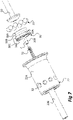
Fig. 7 is an exploded isometric view of certain components included in the brake actuator ofFigs 1-6 . - Referring to
Figs 1 and 2 , there is depicted a possible implementation of abrake actuator 1 in capacity of an actuator for a parking brake 3, which is adapted to act on abrake cylinder 2. Such a parking brake actuator may form part of a railway vehicle braking system. - The
brake actuator 1 and features thereof will now be generally described with reference toFig. 3 . Theactuator 1 comprises a housing orbody 20 having abase member 19 and acylindrical portion 25. Thebase member 19 has anopening 21 vis-à-vis thebrake cylinder 2. Theopening 21 is a circular opening slidingly receiving a thrust member in the shape of asleeve 22 fitting in theopening 21 in a sealed manner by virtue of sealing means 23, such as an O ring. - Furthermore, the
brake actuator 1 comprises apiston 24 mounted in thecylindrical portion 25 of thebody 20 and defining together with the body 20 apressure chamber 26 depicted inFig. 4 . Thepressure chamber 26 is supplied with pressurized fluid through a conduit 13 (seeFig. 1 ). Thepiston 24 is movable between a loaded position in which resilient means in the form ofsprings 29 are compressed, and actuated positions in which thesprings 29 are at least partially released in relation to the charged position. Sealing between thepiston 24 and thecylinder 25 is provided by aseal 27. - The
piston 24 comprises at its center an annular space ororifice 17 through which thethrust sleeve 22 translates. In particular, as shown inFig. 3 , thethrust sleeve 22 comprises acylindrical portion 22A and ahollow shaft portion 22B having a diameter substantially smaller than the diameter of thecylindrical portion 22A. Thecylindrical portion 22A is slidingly received in theorifice 17 of thepiston 24 and thehollow shaft portion 22B is slidingly received in theopening 21 of thebase member 19. Resilient means, formed in the present example by thesprings 29, continuously urge thepiston 24 towards its actuated position. - A
slide 30 is further disposed within thethrust sleeve 22 and adapted to translate axially between a locking position and a release position as will be further explained herein. In the schematic view ofFig. 3 , theslide 30 is in the release position and thepiston 24 in a fully actuated position. - The
brake actuator 1 further comprises an anchoringmember 36 received in theannular orifice 17 of thepiston 24 and shaped to form an axialflush surface 18 with an axialinner surface 16 of thepiston 24. In addition, the anchoringmember 36 is received in thepiston 24 to form therewith atransverse surface 14 which may be substantially flush and face thepressure chamber 26. In this sense, thetransverse surface 14 is a pneumatic surface on which pressurized fluid of thepressure chamber 26 acts. The pressure in thepressure chamber 26 thus exerts pneumatic force directly to thepiston 24 and to the anchoringmember 36, i.e. thetransverse surface 14 - The
piston 24 envelopes thethrust sleeve 22 as depicted inFig. 3 . The anchoringmember 36 comprises anannular portion 36A surrounding thethrust sleeve 22 and having an inner diameter corresponding to the outer diameter of thecylindrical portion 22A of thethrust sleeve 22 allowing the latter to translate therein. Theannular portion 36A of the anchoringmember 36 has an upperopen end portion 36B and a lowerbottom end 36C which is substantially closed and provided with a centrally arrangedorifice 36D which slidingly receives thehollow shaft portion 22B of thethrust sleeve 22, allowing it to translate there through. Thebottom end portion 36C may be disc-shaped, as depicted inFig. 3 , and provided with the centrally arrangedorifice 36D. - A dimensional ratio between the outer diameter of
hollow shaft portion 22B of thethrust sleeve 22 and the inner diameter of thecylinder 25 may be in the range of 0,08 - 0,15; preferably less than 0,1. In an exemplary embodiment the dimensional ratio is about 0,09. - The selected dimensional ratio facilitates that at a provided preparation pressure in
pressure chamber 26 and a provided installation dimension i.e. a limiting parameter to the diameter ofcylindrical portion 25. The present design enables increased actuation force in that relatively larger spring forces can be accommodated using the same installation dimension. - Accordingly, the
brake actuator 1 described herein achieves an improved actuation force per mounting/installation dimension. Thus, available installation dimension may be utilized more efficiently in that the actuator can be provided with a more compact design. - Sealing between the
thrust sleeve 22 and thebottom end portion 36C of the anchoringelement 36 is provided by aseal 28. - The
brake actuator 1 comprises a plurality ofballs 33, in the described example tenballs 33, disposed in respectivecircular opening 32 of thethrust sleeve 22 between theslide 30 and the anchoringmember 36 and/orpiston 24. Theopenings 32 are spaced and evenly distributed around the perimeter of thethrust sleeve 22 and extend transversely to its longitudinal axis. - The
balls 33 have a diameter matching the diameter of theopenings 32 and a cross section adapted to occupy a radially outwards projecting position in relation to thethrust sleeve 22 corresponding to the locking position of theslide 30 and a retracted position in relation to thesleeve 22 corresponding to the release position of theslide 30. - When the
slide 30 is in the locking position, the anchoringmember 36 is adapted to axially drive thethrust sleeve 22 through engagement with theballs 33, as shown inFigs 4 and5 . Conversely, when theslide 30 is in release position, the anchoringmember 36 is axially uncoupled from thethrust sleeve 22. This is shown inFigs 3 and6 . - The
balls 33 are caused to move radially outwards to adopt the projecting position under the action of alateral surface 38A-D of theslide 30. - The
slide 30 is permanently biased towards its locking position by resilient means in the shape of aspring 31 disposed between theslide 30 and thethrust sleeve 22. In particular, thespring 31 is disposed in thehollow shaft portion 22B of thethrust sleeve 22, in which theslide 30 is received. - As shown in
Fig. 3 , theslide 30 comprises ahead portion 30A and atail portion 30B in the shape of a push rod as depicted in the detail view ofFig. 7 . Thetail portion 30B is received in thehollow shaft portion 22B of thethrust sleeve 22 as shown inFig. 3 . - With reference to
Fig. 7 , theslide 30 is rotation symmetric about a center axis C thereof. In particular, thehead portion 30A is rotation symmetric. Thehead portion 30A comprises a chamfered profile surface 38. In particular, thehead portion 30A is chamfered to comprise a sequence of circumferentially and continuously extendinggrooves head portion 30A opposite thetail portion 30B, form a sequence ofgrooves slide 30 is provided with a laterally extending profile surface 38 of progressively increasing radius in the axial direction of theslide 30 towards thetail portion 30B. Thus, each transverse cross-section of theslide 30 has a constant radius. - The
slide 30 comprises two cylindrical portions providing anarrow release groove 38A and an expandedlocking groove 38C. A curvedtransitional groove 38B extends between therelease groove 38A and the expandedlocking groove 38C. Aheel groove 38D with a diameter greater than the lockinggroove 38C provides theslide 30 with a stop for retaining theballs 33 on thelock groove 38C in the axial direction. - The
transitional groove 38B comprises a circle arc shaped profile portion which may have a radius similar to that of theballs 33. Hereby theballs 33 are in contact with the surface of therelease groove 38B on a circle arc shaped line in the respective balls transition from therelease groove 38A to the lockinggroove 38C or vice versa. - When the
slide 30 translates from the release position to the locking position, therespective grooves 38A-38D of the profiled slide surface 38 engages with theballs 33 to cause theballs 33 to move radially outwards and to adopt a locking position wherein theballs 33 engage with the anchoringmember 36. - The number of
balls 33 may be selected depending on a number of parameters including, but not limited to, the restraining force ofspring 29. The number ofballs 33 may be in the range of three to sixteen. In the example described herein the number ofballs 33 is ten. - The anchoring
member 36 comprises a circumferentially extending local depression in the shape of aninner recess 15 for receiving theballs 33 in their respective release position, which corresponds to the projecting position in relation to thethrust sleeve 22. Therecess 15 protrudes radially outwards into theflush wall 18 and a cross section thereof may comprise two opposing bevels providing an upper boundary and a lower boundary respectively, having a lateral surface formed there between. The bevels may be linear. - The
brake actuator 1 also comprises arelease device 50 which is adapted to push theslide 30 into thethrust sleeve 22 by compressing thespring 31. Therelease device 50 is therefore adapted to cause theslide 30 to translate from its locking position to its release position as shown inFig. 6 . - The operation of the
brake actuator 1 in capacity of a parking brake will now be explained with reference to the Figures. - In
Fig. 4 , thebrake actuator 1 is in the charged or loaded state. A pressurized fluid circuit (not shown) typically pressurizes thepressure chamber 26 via the conduit 13 (seeFig. 1 ) and maintains thepiston 24 in its high charged position by exerting pneumatic pressure on thepiston 24 and the anchoringmember 36 which axially acts on thepiston 24, thereby forcing thepiston 24 to compress thesprings 29. - In the position shown in
Fig. 4 , theslide 30 is in its locking position by virtue of the biasing of thespring 31. In this position, the anchoringmember 36 and thethrust sleeve 22 are axially coupled/engaged through therecess 15 coupled to thethrust sleeve 22 by engaging with theballs 33. As shown, theballs 33 are situated in the explained projecting position relative to thethrust sleeve 22. - Each
ball 33 rests on the perimeter of therespective opening 32 and is trapped laterally between therecess 15 of the anchoringmember 36 and the lockinggroove 38C. - The
balls 33 are placed on a circle when arranged in their respective locking position and when arranged in their respective release position. This circle is disposed in a transverse plane of thebrake actuator 1 and coaxially with the center axis CA thereof (seeFig. 4 ). As understood fromFigs 4 and7 , the axes CA and C coincide on a common axis. - The diameter of the circle expands symmetrically in a uniform manner as the
balls 33 simultaneously move from their respective release positions towards their respective locking positions, and the diameter of the circle decreases symmetrically in a uniform manner as theballs 33 simultaneously move from their respective lock positions towards their respective release positions. - When the
balls 33 are in locking position, therecess 15 coincides with theopenings 32 and thelock groove 38C. When theballs 33 are in release position, thehead 30A of theslide 30 rests on or substantially abuts the bottom end portion of theannular portion 22A of thethrust sleeve 22, and theopenings 32 coincide with therelease groove 38A. - The center axes of
openings 32 in thethrust sleeve 22 are symmetrically arranged in a transverse plane of thebrake actuator 1. - The
recess 15 is formed in theanchor member 36 in such manner that when theannular portion 22A of thethrust sleeve 22 rests on or abuts the disc shape of the lower anchormember end portion 36C, therecess 15 coincides with theopenings 32 of thethrust sleeve 22. - Furthermore, the
recess 15 is formed in theanchor member 36 in such way that when thepiston 24 is in its charged position and thethrust sleeve 22 also is in its charged position, therecess 15 coincides with theopenings 32 of thethrust sleeve 22. - From the position of
Fig. 4 , a pressure drop in thepressure chamber 26 causes the spring force ofsprings 29 to overcome the resulting pneumatic force exerted collectively onpiston 24 and anchoringmember 36. Hereby thepiston 24 is pushed towards an actuated position with the effect of driving or biasing the anchoringmember 36 and thethrust sleeve 22. Since theballs 33 are in projecting position, the anchoringmember 36 thus drivingly engages theballs 33 in its axial movement, whereby theballs 33 drivingly engage thethrust sleeve 22. Thehollow shaft portion 22B of thethrust sleeve 22 is thus caused to translate axially through theopening 21 in thebase member 19, thus protruding from thebody 20 to provide braking force to thebrake cylinder 2 as shown inFigs 4 and5 . - The braking force of the
actuator 1 may be suspended by pressurizingpressure chamber 26 to overcome the spring force of thesprings 29. - Alternatively, the braking force of the
actuator 1 may be suspended by means of arelease device 50. - The engagement of the
release device 50 causes theslide 30 to adopt a release position, whereby theballs 33 move over theprofile slide 30, thus approaching the axis C of theslide 30 to be arranged to abut therelease groove 38A corresponding to a release position of theballs 33 as depicted inFig. 6 . - While the
balls 33 occupy their retracted position, the anchoringmember 36 is axially uncoupled from thethrust sleeve 22 whereby thethrust sleeve 22 translates axially in respect of the anchoringmember 36 under a counter force exerted by thebrake cylinder 2.
Claims (15)
- A brake actuator for a brake cylinder (2) of a railway vehicle brake system, said brake actuator (1) comprising:a thrust sleeve (22) configured to provide braking force to said brake system;a slide (30) mounted in said thrust sleeve (22) and movable axially between a release position and a locking position;a piston (24) biased by resilient means (29) and linked to an anchoring member (36); anda plurality of balls (33) disposed in respective openings (32) of said sleeve (22) between the slide (30) and the anchoring member (36);wherein said balls (33) in said locking position are configured to move under action of a profiled surface (38) of the slide (30) to adopt a projecting position in relation to said sleeve (22) to axially couple the anchoring member (36) with the sleeve (22);wherein said balls (33) in said release position are configured to adopt a retracted position in relation to said sleeve (22) to axially uncouple the anchoring member (36) from the sleeve (22);wherein said profiled surface (38) of the slide (30) comprises a locking groove (38C) configured to engagingly receive said balls (33) when the slide (30) is in said locking position; andwherein said locking groove (38C) is circumferentially oriented and extends continuously along a circumference of said slide (30).
- The brake actuator according to claim 1, wherein said profiled slide surface (38) comprises a release groove (38A) configured to engagingly receive said balls (33) when the slide (30) is in said release position; and wherein said release groove (38A) is circumferentially oriented and extends continuously along a circumference of said slide (30).
- The brake actuator according to claim 2, wherein said release groove (38A) and/or said locking groove (38C) each comprises cylindrical portions extending parallel to a center axis (C) of said slide (30).
- The brake actuator according to any one of the preceding claims, wherein said anchoring member (36) comprises an annular portion (36A) with an open end portion (36B) configured to receive said sleeve (22) and a bottom end portion (36C) provided with a centrally arranged orifice (36D) having a diameter substantially smaller than the diameter of said open end portion (36B).
- The brake actuator according to any one of the preceding claims, wherein said thrust sleeve (22) comprises a cylindrical portion (22A) and a hollow shaft portion (22B) having a diameter substantially smaller than the diameter of said cylindrical portion (22A).
- The brake actuator according to claim 5, wherein said hollow shaft portion (22B) is configured to protrude through said centrally arranged orifice (36D).
- The brake actuator according to claim 5 or 6, wherein said hollow shaft portion (22B) envelopes and houses a resilient member (31) acting on said slide (30).
- The brake actuator according to any one of claims 4 to 6, wherein said slide (30) comprises a head portion (30A) received in said annular portion (36A), and a tail portion (30B) which has a substantially smaller diameter and which is received in said hollow shaft portion (22B).
- The brake actuator according to any one of the preceding claims, wherein said anchoring member (36) is received in said piston (24) to form a flush lateral surface (18) and/or a transverse surface (14) therewith.
- The brake actuator according to any one of the preceding claims, wherein said anchoring member (36) comprises a circumferentially extending recess (15) configured to receive and engage said balls (33) in said locking position.
- The brake actuator according to any one of the preceding claims, wherein said slide (30) comprises a transition groove (38B) which extends from said release groove (38A) to said locking groove (38C) and which has a curved portion; and wherein said transition groove (38B) is circumferentially oriented and extends continuously along a circumference of said slide (30).
- The brake actuator according to any one of preceding claims, further comprising a release device (50) configured to drive said slide (30) from its locking position to its release position.
- A brake actuator for a brake cylinder (2) of a railway vehicle brake system, said brake actuator (1) comprising:a thrust sleeve (22) configured to provide braking force to said brake system;a slide (30) mounted in said thrust sleeve (22) and movable axially between a release position and a locking position;a piston (24) biased by resilient means (29) and linked to an anchoring part (36); anda plurality of balls (33) disposed in respective openings (32) of said sleeve (22) between the slide (30) and the anchoring member (36);wherein said balls (33) in said locking position are configured to move under action of a profiled surface (38) of the slide (30) to adopt a projecting position in relation to said sleeve (22) to axially couple the anchoring member (36) with the sleeve (22);wherein said balls (33) in said release position are configured to adopt a retracted position in relation to said sleeve (22) to axially uncouple the anchoring member (36) from the sleeve (22); andwherein said anchoring member (36) comprises an annular portion (36A) with an open end portion (36B) receiving said sleeve (22), and a bottom end portion (36C) provided with a centrally arranged orifice (36D).
- The brake actuator according to claim 13, wherein said thrust sleeve (22) comprises a cylindrical portion (22A) and a hollow shaft portion (22B) having a diameter substantially smaller than the diameter of said cylindrical portion (22A); and wherein said hollow shaft portion (22B) is received in said centrally arranged orifice (36D).
- A railway vehicle brake system, comprising a brake actuator as claimed in any one of the preceding claims.
Priority Applications (1)
| Application Number | Priority Date | Filing Date | Title |
|---|---|---|---|
| PL19711528T PL3762268T3 (en) | 2018-03-09 | 2019-03-08 | Brake actuator |
Applications Claiming Priority (2)
| Application Number | Priority Date | Filing Date | Title |
|---|---|---|---|
| SE1850263 | 2018-03-09 | ||
| PCT/EP2019/055893 WO2019170882A1 (en) | 2018-03-09 | 2019-03-08 | Brake actuator |
Publications (2)
| Publication Number | Publication Date |
|---|---|
| EP3762268A1 EP3762268A1 (en) | 2021-01-13 |
| EP3762268B1 true EP3762268B1 (en) | 2022-04-20 |
Family
ID=65812275
Family Applications (1)
| Application Number | Title | Priority Date | Filing Date |
|---|---|---|---|
| EP19711528.0A Active EP3762268B1 (en) | 2018-03-09 | 2019-03-08 | Brake actuator |
Country Status (7)
| Country | Link |
|---|---|
| US (1) | US11866017B2 (en) |
| EP (1) | EP3762268B1 (en) |
| CN (1) | CN111788095B (en) |
| ES (1) | ES2916049T3 (en) |
| HU (1) | HUE058784T2 (en) |
| PL (1) | PL3762268T3 (en) |
| WO (1) | WO2019170882A1 (en) |
Citations (1)
| Publication number | Priority date | Publication date | Assignee | Title |
|---|---|---|---|---|
| GB2109863A (en) * | 1979-03-06 | 1983-06-08 | Bendix Ltd | Spring force applying actuators |
Family Cites Families (12)
| Publication number | Priority date | Publication date | Assignee | Title |
|---|---|---|---|---|
| GB1192337A (en) * | 1968-11-05 | 1970-05-20 | Svenska Aktiebolaget Broms Reg | Improvements in Vehicle Brake-actuating Devices |
| DE2359967C3 (en) * | 1973-12-01 | 1979-05-10 | Knorr-Bremse Gmbh, 8000 Muenchen | Mechanical release device for spring brake cylinders |
| US4080875A (en) * | 1975-07-24 | 1978-03-28 | Alexandr Ivanovich Repolovsky | Vehicle braking means |
| GB2045868B (en) * | 1979-03-06 | 1983-05-25 | Bendix Westinghouse Ltd | Spring force applying actuators |
| DE3101608A1 (en) | 1981-01-20 | 1982-08-19 | Knorr-Bremse GmbH, 8000 München | Mechanical release device for spring brake cylinders |
| EP0172926B1 (en) * | 1984-08-23 | 1988-07-13 | Square D Starkstrom GmbH | Operating adaptor for command or signaling devices, in particular emergency stop switch |
| SU1316881A1 (en) * | 1986-01-22 | 1987-06-15 | Гродненский завод автомобильных агрегатов | Brake chamber with spring-type energy accumulator |
| US4951552A (en) * | 1989-11-27 | 1990-08-28 | Fox Anton F | Locking cylinder |
| SE0700046L (en) | 2007-01-12 | 2008-04-01 | Faiveley Transport Nordic Ab | parking arrangements |
| FR2934981B1 (en) | 2008-08-13 | 2010-09-24 | Faiveley Transp Amiens | PARKING BRAKE OR EMERGENCY ACTUATOR FOR BALL UNLOCKING BRAKE |
| US20190084546A1 (en) * | 2017-09-19 | 2019-03-21 | Jiaxing Lupai Brake Co., Ltd. | Spring clutch or brake |
| EP3498550B1 (en) * | 2017-12-13 | 2021-02-17 | WABCO Europe BVBA | Spring portion of a spring brake actuator, spring brake actuator and vehicle having the same |
-
2019
- 2019-03-08 HU HUE19711528A patent/HUE058784T2/en unknown
- 2019-03-08 EP EP19711528.0A patent/EP3762268B1/en active Active
- 2019-03-08 PL PL19711528T patent/PL3762268T3/en unknown
- 2019-03-08 ES ES19711528T patent/ES2916049T3/en active Active
- 2019-03-08 CN CN201980014807.1A patent/CN111788095B/en active Active
- 2019-03-08 WO PCT/EP2019/055893 patent/WO2019170882A1/en active Application Filing
- 2019-03-08 US US16/975,573 patent/US11866017B2/en active Active
Patent Citations (1)
| Publication number | Priority date | Publication date | Assignee | Title |
|---|---|---|---|---|
| GB2109863A (en) * | 1979-03-06 | 1983-06-08 | Bendix Ltd | Spring force applying actuators |
Also Published As
| Publication number | Publication date |
|---|---|
| CN111788095A (en) | 2020-10-16 |
| US20200398807A1 (en) | 2020-12-24 |
| PL3762268T3 (en) | 2022-06-27 |
| WO2019170882A1 (en) | 2019-09-12 |
| US11866017B2 (en) | 2024-01-09 |
| ES2916049T3 (en) | 2022-06-28 |
| CN111788095B (en) | 2023-05-23 |
| EP3762268A1 (en) | 2021-01-13 |
| HUE058784T2 (en) | 2022-09-28 |
Similar Documents
| Publication | Publication Date | Title |
|---|---|---|
| EP2414206B1 (en) | Brake actuator | |
| US11098777B2 (en) | Oversized brake piston footing | |
| US4480531A (en) | Mechanical quick-release mechanism for spring-loaded brake cylinders | |
| CN109311465A (en) | Spring braking actuator with septum retainer | |
| CN108944892A (en) | The spring braking actuator of clamping screw bearing with connection platen and actuator pipes | |
| JP2011524505A (en) | Piston formed by multiple members for brake caliper of disc brake | |
| WO2004005099A1 (en) | Park lock activated by fluid | |
| EP3762268B1 (en) | Brake actuator | |
| EP3105469B1 (en) | Center bearing of adapter plate comprising rubber and rigid plastic members developed for spring brake actuators | |
| EP3498550B1 (en) | Spring portion of a spring brake actuator, spring brake actuator and vehicle having the same | |
| KR101289669B1 (en) | Piston type of brake actuator appling pressurization type internal dual valve | |
| EP0016566B1 (en) | Spring force applying actuators | |
| RU2638882C2 (en) | Brake chamber with spring energy accumulator | |
| CN107477111B (en) | Retaining pin with foot to hold spring in disc brake assembly reaction plate and operate stator disc during assembly | |
| CN112112912B (en) | Spring brake actuator and brake release mechanism for such a spring brake actuator | |
| EP0074734B1 (en) | Actuator for brakes or the like | |
| EP3083353B1 (en) | Brake cylinder | |
| US7555902B2 (en) | Tandem master cylinder with central valves | |
| US4549636A (en) | Disc brakes for vehicles | |
| CN113696861A (en) | Parking actuating mechanism for vehicle and vehicle comprising same | |
| SU1357287A1 (en) | Spring power for parking brake | |
| EP4071015A1 (en) | Pneumatic spring brake actuator | |
| EP0654387B1 (en) | Fluid pressure operable spring force actuators | |
| GB1423160A (en) | Vehicle wheel brake actuators | |
| EP0203729A1 (en) | Improvements in self-energising disc brakes |
Legal Events
| Date | Code | Title | Description |
|---|---|---|---|
| STAA | Information on the status of an ep patent application or granted ep patent |
Free format text: STATUS: UNKNOWN |
|
| STAA | Information on the status of an ep patent application or granted ep patent |
Free format text: STATUS: THE INTERNATIONAL PUBLICATION HAS BEEN MADE |
|
| PUAI | Public reference made under article 153(3) epc to a published international application that has entered the european phase |
Free format text: ORIGINAL CODE: 0009012 |
|
| STAA | Information on the status of an ep patent application or granted ep patent |
Free format text: STATUS: REQUEST FOR EXAMINATION WAS MADE |
|
| 17P | Request for examination filed |
Effective date: 20200828 |
|
| AK | Designated contracting states |
Kind code of ref document: A1 Designated state(s): AL AT BE BG CH CY CZ DE DK EE ES FI FR GB GR HR HU IE IS IT LI LT LU LV MC MK MT NL NO PL PT RO RS SE SI SK SM TR |
|
| AX | Request for extension of the european patent |
Extension state: BA ME |
|
| DAV | Request for validation of the european patent (deleted) | ||
| DAX | Request for extension of the european patent (deleted) | ||
| GRAP | Despatch of communication of intention to grant a patent |
Free format text: ORIGINAL CODE: EPIDOSNIGR1 |
|
| STAA | Information on the status of an ep patent application or granted ep patent |
Free format text: STATUS: GRANT OF PATENT IS INTENDED |
|
| INTG | Intention to grant announced |
Effective date: 20211019 |
|
| GRAS | Grant fee paid |
Free format text: ORIGINAL CODE: EPIDOSNIGR3 |
|
| GRAA | (expected) grant |
Free format text: ORIGINAL CODE: 0009210 |
|
| STAA | Information on the status of an ep patent application or granted ep patent |
Free format text: STATUS: THE PATENT HAS BEEN GRANTED |
|
| AK | Designated contracting states |
Kind code of ref document: B1 Designated state(s): AL AT BE BG CH CY CZ DE DK EE ES FI FR GB GR HR HU IE IS IT LI LT LU LV MC MK MT NL NO PL PT RO RS SE SI SK SM TR |
|
| REG | Reference to a national code |
Ref country code: GB Ref legal event code: FG4D |
|
| REG | Reference to a national code |
Ref country code: CH Ref legal event code: EP |
|
| REG | Reference to a national code |
Ref country code: DE Ref legal event code: R096 Ref document number: 602019013902 Country of ref document: DE |
|
| REG | Reference to a national code |
Ref country code: IE Ref legal event code: FG4D |
|
| REG | Reference to a national code |
Ref country code: AT Ref legal event code: REF Ref document number: 1484948 Country of ref document: AT Kind code of ref document: T Effective date: 20220515 |
|
| REG | Reference to a national code |
Ref country code: SE Ref legal event code: TRGR |
|
| REG | Reference to a national code |
Ref country code: FI Ref legal event code: FGE |
|
| REG | Reference to a national code |
Ref country code: RO Ref legal event code: EPE |
|
| REG | Reference to a national code |
Ref country code: ES Ref legal event code: FG2A Ref document number: 2916049 Country of ref document: ES Kind code of ref document: T3 Effective date: 20220628 |
|
| REG | Reference to a national code |
Ref country code: LT Ref legal event code: MG9D |
|
| REG | Reference to a national code |
Ref country code: NL Ref legal event code: MP Effective date: 20220420 |
|
| REG | Reference to a national code |
Ref country code: AT Ref legal event code: MK05 Ref document number: 1484948 Country of ref document: AT Kind code of ref document: T Effective date: 20220420 |
|
| REG | Reference to a national code |
Ref country code: HU Ref legal event code: AG4A Ref document number: E058784 Country of ref document: HU |
|
| PG25 | Lapsed in a contracting state [announced via postgrant information from national office to epo] |
Ref country code: NL Free format text: LAPSE BECAUSE OF FAILURE TO SUBMIT A TRANSLATION OF THE DESCRIPTION OR TO PAY THE FEE WITHIN THE PRESCRIBED TIME-LIMIT Effective date: 20220420 |
|
| PG25 | Lapsed in a contracting state [announced via postgrant information from national office to epo] |
Ref country code: PT Free format text: LAPSE BECAUSE OF FAILURE TO SUBMIT A TRANSLATION OF THE DESCRIPTION OR TO PAY THE FEE WITHIN THE PRESCRIBED TIME-LIMIT Effective date: 20220822 Ref country code: NO Free format text: LAPSE BECAUSE OF FAILURE TO SUBMIT A TRANSLATION OF THE DESCRIPTION OR TO PAY THE FEE WITHIN THE PRESCRIBED TIME-LIMIT Effective date: 20220720 Ref country code: LT Free format text: LAPSE BECAUSE OF FAILURE TO SUBMIT A TRANSLATION OF THE DESCRIPTION OR TO PAY THE FEE WITHIN THE PRESCRIBED TIME-LIMIT Effective date: 20220420 Ref country code: HR Free format text: LAPSE BECAUSE OF FAILURE TO SUBMIT A TRANSLATION OF THE DESCRIPTION OR TO PAY THE FEE WITHIN THE PRESCRIBED TIME-LIMIT Effective date: 20220420 Ref country code: GR Free format text: LAPSE BECAUSE OF FAILURE TO SUBMIT A TRANSLATION OF THE DESCRIPTION OR TO PAY THE FEE WITHIN THE PRESCRIBED TIME-LIMIT Effective date: 20220721 Ref country code: BG Free format text: LAPSE BECAUSE OF FAILURE TO SUBMIT A TRANSLATION OF THE DESCRIPTION OR TO PAY THE FEE WITHIN THE PRESCRIBED TIME-LIMIT Effective date: 20220720 Ref country code: AT Free format text: LAPSE BECAUSE OF FAILURE TO SUBMIT A TRANSLATION OF THE DESCRIPTION OR TO PAY THE FEE WITHIN THE PRESCRIBED TIME-LIMIT Effective date: 20220420 |
|
| PG25 | Lapsed in a contracting state [announced via postgrant information from national office to epo] |
Ref country code: RS Free format text: LAPSE BECAUSE OF FAILURE TO SUBMIT A TRANSLATION OF THE DESCRIPTION OR TO PAY THE FEE WITHIN THE PRESCRIBED TIME-LIMIT Effective date: 20220420 Ref country code: LV Free format text: LAPSE BECAUSE OF FAILURE TO SUBMIT A TRANSLATION OF THE DESCRIPTION OR TO PAY THE FEE WITHIN THE PRESCRIBED TIME-LIMIT Effective date: 20220420 Ref country code: IS Free format text: LAPSE BECAUSE OF FAILURE TO SUBMIT A TRANSLATION OF THE DESCRIPTION OR TO PAY THE FEE WITHIN THE PRESCRIBED TIME-LIMIT Effective date: 20220820 |
|
| REG | Reference to a national code |
Ref country code: DE Ref legal event code: R097 Ref document number: 602019013902 Country of ref document: DE |
|
| PG25 | Lapsed in a contracting state [announced via postgrant information from national office to epo] |
Ref country code: SM Free format text: LAPSE BECAUSE OF FAILURE TO SUBMIT A TRANSLATION OF THE DESCRIPTION OR TO PAY THE FEE WITHIN THE PRESCRIBED TIME-LIMIT Effective date: 20220420 Ref country code: EE Free format text: LAPSE BECAUSE OF FAILURE TO SUBMIT A TRANSLATION OF THE DESCRIPTION OR TO PAY THE FEE WITHIN THE PRESCRIBED TIME-LIMIT Effective date: 20220420 Ref country code: DK Free format text: LAPSE BECAUSE OF FAILURE TO SUBMIT A TRANSLATION OF THE DESCRIPTION OR TO PAY THE FEE WITHIN THE PRESCRIBED TIME-LIMIT Effective date: 20220420 |
|
| PLBE | No opposition filed within time limit |
Free format text: ORIGINAL CODE: 0009261 |
|
| STAA | Information on the status of an ep patent application or granted ep patent |
Free format text: STATUS: NO OPPOSITION FILED WITHIN TIME LIMIT |
|
| 26N | No opposition filed |
Effective date: 20230123 |
|
| PG25 | Lapsed in a contracting state [announced via postgrant information from national office to epo] |
Ref country code: AL Free format text: LAPSE BECAUSE OF FAILURE TO SUBMIT A TRANSLATION OF THE DESCRIPTION OR TO PAY THE FEE WITHIN THE PRESCRIBED TIME-LIMIT Effective date: 20220420 |
|
| PGFP | Annual fee paid to national office [announced via postgrant information from national office to epo] |
Ref country code: RO Payment date: 20230308 Year of fee payment: 5 Ref country code: FR Payment date: 20230321 Year of fee payment: 5 Ref country code: FI Payment date: 20230327 Year of fee payment: 5 Ref country code: CZ Payment date: 20230224 Year of fee payment: 5 |
|
| PG25 | Lapsed in a contracting state [announced via postgrant information from national office to epo] |
Ref country code: SI Free format text: LAPSE BECAUSE OF FAILURE TO SUBMIT A TRANSLATION OF THE DESCRIPTION OR TO PAY THE FEE WITHIN THE PRESCRIBED TIME-LIMIT Effective date: 20220420 |
|
| PGFP | Annual fee paid to national office [announced via postgrant information from national office to epo] |
Ref country code: SK Payment date: 20230223 Year of fee payment: 5 Ref country code: SE Payment date: 20230329 Year of fee payment: 5 Ref country code: PL Payment date: 20230227 Year of fee payment: 5 Ref country code: IT Payment date: 20230329 Year of fee payment: 5 Ref country code: HU Payment date: 20230222 Year of fee payment: 5 Ref country code: GB Payment date: 20230316 Year of fee payment: 5 Ref country code: DE Payment date: 20230316 Year of fee payment: 5 |
|
| P01 | Opt-out of the competence of the unified patent court (upc) registered |
Effective date: 20230530 |
|
| PGFP | Annual fee paid to national office [announced via postgrant information from national office to epo] |
Ref country code: ES Payment date: 20230411 Year of fee payment: 5 |
|
| PG25 | Lapsed in a contracting state [announced via postgrant information from national office to epo] |
Ref country code: MC Free format text: LAPSE BECAUSE OF FAILURE TO SUBMIT A TRANSLATION OF THE DESCRIPTION OR TO PAY THE FEE WITHIN THE PRESCRIBED TIME-LIMIT Effective date: 20220420 |
|
| REG | Reference to a national code |
Ref country code: CH Ref legal event code: PL |
|
| REG | Reference to a national code |
Ref country code: BE Ref legal event code: MM Effective date: 20230331 |
|
| PG25 | Lapsed in a contracting state [announced via postgrant information from national office to epo] |
Ref country code: LU Free format text: LAPSE BECAUSE OF NON-PAYMENT OF DUE FEES Effective date: 20230308 |
|
| REG | Reference to a national code |
Ref country code: IE Ref legal event code: MM4A |
|
| PG25 | Lapsed in a contracting state [announced via postgrant information from national office to epo] |
Ref country code: LI Free format text: LAPSE BECAUSE OF NON-PAYMENT OF DUE FEES Effective date: 20230331 Ref country code: IE Free format text: LAPSE BECAUSE OF NON-PAYMENT OF DUE FEES Effective date: 20230308 Ref country code: CH Free format text: LAPSE BECAUSE OF NON-PAYMENT OF DUE FEES Effective date: 20230331 |
|
| PG25 | Lapsed in a contracting state [announced via postgrant information from national office to epo] |
Ref country code: BE Free format text: LAPSE BECAUSE OF NON-PAYMENT OF DUE FEES Effective date: 20230331 |