EP3762263B1 - Befestigungshalterung für eine elektronische einheit zur montage im seitenteil eines kraftfahrzeugkofferraums - Google Patents
Befestigungshalterung für eine elektronische einheit zur montage im seitenteil eines kraftfahrzeugkofferraums Download PDFInfo
- Publication number
- EP3762263B1 EP3762263B1 EP19759636.4A EP19759636A EP3762263B1 EP 3762263 B1 EP3762263 B1 EP 3762263B1 EP 19759636 A EP19759636 A EP 19759636A EP 3762263 B1 EP3762263 B1 EP 3762263B1
- Authority
- EP
- European Patent Office
- Prior art keywords
- plate
- support
- bracket
- extending
- fixing
- Prior art date
- Legal status (The legal status is an assumption and is not a legal conclusion. Google has not performed a legal analysis and makes no representation as to the accuracy of the status listed.)
- Active
Links
- BASFCYQUMIYNBI-UHFFFAOYSA-N platinum Chemical compound [Pt] BASFCYQUMIYNBI-UHFFFAOYSA-N 0.000 claims description 12
- 229910052751 metal Inorganic materials 0.000 claims description 5
- 239000002184 metal Substances 0.000 claims description 5
- 230000014759 maintenance of location Effects 0.000 claims 1
- 229910052697 platinum Inorganic materials 0.000 claims 1
- 230000003014 reinforcing effect Effects 0.000 description 4
- 238000004873 anchoring Methods 0.000 description 3
- 238000009434 installation Methods 0.000 description 3
- 238000009423 ventilation Methods 0.000 description 3
- 238000005452 bending Methods 0.000 description 2
- 210000001364 upper extremity Anatomy 0.000 description 2
- 241001441732 Ostraciidae Species 0.000 description 1
- 229910000831 Steel Inorganic materials 0.000 description 1
- 229910052782 aluminium Inorganic materials 0.000 description 1
- XAGFODPZIPBFFR-UHFFFAOYSA-N aluminium Chemical compound [Al] XAGFODPZIPBFFR-UHFFFAOYSA-N 0.000 description 1
- 238000012550 audit Methods 0.000 description 1
- 230000000593 degrading effect Effects 0.000 description 1
- 238000009792 diffusion process Methods 0.000 description 1
- 230000000694 effects Effects 0.000 description 1
- 239000006260 foam Substances 0.000 description 1
- 230000003116 impacting effect Effects 0.000 description 1
- 238000002513 implantation Methods 0.000 description 1
- 238000009413 insulation Methods 0.000 description 1
- 239000000463 material Substances 0.000 description 1
- 238000000465 moulding Methods 0.000 description 1
- 238000013021 overheating Methods 0.000 description 1
- 239000004033 plastic Substances 0.000 description 1
- 230000002787 reinforcement Effects 0.000 description 1
- 230000000284 resting effect Effects 0.000 description 1
- 238000010079 rubber tapping Methods 0.000 description 1
- 238000012216 screening Methods 0.000 description 1
- 239000010959 steel Substances 0.000 description 1
- 229920002994 synthetic fiber Polymers 0.000 description 1
- 238000003856 thermoforming Methods 0.000 description 1
- 239000012815 thermoplastic material Substances 0.000 description 1
- 230000000007 visual effect Effects 0.000 description 1
- 238000003466 welding Methods 0.000 description 1
Images

Classifications
-
- B—PERFORMING OPERATIONS; TRANSPORTING
- B60—VEHICLES IN GENERAL
- B60R—VEHICLES, VEHICLE FITTINGS, OR VEHICLE PARTS, NOT OTHERWISE PROVIDED FOR
- B60R16/00—Electric or fluid circuits specially adapted for vehicles and not otherwise provided for; Arrangement of elements of electric or fluid circuits specially adapted for vehicles and not otherwise provided for
- B60R16/02—Electric or fluid circuits specially adapted for vehicles and not otherwise provided for; Arrangement of elements of electric or fluid circuits specially adapted for vehicles and not otherwise provided for electric constitutive elements
- B60R16/023—Electric or fluid circuits specially adapted for vehicles and not otherwise provided for; Arrangement of elements of electric or fluid circuits specially adapted for vehicles and not otherwise provided for electric constitutive elements for transmission of signals between vehicle parts or subsystems
- B60R16/0239—Electronic boxes
-
- B—PERFORMING OPERATIONS; TRANSPORTING
- B60—VEHICLES IN GENERAL
- B60R—VEHICLES, VEHICLE FITTINGS, OR VEHICLE PARTS, NOT OTHERWISE PROVIDED FOR
- B60R11/00—Arrangements for holding or mounting articles, not otherwise provided for
- B60R11/02—Arrangements for holding or mounting articles, not otherwise provided for for radio sets, television sets, telephones, or the like; Arrangement of controls thereof
- B60R11/0264—Arrangements for holding or mounting articles, not otherwise provided for for radio sets, television sets, telephones, or the like; Arrangement of controls thereof for control means
-
- B—PERFORMING OPERATIONS; TRANSPORTING
- B60—VEHICLES IN GENERAL
- B60R—VEHICLES, VEHICLE FITTINGS, OR VEHICLE PARTS, NOT OTHERWISE PROVIDED FOR
- B60R16/00—Electric or fluid circuits specially adapted for vehicles and not otherwise provided for; Arrangement of elements of electric or fluid circuits specially adapted for vehicles and not otherwise provided for
- B60R16/02—Electric or fluid circuits specially adapted for vehicles and not otherwise provided for; Arrangement of elements of electric or fluid circuits specially adapted for vehicles and not otherwise provided for electric constitutive elements
- B60R16/0207—Wire harnesses
- B60R16/0215—Protecting, fastening and routing means therefor
-
- B—PERFORMING OPERATIONS; TRANSPORTING
- B60—VEHICLES IN GENERAL
- B60R—VEHICLES, VEHICLE FITTINGS, OR VEHICLE PARTS, NOT OTHERWISE PROVIDED FOR
- B60R11/00—Arrangements for holding or mounting articles, not otherwise provided for
- B60R2011/0001—Arrangements for holding or mounting articles, not otherwise provided for characterised by position
- B60R2011/0003—Arrangements for holding or mounting articles, not otherwise provided for characterised by position inside the vehicle
- B60R2011/0036—Luggage compartment
Definitions
- the present invention generally relates to the problem of installing an electronic unit in the trunk of a motor vehicle.
- It relates in particular to a mounting bracket for such an electronic unit.
- the power of the amplifier integrated in the car radio (or in the sound diffusion module when the vehicle is fitted with a more advanced infotainment device) is insufficient to optimally supply the loudspeakers. speakers that require a certain voltage to be excited.
- such an amplifier is generally installed in the boot of the vehicle against a side trim trim, being fixed directly to the side flank of the body structure using self-tapping screws or via a fixing support as described for example in the European application EP 3 246 579 A1 .
- the document WO2016/001532 shows a mounting bracket for an electronic box according to the preamble of claim 1 and describes an assembly comprising a bracket comprising a central part on which an electronic box is fixed, a first end fixed to the body of a vehicle and a second end, opposite the first end with respect to the central part, comprising means for fixing a heat shield making it possible to maintain the heat shield at a distance from the electronic box.
- some car manufacturers offer optional audio kits on certain vehicle models fitted with an amplifier inserted between a side trim of the trunk and a lateral side of the body structure to which it is fixed.
- the side trim When such an amplifier is present, the side trim must be set back a sufficient distance from this amplifier to obtain a ventilation space capable of evacuating the heat generated by the latter and preventing this trim not be subjected to excessively high temperatures which could damage it.
- this spacing is greatly oversized, which leads to a significant reduction useful storage volume.
- the present invention therefore aims to optimize the loading volume of the trunk while guaranteeing sufficient ventilation for the amplifier.
- the retaining arms of the fixing support according to the invention make it possible to permanently maintain the side trim at a predetermined distance from the electronic box (consisting for example of an audio amplifier), and in particular when the latter is subjected during the phases cornering to lateral stresses exerted by the loads contained in the boot.
- the invention therefore avoids having to oversize in design the spacing of this covering trim vis-à-vis the corresponding side wall, which makes it possible to optimize the useful storage volume of the trunk.
- the invention also relates in a second aspect to an assembly comprising such a fixing support and a said electronic box mounted on said support by means of said fixing means.
- the curved free ends of said retaining arms protrude transversely from the external face of said casing by a predetermined distance advantageously comprised between 20 and 30 mm.
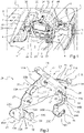
- the figure 1 represents a partial view of a motor vehicle trunk 1 delimited at the front by the backrests 2 of a row of rear seats, in the lower part by a floor 3, at the rear by a trunk panel or a tailgate not visible, in the upper part by screening means formed by a fixed or removable rear shelf, not shown, and on the sides by two lateral flanks of which only the right flank 4 is visible.
- the latter comprises a side wall 5 constituting part of the body structure of the vehicle and in which is formed a boss 5A forming the wheel arch.
- the side flank 4 also comprises at its front end two metallic reinforcing pieces in stamped sheet metal 6, 7 fixed one above the other to the side wall 5 (the lower reinforcing piece 6 being further fixed to the floor 3 ) and filling the recess formed in this side wall 5 at the front of the boss 5A.
- this side wall 4 is covered by a semi-rigid side trim 9 made of plastic material or carpet, obtained for example by molding or thermoforming and whose geometry is defined by the constraints of the architecture of the vehicle and in particular by the shape of the side wall.
- the trunk 1 houses an electronic box consisting of an audio amplifier 10 inserted between the side trim 9 and the right side flank 4 as shown in this figure 4 ,
- this amplifier 10 is fixed against this right side wall 4 by means of a fixing support 20 according to the invention.
- the mounting bracket 20 comprises a metal plate 21 having an outer receiving face for the audio amplifier 10.
- This plate 21 comprises a triangular-shaped plate 22 extending along a vertical longitudinal plane and provided to receive the amplifier 10, two front 23 and upper 24 securing tabs making it possible to rigidly secure the support 20 respectively to the lower part of reinforcement 6 and to the upper portion of the boss 5A of the lateral side 4, and a lower anchoring lug 25 making it possible to rigidly secure this support 20 to the floor 3.
- the support 20 also comprises three threaded fixing studs 26 extending transversely projecting from the external face of the plate 21 and making it possible to rigidly secure the audio amplifier 10 to this plate 21.
- these three studs 26 are welded to the center of three circular bosses 27 produced by stamping on the triangular plate 22 close to its three vertices in order to facilitate the positioning of the head of a welding tool.
- the three studs 26 are provided to cooperate with three lugs 11 provided on the amplifier 10 and each provided with an orifice intended to be threaded onto a said corresponding stud to allow the fixing of this amplifier 10 on the support 20 at the using nuts that are screwed onto these studs 26.
- the front securing tab 23 comprises a proximal portion 23A extending downwards coplanarly with the wall 22, an intermediate portion inclined 23B extending from the outer side, as well as a distal portion 23C extending in front of the plate 22 and along a vertical longitudinal plane parallel to the latter.
- This distal portion 23C also has a circular attachment hole 23D intended to allow, as shown in the figure 1 , the fixing of the front leg 23 on the lower reinforcing part 6, using a screw passing through this orifice as well as a hole made in the reinforcing part 6 and being screwed onto a nut welded around this hole on the inside face of this part 6.
- the upper securing tab 24 inclined on the internal side has an oblong attachment notch 24A intended to allow, as shown in the figure 1 , its attachment to the top of the boss 5A of the side wall 5, using a nut which is screwed onto a threaded stud 12 welded to this boss 5A and previously inserted into this notch 24A.
- the lower anchoring tab 25 comprises a proximal portion 25A in the shape of a square extending downwards then upwards. front coplanar with the wall 22, an intermediate portion 25B extending downwards from the free end of the proximal portion 25A and in a plane substantially coplanar with the latter, as well as a curved distal portion 25C extending from the side external perpendicular to the intermediate portion 25B and along a horizontal plane.
- This curved distal portion 25C also has an oblong attachment orifice 25D intended to allow, as shown in the figure 1 , the fixing of the lower leg 25 on the floor 3, using a screw passing through this orifice 23D as well as a hole made in this floor 3 and being screwed onto a nut welded around this hole on the face bottom of this same floor 3.
- the plate 21 also includes three buttonholes 28 formed in its rear part and each intended, as illustrated in the figure 1 , to allow the fixing by snap-fastening of a respective clamping clip 13 of the various electrical supply harnesses 14 connected to the amplifier 10.
- buttonsholes 28 are arranged respectively on the plate 22 close to its lower rear vertex, at the free end of the square-shaped proximal portion 25A of the lower tab 25, and at the free end of a curved tab 29 connected to the distal portion 25C of this same lower tab 25.
- the support 20 finally comprises four L-section retaining arms 30, 31, 32, 33 each comprising an elongated main part 30A, 31A, 32A, 33A extending transversely projecting from the external face of the plate 21, as well as a curved free end 30B, 31B, 32B, 33B extending perpendicularly to this proximal branch and along a vertical longitudinal plane parallel to plate 22.
- the curved free ends 30B, 31B, 32B, 33B of the arms are designed to rest in abutment against a foam plate 9A provided on the internal face of the side trim 9 so as to retain it laterally.
- the length of the arms is also calculated so as to permanently maintain their curved free ends (and therefore the side trim 9 resting there) separated by a predetermined distance advantageously between 20 and 30 mm from the external face of the audio amplifier 10 fixed against plate 22 of plate 21.
- Such an audio amplifier conventionally having a thickness of about 50 mm, the length of the arms 30, 31, 32, 33 will therefore in practice be at least 70 mm and advantageously between 70 and 80 mm.
- the retaining arms 30, 31, 32, 33 and the plate 21 are made by bending and stamping from the same sheet of sheet metal (advantageously steel or aluminum) cut beforehand.
- the retaining arms 30, 31, 32, 33 advantageously have stamped stiffening ribs 34 at their fold lines.
- the two arms 30, 31 extend from the plate 22 symmetrically with respect to the median transverse plane of the latter. More specifically, the arm 30 takes root on the side edge 22A of this plate 22 connecting its front and upper vertices, while the arm 31 takes root on its lateral edge 22B connecting its rear vertices.
- the two arms 32, 33 extend from the two front 23 and lower 25 legs. More precisely, the arm 32 takes root on the rear edge of the proximal portion 23A of the front leg 23, while the arm 33 takes root on the front edge of the proximal angle-shaped portion 25A of the lower leg 25.
- the means for fixing the case to the plate and/or the means for securing the support to the lateral side of the body structure are different.
- the number and/or the shape of the retaining arms are also different.
- the plate and the retaining arms are molded in one piece from a thermoplastic material reinforced with natural and/or synthetic fibres.
Claims (9)
- Halterung für ein elektronisches Gehäuse (10) zur Befestigung im Seitenteil eines Kraftfahrzeugkofferraums (1) zwischen einer Seitenflanke (4) der Karosseriekonstruktion des Fahrzeugs und einer diesen überdeckenden Seitenverkleidung (9), wobei die Halterung umfasst:- eine Platine (21) mit einer äußeren Aufnahmeseite für das Gehäuse (10),- Befestigungsmittel (26) zur Befestigung des Gehäuses (10) an der Platine (21) und- Befestigungsmittel (23, 24) zur Befestigung des Trägers an der Seitenflanke (4);der Halter ferner mehrere Haltearme (30, 31, 32, 33) aufweist, die sich quer von der Außenseite der Platine (21) erstrecken und gekrümmte freie Enden (30B, 31B, 32B, 33B) aufweisen, die so ausgebildet sind, dass sie bei am Fahrzeug angebrachter Platine an der Innenseite der seitlichen Verkleidung (9) anliegen,
ledit support étant caractérisé en ce que lesdits moyens d'arrimage comportent une première patte (23) s'étendant à une première extrémité de ladite platine (21) et présentant un orifice d'attache circulaire (23D), ainsi qu'une deuxième patte (24) s'étendant à une deuxième extrémité de ladite platine (21) et présentant une encoche d'attache oblongue (24A). - Befestigungsträger nach Anspruch 1, dadurch gekennzeichnet, dass die Platine (21) und die Haltearme (30, 31, 32, 33) durch Biegen und Tiefziehen aus ein und derselben zuvor geschnittenen Blechfolie hergestellt sind.
- Befestigungsträger nach Anspruch 2, dadurch gekennzeichnet, dass die Haltearme (30, 31, 32, 33) an ihren Faltlinien tiefgezogene Versteifungsrippen (34) aufweisen.
- Befestigungshalterung nach einem der Ansprüche 1 bis 3, dadurch gekennzeichnet, dass die Befestigungsmittel eine Vielzahl von Gewindebolzen (26) umfassen, die sich quer von der Außenfläche der Platine (21) erstrecken.
- Befestigungsträger nach Anspruch 4, dadurch gekennzeichnet, dass die Platte (21) eine Verankerungslasche (25) aufweist, die sich an einem dritten ihrer Enden erstreckt und einen gekrümmten distalen Abschnitt (25C) aufweist, der mit einer Öffnung (25D) versehen ist, die es ermöglicht, den Träger mit dem Boden (3) des Fahrzeugs zu verbinden.
- Befestigungsträger nach einem der Ansprüche 1 bis 5, dadurch gekennzeichnet, dass die Platine (21) mindestens ein Langloch (28) aufweist, das vorgesehen ist, um die Befestigung einer Klemmklammer (13) eines elektrischen Versorgungsbündels (14), das an das Gehäuse (10) angeschlossen ist, durch Einrasten zu ermöglichen.
- Anordnung mit einem Befestigungsträger (20) nach einem der Ansprüche 1 bis 6 und einem elektronischen Gehäuse, das über die Befestigungsmittel (26) an dem Träger angebracht ist.
- Anordnung nach Anspruch 7, dadurch gekennzeichnet, dass die gebogenen freien Enden (30B, 31B, 32B, 33B) der Haltearme (30, 31, 32, 33) quer von der Außenfläche des Gehäuses (10) um einen vorbestimmten Abstand vorstehen.
- Anordnung nach Anspruch 8, dadurch gekennzeichnet, dass der vorbestimmte Abstand zwischen 20 und 30 mm liegt.
Applications Claiming Priority (2)
| Application Number | Priority Date | Filing Date | Title |
|---|---|---|---|
| FR1851850A FR3078513B1 (fr) | 2018-03-05 | 2018-03-05 | Support de fixation pour boitier electronique destine a etre monte dans la partie laterale d’un coffre de vehicule automobile. |
| PCT/FR2019/050241 WO2019170969A2 (fr) | 2018-03-05 | 2019-02-04 | Support de fixation pour boitier électronique destine à être monte dans la partie latérale d'un coffre de véhicule automobile |
Publications (2)
| Publication Number | Publication Date |
|---|---|
| EP3762263A2 EP3762263A2 (de) | 2021-01-13 |
| EP3762263B1 true EP3762263B1 (de) | 2022-03-30 |
Family
ID=61873623
Family Applications (1)
| Application Number | Title | Priority Date | Filing Date |
|---|---|---|---|
| EP19759636.4A Active EP3762263B1 (de) | 2018-03-05 | 2019-02-04 | Befestigungshalterung für eine elektronische einheit zur montage im seitenteil eines kraftfahrzeugkofferraums |
Country Status (3)
| Country | Link |
|---|---|
| EP (1) | EP3762263B1 (de) |
| FR (1) | FR3078513B1 (de) |
| WO (1) | WO2019170969A2 (de) |
Families Citing this family (5)
| Publication number | Priority date | Publication date | Assignee | Title |
|---|---|---|---|---|
| FR3111322B1 (fr) * | 2020-06-16 | 2022-09-09 | Psa Automobiles Sa | Support de calculateur embarqué de véhicule |
| FR3111598B1 (fr) * | 2020-06-23 | 2022-08-26 | Psa Automobiles Sa | Capot de support d’alarme |
| FR3117427A1 (fr) * | 2020-12-10 | 2022-06-17 | Psa Automobiles Sa | Ensemble pour vehicule automobile comprenant un support de fixation |
| FR3125988B1 (fr) * | 2021-08-04 | 2023-08-11 | Renault Sas | Dispositif de support pour un amplificateur et un calculateur |
| FR3135936A1 (fr) | 2022-05-30 | 2023-12-01 | Psa Automobiles Sa | Support de boîtier électronique pour vehicules automobiles |
Citations (1)
| Publication number | Priority date | Publication date | Assignee | Title |
|---|---|---|---|---|
| EP1093954B1 (de) * | 1999-10-19 | 2003-10-08 | Renault V.I. | Vorrichtung zur Montage eines elektronischen Rechners auf einem Motor eines Kraftfahrzeuges |
Family Cites Families (5)
| Publication number | Priority date | Publication date | Assignee | Title |
|---|---|---|---|---|
| DE10206503C1 (de) * | 2002-02-16 | 2003-08-14 | Daimler Chrysler Ag | Schwenkbare Halterung, insbesondere für elektrische bzw. elektronische Bauteile und -gruppen, in einem Kraftfahrzeug |
| FR2950600B1 (fr) * | 2009-09-29 | 2011-11-04 | Renault Sa | Agencement d'un calculateur de frein de parking automatique dans un tel vehicule automobile et vehicule automobile comportant un tel agencement |
| FR3023233B1 (fr) * | 2014-07-01 | 2016-07-15 | Peugeot Citroen Automobiles Sa | Support pour la fixation d'un boitier electronique et d'un ecran thermique |
| JP6485223B2 (ja) * | 2015-05-28 | 2019-03-20 | スズキ株式会社 | コントローラ取付構造 |
| FR3051519B1 (fr) * | 2016-05-20 | 2018-05-04 | Renault S.A.S | Element de fixation pour un boitier fonctionnel, notamment de vehicule automobile. |
-
2018
- 2018-03-05 FR FR1851850A patent/FR3078513B1/fr not_active Expired - Fee Related
-
2019
- 2019-02-04 WO PCT/FR2019/050241 patent/WO2019170969A2/fr unknown
- 2019-02-04 EP EP19759636.4A patent/EP3762263B1/de active Active
Patent Citations (1)
| Publication number | Priority date | Publication date | Assignee | Title |
|---|---|---|---|---|
| EP1093954B1 (de) * | 1999-10-19 | 2003-10-08 | Renault V.I. | Vorrichtung zur Montage eines elektronischen Rechners auf einem Motor eines Kraftfahrzeuges |
Also Published As
| Publication number | Publication date |
|---|---|
| FR3078513B1 (fr) | 2020-02-14 |
| EP3762263A2 (de) | 2021-01-13 |
| WO2019170969A2 (fr) | 2019-09-12 |
| FR3078513A1 (fr) | 2019-09-06 |
| WO2019170969A3 (fr) | 2019-11-07 |
Similar Documents
| Publication | Publication Date | Title |
|---|---|---|
| EP3762263B1 (de) | Befestigungshalterung für eine elektronische einheit zur montage im seitenteil eines kraftfahrzeugkofferraums | |
| EP1442926B1 (de) | Fahrzeugsitzüberzug mit einer tragbaren Videoanlage. | |
| EP3724039B1 (de) | Trennwand für ein kraftfahrzeug | |
| FR2851969A1 (fr) | Support de capteur d'un vehicule automobile | |
| EP2678194A1 (de) | Halterung für einen sicherheitsgurtaufroller | |
| EP1666309B1 (de) | Clip zur Befestigung einer Dachverkleidung eines Fahrzeuges, Einheiten aus solchen Clips und einer Dachverkleidung sowie damit ausgestattetes Fahrzeug | |
| FR2825964A1 (fr) | Face avant de vehicule automobile avec equipements integres | |
| EP2925565B1 (de) | Dachstruktur für ein kraftfahrzeug | |
| EP2483114B1 (de) | Automatische parkbremsen-computer-anordnung in einem kraftfahrzeug und kraftfahrzeug mit einer derartigen anordnung | |
| FR3083751A1 (fr) | Guide d'air en materiau polymere expanse equipe d'elements de maintien sur une traverse extreme avant | |
| EP4028273B1 (de) | Stromversorgungsanordnung für ein kraftfahrzeug | |
| WO2018215706A1 (fr) | Dispositif de maintien d'une couverture d'insonorisation de traverse inferieure de baie et de tablier avant | |
| EP1283124B1 (de) | Vorrichtung zur Befestigung eines Sitzes auf einem Fahrzeugboden | |
| WO2017103368A1 (fr) | Dispositif de garnissage à airbag intégré, pour un véhicule | |
| EP1584516A1 (de) | Einheit zum Montieren einer Dachreeling auf einem Fahrzeugdach | |
| EP3835136A1 (de) | Anordnung zum befestigen einer batterie an bord eines fahrzeugs, die einen befestigungsflansch mit einer indexierungs- und verwechslungssicherungslasche umfasst | |
| FR3079182A1 (fr) | Support de fixation etage pour boitiers electroniques destine a etre monte dans la partie laterale d’un coffre de vehicule automobile. | |
| FR2834250A1 (fr) | Structure rigide d'element de siege comprenant un support pour permettre l'accrochage d'un organe sur le siege | |
| EP1717106A1 (de) | Anordnung eines Elektonikgehäuseträgers in einem Kraftfahrzeug | |
| FR2885278A1 (fr) | Agencement d'une grille de haut-parleur | |
| FR2886602A1 (fr) | Systeme d'ancrage pour une ceinture de securite equipant un siege de place arriere, face route, d'un habitacle de vehicule camping-car type cellule ou fourgon | |
| EP3788661A1 (de) | Vorrichtung zum befestigen einer 12v-batterie an einem batteriehalter und kraftfahrzeug mit einer solchen vorrichtung | |
| FR3120578A1 (fr) | Support d’un chargeur de batterie électrique d’un véhicule automobile | |
| FR3106805A1 (fr) | Agencement de zone arrière de structure de caisse de véhicule dotée d’éléments de renfort latéraux | |
| FR3134359A1 (fr) | Patte de fixation d’un projecteur de véhicule automobile |
Legal Events
| Date | Code | Title | Description |
|---|---|---|---|
| STAA | Information on the status of an ep patent application or granted ep patent |
Free format text: STATUS: UNKNOWN |
|
| STAA | Information on the status of an ep patent application or granted ep patent |
Free format text: STATUS: THE INTERNATIONAL PUBLICATION HAS BEEN MADE |
|
| PUAI | Public reference made under article 153(3) epc to a published international application that has entered the european phase |
Free format text: ORIGINAL CODE: 0009012 |
|
| STAA | Information on the status of an ep patent application or granted ep patent |
Free format text: STATUS: REQUEST FOR EXAMINATION WAS MADE |
|
| 17P | Request for examination filed |
Effective date: 20200907 |
|
| AK | Designated contracting states |
Kind code of ref document: A2 Designated state(s): AL AT BE BG CH CY CZ DE DK EE ES FI FR GB GR HR HU IE IS IT LI LT LU LV MC MK MT NL NO PL PT RO RS SE SI SK SM TR |
|
| AX | Request for extension of the european patent |
Extension state: BA ME |
|
| DAV | Request for validation of the european patent (deleted) | ||
| DAX | Request for extension of the european patent (deleted) | ||
| GRAP | Despatch of communication of intention to grant a patent |
Free format text: ORIGINAL CODE: EPIDOSNIGR1 |
|
| STAA | Information on the status of an ep patent application or granted ep patent |
Free format text: STATUS: GRANT OF PATENT IS INTENDED |
|
| INTG | Intention to grant announced |
Effective date: 20211006 |
|
| GRAS | Grant fee paid |
Free format text: ORIGINAL CODE: EPIDOSNIGR3 |
|
| GRAA | (expected) grant |
Free format text: ORIGINAL CODE: 0009210 |
|
| STAA | Information on the status of an ep patent application or granted ep patent |
Free format text: STATUS: THE PATENT HAS BEEN GRANTED |
|
| AK | Designated contracting states |
Kind code of ref document: B1 Designated state(s): AL AT BE BG CH CY CZ DE DK EE ES FI FR GB GR HR HU IE IS IT LI LT LU LV MC MK MT NL NO PL PT RO RS SE SI SK SM TR |
|
| REG | Reference to a national code |
Ref country code: GB Ref legal event code: FG4D Free format text: NOT ENGLISH |
|
| REG | Reference to a national code |
Ref country code: CH Ref legal event code: EP |
|
| REG | Reference to a national code |
Ref country code: DE Ref legal event code: R084 Ref document number: 602019013180 Country of ref document: DE |
|
| REG | Reference to a national code |
Ref country code: AT Ref legal event code: REF Ref document number: 1478911 Country of ref document: AT Kind code of ref document: T Effective date: 20220415 |
|
| REG | Reference to a national code |
Ref country code: DE Ref legal event code: R096 Ref document number: 602019013180 Country of ref document: DE |
|
| REG | Reference to a national code |
Ref country code: IE Ref legal event code: FG4D Free format text: LANGUAGE OF EP DOCUMENT: FRENCH |
|
| REG | Reference to a national code |
Ref country code: GB Ref legal event code: 746 Effective date: 20220426 |
|
| REG | Reference to a national code |
Ref country code: LT Ref legal event code: MG9D |
|
| PG25 | Lapsed in a contracting state [announced via postgrant information from national office to epo] |
Ref country code: SE Free format text: LAPSE BECAUSE OF FAILURE TO SUBMIT A TRANSLATION OF THE DESCRIPTION OR TO PAY THE FEE WITHIN THE PRESCRIBED TIME-LIMIT Effective date: 20220330 Ref country code: RS Free format text: LAPSE BECAUSE OF FAILURE TO SUBMIT A TRANSLATION OF THE DESCRIPTION OR TO PAY THE FEE WITHIN THE PRESCRIBED TIME-LIMIT Effective date: 20220330 Ref country code: NO Free format text: LAPSE BECAUSE OF FAILURE TO SUBMIT A TRANSLATION OF THE DESCRIPTION OR TO PAY THE FEE WITHIN THE PRESCRIBED TIME-LIMIT Effective date: 20220630 Ref country code: LT Free format text: LAPSE BECAUSE OF FAILURE TO SUBMIT A TRANSLATION OF THE DESCRIPTION OR TO PAY THE FEE WITHIN THE PRESCRIBED TIME-LIMIT Effective date: 20220330 Ref country code: HR Free format text: LAPSE BECAUSE OF FAILURE TO SUBMIT A TRANSLATION OF THE DESCRIPTION OR TO PAY THE FEE WITHIN THE PRESCRIBED TIME-LIMIT Effective date: 20220330 Ref country code: BG Free format text: LAPSE BECAUSE OF FAILURE TO SUBMIT A TRANSLATION OF THE DESCRIPTION OR TO PAY THE FEE WITHIN THE PRESCRIBED TIME-LIMIT Effective date: 20220630 |
|
| REG | Reference to a national code |
Ref country code: NL Ref legal event code: MP Effective date: 20220330 |
|
| REG | Reference to a national code |
Ref country code: AT Ref legal event code: MK05 Ref document number: 1478911 Country of ref document: AT Kind code of ref document: T Effective date: 20220330 |
|
| PG25 | Lapsed in a contracting state [announced via postgrant information from national office to epo] |
Ref country code: LV Free format text: LAPSE BECAUSE OF FAILURE TO SUBMIT A TRANSLATION OF THE DESCRIPTION OR TO PAY THE FEE WITHIN THE PRESCRIBED TIME-LIMIT Effective date: 20220330 Ref country code: GR Free format text: LAPSE BECAUSE OF FAILURE TO SUBMIT A TRANSLATION OF THE DESCRIPTION OR TO PAY THE FEE WITHIN THE PRESCRIBED TIME-LIMIT Effective date: 20220701 Ref country code: FI Free format text: LAPSE BECAUSE OF FAILURE TO SUBMIT A TRANSLATION OF THE DESCRIPTION OR TO PAY THE FEE WITHIN THE PRESCRIBED TIME-LIMIT Effective date: 20220330 |
|
| PG25 | Lapsed in a contracting state [announced via postgrant information from national office to epo] |
Ref country code: NL Free format text: LAPSE BECAUSE OF FAILURE TO SUBMIT A TRANSLATION OF THE DESCRIPTION OR TO PAY THE FEE WITHIN THE PRESCRIBED TIME-LIMIT Effective date: 20220330 |
|
| PG25 | Lapsed in a contracting state [announced via postgrant information from national office to epo] |
Ref country code: SM Free format text: LAPSE BECAUSE OF FAILURE TO SUBMIT A TRANSLATION OF THE DESCRIPTION OR TO PAY THE FEE WITHIN THE PRESCRIBED TIME-LIMIT Effective date: 20220330 Ref country code: SK Free format text: LAPSE BECAUSE OF FAILURE TO SUBMIT A TRANSLATION OF THE DESCRIPTION OR TO PAY THE FEE WITHIN THE PRESCRIBED TIME-LIMIT Effective date: 20220330 Ref country code: RO Free format text: LAPSE BECAUSE OF FAILURE TO SUBMIT A TRANSLATION OF THE DESCRIPTION OR TO PAY THE FEE WITHIN THE PRESCRIBED TIME-LIMIT Effective date: 20220330 Ref country code: PT Free format text: LAPSE BECAUSE OF FAILURE TO SUBMIT A TRANSLATION OF THE DESCRIPTION OR TO PAY THE FEE WITHIN THE PRESCRIBED TIME-LIMIT Effective date: 20220801 Ref country code: ES Free format text: LAPSE BECAUSE OF FAILURE TO SUBMIT A TRANSLATION OF THE DESCRIPTION OR TO PAY THE FEE WITHIN THE PRESCRIBED TIME-LIMIT Effective date: 20220330 Ref country code: EE Free format text: LAPSE BECAUSE OF FAILURE TO SUBMIT A TRANSLATION OF THE DESCRIPTION OR TO PAY THE FEE WITHIN THE PRESCRIBED TIME-LIMIT Effective date: 20220330 Ref country code: CZ Free format text: LAPSE BECAUSE OF FAILURE TO SUBMIT A TRANSLATION OF THE DESCRIPTION OR TO PAY THE FEE WITHIN THE PRESCRIBED TIME-LIMIT Effective date: 20220330 Ref country code: AT Free format text: LAPSE BECAUSE OF FAILURE TO SUBMIT A TRANSLATION OF THE DESCRIPTION OR TO PAY THE FEE WITHIN THE PRESCRIBED TIME-LIMIT Effective date: 20220330 |
|
| PG25 | Lapsed in a contracting state [announced via postgrant information from national office to epo] |
Ref country code: PL Free format text: LAPSE BECAUSE OF FAILURE TO SUBMIT A TRANSLATION OF THE DESCRIPTION OR TO PAY THE FEE WITHIN THE PRESCRIBED TIME-LIMIT Effective date: 20220330 Ref country code: IS Free format text: LAPSE BECAUSE OF FAILURE TO SUBMIT A TRANSLATION OF THE DESCRIPTION OR TO PAY THE FEE WITHIN THE PRESCRIBED TIME-LIMIT Effective date: 20220730 Ref country code: AL Free format text: LAPSE BECAUSE OF FAILURE TO SUBMIT A TRANSLATION OF THE DESCRIPTION OR TO PAY THE FEE WITHIN THE PRESCRIBED TIME-LIMIT Effective date: 20220330 |
|
| REG | Reference to a national code |
Ref country code: DE Ref legal event code: R097 Ref document number: 602019013180 Country of ref document: DE |
|
| PG25 | Lapsed in a contracting state [announced via postgrant information from national office to epo] |
Ref country code: DK Free format text: LAPSE BECAUSE OF FAILURE TO SUBMIT A TRANSLATION OF THE DESCRIPTION OR TO PAY THE FEE WITHIN THE PRESCRIBED TIME-LIMIT Effective date: 20220330 |
|
| PLBE | No opposition filed within time limit |
Free format text: ORIGINAL CODE: 0009261 |
|
| STAA | Information on the status of an ep patent application or granted ep patent |
Free format text: STATUS: NO OPPOSITION FILED WITHIN TIME LIMIT |
|
| 26N | No opposition filed |
Effective date: 20230103 |
|
| PGFP | Annual fee paid to national office [announced via postgrant information from national office to epo] |
Ref country code: FR Payment date: 20230119 Year of fee payment: 5 |
|
| PG25 | Lapsed in a contracting state [announced via postgrant information from national office to epo] |
Ref country code: SI Free format text: LAPSE BECAUSE OF FAILURE TO SUBMIT A TRANSLATION OF THE DESCRIPTION OR TO PAY THE FEE WITHIN THE PRESCRIBED TIME-LIMIT Effective date: 20220330 |
|
| PGFP | Annual fee paid to national office [announced via postgrant information from national office to epo] |
Ref country code: GB Payment date: 20230121 Year of fee payment: 5 Ref country code: DE Payment date: 20230119 Year of fee payment: 5 |
|
| PG25 | Lapsed in a contracting state [announced via postgrant information from national office to epo] |
Ref country code: IT Free format text: LAPSE BECAUSE OF FAILURE TO SUBMIT A TRANSLATION OF THE DESCRIPTION OR TO PAY THE FEE WITHIN THE PRESCRIBED TIME-LIMIT Effective date: 20220330 |
|
| PG25 | Lapsed in a contracting state [announced via postgrant information from national office to epo] |
Ref country code: MC Free format text: LAPSE BECAUSE OF FAILURE TO SUBMIT A TRANSLATION OF THE DESCRIPTION OR TO PAY THE FEE WITHIN THE PRESCRIBED TIME-LIMIT Effective date: 20220330 |
|
| REG | Reference to a national code |
Ref country code: CH Ref legal event code: PL |
|
| REG | Reference to a national code |
Ref country code: BE Ref legal event code: MM Effective date: 20230228 |
|
| PG25 | Lapsed in a contracting state [announced via postgrant information from national office to epo] |
Ref country code: LU Free format text: LAPSE BECAUSE OF NON-PAYMENT OF DUE FEES Effective date: 20230204 Ref country code: LI Free format text: LAPSE BECAUSE OF NON-PAYMENT OF DUE FEES Effective date: 20230228 Ref country code: CH Free format text: LAPSE BECAUSE OF NON-PAYMENT OF DUE FEES Effective date: 20230228 |
|
| REG | Reference to a national code |
Ref country code: IE Ref legal event code: MM4A |
|
| PG25 | Lapsed in a contracting state [announced via postgrant information from national office to epo] |
Ref country code: IE Free format text: LAPSE BECAUSE OF NON-PAYMENT OF DUE FEES Effective date: 20230204 |
|
| PG25 | Lapsed in a contracting state [announced via postgrant information from national office to epo] |
Ref country code: BE Free format text: LAPSE BECAUSE OF NON-PAYMENT OF DUE FEES Effective date: 20230228 |
|
| REG | Reference to a national code |
Ref country code: DE Ref legal event code: R081 Ref document number: 602019013180 Country of ref document: DE Owner name: STELLANTIS AUTO SAS, FR Free format text: FORMER OWNER: PSA AUTOMOBILES SA, POISSY, FR |