EP3762232B1 - Advance-shaft transition apparatus and hot foil stamping and die-cutting equipment - Google Patents
Advance-shaft transition apparatus and hot foil stamping and die-cutting equipment Download PDFInfo
- Publication number
- EP3762232B1 EP3762232B1 EP19763825.7A EP19763825A EP3762232B1 EP 3762232 B1 EP3762232 B1 EP 3762232B1 EP 19763825 A EP19763825 A EP 19763825A EP 3762232 B1 EP3762232 B1 EP 3762232B1
- Authority
- EP
- European Patent Office
- Prior art keywords
- foil stamping
- advance
- hot foil
- advance shaft
- die
- Prior art date
- Legal status (The legal status is an assumption and is not a legal conclusion. Google has not performed a legal analysis and makes no representation as to the accuracy of the status listed.)
- Active
Links
Images

Classifications
-
- B—PERFORMING OPERATIONS; TRANSPORTING
- B26—HAND CUTTING TOOLS; CUTTING; SEVERING
- B26F—PERFORATING; PUNCHING; CUTTING-OUT; STAMPING-OUT; SEVERING BY MEANS OTHER THAN CUTTING
- B26F1/00—Perforating; Punching; Cutting-out; Stamping-out; Apparatus therefor
- B26F1/38—Cutting-out; Stamping-out
-
- B—PERFORMING OPERATIONS; TRANSPORTING
- B26—HAND CUTTING TOOLS; CUTTING; SEVERING
- B26F—PERFORATING; PUNCHING; CUTTING-OUT; STAMPING-OUT; SEVERING BY MEANS OTHER THAN CUTTING
- B26F1/00—Perforating; Punching; Cutting-out; Stamping-out; Apparatus therefor
- B26F1/38—Cutting-out; Stamping-out
- B26F1/40—Cutting-out; Stamping-out using a press, e.g. of the ram type
-
- B—PERFORMING OPERATIONS; TRANSPORTING
- B41—PRINTING; LINING MACHINES; TYPEWRITERS; STAMPS
- B41F—PRINTING MACHINES OR PRESSES
- B41F16/00—Transfer printing apparatus
- B41F16/0006—Transfer printing apparatus for printing from an inked or preprinted foil or band
- B41F16/004—Presses of the reciprocating type
- B41F16/0046—Presses of the reciprocating type with means for applying print under heat and pressure, e.g. using heat activable adhesive
-
- B—PERFORMING OPERATIONS; TRANSPORTING
- B41—PRINTING; LINING MACHINES; TYPEWRITERS; STAMPS
- B41F—PRINTING MACHINES OR PRESSES
- B41F16/00—Transfer printing apparatus
- B41F16/0006—Transfer printing apparatus for printing from an inked or preprinted foil or band
- B41F16/006—Arrangements for moving, supporting or positioning the printing foil or band
-
- B—PERFORMING OPERATIONS; TRANSPORTING
- B41—PRINTING; LINING MACHINES; TYPEWRITERS; STAMPS
- B41F—PRINTING MACHINES OR PRESSES
- B41F19/00—Apparatus or machines for carrying out printing operations combined with other operations
- B41F19/008—Apparatus or machines for carrying out printing operations combined with other operations with means for stamping or cutting out
-
- B—PERFORMING OPERATIONS; TRANSPORTING
- B41—PRINTING; LINING MACHINES; TYPEWRITERS; STAMPS
- B41F—PRINTING MACHINES OR PRESSES
- B41F19/00—Apparatus or machines for carrying out printing operations combined with other operations
- B41F19/02—Apparatus or machines for carrying out printing operations combined with other operations with embossing
- B41F19/06—Printing and embossing between a negative and a positive forme after inking and wiping the negative forme; Printing from an ink band treated with colour or "gold"
- B41F19/064—Presses of the reciprocating type
-
- B—PERFORMING OPERATIONS; TRANSPORTING
- B41—PRINTING; LINING MACHINES; TYPEWRITERS; STAMPS
- B41F—PRINTING MACHINES OR PRESSES
- B41F19/00—Apparatus or machines for carrying out printing operations combined with other operations
- B41F19/02—Apparatus or machines for carrying out printing operations combined with other operations with embossing
- B41F19/06—Printing and embossing between a negative and a positive forme after inking and wiping the negative forme; Printing from an ink band treated with colour or "gold"
- B41F19/064—Presses of the reciprocating type
- B41F19/066—Presses of the reciprocating type hand-driven
-
- B—PERFORMING OPERATIONS; TRANSPORTING
- B65—CONVEYING; PACKING; STORING; HANDLING THIN OR FILAMENTARY MATERIAL
- B65H—HANDLING THIN OR FILAMENTARY MATERIAL, e.g. SHEETS, WEBS, CABLES
- B65H5/00—Feeding articles separated from piles; Feeding articles to machines
- B65H5/06—Feeding articles separated from piles; Feeding articles to machines by rollers or balls, e.g. between rollers
- B65H5/066—Feeding articles separated from piles; Feeding articles to machines by rollers or balls, e.g. between rollers the articles resting on rollers or balls
-
- B—PERFORMING OPERATIONS; TRANSPORTING
- B26—HAND CUTTING TOOLS; CUTTING; SEVERING
- B26D—CUTTING; DETAILS COMMON TO MACHINES FOR PERFORATING, PUNCHING, CUTTING-OUT, STAMPING-OUT OR SEVERING
- B26D7/00—Details of apparatus for cutting, cutting-out, stamping-out, punching, perforating, or severing by means other than cutting
- B26D7/26—Means for mounting or adjusting the cutting member; Means for adjusting the stroke of the cutting member
-
- B—PERFORMING OPERATIONS; TRANSPORTING
- B41—PRINTING; LINING MACHINES; TYPEWRITERS; STAMPS
- B41P—INDEXING SCHEME RELATING TO PRINTING, LINING MACHINES, TYPEWRITERS, AND TO STAMPS
- B41P2219/00—Printing presses using a heated printing foil
- B41P2219/10—Driving devices for the reciprocating die
- B41P2219/11—Hydraulic or pneumatic motors
-
- B—PERFORMING OPERATIONS; TRANSPORTING
- B41—PRINTING; LINING MACHINES; TYPEWRITERS; STAMPS
- B41P—INDEXING SCHEME RELATING TO PRINTING, LINING MACHINES, TYPEWRITERS, AND TO STAMPS
- B41P2219/00—Printing presses using a heated printing foil
- B41P2219/10—Driving devices for the reciprocating die
- B41P2219/12—Electric motors
-
- B—PERFORMING OPERATIONS; TRANSPORTING
- B41—PRINTING; LINING MACHINES; TYPEWRITERS; STAMPS
- B41P—INDEXING SCHEME RELATING TO PRINTING, LINING MACHINES, TYPEWRITERS, AND TO STAMPS
- B41P2219/00—Printing presses using a heated printing foil
- B41P2219/20—Arrangements for moving, supporting or positioning the printing foil
-
- B—PERFORMING OPERATIONS; TRANSPORTING
- B41—PRINTING; LINING MACHINES; TYPEWRITERS; STAMPS
- B41P—INDEXING SCHEME RELATING TO PRINTING, LINING MACHINES, TYPEWRITERS, AND TO STAMPS
- B41P2219/00—Printing presses using a heated printing foil
- B41P2219/20—Arrangements for moving, supporting or positioning the printing foil
- B41P2219/22—Guiding or tensioning the printing foil
Definitions
- the present invention relates to the field of packaging, and particularly relates to hot foil stamping and die-cutting equipment for mode transition.
- a hot foil stamping technology is a technology for pressing a metallic foil or hologram on thin paper, card paper, a composite material, plastic and a corrugated board via heating and pressing.
- Flat-pressing flat-die-cutting is a process suitable for carrying out die cutting, indentation, embossing, stripping and full stripping on various types of paper, such as thin paper, card paper, corrugated paper, plastic, an in-mold label, a micro corrugated paperboard and most of corrugated paperboards. Operation of a hot foil stamping die cutting machine is similar with that of a flat-pressing flat-die-cutting machine in principle, and functions of some equipment can be interchanged.
- a paper tension control and storage device comprising rollers, a sliding mechanism, supporting at least part of the rollers in a manner that the rollers can rotate and a first and a second transmission mechanism connected to the sliding means to enable toe rollers to move between a first and a second position.
- the sliding mechanism is provided with a first sliding bracket and a second sliding bracket that are connected with the first and second transmission mechanisms.
- the present invention provides a hot foil stamping equipment provided with an advance shaft transition apparatus in a hot foil stamping device, which comprises: at least one advance shaft for feeding foils to a stamping area; advance shaft supporting means, the advance shaft supporting means supporting at least part of at least one advance shaft in a manner that the at least one advance shaft can rotate; and lifting means connected to the advance shaft supporting means to enable the shaft supporting means together with the at least one advance shaft to move between a first position and a second position, wherein at the first position, the at least one advance shaft being in an operation position, and at the second position, the at least one advance shaft being in a non-operation position to give access to an operation area.
- the advance shaft supporting means comprise a frame, supporting the at least one advance shaft at its extremities.
- the lifting means comprise a handle, driving means and/or transmission means.
- the transmission means comprises a belt, chain, gear, pulley and/or rod.
- the driving means comprise a motor
- the transmission means comprise a lifting member, the lifting member being connected to the advance shaft supporting means and the motor enabling the lifting member to extend and retract.
- the transmission means further include a plurality of pulleys, and the lifting member are arranged around the pulleys.
- the transmission means further include a transmission rod driven by the driving means, the transmission rod extending substantially parallel to the at least one advance shaft, one end of the lifting member being engaged with the transmission rod and the other end of the lifting member being engaged with the advance shaft supporting means.
- the advance shaft supporting means includes a first bracket for supporting a first end of the at least one advance shaft and a second bracket for supporting a second end of the at least one advance shaft; and the transmission means include first lifting member connecting to the first bracket and second lifting member connected to the second bracket, the first lifting member is respectively connected to a first end of the transmission rod and the first bracket, and the second lifting member is respectively connected to a second end of the transmission rod and the second bracket.
- the lifting means further includes an accommodating guide for accommodating an end portion of the lifting member, and the accommodating guide is arranged in a plane perpendicular to the transmission rod.
- the motor is mounted outside of the end of the advance shaft.
- the lifting means move the advance shafts to the second position from the first position in a direction basically perpendicular to a horizontal plane.
- the present invention also provides with a hot foil stamping and die-cutting equipment provided with the advance shaft transition apparatus and having a hot foil stamping working mode and a die-cutting working mode, wherein when the hot foil stamping die-cutting equipment is in the hot foil stamping working mode, the advance shafts are positioned at the first position, and when the hot foil stamping die-cutting equipment is in the die-cutting working mode, the advance shafts are positioned at the second position.
- the hot foil stamping die-cutting equipment comprises: a feeding station, the feeding station being used for feeding sheets to the hot foil stamping die-cutting equipment; a platen station, the platen station being positioned on the downstream of the feeding station along a sheet conveying direction and used for carrying out pressing-cutting or embossing machining on the sheets; a foil-feeding and stripping station, the foil-feeding and stripping station being positioned on the downstream of the platen station along a sheet conveying path; and a delivery station, the delivery station being positioned on the downstream of the foil-feeding and stripping station and used for enabling the machined sheets to form a sheet stack, wherein the advance shaft transition apparatus is arranged in the foil-feeding and stripping station, and when the hot foil stamping die-cutting equipment is in a die-cutting mode, the advance shaft is moved to the second position, and a stripping apparatus is arranged below the advance shafts.
- FIG. 1 shows a schematic diagram of hot foil stamping and die-cutting equipment 10 used in the field of paperboard packaging.
- the hot foil stamping and die-cutting equipment 10 consists of a plurality of stations, and has a hot foil stamping working mode and a die-cutting working mode.
- the hot foil stamping and die-cutting equipment 10 sequentially includes: a feeding station 100, the feeding station 100 being used for feeding sheets, such as paperboards, to the hot foil stamping and die-cutting equipment 10; a platen station 200, a plating machine being arranged at the station 200 so as to carry out forming machining of pressing-cutting, embossing, stamping and the like; a foil-feeding and stripping station 300, the station 300 being used for conveying of a hot-ironed foil material or stripping processing after die-cutting; and a delivery station 400, the station enabling a machined sheet to reform a stack so as to facilitate subsequent machining steps.
- a conveying apparatus 500 which includes such as conveying chain and locking means for clamping sheets provided on the chain, for conveying the sheets between each station is also arranged in the equipment 10.
- the hot foil stamping and die-cutting equipment 10 When the hot foil stamping and die-cutting equipment 10 is adopted to carry out bronzing processing, there is at least one advance shaft 21 arranged in the station 300, and the advance shaft 21 is arranged at a position close to a lower base 18 of the equipment, as shown in FIG. 2 , so as to guide the foil material to move forwards to carry out bronzing processing.
- the foil material is fed to the platen station 200 by the advance shafts 21, a to-be-machined sheet is also conveyed to the platen station 200 from the feeding station 100 along the main conveying path, and the foil material and the to-be-machined sheet simultaneously pass through a space between a top platen and a bottom platen which form a die-cutting machine so as to execute proper hot foil stamping processing.
- the advance shafts 21 in the station 300 is moved to a position below, which is close to a top equipment frame 16 of the equipment, as shown in FIG. 3 , a stripping apparatus is mounted in the station 300, and meanwhile, the platens of the platen station 200 are replaced with machining tools for die-cutting, so that the sheet fed to the station 200 from the feeding station 100 is subjected to die-cutting machining on the platen station 200, then the sheet subjected to die-cutting machining is conveyed to the stripping station 300 by the conveying apparatus 500, and on the stripping station 300, the equipment 10 carries out stripping processing on the sheet.
- the hot foil stamping and die-cutting equipment 10 is particularly provided with an advance shaft transition apparatus 20 on the foil-feeding and stripping station 300, which is used for carrying out transfer transition on an arrangement position of the advance shaft 21 in the equipment machining mode switching process.
- the advance shaft transition apparatus 20 mainly includes a plurality of advance shafts 21 for feeding a hot-stamping material, such as a metal foil, to a stamping area in the hot stamping device, an advance shaft supporting means 22 for supporting the advance shaft 21 and a lifting means for moving the advance shaft 21.
- a hot-stamping material such as a metal foil
- FIG. 4 shows three advance shafts 21, but more or fewer advance shafts 21 may also be arranged according to actual demands. Those advance shafts 21 are arranged basically in parallel with each other along a horizontal direction, and can rotate to propel the foil material for hot stamping towards the stamping area in the platen station 200.
- the advance shaft supporting means 22 is configured in a frame structure, and it preferably includes two brackets for respectively supporting the opposite ends of each advance shaft 21, and both ends of the advance shaft 21 are respectively rotatably supported by two brackets of the advance shaft supporting means 22.
- a driving apparatus for the advance shaft 21 may also be fixed on one side of the advance shaft supporting means 22 so as to carry out rotary driving on the advance shaft 21.
- the lifting means of the advance shaft transition apparatus 20 includes a driving means 23 and a transmission means.
- the driving means 23 is configured to produce a driving force
- the transmission means is configured to transmit the driving force to the advance shaft supporting means 22.
- the transmission means is connected between the driving means 23 and the advance shaft supporting frame 22.
- the driving means 23 drives the transmission means to enable the advance shaft supporting means 22 together with the advance shafts thereon to move between a first position and a second position. As shown in FIG.
- the advance shaft 21 in the first position, is located in an operation position, that is, when the supporting means 22 moves into the first position, the hot stamping and die cutting device is in the hot stamping mode, wherein the advance shafts 21 are operably rotated to feed the hot-stamping material, such as a metallic foil, towards the a stamping area.
- the supporting means 22 when the supporting means 22 moves into the second position, the supporting means 22 brings the advance shaft 21 into a non-operation position to give access to an operation area.
- the second position is a position to which the advance shaft 21 is lifted to from the first position when the device is in the die-cutting mode, and in the second position, the supporting means 22 and the advance shafts 21 thereon are moved close to a top equipment frame 16 of the device.
- the driving means 23 in the lifting means adopts a motor.
- the motor 23 is preferably and fixedly mounted on the top equipment frame 16 of the hot stamping device, and mounted outside of the end portion of the advance shaft 21.
- the end portion of a driving shaft of the motor 23 may be directly mounted to a transmission rod 25.
- the end portion of the driving shaft of the motor 23 is connected to the end portion of the transmission rod 25 by a transmission chain 29.
- the transmission chain 29 can surround a driving wheel positioned at the end of the driving shaft of the motor and a driven wheel positioned at the end portion of the transmission rod 25, and two wheels are arranged at a proper transmission ratio.
- the driving means 23 for producing a driving force is not limited to the embodiment, it may be configured by other actuating means, for example, the driving means comprise one or more of a motor, a belt, a chain, a cable, hydraulics and pneumatics.
- the transmission means includes the transmission rod 25, two sets of lifting members 24 symmetrically arranged at both ends of the transmission rod 25 and a plurality of pulleys 26.
- the pulleys 26 can also be mounted on the top equipment frame 16.
- the lifting members 24 are preferably configured as lifting belts 24, one ends of two sets of lifting belts 24 surround the ends of the transmission rod 25 and are engaged with the ends of the transmission rod 25, then the lifting belts bypass the pulleys 26, and the other ends of the lifting belts 26 are fixedly connected to the advance shaft supporting frame 22.
- the lifting belts 24 around the end of the transmission rod 25 and the pulleys 26 can lift up the shaft supporting means 22, and correspondingly lift up the advance shafts 21. If the motor 23 rotates the transmission rod 25 in a second reverse direction, and the lifting belts 24 can enable the shaft supporting means 22 to be descended, and accordingly descend the advance shafts 21.
- the rotary motion of the driving means 23 in the transmission mean is subjected to transition into the perpendicular motion perpendicular to the direction of the horizontal plane so as to perpendicularly lift the advance shafts 21 to the second position from the first position, and such a moving path is convenient.
- the advance shaft transition apparatus 20 of the present invention is further particularly provided with accommodating mechanisms for accommodating the ends of the lifting belts 26.
- the accommodating mechanism is configured into a form of an accommodating guide 27, and a guide slot is formed in the accommodating guide 27.
- the accommodating guide 27 is arranged separately, but the accommodating guide 27 may also be integrated into the top equipment frame 16 to become one portion of the top equipment frame 16 .
- the transmission means for transmitting the driving force from the driving means to the shaft supporting means can be configured as other form, such as the transmission means may comprises a belt, chain, gear, pulley and/or rod.
- the lifting means may be also provided with a limiting switch for limiting a lifting and descending position of the advance shaft 21, and when the lifting means is lifted up or descended to a preset position, the limiting switch is actuated, so that the lifting means stops moving.
- the lifting means according to the present invention can conveniently move an advance shaft assembly including the advance shafting 21 and the supporting frame 22 between the mode transition process of the hot foil stamping and die-cutting equipment 10, and an operator does not need to manually carry out transition of the arrangement of the advance shaft assembly.
- the hot foil stamping and die-cutting equipment 10 is provided with the top equipment frame and a lower base on the foil-feeding and stripping station 300 of the hot foil stamping and die-cutting equipment 10, the lifting means of the advance shaft transition apparatus 20 is generally fixed on the top equipment frame of the equipment, and the advance shaft of the advance shaft transition apparatus and the supporting frame 22 for supporting the advance shaft are movably arranged in a space between the top equipment frame and the lower base.
- the advance shaft is moved to the first position close to the lower base by the lifting means, and moreover, the stamping material, such as the foil film, bypasses the advance shaft 21 to be fed to the station 200;
- the driving means 23 in the advance shaft transition apparatus 20 rotates to actuate, the shaft supporting means is actuated by the lifting belts 24 to be lifted up to leave the first position and stops until reaching the second position close to the top equipment frame, and the advance shafts are in the non-operation position, then an operator mounts a stripping apparatus which needs to be used in the die-cutting operation in the lower base of the equipment 10, and at the moment, the equipment 10 is subjected to transition into a die-cutting operation mode.
- the existing hot foil stamping and die-cutting equipment 10 can be improved, and the lifting means of the advance shaft transition apparatus 20 sufficiently utilizes the space of the top equipment frame and can be easily combined into existing sheet equipment.
Landscapes
- Engineering & Computer Science (AREA)
- Mechanical Engineering (AREA)
- Life Sciences & Earth Sciences (AREA)
- Forests & Forestry (AREA)
- Perforating, Stamping-Out Or Severing By Means Other Than Cutting (AREA)
- Duplication Or Marking (AREA)
Description
- The present invention relates to the field of packaging, and particularly relates to hot foil stamping and die-cutting equipment for mode transition.
- A hot foil stamping technology is a technology for pressing a metallic foil or hologram on thin paper, card paper, a composite material, plastic and a corrugated board via heating and pressing. Flat-pressing flat-die-cutting is a process suitable for carrying out die cutting, indentation, embossing, stripping and full stripping on various types of paper, such as thin paper, card paper, corrugated paper, plastic, an in-mold label, a micro corrugated paperboard and most of corrugated paperboards. Operation of a hot foil stamping die cutting machine is similar with that of a flat-pressing flat-die-cutting machine in principle, and functions of some equipment can be interchanged.
- When a hot foil stamping mode is subjected to transition into a die-cutting mode, generally, transition can be completed by disassembling an advance shaft for enabling a metal foil to move in the original hot foil stamping mode, then mounting an upper cutting die board, then mounting a stripping assembly and the like. Therefore, mode transition of hot foil stamping die-cutting equipment is time-consuming and strenuous.
- From
WO2012/116781 A1 a paper tension control and storage device is known, comprising rollers, a sliding mechanism, supporting at least part of the rollers in a manner that the rollers can rotate and a first and a second transmission mechanism connected to the sliding means to enable toe rollers to move between a first and a second position. The sliding mechanism is provided with a first sliding bracket and a second sliding bracket that are connected with the first and second transmission mechanisms. - Therefore, existing hot foil stamping die-cutting equipment needs to be modified so as to improve convenience of mode transition.
- In order to improve the convenience of mode transition, the present invention provides a hot foil stamping equipment provided with an advance shaft transition apparatus in a hot foil stamping device, which comprises: at least one advance shaft for feeding foils to a stamping area; advance shaft supporting means, the advance shaft supporting means supporting at least part of at least one advance shaft in a manner that the at least one advance shaft can rotate; and lifting means connected to the advance shaft supporting means to enable the shaft supporting means together with the at least one advance shaft to move between a first position and a second position, wherein at the first position, the at least one advance shaft being in an operation position, and at the second position, the at least one advance shaft being in a non-operation position to give access to an operation area.
- According to one aspect of the present invention, the advance shaft supporting means comprise a frame, supporting the at least one advance shaft at its extremities.
- According to another aspect of the present invention, the lifting means comprise a handle, driving means and/or transmission means.
- According to another aspect of the present invention, the driving means comprise one or more of a motor, a belt, a chain, a cable, hydraulics and pneumatics.
- According to another aspect of the present invention, the transmission means comprises a belt, chain, gear, pulley and/or rod.
- According to another aspect of the present invention, the driving means comprise a motor, the transmission means comprise a lifting member, the lifting member being connected to the advance shaft supporting means and the motor enabling the lifting member to extend and retract.
- According to another aspect of the present invention, the transmission means further include a plurality of pulleys, and the lifting member are arranged around the pulleys.
- According to another aspect of the present invention, the transmission means further include a transmission rod driven by the driving means, the transmission rod extending substantially parallel to the at least one advance shaft, one end of the lifting member being engaged with the transmission rod and the other end of the lifting member being engaged with the advance shaft supporting means.
- According to another aspect of the present invention, the advance shaft supporting means includes a first bracket for supporting a first end of the at least one advance shaft and a second bracket for supporting a second end of the at least one advance shaft; and the transmission means include first lifting member connecting to the first bracket and second lifting member connected to the second bracket, the first lifting member is respectively connected to a first end of the transmission rod and the first bracket, and the second lifting member is respectively connected to a second end of the transmission rod and the second bracket.
- According to another aspect of the present invention, wherein the lifting means further includes an accommodating guide for accommodating an end portion of the lifting member, and the accommodating guide is arranged in a plane perpendicular to the transmission rod.
- According to another aspect of the present invention, the motor is mounted outside of the end of the advance shaft.
- According to another aspect of the present invention, the lifting means move the advance shafts to the second position from the first position in a direction basically perpendicular to a horizontal plane.
- The present invention also provides with a hot foil stamping and die-cutting equipment provided with the advance shaft transition apparatus and having a hot foil stamping working mode and a die-cutting working mode, wherein when the hot foil stamping die-cutting equipment is in the hot foil stamping working mode, the advance shafts are positioned at the first position, and when the hot foil stamping die-cutting equipment is in the die-cutting working mode, the advance shafts are positioned at the second position.
- According to one aspect of the present invention, the hot foil stamping die-cutting equipment comprises: a feeding station, the feeding station being used for feeding sheets to the hot foil stamping die-cutting equipment; a platen station, the platen station being positioned on the downstream of the feeding station along a sheet conveying direction and used for carrying out pressing-cutting or embossing machining on the sheets; a foil-feeding and stripping station, the foil-feeding and stripping station being positioned on the downstream of the platen station along a sheet conveying path; and a delivery station, the delivery station being positioned on the downstream of the foil-feeding and stripping station and used for enabling the machined sheets to form a sheet stack, wherein the advance shaft transition apparatus is arranged in the foil-feeding and stripping station, and when the hot foil stamping die-cutting equipment is in a die-cutting mode, the advance shaft is moved to the second position, and a stripping apparatus is arranged below the advance shafts.
- By adopting the advance shaft transition apparatus according to the present invention, convenience in transition of the hot foil stamping and die-cutting equipment between the bronzing and die-cutting modes is obviously improved.
-
-
FIG. 1 shows a schematic diagram of hot foil stamping and die-cutting equipment according to the present invention. -
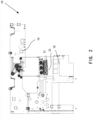
FIG. 2 shows a side sectional view of the hot foil stamping and die-cutting equipment according to the present invention, wherein the hot foil stamping and die-cutting equipment is in a bronzing working mode. -
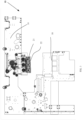
FIG. 3 shows a side sectional view of the hot foil stamping and die-cutting equipment according to the present invention, wherein the hot foil stamping and die-cutting equipment is in a die-cutting working mode. -
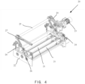
FIG. 4 shows a stereoscopic diagram of an advance-shaft transition apparatus according to the present invention. -
- 10 hot foil stamping die-cutting equipment
- 16 top equipment frame
- 18a lower base of the equipment
- 100 feeding station
- 200 platen station
- 300 foil-feeding and stripping station
- 400 delivery station
- 500 conveying apparatus
- 20 advance shaft transition apparatus
- 21 advance shaft
- 22 advance shaft supporting means
- 23 driving means
- 24 lift member
- 25 transmission rod
- 26 pulley
- 27 accommodating guide
- 29 transmission chain
- Hereinafter, the present invention will be described further in conjunction with particular embodiments and accompanying drawings. More details are illustrated in the following description for sufficient understanding of the present invention, however, the present invention can be implemented in many other manners different from what is described here obviously. A person skilled in the art can make similar promotions and deductions without departing from the essence of the present invention as required and thus the protection scope of the present invention shall not be limited by the disclosure of these particular embodiments, but only by the claims.
-
FIG. 1 shows a schematic diagram of hot foil stamping and die-cutting equipment 10 used in the field of paperboard packaging. The hot foil stamping and die-cutting equipment 10 consists of a plurality of stations, and has a hot foil stamping working mode and a die-cutting working mode. Generally, along a direction of a main conveying path of sheets in the hot foil stamping and die-cutting equipment 10, the hot foil stamping and die-cutting equipment 10 sequentially includes: afeeding station 100, thefeeding station 100 being used for feeding sheets, such as paperboards, to the hot foil stamping and die-cutting equipment 10; aplaten station 200, a plating machine being arranged at thestation 200 so as to carry out forming machining of pressing-cutting, embossing, stamping and the like; a foil-feeding andstripping station 300, thestation 300 being used for conveying of a hot-ironed foil material or stripping processing after die-cutting; and adelivery station 400, the station enabling a machined sheet to reform a stack so as to facilitate subsequent machining steps. Moreover, a conveyingapparatus 500, which includes such as conveying chain and locking means for clamping sheets provided on the chain, for conveying the sheets between each station is also arranged in theequipment 10. - For the hot foil stamping working mode and the die-cutting working mode of the hot foil stamping and die-
cutting equipment 10, arrangement structures in the foil-feeding andstripping station 300 need to be subjected to transition. - When the hot foil stamping and die-
cutting equipment 10 is adopted to carry out bronzing processing, there is at least oneadvance shaft 21 arranged in thestation 300, and theadvance shaft 21 is arranged at a position close to alower base 18 of the equipment, as shown inFIG. 2 , so as to guide the foil material to move forwards to carry out bronzing processing. The foil material is fed to theplaten station 200 by theadvance shafts 21, a to-be-machined sheet is also conveyed to theplaten station 200 from thefeeding station 100 along the main conveying path, and the foil material and the to-be-machined sheet simultaneously pass through a space between a top platen and a bottom platen which form a die-cutting machine so as to execute proper hot foil stamping processing. - When the hot foil stamping and die-
cutting equipment 10 is adopted to carry out die-cutting machining, theadvance shafts 21 in thestation 300 is moved to a position below, which is close to atop equipment frame 16 of the equipment, as shown inFIG. 3 , a stripping apparatus is mounted in thestation 300, and meanwhile, the platens of theplaten station 200 are replaced with machining tools for die-cutting, so that the sheet fed to thestation 200 from thefeeding station 100 is subjected to die-cutting machining on theplaten station 200, then the sheet subjected to die-cutting machining is conveyed to thestripping station 300 by theconveying apparatus 500, and on thestripping station 300, theequipment 10 carries out stripping processing on the sheet. - According to the present invention, the hot foil stamping and die-
cutting equipment 10 is particularly provided with an advanceshaft transition apparatus 20 on the foil-feeding andstripping station 300, which is used for carrying out transfer transition on an arrangement position of theadvance shaft 21 in the equipment machining mode switching process. - As shown in
FIG. 2 , the advanceshaft transition apparatus 20 mainly includes a plurality ofadvance shafts 21 for feeding a hot-stamping material, such as a metal foil, to a stamping area in the hot stamping device, an advance shaft supportingmeans 22 for supporting theadvance shaft 21 and a lifting means for moving theadvance shaft 21. -
FIG. 4 shows threeadvance shafts 21, but more or feweradvance shafts 21 may also be arranged according to actual demands. Thoseadvance shafts 21 are arranged basically in parallel with each other along a horizontal direction, and can rotate to propel the foil material for hot stamping towards the stamping area in theplaten station 200. - As shown in
FIG. 4 , the advanceshaft supporting means 22 is configured in a frame structure, and it preferably includes two brackets for respectively supporting the opposite ends of eachadvance shaft 21, and both ends of theadvance shaft 21 are respectively rotatably supported by two brackets of the advanceshaft supporting means 22. A driving apparatus for theadvance shaft 21 may also be fixed on one side of the advance shaft supporting means 22 so as to carry out rotary driving on theadvance shaft 21. - The lifting means of the advance
shaft transition apparatus 20 includes a driving means 23 and a transmission means. The driving means 23 is configured to produce a driving force, and the transmission means is configured to transmit the driving force to the advanceshaft supporting means 22. Specifically, the transmission means is connected between the driving means 23 and the advanceshaft supporting frame 22. The driving means 23 drives the transmission means to enable the advance shaft supporting means 22 together with the advance shafts thereon to move between a first position and a second position. As shown inFIG. 2 , in the first position, theadvance shaft 21 is located in an operation position, that is, when the supportingmeans 22 moves into the first position, the hot stamping and die cutting device is in the hot stamping mode, wherein theadvance shafts 21 are operably rotated to feed the hot-stamping material, such as a metallic foil, towards the a stamping area. As shown inFIG. 3 , when the supportingmeans 22 moves into the second position, the supportingmeans 22 brings theadvance shaft 21 into a non-operation position to give access to an operation area. The second position is a position to which theadvance shaft 21 is lifted to from the first position when the device is in the die-cutting mode, and in the second position, the supportingmeans 22 and theadvance shafts 21 thereon are moved close to atop equipment frame 16 of the device. - According to a preferred embodiment of the present invention, the driving means 23 in the lifting means adopts a motor. The
motor 23 is preferably and fixedly mounted on thetop equipment frame 16 of the hot stamping device, and mounted outside of the end portion of theadvance shaft 21. The end portion of a driving shaft of themotor 23 may be directly mounted to atransmission rod 25. Alternatively, as shown inFIG. 4 , the end portion of the driving shaft of themotor 23 is connected to the end portion of thetransmission rod 25 by atransmission chain 29. In order to the rotary motion of themotor 23 to be transferred to thetransmission rod 25 at a proper transmission ratio, thetransmission chain 29 can surround a driving wheel positioned at the end of the driving shaft of the motor and a driven wheel positioned at the end portion of thetransmission rod 25, and two wheels are arranged at a proper transmission ratio. - It shall be noted that the driving means 23 for producing a driving force is not limited to the embodiment, it may be configured by other actuating means, for example, the driving means comprise one or more of a motor, a belt, a chain, a cable, hydraulics and pneumatics.
- In the present embodiment and as shown in
FIG. 4 , the transmission means includes thetransmission rod 25, two sets of liftingmembers 24 symmetrically arranged at both ends of thetransmission rod 25 and a plurality ofpulleys 26. Thepulleys 26 can also be mounted on thetop equipment frame 16. The liftingmembers 24 are preferably configured as liftingbelts 24, one ends of two sets of liftingbelts 24 surround the ends of thetransmission rod 25 and are engaged with the ends of thetransmission rod 25, then the lifting belts bypass thepulleys 26, and the other ends of the liftingbelts 26 are fixedly connected to the advanceshaft supporting frame 22. Thus, when themotor 23 rotates the thetransmission rod 25 in a first direction, the liftingbelts 24 around the end of thetransmission rod 25 and thepulleys 26 can lift up the shaft supporting means 22, and correspondingly lift up theadvance shafts 21. If themotor 23 rotates thetransmission rod 25 in a second reverse direction, and the liftingbelts 24 can enable the shaft supporting means 22 to be descended, and accordingly descend theadvance shafts 21. - In the embodiment, the rotary motion of the driving means 23 in the transmission mean is subjected to transition into the perpendicular motion perpendicular to the direction of the horizontal plane so as to perpendicularly lift the
advance shafts 21 to the second position from the first position, and such a moving path is convenient. - The advance
shaft transition apparatus 20 of the present invention is further particularly provided with accommodating mechanisms for accommodating the ends of the liftingbelts 26. - According to a preferred embodiment in
FIG. 4 , in the embodiment, the accommodating mechanism is configured into a form of anaccommodating guide 27, and a guide slot is formed in theaccommodating guide 27. - Preferably, the
accommodating guides 27 are symmetrically arranged at both ends of thetransmission rod 25, and are used for synchronously accommodating the ends of the liftingbelts 24 at both sides. The guide slots in theaccommodating guides 27 can accommodate the end portions of the liftingbelts 24 extending out of the ends of thetransmission rod 25 when theadvance shaft 21 is lifted up. Theaccommodating rods 27 are preferably arranged at the ends of thetransmission rod 25 and are perpendicular to a plane of the axis of thetransmission rod 25. A length of theaccommodating guide 27 corresponds to a distance between the first position and the second position. - In the embodiment, the
accommodating guide 27 is arranged separately, but theaccommodating guide 27 may also be integrated into thetop equipment frame 16 to become one portion of thetop equipment frame 16 . - The transmission means for transmitting the driving force from the driving means to the shaft supporting means can be configured as other form, such as the transmission means may comprises a belt, chain, gear, pulley and/or rod.
- Moreover, the lifting means may be also provided with a limiting switch for limiting a lifting and descending position of the
advance shaft 21, and when the lifting means is lifted up or descended to a preset position, the limiting switch is actuated, so that the lifting means stops moving. - The lifting means according to the present invention can conveniently move an advance shaft assembly including the advance shafting 21 and the supporting
frame 22 between the mode transition process of the hot foil stamping and die-cuttingequipment 10, and an operator does not need to manually carry out transition of the arrangement of the advance shaft assembly. - The hot foil stamping and die-cutting
equipment 10 is provided with the top equipment frame and a lower base on the foil-feeding and strippingstation 300 of the hot foil stamping and die-cuttingequipment 10, the lifting means of the advanceshaft transition apparatus 20 is generally fixed on the top equipment frame of the equipment, and the advance shaft of the advance shaft transition apparatus and the supportingframe 22 for supporting the advance shaft are movably arranged in a space between the top equipment frame and the lower base. Assuming that the hot foil stamping and die-cuttingequipment 10 is originally in a hot foil stamping operation mode, at the moment, the advance shaft is moved to the first position close to the lower base by the lifting means, and moreover, the stamping material, such as the foil film, bypasses theadvance shaft 21 to be fed to thestation 200; when the operator inputs an instruction, the driving means 23 in the advanceshaft transition apparatus 20 rotates to actuate, the shaft supporting means is actuated by the liftingbelts 24 to be lifted up to leave the first position and stops until reaching the second position close to the top equipment frame, and the advance shafts are in the non-operation position, then an operator mounts a stripping apparatus which needs to be used in the die-cutting operation in the lower base of theequipment 10, and at the moment, theequipment 10 is subjected to transition into a die-cutting operation mode. - By adopting the advance shaft transition apparatus according to the present invention, convenience in transition of the hot foil stamping and die-cutting
equipment 10 between the bronzing and die-cutting modes is obviously improved. - According to the solution of the present invention, the existing hot foil stamping and die-cutting
equipment 10 can be improved, and the lifting means of the advanceshaft transition apparatus 20 sufficiently utilizes the space of the top equipment frame and can be easily combined into existing sheet equipment. - Although the present invention is disclosed as above with preferred embodiments, the present invention is not limited thereto and a person skilled in the art may make possible variations and modifications without departing from the scope of the present invention as defined by the claims. Thus, any modifications, equivalent changes and variations made to the above embodiments all fall into the protection scope defined by the claims of the present invention.
Claims (13)
- Hot foil stamping equipment provided with an advance shaft transition apparatus (20) comprising:at least one advance shaft (21) for feeding foils to a stamping area;advance shaft supporting means (22), the advance shaft supporting means supporting at least part of at least one advance shaft in a manner that the at least one advance shaft can rotate;characterized in, thatlifting means connected to the advance shaft supporting means enable the at least one advance shaft to move between a first position and a second position, whereinat the first position, the at least one advance shaft (21) being in an operation position, andat the second position, the at least one advance shaft (21) being in a non-operation position to give access to an operation area,the hot foil stamping equipment having a hot foil stamping working mode and a die-cutting working mode,wherein when the hot foil stamping die-cutting equipment is in the hot foil stamping working mode, the advance shafts are positioned at the first position, and when the hot foil stamping die-cutting equipment is in the die-cutting working mode, the advance shafts are positioned at the second position.
- Hot foil stamping equipment according to claim 1, wherein the advance shaft supporting means comprise a frame, supporting the at least one advance shaft at its extremities.
- Hot foil stamping equipment according to claim 1, wherein the lifting means comprise a handle, driving means and/or transmission means.
- Hot foil stamping equipment according to claim 3, wherein the driving means comprise one or more of a motor, a belt, a chain, a cable, hydraulics and pneumatics.
- Hot foil stamping equipment according to claim 3, wherein the transmission means comprises a belt, chain, gear, pulley and/or rod.
- Hot foil stamping equipment according to claim 4, wherein the driving means comprise a motor, the transmission means comprise a lifting member (24), the lifting member being connected to the advance shaft supporting means and the motor enabling the lifting member to extend and retract.
- Hot foil stamping equipment according to claim 6, wherein the transmission means further include a plurality of pulleys (26), and the lifting member (24) are arranged around the pulleys.
- Hot foil stamping equipment according to claim 6, wherein the transmission means further include a transmission rod (25) driven by the driving means (23), the transmission rod extending substantially parallel to the at least one advance shaft (21), one end of the lifting member being engaged with the transmission rod and the other end of the lifting member being engaged with the advance shaft supporting means (22).
- Hot foil stamping equipment according to claim 8, wherein the advance shaft supporting means includes a first bracket for supporting a first end of the at least one advance shaft and a second bracket for supporting a second end of the at least one advance shaft; andthe transmission means include first lifting member connecting to the first bracket and second lifting member connected to the second bracket,the first lifting member is respectively connected to a first end of the transmission rod (25) and the first bracket, andthe second lifting member is respectively connected to a second end of the transmission rod (25) and the second bracket.
- Hot foil stamping equipment according to claim 8, wherein the lifting means further includes an accommodating guide (27) for accommodating an end portion of the lifting member (24), and the accommodating guide (27) is arranged in a plane perpendicular to the transmission rod (25).
- Hot foil stamping equipment according to claim 4, wherein the motor is mounted outside of the end of the advance shaft (21).
- Hot foil stamping equipment according to claim 1, wherein the lifting means move the advance shafts to the second position from the first position in a direction basically perpendicular to a horizontal plane.
- The hot foil stamping equipment according to any of claims 1 to 12,
comprising:a feeding station (100), the feeding station being used for feeding sheets to the hot foil stamping die-cutting equipment;a platen station (200), the platen station being positioned on the downstream of the feeding station along a sheet conveying direction and used for carrying out pressing-cutting or embossing machining on the sheets;a foil-feeding and stripping station (300), the foil-feeding and stripping station being positioned on the downstream of the platen station along a sheet conveying path; anda delivery station (400), the delivery station being positioned on the downstream of the foil-feeding and stripping station and used for enabling the machined sheets to form a sheet stack,wherein the advance shaft transition apparatus is arranged in the foil-feeding and stripping station, and when the hot foil stamping die-cutting equipment is in a die-cutting mode, the advance shaft is moved to the second position, and a stripping apparatus is arranged below the advance shafts.
Applications Claiming Priority (2)
| Application Number | Priority Date | Filing Date | Title |
|---|---|---|---|
| CN201810179141.2A CN110228289B (en) | 2018-03-05 | 2018-03-05 | Roller shaft conversion device and gold stamping die cutting equipment |
| PCT/IB2019/051713 WO2019171239A1 (en) | 2018-03-05 | 2019-03-04 | Advance-shaft transition apparatus and hot foil stamping and die-cutting equipment |
Publications (3)
| Publication Number | Publication Date |
|---|---|
| EP3762232A1 EP3762232A1 (en) | 2021-01-13 |
| EP3762232A4 EP3762232A4 (en) | 2021-12-01 |
| EP3762232B1 true EP3762232B1 (en) | 2025-05-07 |
Family
ID=67846933
Family Applications (1)
| Application Number | Title | Priority Date | Filing Date |
|---|---|---|---|
| EP19763825.7A Active EP3762232B1 (en) | 2018-03-05 | 2019-03-04 | Advance-shaft transition apparatus and hot foil stamping and die-cutting equipment |
Country Status (8)
| Country | Link |
|---|---|
| US (1) | US11981045B2 (en) |
| EP (1) | EP3762232B1 (en) |
| JP (1) | JP7128898B2 (en) |
| KR (1) | KR102400941B1 (en) |
| CN (1) | CN110228289B (en) |
| ES (1) | ES3031210T3 (en) |
| TW (1) | TWI701152B (en) |
| WO (1) | WO2019171239A1 (en) |
Families Citing this family (3)
| Publication number | Priority date | Publication date | Assignee | Title |
|---|---|---|---|---|
| CN110228289B (en) * | 2018-03-05 | 2022-07-15 | 博斯特(上海)有限公司 | Roller shaft conversion device and gold stamping die cutting equipment |
| CN111268480B (en) * | 2020-03-25 | 2021-08-17 | 东莞市艾尔玛塑件科技有限公司 | A transfer printing equipment with non-stop material change |
| EP4112306B1 (en) * | 2021-07-01 | 2025-03-26 | Bobst Mex Sa | Hot foil stamping press |
Family Cites Families (36)
| Publication number | Priority date | Publication date | Assignee | Title |
|---|---|---|---|---|
| DE2254281A1 (en) * | 1972-11-06 | 1974-05-22 | Hillesheimer Walter Dipl Ing D | DEVICE FOR PUNCHING SHAPES OR MATERIAL LINES |
| JPS5155085A (en) | 1974-11-07 | 1976-05-14 | Kyoto Seisakusho | Itagamino jidoshorihansosochi |
| JPS59119758A (en) | 1982-12-25 | 1984-07-11 | Toshiba Corp | Manufacture of semiconductor device |
| US4603611A (en) * | 1984-07-06 | 1986-08-05 | Ferguson Dennis R | Feed system for punch press |
| JPS6135796U (en) * | 1984-07-31 | 1986-03-05 | 岡村印刷工業株式会社 | Male type of stripping machine |
| USRE34125E (en) * | 1987-06-02 | 1992-11-10 | Stanwich Industries, Inc. | Roller hold down device |
| US5275684A (en) * | 1991-10-16 | 1994-01-04 | Automated Laser Personalization Systems, Inc. | Transfer unit for printing systems |
| JPH0834112A (en) * | 1994-07-21 | 1996-02-06 | Sony Corp | Transfer device |
| JPH08183521A (en) * | 1994-12-28 | 1996-07-16 | Sekisui Plastics Co Ltd | Labeling machine |
| JPH0999501A (en) * | 1995-10-05 | 1997-04-15 | Maruzen Kk | Manufacturing method and manufacturing equipment for plastic files |
| JPH10203095A (en) | 1997-01-22 | 1998-08-04 | Toyohashi Hotsuto Sutanpu Kk | Method and machine for thermal transfer |
| JP4142871B2 (en) * | 2001-12-27 | 2008-09-03 | 株式会社シード | Mark transfer tool, mark transfer tape, and method of manufacturing mark transfer tape |
| CN2784185Y (en) * | 2005-03-31 | 2006-05-31 | 上海耀科印刷机械有限公司 | Multi-station flat-crushing automatic hot-stamping and die-cutting machine |
| DE102006051349A1 (en) * | 2006-10-31 | 2008-05-08 | Sms Demag Ag | Method and device for dividing metal strip |
| CN201020918Y (en) * | 2007-03-24 | 2008-02-13 | 王昌盛 | Gas-liquid reinforcement bronzing die-cutting machine |
| CN101524912A (en) * | 2009-04-21 | 2009-09-09 | 上海新闵太阳机械有限公司 | Multifunctional complex printer |
| CN201456541U (en) * | 2009-07-23 | 2010-05-12 | 上海亚华印刷机械有限公司 | An automatic hot stamping machine integrating hot stamping, die cutting and waste stripping functions |
| CN102380972A (en) | 2010-09-01 | 2012-03-21 | 上海亚华印刷机械有限公司 | Equipment capable of completing indenting, die cutting and finished-product receiving and stacking by one-step paper feeding |
| RU2537283C2 (en) * | 2010-09-16 | 2014-12-27 | Бобст Мекс Са | Printing device with use of embossing |
| RU2555402C1 (en) * | 2011-02-28 | 2015-07-10 | Бобст Мекс Са | Foil unwinder for stamping press |
| JP5801591B2 (en) | 2011-04-11 | 2015-10-28 | 日本写真印刷株式会社 | Thermal transfer apparatus and thermal transfer method |
| CN102248765A (en) * | 2011-05-31 | 2011-11-23 | 中山市松德包装机械股份有限公司 | Combined intelligent printing machine |
| DE102011054221A1 (en) | 2011-10-06 | 2013-04-11 | Peter Barth | Print finishing process and device therefor |
| KR101633211B1 (en) | 2012-03-28 | 2016-06-23 | 봅스트 맥스 에스에이 | Module for supplying a strip to be stamped |
| CN203282835U (en) * | 2013-06-11 | 2013-11-13 | 云南恩典科技产业发展有限公司 | Continuous axial adjustment device with variable gilding rubber roll length |
| CN104339300B (en) * | 2013-07-25 | 2016-06-08 | 博斯特(上海)有限公司 | A kind of assembly tool being simultaneously suitable for die-cutting machine and gilding press |
| US10029385B2 (en) * | 2014-05-12 | 2018-07-24 | Lloyd R. Hoover | Workpiece holddown apparatus for a bandsaw |
| CN105800630A (en) | 2014-12-29 | 2016-07-27 | 陈建 | Method for preparing SAPO-31 molecular sieve from kaolin |
| CN105800360A (en) * | 2014-12-31 | 2016-07-27 | 博斯特(上海)有限公司 | Paper tension control and storage device |
| DE102015213171B3 (en) | 2015-07-14 | 2017-01-19 | Koenig & Bauer Ag | Web processing device and a method for transporting at least one material web along at least one web transport path of a web processing device |
| CN205523000U (en) | 2016-01-21 | 2016-08-31 | 浙江大源机械有限公司 | Useless cross cutting machine of gilt qing dynasty |
| CN105538412A (en) * | 2016-01-21 | 2016-05-04 | 浙江大源机械有限公司 | Hot stamping waste cleaning die-cutting machine |
| CN205364080U (en) | 2016-02-22 | 2016-07-06 | 林友士 | Multi -functional cross cutting of full -automatic compact machine |
| CN106628338B (en) * | 2016-11-04 | 2017-11-28 | 深圳市龙锋泰自动化有限公司 | The on-line automatic overlay film system of glass production line |
| CN207028335U (en) * | 2017-07-12 | 2018-02-23 | 中山市新宏业自动化工业有限公司 | A kind of gold-stamping die-cutting window opener |
| CN110228289B (en) * | 2018-03-05 | 2022-07-15 | 博斯特(上海)有限公司 | Roller shaft conversion device and gold stamping die cutting equipment |
-
2018
- 2018-03-05 CN CN201810179141.2A patent/CN110228289B/en active Active
-
2019
- 2019-02-13 TW TW108104775A patent/TWI701152B/en active
- 2019-03-04 KR KR1020207028085A patent/KR102400941B1/en active Active
- 2019-03-04 ES ES19763825T patent/ES3031210T3/en active Active
- 2019-03-04 JP JP2020546458A patent/JP7128898B2/en active Active
- 2019-03-04 WO PCT/IB2019/051713 patent/WO2019171239A1/en not_active Ceased
- 2019-03-04 EP EP19763825.7A patent/EP3762232B1/en active Active
- 2019-03-04 US US16/978,617 patent/US11981045B2/en active Active
Also Published As
| Publication number | Publication date |
|---|---|
| KR20200125981A (en) | 2020-11-05 |
| KR102400941B1 (en) | 2022-05-20 |
| TW201938397A (en) | 2019-10-01 |
| CN110228289A (en) | 2019-09-13 |
| EP3762232A4 (en) | 2021-12-01 |
| JP2021516634A (en) | 2021-07-08 |
| WO2019171239A1 (en) | 2019-09-12 |
| CN110228289B (en) | 2022-07-15 |
| US20200406491A1 (en) | 2020-12-31 |
| EP3762232A1 (en) | 2021-01-13 |
| ES3031210T3 (en) | 2025-07-07 |
| JP7128898B2 (en) | 2022-08-31 |
| US11981045B2 (en) | 2024-05-14 |
| TWI701152B (en) | 2020-08-11 |
Similar Documents
| Publication | Publication Date | Title |
|---|---|---|
| US11981045B2 (en) | Advance-shaft transition apparatus and hot foil stamping and die-cutting equipment | |
| KR101124063B1 (en) | Paper-made binder, and system and device for producing the same | |
| US11331902B2 (en) | Blowing means unit and hot foil stamping and die-cutting device | |
| CN210944211U (en) | Paper conveyer and paper folding machine using same | |
| CN112172161A (en) | Disposable ultrasonic automatic mask point earphone | |
| KR100743689B1 (en) | Coverlay attachment system and method | |
| JP3507066B1 (en) | Die cutter unit and folding unit for sheet-like work | |
| CN209940088U (en) | Paper folding machine with automatic folding function | |
| CN111509092B (en) | Feeding device and busbar hot pressing machine | |
| US10391522B2 (en) | Cleaning device for a processing platen press | |
| CN209940087U (en) | Improved paper folding machine | |
| CN216266371U (en) | Fixed-length cutting device for multi-mesh-belt screen printing machine | |
| CN112847619A (en) | A cutting machine for POF crosslinked membrane | |
| EP4188687B1 (en) | Machine for wrapping already formed boxes with a covering sheet | |
| CN108116931B (en) | Automatic film sticking machine for index card | |
| CN208020710U (en) | Curved surface protective film mold automatic production equipment | |
| CN111989220A (en) | Drive device for stamping foil, stamping station and stamping machine and method for controlling drive of stamping foil | |
| CN219650094U (en) | Double-optical-axis supporting directional die cutting machine | |
| EP1369212A2 (en) | A die cutting machine | |
| CN115674340A (en) | Die cutting equipment capable of adjusting die cutting angle and die cutting processing method | |
| CN120916875A (en) | Device for processing a predominantly bending-rigid material web or sheet and method for changing the configuration of such a device | |
| WO2022196122A1 (en) | Workpiece transport device |
Legal Events
| Date | Code | Title | Description |
|---|---|---|---|
| STAA | Information on the status of an ep patent application or granted ep patent |
Free format text: STATUS: THE INTERNATIONAL PUBLICATION HAS BEEN MADE |
|
| PUAI | Public reference made under article 153(3) epc to a published international application that has entered the european phase |
Free format text: ORIGINAL CODE: 0009012 |
|
| STAA | Information on the status of an ep patent application or granted ep patent |
Free format text: STATUS: REQUEST FOR EXAMINATION WAS MADE |
|
| 17P | Request for examination filed |
Effective date: 20200824 |
|
| AK | Designated contracting states |
Kind code of ref document: A1 Designated state(s): AL AT BE BG CH CY CZ DE DK EE ES FI FR GB GR HR HU IE IS IT LI LT LU LV MC MK MT NL NO PL PT RO RS SE SI SK SM TR |
|
| AX | Request for extension of the european patent |
Extension state: BA ME |
|
| DAV | Request for validation of the european patent (deleted) | ||
| DAX | Request for extension of the european patent (deleted) | ||
| A4 | Supplementary search report drawn up and despatched |
Effective date: 20211029 |
|
| RIC1 | Information provided on ipc code assigned before grant |
Ipc: B26F 1/40 20060101ALI20211025BHEP Ipc: B65H 20/24 20060101ALI20211025BHEP Ipc: B26F 1/38 20060101ALI20211025BHEP Ipc: B65H 5/06 20060101ALI20211025BHEP Ipc: B41F 19/00 20060101ALI20211025BHEP Ipc: B26D 7/26 20060101ALI20211025BHEP Ipc: B41F 16/00 20060101ALI20211025BHEP Ipc: B41F 19/06 20060101AFI20211025BHEP |
|
| STAA | Information on the status of an ep patent application or granted ep patent |
Free format text: STATUS: EXAMINATION IS IN PROGRESS |
|
| 17Q | First examination report despatched |
Effective date: 20240229 |
|
| GRAP | Despatch of communication of intention to grant a patent |
Free format text: ORIGINAL CODE: EPIDOSNIGR1 |
|
| STAA | Information on the status of an ep patent application or granted ep patent |
Free format text: STATUS: GRANT OF PATENT IS INTENDED |
|
| GRAS | Grant fee paid |
Free format text: ORIGINAL CODE: EPIDOSNIGR3 |
|
| INTG | Intention to grant announced |
Effective date: 20250228 |
|
| GRAA | (expected) grant |
Free format text: ORIGINAL CODE: 0009210 |
|
| STAA | Information on the status of an ep patent application or granted ep patent |
Free format text: STATUS: THE PATENT HAS BEEN GRANTED |
|
| AK | Designated contracting states |
Kind code of ref document: B1 Designated state(s): AL AT BE BG CH CY CZ DE DK EE ES FI FR GB GR HR HU IE IS IT LI LT LU LV MC MK MT NL NO PL PT RO RS SE SI SK SM TR |
|
| REG | Reference to a national code |
Ref country code: GB Ref legal event code: FG4D |
|
| REG | Reference to a national code |
Ref country code: CH Ref legal event code: EP |
|
| REG | Reference to a national code |
Ref country code: DE Ref legal event code: R096 Ref document number: 602019069652 Country of ref document: DE |
|
| REG | Reference to a national code |
Ref country code: IE Ref legal event code: FG4D |
|
| REG | Reference to a national code |
Ref country code: ES Ref legal event code: FG2A Ref document number: 3031210 Country of ref document: ES Kind code of ref document: T3 Effective date: 20250707 |
|
| REG | Reference to a national code |
Ref country code: NL Ref legal event code: MP Effective date: 20250507 |
|
| PG25 | Lapsed in a contracting state [announced via postgrant information from national office to epo] |
Ref country code: PT Free format text: LAPSE BECAUSE OF FAILURE TO SUBMIT A TRANSLATION OF THE DESCRIPTION OR TO PAY THE FEE WITHIN THE PRESCRIBED TIME-LIMIT Effective date: 20250908 Ref country code: FI Free format text: LAPSE BECAUSE OF FAILURE TO SUBMIT A TRANSLATION OF THE DESCRIPTION OR TO PAY THE FEE WITHIN THE PRESCRIBED TIME-LIMIT Effective date: 20250507 |
|
| REG | Reference to a national code |
Ref country code: LT Ref legal event code: MG9D |
|
| PG25 | Lapsed in a contracting state [announced via postgrant information from national office to epo] |
Ref country code: GR Free format text: LAPSE BECAUSE OF FAILURE TO SUBMIT A TRANSLATION OF THE DESCRIPTION OR TO PAY THE FEE WITHIN THE PRESCRIBED TIME-LIMIT Effective date: 20250808 Ref country code: NO Free format text: LAPSE BECAUSE OF FAILURE TO SUBMIT A TRANSLATION OF THE DESCRIPTION OR TO PAY THE FEE WITHIN THE PRESCRIBED TIME-LIMIT Effective date: 20250807 |
|
| PG25 | Lapsed in a contracting state [announced via postgrant information from national office to epo] |
Ref country code: NL Free format text: LAPSE BECAUSE OF FAILURE TO SUBMIT A TRANSLATION OF THE DESCRIPTION OR TO PAY THE FEE WITHIN THE PRESCRIBED TIME-LIMIT Effective date: 20250507 Ref country code: PL Free format text: LAPSE BECAUSE OF FAILURE TO SUBMIT A TRANSLATION OF THE DESCRIPTION OR TO PAY THE FEE WITHIN THE PRESCRIBED TIME-LIMIT Effective date: 20250507 |
|
| REG | Reference to a national code |
Ref country code: AT Ref legal event code: MK05 Ref document number: 1792062 Country of ref document: AT Kind code of ref document: T Effective date: 20250507 |
|
| PG25 | Lapsed in a contracting state [announced via postgrant information from national office to epo] |
Ref country code: BG Free format text: LAPSE BECAUSE OF FAILURE TO SUBMIT A TRANSLATION OF THE DESCRIPTION OR TO PAY THE FEE WITHIN THE PRESCRIBED TIME-LIMIT Effective date: 20250507 |
|
| PG25 | Lapsed in a contracting state [announced via postgrant information from national office to epo] |
Ref country code: HR Free format text: LAPSE BECAUSE OF FAILURE TO SUBMIT A TRANSLATION OF THE DESCRIPTION OR TO PAY THE FEE WITHIN THE PRESCRIBED TIME-LIMIT Effective date: 20250507 |
|
| PG25 | Lapsed in a contracting state [announced via postgrant information from national office to epo] |
Ref country code: AT Free format text: LAPSE BECAUSE OF FAILURE TO SUBMIT A TRANSLATION OF THE DESCRIPTION OR TO PAY THE FEE WITHIN THE PRESCRIBED TIME-LIMIT Effective date: 20250507 |
|
| PG25 | Lapsed in a contracting state [announced via postgrant information from national office to epo] |
Ref country code: RS Free format text: LAPSE BECAUSE OF FAILURE TO SUBMIT A TRANSLATION OF THE DESCRIPTION OR TO PAY THE FEE WITHIN THE PRESCRIBED TIME-LIMIT Effective date: 20250807 |
|
| PG25 | Lapsed in a contracting state [announced via postgrant information from national office to epo] |
Ref country code: IS Free format text: LAPSE BECAUSE OF FAILURE TO SUBMIT A TRANSLATION OF THE DESCRIPTION OR TO PAY THE FEE WITHIN THE PRESCRIBED TIME-LIMIT Effective date: 20250907 |
|
| PG25 | Lapsed in a contracting state [announced via postgrant information from national office to epo] |
Ref country code: LV Free format text: LAPSE BECAUSE OF FAILURE TO SUBMIT A TRANSLATION OF THE DESCRIPTION OR TO PAY THE FEE WITHIN THE PRESCRIBED TIME-LIMIT Effective date: 20250507 |
|
| PG25 | Lapsed in a contracting state [announced via postgrant information from national office to epo] |
Ref country code: SM Free format text: LAPSE BECAUSE OF FAILURE TO SUBMIT A TRANSLATION OF THE DESCRIPTION OR TO PAY THE FEE WITHIN THE PRESCRIBED TIME-LIMIT Effective date: 20250507 Ref country code: DK Free format text: LAPSE BECAUSE OF FAILURE TO SUBMIT A TRANSLATION OF THE DESCRIPTION OR TO PAY THE FEE WITHIN THE PRESCRIBED TIME-LIMIT Effective date: 20250507 |
|
| PG25 | Lapsed in a contracting state [announced via postgrant information from national office to epo] |
Ref country code: CZ Free format text: LAPSE BECAUSE OF FAILURE TO SUBMIT A TRANSLATION OF THE DESCRIPTION OR TO PAY THE FEE WITHIN THE PRESCRIBED TIME-LIMIT Effective date: 20250507 |
|
| PG25 | Lapsed in a contracting state [announced via postgrant information from national office to epo] |
Ref country code: EE Free format text: LAPSE BECAUSE OF FAILURE TO SUBMIT A TRANSLATION OF THE DESCRIPTION OR TO PAY THE FEE WITHIN THE PRESCRIBED TIME-LIMIT Effective date: 20250507 |
|
| PG25 | Lapsed in a contracting state [announced via postgrant information from national office to epo] |
Ref country code: SK Free format text: LAPSE BECAUSE OF FAILURE TO SUBMIT A TRANSLATION OF THE DESCRIPTION OR TO PAY THE FEE WITHIN THE PRESCRIBED TIME-LIMIT Effective date: 20250507 Ref country code: RO Free format text: LAPSE BECAUSE OF FAILURE TO SUBMIT A TRANSLATION OF THE DESCRIPTION OR TO PAY THE FEE WITHIN THE PRESCRIBED TIME-LIMIT Effective date: 20250507 |
|
| REG | Reference to a national code |
Ref country code: DE Ref legal event code: R097 Ref document number: 602019069652 Country of ref document: DE |
|
| PLBE | No opposition filed within time limit |
Free format text: ORIGINAL CODE: 0009261 |
|
| STAA | Information on the status of an ep patent application or granted ep patent |
Free format text: STATUS: NO OPPOSITION FILED WITHIN TIME LIMIT |
|
| REG | Reference to a national code |
Ref country code: CH Ref legal event code: L10 Free format text: ST27 STATUS EVENT CODE: U-0-0-L10-L00 (AS PROVIDED BY THE NATIONAL OFFICE) Effective date: 20260318 |
|
| REG | Reference to a national code |
Ref country code: CH Ref legal event code: U11 Free format text: ST27 STATUS EVENT CODE: U-0-0-U10-U11 (AS PROVIDED BY THE NATIONAL OFFICE) Effective date: 20260401 |
|
| PGFP | Annual fee paid to national office [announced via postgrant information from national office to epo] |
Ref country code: GB Payment date: 20260324 Year of fee payment: 8 |
|
| PGFP | Annual fee paid to national office [announced via postgrant information from national office to epo] |
Ref country code: DE Payment date: 20260319 Year of fee payment: 8 |
|
| 26N | No opposition filed |
Effective date: 20260210 |
|
| PGFP | Annual fee paid to national office [announced via postgrant information from national office to epo] |
Ref country code: IT Payment date: 20260324 Year of fee payment: 8 |
|
| PGFP | Annual fee paid to national office [announced via postgrant information from national office to epo] |
Ref country code: FR Payment date: 20260323 Year of fee payment: 8 |