EP3761812B1 - Aerosolerzeugende artikel - Google Patents
Aerosolerzeugende artikel Download PDFInfo
- Publication number
- EP3761812B1 EP3761812B1 EP19706633.5A EP19706633A EP3761812B1 EP 3761812 B1 EP3761812 B1 EP 3761812B1 EP 19706633 A EP19706633 A EP 19706633A EP 3761812 B1 EP3761812 B1 EP 3761812B1
- Authority
- EP
- European Patent Office
- Prior art keywords
- aerosol
- core
- sleeve
- cores
- generating article
- Prior art date
- Legal status (The legal status is an assumption and is not a legal conclusion. Google has not performed a legal analysis and makes no representation as to the accuracy of the status listed.)
- Active
Links
- 239000000443 aerosol Substances 0.000 title claims description 138
- 239000011162 core material Substances 0.000 claims description 212
- 238000001125 extrusion Methods 0.000 claims description 41
- 239000000463 material Substances 0.000 claims description 32
- 238000000034 method Methods 0.000 claims description 32
- 230000037361 pathway Effects 0.000 claims description 21
- 238000004519 manufacturing process Methods 0.000 claims description 14
- 239000004626 polylactic acid Substances 0.000 claims description 13
- 229920000747 poly(lactic acid) Polymers 0.000 claims description 7
- WTLNOANVTIKPEE-UHFFFAOYSA-N 2-acetyloxypropanoic acid Chemical compound OC(=O)C(C)OC(C)=O WTLNOANVTIKPEE-UHFFFAOYSA-N 0.000 claims description 2
- 229920002678 cellulose Polymers 0.000 claims description 2
- 239000001913 cellulose Substances 0.000 claims description 2
- 238000001816 cooling Methods 0.000 description 32
- 238000005520 cutting process Methods 0.000 description 26
- 230000007246 mechanism Effects 0.000 description 12
- 230000000391 smoking effect Effects 0.000 description 7
- 239000000758 substrate Substances 0.000 description 7
- 238000011144 upstream manufacturing Methods 0.000 description 5
- 238000012795 verification Methods 0.000 description 5
- 239000002826 coolant Substances 0.000 description 4
- 239000002994 raw material Substances 0.000 description 4
- 238000009736 wetting Methods 0.000 description 4
- 241000208125 Nicotiana Species 0.000 description 3
- 235000002637 Nicotiana tabacum Nutrition 0.000 description 3
- 238000004590 computer program Methods 0.000 description 3
- 239000002657 fibrous material Substances 0.000 description 3
- 230000001953 sensory effect Effects 0.000 description 3
- 238000000926 separation method Methods 0.000 description 3
- XLYOFNOQVPJJNP-UHFFFAOYSA-N water Substances O XLYOFNOQVPJJNP-UHFFFAOYSA-N 0.000 description 3
- 230000004323 axial length Effects 0.000 description 2
- 230000005540 biological transmission Effects 0.000 description 2
- 235000019504 cigarettes Nutrition 0.000 description 2
- 150000001875 compounds Chemical class 0.000 description 2
- 238000001914 filtration Methods 0.000 description 2
- 239000000796 flavoring agent Substances 0.000 description 2
- 235000019634 flavors Nutrition 0.000 description 2
- 239000007788 liquid Substances 0.000 description 2
- 229920000642 polymer Polymers 0.000 description 2
- 230000008569 process Effects 0.000 description 2
- 239000011347 resin Substances 0.000 description 2
- 229920005989 resin Polymers 0.000 description 2
- 210000003296 saliva Anatomy 0.000 description 2
- 239000007787 solid Substances 0.000 description 2
- 239000000126 substance Substances 0.000 description 2
- NOOLISFMXDJSKH-UTLUCORTSA-N (+)-Neomenthol Chemical compound CC(C)[C@@H]1CC[C@@H](C)C[C@@H]1O NOOLISFMXDJSKH-UTLUCORTSA-N 0.000 description 1
- NOOLISFMXDJSKH-UHFFFAOYSA-N DL-menthol Natural products CC(C)C1CCC(C)CC1O NOOLISFMXDJSKH-UHFFFAOYSA-N 0.000 description 1
- 239000000654 additive Substances 0.000 description 1
- 238000004026 adhesive bonding Methods 0.000 description 1
- 229920002301 cellulose acetate Polymers 0.000 description 1
- 230000008859 change Effects 0.000 description 1
- 238000006243 chemical reaction Methods 0.000 description 1
- 230000001055 chewing effect Effects 0.000 description 1
- 238000002485 combustion reaction Methods 0.000 description 1
- 238000010276 construction Methods 0.000 description 1
- 230000003247 decreasing effect Effects 0.000 description 1
- 239000012467 final product Substances 0.000 description 1
- 239000010419 fine particle Substances 0.000 description 1
- 239000007789 gas Substances 0.000 description 1
- 238000010438 heat treatment Methods 0.000 description 1
- 230000003993 interaction Effects 0.000 description 1
- 239000013067 intermediate product Substances 0.000 description 1
- 229940041616 menthol Drugs 0.000 description 1
- 238000002156 mixing Methods 0.000 description 1
- 239000012768 molten material Substances 0.000 description 1
- 239000002245 particle Substances 0.000 description 1
- 229920003023 plastic Polymers 0.000 description 1
- 239000004033 plastic Substances 0.000 description 1
- 125000006850 spacer group Chemical group 0.000 description 1
Images
Classifications
-
- A—HUMAN NECESSITIES
- A24—TOBACCO; CIGARS; CIGARETTES; SIMULATED SMOKING DEVICES; SMOKERS' REQUISITES
- A24D—CIGARS; CIGARETTES; TOBACCO SMOKE FILTERS; MOUTHPIECES FOR CIGARS OR CIGARETTES; MANUFACTURE OF TOBACCO SMOKE FILTERS OR MOUTHPIECES
- A24D3/00—Tobacco smoke filters, e.g. filter-tips, filtering inserts; Filters specially adapted for simulated smoking devices; Mouthpieces for cigars or cigarettes
- A24D3/02—Manufacture of tobacco smoke filters
- A24D3/0229—Filter rod forming processes
- A24D3/0237—Filter rod forming processes by extrusion
-
- A—HUMAN NECESSITIES
- A24—TOBACCO; CIGARS; CIGARETTES; SIMULATED SMOKING DEVICES; SMOKERS' REQUISITES
- A24D—CIGARS; CIGARETTES; TOBACCO SMOKE FILTERS; MOUTHPIECES FOR CIGARS OR CIGARETTES; MANUFACTURE OF TOBACCO SMOKE FILTERS OR MOUTHPIECES
- A24D1/00—Cigars; Cigarettes
- A24D1/04—Cigars; Cigarettes with mouthpieces or filter-tips
- A24D1/045—Cigars; Cigarettes with mouthpieces or filter-tips with smoke filter means
-
- A—HUMAN NECESSITIES
- A24—TOBACCO; CIGARS; CIGARETTES; SIMULATED SMOKING DEVICES; SMOKERS' REQUISITES
- A24D—CIGARS; CIGARETTES; TOBACCO SMOKE FILTERS; MOUTHPIECES FOR CIGARS OR CIGARETTES; MANUFACTURE OF TOBACCO SMOKE FILTERS OR MOUTHPIECES
- A24D1/00—Cigars; Cigarettes
- A24D1/20—Cigarettes specially adapted for simulated smoking devices
-
- A—HUMAN NECESSITIES
- A24—TOBACCO; CIGARS; CIGARETTES; SIMULATED SMOKING DEVICES; SMOKERS' REQUISITES
- A24D—CIGARS; CIGARETTES; TOBACCO SMOKE FILTERS; MOUTHPIECES FOR CIGARS OR CIGARETTES; MANUFACTURE OF TOBACCO SMOKE FILTERS OR MOUTHPIECES
- A24D3/00—Tobacco smoke filters, e.g. filter-tips, filtering inserts; Filters specially adapted for simulated smoking devices; Mouthpieces for cigars or cigarettes
- A24D3/02—Manufacture of tobacco smoke filters
-
- A—HUMAN NECESSITIES
- A24—TOBACCO; CIGARS; CIGARETTES; SIMULATED SMOKING DEVICES; SMOKERS' REQUISITES
- A24D—CIGARS; CIGARETTES; TOBACCO SMOKE FILTERS; MOUTHPIECES FOR CIGARS OR CIGARETTES; MANUFACTURE OF TOBACCO SMOKE FILTERS OR MOUTHPIECES
- A24D3/00—Tobacco smoke filters, e.g. filter-tips, filtering inserts; Filters specially adapted for simulated smoking devices; Mouthpieces for cigars or cigarettes
- A24D3/04—Tobacco smoke filters characterised by their shape or structure
-
- A—HUMAN NECESSITIES
- A24—TOBACCO; CIGARS; CIGARETTES; SIMULATED SMOKING DEVICES; SMOKERS' REQUISITES
- A24D—CIGARS; CIGARETTES; TOBACCO SMOKE FILTERS; MOUTHPIECES FOR CIGARS OR CIGARETTES; MANUFACTURE OF TOBACCO SMOKE FILTERS OR MOUTHPIECES
- A24D3/00—Tobacco smoke filters, e.g. filter-tips, filtering inserts; Filters specially adapted for simulated smoking devices; Mouthpieces for cigars or cigarettes
- A24D3/06—Use of materials for tobacco smoke filters
- A24D3/062—Use of materials for tobacco smoke filters characterised by structural features
- A24D3/066—Use of materials for tobacco smoke filters characterised by structural features in the form of foam or having cellular structure
-
- A—HUMAN NECESSITIES
- A24—TOBACCO; CIGARS; CIGARETTES; SIMULATED SMOKING DEVICES; SMOKERS' REQUISITES
- A24D—CIGARS; CIGARETTES; TOBACCO SMOKE FILTERS; MOUTHPIECES FOR CIGARS OR CIGARETTES; MANUFACTURE OF TOBACCO SMOKE FILTERS OR MOUTHPIECES
- A24D3/00—Tobacco smoke filters, e.g. filter-tips, filtering inserts; Filters specially adapted for simulated smoking devices; Mouthpieces for cigars or cigarettes
- A24D3/06—Use of materials for tobacco smoke filters
- A24D3/067—Use of materials for tobacco smoke filters characterised by functional properties
- A24D3/068—Biodegradable or disintegrable
-
- A—HUMAN NECESSITIES
- A24—TOBACCO; CIGARS; CIGARETTES; SIMULATED SMOKING DEVICES; SMOKERS' REQUISITES
- A24D—CIGARS; CIGARETTES; TOBACCO SMOKE FILTERS; MOUTHPIECES FOR CIGARS OR CIGARETTES; MANUFACTURE OF TOBACCO SMOKE FILTERS OR MOUTHPIECES
- A24D3/00—Tobacco smoke filters, e.g. filter-tips, filtering inserts; Filters specially adapted for simulated smoking devices; Mouthpieces for cigars or cigarettes
- A24D3/06—Use of materials for tobacco smoke filters
- A24D3/08—Use of materials for tobacco smoke filters of organic materials as carrier or major constituent
- A24D3/10—Use of materials for tobacco smoke filters of organic materials as carrier or major constituent of cellulose or cellulose derivatives
-
- A—HUMAN NECESSITIES
- A24—TOBACCO; CIGARS; CIGARETTES; SIMULATED SMOKING DEVICES; SMOKERS' REQUISITES
- A24D—CIGARS; CIGARETTES; TOBACCO SMOKE FILTERS; MOUTHPIECES FOR CIGARS OR CIGARETTES; MANUFACTURE OF TOBACCO SMOKE FILTERS OR MOUTHPIECES
- A24D3/00—Tobacco smoke filters, e.g. filter-tips, filtering inserts; Filters specially adapted for simulated smoking devices; Mouthpieces for cigars or cigarettes
- A24D3/17—Filters specially adapted for simulated smoking devices
-
- A—HUMAN NECESSITIES
- A24—TOBACCO; CIGARS; CIGARETTES; SIMULATED SMOKING DEVICES; SMOKERS' REQUISITES
- A24F—SMOKERS' REQUISITES; MATCH BOXES; SIMULATED SMOKING DEVICES
- A24F42/00—Simulated smoking devices other than electrically operated; Component parts thereof; Manufacture or testing thereof
- A24F42/60—Constructional details
-
- A—HUMAN NECESSITIES
- A24—TOBACCO; CIGARS; CIGARETTES; SIMULATED SMOKING DEVICES; SMOKERS' REQUISITES
- A24F—SMOKERS' REQUISITES; MATCH BOXES; SIMULATED SMOKING DEVICES
- A24F42/00—Simulated smoking devices other than electrically operated; Component parts thereof; Manufacture or testing thereof
- A24F42/80—Manufacture
-
- B—PERFORMING OPERATIONS; TRANSPORTING
- B29—WORKING OF PLASTICS; WORKING OF SUBSTANCES IN A PLASTIC STATE IN GENERAL
- B29C—SHAPING OR JOINING OF PLASTICS; SHAPING OF MATERIAL IN A PLASTIC STATE, NOT OTHERWISE PROVIDED FOR; AFTER-TREATMENT OF THE SHAPED PRODUCTS, e.g. REPAIRING
- B29C48/00—Extrusion moulding, i.e. expressing the moulding material through a die or nozzle which imparts the desired form; Apparatus therefor
- B29C48/001—Combinations of extrusion moulding with other shaping operations
- B29C48/0022—Combinations of extrusion moulding with other shaping operations combined with cutting
-
- B—PERFORMING OPERATIONS; TRANSPORTING
- B29—WORKING OF PLASTICS; WORKING OF SUBSTANCES IN A PLASTIC STATE IN GENERAL
- B29C—SHAPING OR JOINING OF PLASTICS; SHAPING OF MATERIAL IN A PLASTIC STATE, NOT OTHERWISE PROVIDED FOR; AFTER-TREATMENT OF THE SHAPED PRODUCTS, e.g. REPAIRING
- B29C48/00—Extrusion moulding, i.e. expressing the moulding material through a die or nozzle which imparts the desired form; Apparatus therefor
- B29C48/16—Articles comprising two or more components, e.g. co-extruded layers
-
- B—PERFORMING OPERATIONS; TRANSPORTING
- B29—WORKING OF PLASTICS; WORKING OF SUBSTANCES IN A PLASTIC STATE IN GENERAL
- B29C—SHAPING OR JOINING OF PLASTICS; SHAPING OF MATERIAL IN A PLASTIC STATE, NOT OTHERWISE PROVIDED FOR; AFTER-TREATMENT OF THE SHAPED PRODUCTS, e.g. REPAIRING
- B29C48/00—Extrusion moulding, i.e. expressing the moulding material through a die or nozzle which imparts the desired form; Apparatus therefor
- B29C48/25—Component parts, details or accessories; Auxiliary operations
- B29C48/30—Extrusion nozzles or dies
- B29C48/345—Extrusion nozzles comprising two or more adjacently arranged ports, for simultaneously extruding multiple strands, e.g. for pelletising
-
- B—PERFORMING OPERATIONS; TRANSPORTING
- B29—WORKING OF PLASTICS; WORKING OF SUBSTANCES IN A PLASTIC STATE IN GENERAL
- B29L—INDEXING SCHEME ASSOCIATED WITH SUBCLASS B29C, RELATING TO PARTICULAR ARTICLES
- B29L2031/00—Other particular articles
- B29L2031/7414—Smokers'' requisites, e.g. pipe cleaners
- B29L2031/7416—Smokers'' requisites, e.g. pipe cleaners for cigars or cigarettes
Definitions
- This invention relates generally to aerosol generating articles. More specifically, although not exclusively, this invention relates aerosol permeation elements used in tubular shaped aerosol generating articles including, in particular, such aerosol generating articles configured to heat aerosol forming substrates without burning them. This invention also relates to methods of manufacturing such articles and elements.
- the filter part or cooling part of an aerosol generating article performs several functions and, as such, several of its properties must be considered in its design and manufacture.
- the main role of the filter part is filtration or cooling efficiency, namely its effectiveness in removing unwanted components of the aerosol, but this must always be balanced with the overall resistance to draw, which is the pressure drop experienced as the aerosol passes through the filter.
- An additional complication with aerosol generating articles configured to heat aerosol forming substrates without burning them is that the quantity of sensory media tends to be more closely packed. As such, the inherent resistance to draw provided by the sensory media in such aerosol generating articles is generally much higher than that of traditional combustible aerosol generating articles.
- the filter part of an aerosol generating article can often experience significant compressive forces exerted thereon by the consumer. Some consumers also enjoy chewing the filter part and often have expectations as to its resistance to compressibility.
- the structure of the filter part must be able to withstand such forces, whilst both continuing to perform its main function.
- the filter part must also continue to function despite exposure to saliva and should minimise or prevent its transmission therethrough to avoid wetting of the aerosol forming substrate.
- One known method of manufacturing filter parts of aerosol generating articles involves pulling a continuous rod of filter material, for instance cellulose acetate, on a moving band of wrapping paper, which is closed and glued around the rod.
- the continuous wrapped rod is then cut into lengths or sticks, which are then joined to the rest of the aerosol generating article by a tipping paper, which provides the requisite resistance to wetting.
- the wrapping paper is generally hard for resisting mouth pressure, which makes it difficult to shape. Moreover, it can impact the taste of the aerosol and the gluing process can present challenges.
- PLA poly lactic acid
- WO2013/187676 discloses a cigarette filter including a sub-filter portion surrounded by a filter wrapping paper, a space portion with an empty space next to the sub-filter portion, and a polylactic acid (PLA) laminated paper surrounding the sub-filter portion and the space portion.
- PLA polylactic acid
- WO2013/068337 discloses a smoking article comprising a flavour release segment.
- the flavour release segment comprises a plug of fibrous material circumscribed by a substantially air impermeable wrapper and a plurality of solid menthol particles distributed within the plug of fibrous material.
- the fibrous material comprises randomly oriented fibres.
- WO2014/060455 discloses a smoking article wrapper and method of making a smoking article.
- a smoking article component comprises a curved sheet wrapper of weight 40 gsm or more that includes a plurality of lines of strength discontinuity at which the wrapper presents a visually discernible non-uniformity in its curvature.
- the wrapper can be used for example to wrap the filter of a cigarette as a plug wrap for the filter so as to comprise a wrapper of weight 80 gsm or more.
- a first aspect of the invention provides an aerosol generating article as defined in claim 1 of the appended claims.
- an integral sleeve that is longer than the core enables a portion of the integral sleeve to be used as an interface with the rest of the aerosol generating article, thereby providing an effective alternative to prior art constructions.
- free space or gap might enable a further cooling or mixing of aerosol before delivery to a user.
- the length of the core may be between 2 millimetres and 10 millimetres, for example between 3 millimetres and 8 millimetres, such as between 4 millimetres and 7 millimetres.
- the length of the sleeve may be between 20 millimetres and 200 millimetres, for example between 60 millimetres and 150 millimetres, such as between 50 millimetres and 120 millimetres.
- the core may be 80 percent or 75 percent or less, for example no more than half of the length of the sleeve. In embodiments, the core is between 2 percent and 15 percent, such as between 4 percent and 7 percent, of the length of the sleeve.
- the aerosol permeation element may comprise one end or side that may be hollow, for example, a first end or a hollow end or a first hollow end.
- the aerosol permeation element may comprise another or second end or side, for example, with the aerosol permeable core therein.
- the sleeve comprises a polymeric extrusion.
- the sleeve may comprise a poly lactic acid material, for example an extruded poly lactic acid material or other polymeric compound or extruded poly lactic acid material and other polymeric compounds.
- the sleeve comprises a thickness, for example a wall thickness, of between 0.1 millimetres and 4 millimetres, for example between 0.2 millimetres and 3 millimetres.
- the sleeve comprises a thickness of between 0.3 millimetres and 2 millimetres, such as 0.5 millimetres and 1.5 millimetres.
- the core may comprise a polymeric extrusion, which may be foamed or may have one or more pathways described therealong, or may be foamed and have one or more pathways described therealong. At least one of the pathways may be described within the core extrusion. Alternatively or in addition at least one of the pathways may be described by a channel on an outer surface thereof, for example which cooperates with the sleeve. At least one or each pathway may be helical or helicoidal.
- the core may comprise a poly lactic acid, acetate or cellulose material.
- the core may comprise one or more drawn clusters of fibres, which may comprise a wrap, for example, a paper or plastic wrap, surrounding the drawn fibres.
- the core may be between 2 millimetres and 9 millimetres, for example, the core may comprise a diameter of between 2 millimetres and 9 millimetres.
- the core is between 4 millimetres and 6 millimetres, for example the core comprises a diameter of between 4 millimetres and 7.5 millimetres.
- the outer sleeve might be further wrapped into a wrapper, such as paper, to give a specific appearance to the permeation element.
- the aerosol generating article comprises an aerosol generating or sensorial material, for example tobacco.
- the aerosol generating article comprises a rod of aerosol generating or sensorial material, which may be connected, secured or attached to the aerosol permeation element, by way of a portion thereof being received within the hollow end.
- the aerosol generating article comprises a further sleeve within which the aerosol generating or sensorial material is received.
- the further sleeve may be connected, secured or attached to the aerosol permeation element, for example a portion thereof may be received within the hollow end.
- An external wrapper might also secure the elements together.
- Another aspect of the invention provides a method of manufacturing an aerosol permeation element as defined in claim 8 of the appended claims.
- an integral sleeve can be formed having spaces of a predetermined length, thereby providing a series of integral aerosol permeation elements which can then be separated to provide the aerosol permeation elements described above.
- the method may comprise conveying the plurality of aerosol permeable cores using a conveying means or conveyor.
- the method may comprise forming the sleeve around each core using a sleeve forming means or former.
- the method may comprise separating, for example, cutting or severing, the sleeve or the or each core or the sleeve and the or each core, for example to form a series of aerosol permeation elements.
- the method may comprise separating the sleeve or each core or sleeve and each core, using a separation means or separator.
- the sleeve may be separated between each core, for example at or adjacent a first end of each core or at a location substantially equidistant from each adjacent core.
- the sleeve and core may both be separated at or adjacent the centre or a central portion of the core.
- the series of aerosol permeation elements may be formed such that each of the aerosol permeation elements comprises a first, hollow end and a second end with at least part of one of the cores.
- each core is equivalent to the length required for each aerosol permeation elements.
- the sleeve may be separated at or adjacent a first end of each core.
- each core may be longer than, for example, double the length of, the length required for each aerosol permeation elements.
- the method may comprise separating both the sleeve and each core at one or more or a series of first positions or separating the sleeve, for example only the sleeve, at one or more or a series of second positions, for example, between each consecutive pair of cores.
- Each first position may be at or adjacent the centre or a central portion of one of the cores.
- Each second position may be at a location substantially equidistant from each adjacent core.
- the method may comprise supplying an extrusion to form the plurality of cores, for example using a core delivery means.
- the method may comprise separating or cutting or severing the extrusion, for example using a core cutting means or station.
- the extrusion may be continuous or may have one or more pathways described therealong or may be continuous and have one or more pathways described therealong.
- the method may comprise extruding a core material, for example through a core die, to form the extrusion.
- the method may comprise supplying the extrusion from the core die to form the plurality of cores.
- the method may comprise drawing the extrusion through a cooling media or bath.
- the extrusion may be drawn such that it forms a substantially conical shape, for example downstream of the core die or between the core die and the cooling media or bath.
- the method may comprise supplying the extrusion as a pre-formed extrusion.
- the method may comprise supplying the extrusion from a delivery device, such as a roll.
- the method may comprise extruding a sleeve material, for example through a sleeve die, to form the sleeve around the cores.
- the method may comprise drawing the extruded sleeve containing cores, for example at the second speed or rate.
- the cores may be supplied through the sleeve die, for example through a passage, an opening or aperture, which may be central, through the sleeve die.
- the sleeve die may comprise an outlet having or forming a diameter or annulus which surrounds the passage. In specific embodiments the sleeve die is larger, for example, substantially larger, than the cores.
- the method may comprise drawing the extruded sleeve containing cores such that the sleeve extrusion forms a substantially conical shape, for example downstream of the sleeve die.
- the method may comprise drawing the extruded sleeve containing cores through a cooling media or bath.
- the method may comprise drawing the extruded sleeve containing cores through a secondary die or diameter verification device.
- the extruded sleeve containing cores may be drawn such that the sleeve extrusion forms a substantially conical shape between the sleeve die and the cooling media or bath.
- the extruded sleeve containing cores may be drawn such that the sleeve extrusion forms a substantially conical shape between the sleeve die and the secondary die or diameter verification device.
- the method may further comprise combining the aerosol permeation element with a rod containing sensory media, for example, tobacco.
- the aerosol generating article comprises an aerosol generating or sensorial material, for example tobacco.
- the aerosol generating article comprises a rod of aerosol generating or sensorial material, which may be connected, secured or attached to the aerosol permeation element, by way of a portion thereof being received within the hollow end.
- the aerosol generating article comprises a further sleeve within which the aerosol generating or sensorial material is received. The further sleeve may be connected, secured or attached to the aerosol permeation element, for example a portion thereof may be received within the hollow end.
- a series of integral aerosol permeation elements for use in aerosol generating articles may be provided, the series comprising a plurality of cores spaced from one another within a sleeve formed integrally therearound.
- the series of integral aerosol permeation elements may comprise an intermediate product of the aforementioned method of manufacturing aerosol permeation elements.
- An aerosol permeation element of an aerosol generating article may comprise a severed section of a series of integral aerosol permeation elements as described above.
- Another aspect of the invention provides an apparatus for manufacturing an aerosol permeation element of an aerosol generating article as defined in claim 14 of the appended claims.
- the sleeve forming means may comprise a sleeve extruder, for example, for extruding the sleeve around each core.
- the sleeve forming means may comprise a sleeve die, which may comprise an inlet from which sleeve material, for example, molten sleeve material, is received, in use, from the sleeve extruder.
- the sleeve die may comprise a central passage, for example an opening or aperture.
- the conveying path may pass through the central passage.
- the conveying means may be configured or operable to convey, in use, a plurality of aerosol permeable cores through the central passage.
- the sleeve die may comprise an outlet, which may surround the conveying path or central passage or both the conveying path and central passage, for example, for supplying, in use, extruded sleeve material around a plurality of cores passing through the central passage.
- the apparatus may comprise a drawing means, mechanism or device, which may be downstream of the sleeve forming means, for drawing the sleeve containing cores.
- the drawing means may comprise a pulling device, which may comprise a motor and a conveying means or conveyor for pulling or drawing the sleeve containing cores.
- the conveying means may comprise one or more, such as a set or pair of, pulling rollers.
- the apparatus may comprise an aerosol permeation element separation means or separator.
- the apparatus or separation means may comprise a cutting means or station, for example, for cutting the formed sleeve and core into a plurality of aerosol permeation elements.
- the cutting means or station may be downstream of the sleeve forming means or drawing means or downstream of both the sleeve forming means and drawing means.
- the cutting means may be for separating, cutting or severing a sleeve or core exiting the sleeve forming means, or separating, cutting or severing both the sleeve and core exiting the sleeve forming means, to form a series, for example the aforementioned series, of aerosol permeation elements.
- the apparatus may comprise a core delivery means or device, for example, for delivering the plurality of cores to the conveying means.
- the core delivery means may comprise a core cutting means or station, for example, for receiving and severing a continuous extrusion to form the plurality of cores.
- the core delivery means comprises a supply, for example a roll, of pre-formed core extrusion.
- the supply may be operatively connected to the core cutting means, for example, for supplying the pre-formed core extrusion to the core cutting means.
- the apparatus or core delivery means may comprise a core forming means or former.
- the core forming means may comprise a core extruder, for example, for forming an extrusion, which may be continuous or may have one or more pathways described therealong or may be continuous and have one or more pathways described therealong.
- the core forming means may comprise a core die, which may comprise a female portion or part or one or more male portions or parts or both female and male portions or parts.
- the female portion or part may comprise an outer wall, for example, for forming an outer surface of the extrusion.
- the or each male portion or part may comprise a core, which may be suspended or secured within the female portion.
- the or each male portion or part may be configured or suitable for forming one of the pathways along the extrusion.
- the male portion or part may be rotatable, for example within the female part, for example, such that the core members create helical or helicoidal pathways within the extrusion.
- the core forming means may comprise a core cooling means, such as a cooling bath that may comprise or contain cooling media therein.
- the core cooling means may be downstream of the core extruder or core die or downstream of both the core extruder and the core die.
- the core forming means may comprise a core drawing means, mechanism or device, which may be downstream of the core extruder or core die or core cooling means or any combination thereof, for drawing the core extrusion.
- the core forming means may be configured such that the core extrusion is drawn, in use, to form a substantially conical shape, for example downstream of the core die or between the core die and the core cooling means.
- the core forming means may be configured or operable to vary the speed of rotation of the male part relative to a speed at which the core is drawn, for example, to create a predetermined helical angle of the pathways.
- the core drawing means, mechanism or device may comprise a motor and a conveying means or conveyor for pulling or drawing the sleeve containing cores.
- the conveying means may comprise a pulling device, which may comprise one or more, such as a set or pair of, pulling rollers.
- the core cutting means may be downstream of the core extruder or core die or core drawing means, or any combination thereof.
- the aerosol generating article may comprise any one or more features of the aerosol permeation element or series of aerosol permeation elements or vice versa.
- the method may comprise any one or more features or steps relevant to one or more features of the aerosol permeation element, the series of aerosol permeation elements or aerosol generating article.
- specific embodiments may further comprise a computer program element comprising computer readable program code means for causing a processor to execute a procedure to implement one or more steps of the aforementioned method.
- specific embodiments may further comprise a computer program element embodied on a computer readable medium.
- specific embodiments may further comprise a computer readable medium having a program stored thereon, where the program is arranged to make a computer execute a procedure to implement one or more steps of the aforementioned method.
- specific embodiments may further comprise a control means or control system or controller comprising the aforementioned computer program element or computer readable medium.
- aerosol generating article refers to an article comprising an aerosol forming substrate that is capable of releasing volatile compounds that can form an aerosol, for example by heating, combustion or chemical reaction.
- aerosol forming substrate is used to describe a substrate capable of releasing volatile compounds, which can form an aerosol.
- the aerosols generated from the aerosol forming substrates of aerosol generating articles according to the invention may be visible or invisible and may include vapours (for example, fine particles of substances, which are in the gaseous state, that are ordinarily liquid or solid at room temperature) as well as gases and liquid droplets of condensed vapours.
- sheet denotes a laminar element having a width and length greater than the thickness thereof.
- aerosol permeation element is used to describe an element that allows permeation of an aerosol through it, partially or fully.
- the aerosol permeation element will be, but not limited to, a filter, a spacer or a cooling element.
- the aerosol permeation element may have a combination of functions.
- the term “sleeve” is used to describe a partial or full cover. Ideally partially covering the longitudinal outer surface of the core of the aerosol permeation element.
- the term “core”, as used herein, is used to describe the inner portion of the aerosol permeation element at least partially covered by the sleeve of the aerosol permeation element.
- upstream and downstream refer to relative positions of elements of the aerosol generating article described in relation to the direction of inhalation air flow as it is drawn through the body of the aerosol generating article from a distal, tip end to the mouthpiece end.
- downstream is defined relative to air flow during use of the smoking article or aerosol generating article, with the mouthpiece end of the article being the downstream end through which air and aerosol is drawn. The end opposite the mouthpiece end is the upstream end.
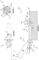
- FIG. 1 and 2 there is shown two variations of an aerosol permeation element or filter part 1, 1' according to embodiments of the invention for use in an aerosol generating article (shown in outline).
- the filter part 1, 1' includes an aerosol permeable core 2 of extruded polymeric filter material within an extruded polymeric sleeve 3 surrounding it.
- the core 2 has a plurality of pathways 21 described within it and the configuration shown in Figure 2 also includes a plurality of channels 22 described in an outer surface thereof.
- the pathways 21 and channels 22 extend along the axial length L1 of the core 2.
- the core 2 has first end surface 23 and second end surface 24, spaced from one another by the distance L1.
- the core 2 is formed from a poly lactic acid (PLA) material in this embodiment and has a diameter D of 5 millimetres.
- PLA poly lactic acid
- the sleeve 3 surrounds and is formed integrally with the core 2 and is also formed from poly lactic acid (PLA) in this embodiment.
- the sleeve 3 has a wall thickness W of 1 millimetre and an axial length L2.
- the length L2 of the sleeve 3 is greater than the length L1 of the core 2, such that the filter part 1, 1' has a hollow end 4 beyond the first end surface 23 of the core 2.
- the second end 24 of the core 2 is aligned with an end surface of the sleeve 3.
- the channels 22 in the outer surface of the core 2 define, together with the internal surface of the sleeve 3, pathways 25.
- the hollow end 4 of the filter part 1, 1' allows part of the aerosol generating article to be mounted therein to provide a degree of overlapping interface between the aerosol generating article and the filter part 1, 1'.
- the inner surface of the sleeve 3 may provide a friction fit with another part of the aerosol generating article.
- the sleeve 3 extends the entire length of the aerosol generating article, such that the aerosol generating substance is contained within the hollow end 4.
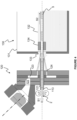
- the apparatus 100 includes a core feed 110, which feeds cores 2 through an extrusion die 120 at a predetermined speed S1. Extruded sleeve material is fed continuously from a screw extruder 125 through the die 120 and is deposited on the cores 2 to form a continuous length of filter rod 5.
- the filter rod 5 is drawn from the die 120 at speed S2, which is greater than core feed speed S1. This difference in speed (S2 - S1) creates a space between consecutive cores 2 within the extruded sleeve material.
- the so-formed filter rod 5 is drawn through a cooling unit 130 downstream of the die 120 using a drawing mechanism 140 and on to a cutting station 150 for severing the continuous length of filter rod 5 to produce a plurality of filter parts 1, 1'.
- the filter feed 110 has a pair of opposed, counter-rotating feed rollers 111, 112 configured to rotate at speed R1 to provide the core feed speed S1.
- a feed tube 113 is provided downstream of the feed rollers 111, 112.
- the feed tube 113 has an inner diameter slightly greater than the diameter D of the cores 2.
- the feed tube 113 is configured to correctly position each respective core 2 as it is fed into the die 120 and protrudes from both the upstream and downstream sides of the die 120.
- the die 120 has a central aperture 121 through which the feed tube 113.
- the die 120 also has a feed channel 122, which feeds into an annular chamber 123 and out through an annular passage 124.
- the extruder 125 has a hopper 126 for feeding raw material thereto, which is melted and fed into the annular chamber 123.
- the raw material is in the form of poly lactic acid (PLA) resin in this embodiment.
- the cooling unit 130 Downstream of the die 120 is the cooling unit 130, which includes a tank 131 containing a cooling medium, which is water 132 in this embodiment. Extruded material is drawn from the annular passage 124 of the die 120, into a cooling inlet 133 in a wall of the tank 131 and through a diameter verification device 134, which is below the surface of the water 132.
- the diameter verification device 134 is tubular with an internal diameter which is substantially the same as the diameter of the filter rod 5 and substantially smaller than the annular passage 124. As such, the extruded material forms a conical tube as it passes from the annular passage 124 of the die to the cooling inlet 133 of the tank 131.
- the drawing mechanism 140 is downstream of the cooling unit 130 and includes a pair of opposed, counter-rotating pulling rollers 141, 142 arranged to receive the filter rod 5 after it has passed through the cooling unit 130.
- the pulling rollers 141, 142 receive the filter rod 5 therebetween, draw it through the cooling unit 130 and covey it towards the cutting station 150 at speed S2.
- the cutting station 150 has an inlet 151, a cutter (not shown) for cutting the filter rod 5 into filter parts 1, 1' and an outlet 152 through which the filter parts 1, 1' are expelled.
- cores 2 are fed into the feed tube 113 by the feed rollers 111, 112. Each successive core 2 fed into the feed tube 113 pushes the others along the conveying direction of the apparatus 100 and into the die 120. As the cores 2 are conveyed, they pass through the die 120 and exit the feed tube 113 into the conical tubular extrusion of material as it enters the cooling inlet 133 of the tank 131.
- the sleeve material from the annular passage 124 of the die 120 is drawn at speed S2 as it contacts each core 2 and enters the cooling inlet 133 of tank 131.
- the cores 2 are drawn into the cooling inlet 133 of the tank 131 at speed S2 as they come into contact with extruded sleeve material from the die 120, which creates a space between consecutive cores 2 in the filter rod 5.
- the filter rod 5 As the filter rod 5 is drawn through the cooling unit 130 by the drawing mechanism 140, it cools and solidifies the extruded sleeve 3. The filter rod 5 is also drawn through the diameter verification device 134 which ensures the diameter of the filter rod 5 is correct. The filter rod 5 is then fed into the cutting station 150 through the inlet 151 and is cut to form the filter parts 1, 1', which then exit the cutting station 150 through the outlet 152.
- the filter rod 5 may be cut into regular segments by providing a first cut through the core 2 and sleeve 3 at the midpoint of the core 2 and a second cut through the sleeve 3 at the midpoint of the space between adjacent cores 2.
- This cutting arrangement produces filter parts 1, 1' with a core 2 having length L1 which is half of the length of the core 2 supplied to the apparatus 100 at the core feed 110.
- This cutting arrangement also produces a sleeve 3 with a length L2, which greater than L1.
- the filter part 1, 1' has the hollow end 4 adjacent the first end 23 of the core 2 and the second end 24 of the core 2 aligned with an end surface of the sleeve 3.
- the cores 2 supplied to the apparatus 100 may have a length equal to L1, wherein the sleeve 3 of the filter rod 5 is simply cut adjacent the second end 24 of each consecutive core 2.
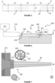
- Figures 6 and 7 show an optional core former 200 for use with the apparatus 100.
- the core former 200 includes an extruder 210, which forms a continuous extruded core 6 through a core die 220.
- the extruded core 6 is drawn from the core die 220 through a cooling unit 230 using a core drawing mechanism 240. Downstream of the core drawing mechanism 240, the extruded core 6 is fed into a core cutting station 250, which severs the extruded core 6 to produce a plurality of cores 2 for supply to the apparatus 100.
- the core extruder 210 has a hopper 211 for feeding raw material, a poly lactic acid (PLA) resin in this embodiment, to the core extruder 210.
- a flow channel 212 leading to the core die 220.
- the core die 220 has a male part 221 and a female part 222 described by an outer wall 223 that defines the outer surface of the extrusion.
- the male part 221 is supported within the female part 222 by support elements (not shown) and has a plurality of core members 224 each having a circular cross-section for creating the pathways 21 within the extrusion.
- the circular core members 224 together define a star pattern so as to form the pathways 21 along the extrusion 6.
- the core die 220 is attached to the outlet of the core extruder 210 for receiving molten material therefrom.
- the male part 221 may rotate within the female part 222 such that the core members 224 create helical or helicoidal pathways 21 within the extrusion.
- the helical angle of the pathways 21 may be controlled by the speed of rotation of the male part 221 relative to the drawing speed of the extrusion.
- the cooling unit 230 Downstream of the core die 220 is the cooling unit 230 which, similar to the cooling unit 130 of apparatus 100, includes a tank 231 having a cooling medium therein. Extruded material 60 is drawn by the drawing mechanism 240 from the extruder 210 into a cooling inlet 232 in a wall of the tank 231, which causes it to form a conical extrusion 60 in a similar manner to the sleeve extrusion process described above.
- the drawing mechanism 240 includes a pair of opposed, counter-rotating pulling rollers 241, 242 arranged to draw the extruded core 6 from the cooling unit 230.
- the pulling rollers 241, 242 convey the extruded core 6 into the core cutting station 250, which cuts the core extrusion 6 into individual cores 2.
- raw material for forming the cores 2 is fed from the hopper 211 through the extruder 210.
- Extruded core material 60 is drawn through the cooling unit 230 by the drawing mechanism 240, which cools and solidifies it into the core extrusion 6 ready for further processing.
- the core extrusion 6 is drawn by the pulling rollers 241, 242 of the drawing mechanism 240 and fed to the cutting station 250.
- the core former 200 may be located upstream of the core feed 110 shown in Figures 3 and 4 .
- the cores 2 produced at the outlet 252 of the core cutting station 250 may be fed to the inlet of the core feed 110.
- the core former 200 is completely separate from the apparatus 100.
- the core former 200 may not have a core cutting station 250 and instead the extruded core may be stored on a roll.
- the apparatus 100 may have a core cutter upstream of the core feed 110 so as to form cores 2 prior to feeding.
- Other arrangements are also envisaged.
- the parameters of the filter part 1, 1' may be altered by changing one or more processing parameters.
- the thickness of the sleeve 3 may be increased or decreased by modifying the relationship between the drawing speed S2 and the rate at which extruded material is supplied by the extruder 125.
- the invention provides a versatile means of producing aerosol permeation elements 1 whose characteristics can be varied across a wide range.
- the cooling medium in the cooling units 130, 230 is described as being water. This need not be the case and instead, any suitable cooling medium may be used.
- the extruded sleeve 3 and core 2 may be formed of different materials to those described above. Additionally or alternatively, the core 2 may, but need not, be formed of a foamed material.
Landscapes
- Engineering & Computer Science (AREA)
- Chemical & Material Sciences (AREA)
- Materials Engineering (AREA)
- Mechanical Engineering (AREA)
- Manufacturing & Machinery (AREA)
- Life Sciences & Earth Sciences (AREA)
- Biodiversity & Conservation Biology (AREA)
- Extrusion Moulding Of Plastics Or The Like (AREA)
- Cigarettes, Filters, And Manufacturing Of Filters (AREA)
Claims (14)
- Aerosolerzeugender Artikel, umfassend:ein Aerosolpermeationselement (1, 1'), umfassend einen aerosolpermeablen Kern (2) innerhalb einer einstückig darum gebildeten extrudierten Polymerhülse (3), wobei der aerosolpermeable Kern (2) kürzer ist als die extrudierte Polymerhülse (3); das Aerosolpermeationselement (1, 1') ein hohles Ende (4) umfasst und das andere Ende (24) des Aerosolpermeationselements (1, 1') den aerosolpermeablen Kern (2) umfasst; undeinen Stock aus aerosolerzeugendem Material, wobei ein Abschnitt davon innerhalb des hohlen Endes (4) des Aerosolpermeationselements (1, 1') aufgenommen ist.
- Aerosolerzeugender Artikel nach Anspruch 1, wobei der aerosolpermeable Kern (2) nicht länger als die Hälfte der Länge der extrudierten Polymerhülse (3) ist.
- Aerosolerzeugender Artikel nach einem beliebigen vorhergehenden Anspruch, wobei der aerosolpermeable Kern (2) eine geschäumte Polymerextrusion mit einem oder mehreren entlang dieser beschriebenen Wegen (21) aufweist.
- Aerosolerzeugender Artikel nach einem beliebigen vorhergehenden Anspruch, wobei die extrudierte Polymerhülse (3) ein Polymilchsäurematerial umfasst.
- Aerosolerzeugender Artikel nach einem beliebigen vorhergehenden Anspruch, wobei der aerosolpermeable Kern (2) ein Polymilchsäure-, Acetat- oder Cellulosematerial umfasst.
- Aerosolerzeugender Artikel nach einem beliebigen vorhergehenden Anspruch, wobei die extrudierte Polymerhülse (3) eine Wanddicke zwischen 0,3 Millimeter und 3 Millimetern aufweist.
- Aerosolerzeugender Artikel nach einem beliebigen vorhergehenden Anspruch, wobei der aerosolpermeable Kern (2) einen Durchmesser zwischen 4 Millimetern und 7,5 Millimetern aufweist.
- Verfahren zur Herstellung eines Aerosolpermeationselements (1, 1') zum Gebrauch in einem aerosolerzeugenden Artikel, das Verfahren umfassend:Fördern einer Vielzahl von aerosolpermeablen Kernen (2) entlang eines Förderweges mit einer ersten Geschwindigkeit (S1); undBilden einer Hülse (3) um jeden Kern (2) mit einer zweiten Geschwindigkeit (S2), die höher ist als die erste Geschwindigkeit (S1), zum Erzeugen eines Raums zwischen aufeinanderfolgenden Kernen (2) innerhalb der Hülse (3).
- Verfahren nach Anspruch 8, umfassend das Durchtrennen der Hülse (3) zwischen angrenzenden aerosolpermeablen Kernen (2) zum Bilden einer Reihe von Aerosolpermeationselementen (1, 1'), die jeweils ein erstes, hohles Ende (4) und ein zweites Ende (24) mit wenigstens einem Teil eines der aerosolpermeablen Kerne (2) umfassen.
- Verfahren nach Anspruch 9, umfassend das Durchtrennen sowohl der Hülse (3) als auch jedes aerosolpermeablen Kerns (2) an einer Reihe von ersten Positionen und das Durchtrennen der Hülse an einer Reihe von zweiten Positionen zwischen jedem aufeinanderfolgenden Paar von aerosolpermeablen Kernen (2) zum Bilden der Reihe von Aerosolpermeationselementen (1, 1'), die jeweils ein erstes, hohles Ende (4) und ein zweites Ende (24) mit einem Teil eines der aerosolpermeablen Kerne (2) umfassen.
- Verfahren nach einem der Ansprüche 8 bis 10, umfassend das Zuführen und Abtrennen einer kontinuierlichen Extrusion (6) mit einem oder mehreren entlang dieser beschriebenen Wegen (21) zum Bilden der Vielzahl von aerosolpermeablen Kernen (2).
- Verfahren nach Anspruch 11, umfassend das Extrudieren eines Kernmaterials durch eine Kerndüse (220) zum Bilden der kontinuierlichen Extrusion (6) und das Zuführen und Abtrennen der kontinuierlichen Extrusion (6) von der Kerndüse (220) zum Bilden der Vielzahl von aerosolpermeablen Kernen (2).
- Verfahren nach einem beliebigen der Ansprüche 8 bis 12, umfassend das Extrudieren eines Hülsenmaterials durch eine Hülsendüse (120) zum Bilden der Hülse (3) um die aerosolpermeablen Kerne (2).
- Vorrichtung (100) zum Herstellen eines Aerosolpermeationselements (1, 1') eines aerosolerzeugenden Artikels, die Vorrichtung (100) umfassend:ein Fördermittel (110) oder einen Förderer zum Befördern einer Vielzahl von aerosolpermeablen Kernen (2) entlang eines Förderweges mit einer ersten Geschwindigkeit (S1); undein Hülsenformungsmittel (120) oder einen Former zum Bilden einer Hülse (3) um jeden aerosolpermeablen Kern (2) mit einer zweiten Geschwindigkeit (S2), wobei die zweite Geschwindigkeit (S2) höher ist als die erste Geschwindigkeit (S1), zum Bilden eines Raums zwischen aufeinanderfolgenden aerosolpermeablen Kernen (2) innerhalb der Hülse (3).
Applications Claiming Priority (2)
| Application Number | Priority Date | Filing Date | Title |
|---|---|---|---|
| EP18160817 | 2018-03-08 | ||
| PCT/EP2019/054546 WO2019170455A1 (en) | 2018-03-08 | 2019-02-25 | Aerosol generating articles |
Publications (3)
| Publication Number | Publication Date |
|---|---|
| EP3761812A1 EP3761812A1 (de) | 2021-01-13 |
| EP3761812C0 EP3761812C0 (de) | 2023-08-23 |
| EP3761812B1 true EP3761812B1 (de) | 2023-08-23 |
Family
ID=61691216
Family Applications (1)
| Application Number | Title | Priority Date | Filing Date |
|---|---|---|---|
| EP19706633.5A Active EP3761812B1 (de) | 2018-03-08 | 2019-02-25 | Aerosolerzeugende artikel |
Country Status (7)
| Country | Link |
|---|---|
| US (2) | US11839234B2 (de) |
| EP (1) | EP3761812B1 (de) |
| JP (1) | JP7377209B2 (de) |
| KR (1) | KR20200125606A (de) |
| CN (1) | CN111712143B (de) |
| BR (1) | BR112020015960A2 (de) |
| WO (1) | WO2019170455A1 (de) |
Families Citing this family (2)
| Publication number | Priority date | Publication date | Assignee | Title |
|---|---|---|---|---|
| IT202000014095A1 (it) | 2020-06-12 | 2021-12-12 | Montrade S P A | Metodo per la realizzazione di un prodotto da fumo, macchina per la realizzazione di un prodotto da fumo e uso di tale macchina ed un articolo da fumo così ottenuto |
| KR20220063860A (ko) * | 2020-11-10 | 2022-05-18 | 주식회사 케이티앤지 | 에어로졸 생성 물품 및 이를 포함하는 에어로졸 생성 시스템 |
Citations (2)
| Publication number | Priority date | Publication date | Assignee | Title |
|---|---|---|---|---|
| WO2014020055A1 (en) * | 2012-08-01 | 2014-02-06 | Essentra Filter Products Development Co. Pte. Ltd | Tobacco smoke filter |
| WO2014060455A1 (en) * | 2012-10-16 | 2014-04-24 | British American Tobacco (Investments) Limited | Smoking article wrapper and method of making a smoking article |
Family Cites Families (16)
| Publication number | Priority date | Publication date | Assignee | Title |
|---|---|---|---|---|
| US2979058A (en) * | 1957-01-15 | 1961-04-11 | Olin Mathieson | Manufacture of laminated filter tip |
| GB2119221B (en) | 1982-04-05 | 1986-05-29 | Filtrona Ltd | Cigarette filter |
| NO157125C (no) * | 1982-04-08 | 1988-06-01 | Filtrona Ltd | Sigarettfilterelement, alternativt med et omgivende, ventilerende munnstykkemateriale. |
| US4854331A (en) * | 1984-09-14 | 1989-08-08 | R. J. Reynolds Tobacco Company | Smoking article |
| US4869275A (en) * | 1987-02-24 | 1989-09-26 | American Filtrona Corporation | Ultra-high filtration filter |
| DE10009829A1 (de) | 2000-03-01 | 2001-09-20 | Reemtsma H F & Ph | Rauchartikel |
| JP4290000B2 (ja) | 2001-08-17 | 2009-07-01 | フィリップ・モーリス・プロダクツ・ソシエテ・アノニム | 計量された量の粒子材料で空洞を充填するデュアルステーションアプリケータホイール |
| US8464726B2 (en) * | 2009-08-24 | 2013-06-18 | R.J. Reynolds Tobacco Company | Segmented smoking article with insulation mat |
| GB201104475D0 (en) * | 2011-03-16 | 2011-04-27 | Filtrona Filter Prod Dev Co | Tobacco smoke filter |
| UA112328C2 (uk) * | 2011-11-07 | 2016-08-25 | Філіп Морріс Продактс С.А. | Ментолвмісний курильний виріб |
| GB201202220D0 (en) | 2012-02-08 | 2012-03-28 | Filtrona Filter Prod Dev Co | Tobacco smoke filter |
| KR20140143144A (ko) | 2012-03-05 | 2014-12-15 | 몬트레이드 에스.알.엘. | 필터 로드 성형 기계에 필터 재료를 공급하는 방법 및 장치 |
| KR101375774B1 (ko) | 2012-06-12 | 2014-03-18 | 주식회사 케이티앤지 | Pla 합지를 포함하는 담배 필터 및 이를 포함하는 담배 |
| TR201808121T4 (tr) | 2012-08-06 | 2018-07-23 | Philip Morris Products Sa | Ağız ucu boşluklarına sahip sigara içim ürünleri oluşturmanın metodu. |
| GB201407642D0 (en) | 2014-04-30 | 2014-06-11 | British American Tobacco Co | Aerosol-cooling element and arrangements for apparatus for heating a smokable material |
| GB201608815D0 (en) * | 2016-05-19 | 2016-07-06 | British American Tobacco Co | Filter rod and apparatus and method |
-
2019
- 2019-02-25 CN CN201980013071.6A patent/CN111712143B/zh active Active
- 2019-02-25 JP JP2020544631A patent/JP7377209B2/ja active Active
- 2019-02-25 BR BR112020015960-3A patent/BR112020015960A2/pt unknown
- 2019-02-25 US US16/978,264 patent/US11839234B2/en active Active
- 2019-02-25 WO PCT/EP2019/054546 patent/WO2019170455A1/en active Application Filing
- 2019-02-25 KR KR1020207024429A patent/KR20200125606A/ko active Search and Examination
- 2019-02-25 EP EP19706633.5A patent/EP3761812B1/de active Active
-
2023
- 2023-11-20 US US18/513,977 patent/US20240081391A1/en active Pending
Patent Citations (2)
| Publication number | Priority date | Publication date | Assignee | Title |
|---|---|---|---|---|
| WO2014020055A1 (en) * | 2012-08-01 | 2014-02-06 | Essentra Filter Products Development Co. Pte. Ltd | Tobacco smoke filter |
| WO2014060455A1 (en) * | 2012-10-16 | 2014-04-24 | British American Tobacco (Investments) Limited | Smoking article wrapper and method of making a smoking article |
Also Published As
| Publication number | Publication date |
|---|---|
| JP2021516539A (ja) | 2021-07-08 |
| US20210000188A1 (en) | 2021-01-07 |
| BR112020015960A2 (pt) | 2020-12-15 |
| CN111712143A (zh) | 2020-09-25 |
| US20240081391A1 (en) | 2024-03-14 |
| CN111712143B (zh) | 2022-11-25 |
| EP3761812C0 (de) | 2023-08-23 |
| WO2019170455A1 (en) | 2019-09-12 |
| KR20200125606A (ko) | 2020-11-04 |
| US11839234B2 (en) | 2023-12-12 |
| RU2020132928A (ru) | 2022-04-08 |
| EP3761812A1 (de) | 2021-01-13 |
| JP7377209B2 (ja) | 2023-11-09 |
Similar Documents
| Publication | Publication Date | Title |
|---|---|---|
| US20240081391A1 (en) | Aerosol generating articles | |
| WO2016079468A1 (en) | Filter, and apparatus and method for filter manufacture | |
| WO2017198995A1 (en) | Filter rod having a corrugated coating; apparatus and method for manufacture | |
| EP3310194B1 (de) | Teleskopische, koaxiale filterzigarette und zugehöriges herstellungsverfahren, filterstabherstellungsmaschine und filterspitzenbefestigungsmaschine | |
| CN113226071A (zh) | 用于制造烟草工业管状段的机器 | |
| CN112998312B (zh) | 烟草烟雾滤嘴 | |
| EP3761813B1 (de) | Aerosolerzeugungsartikel | |
| EP3288402B1 (de) | Vorrichtung und verfahren zur herstellung einer aromakomponente für rauchartikel | |
| JP7414721B2 (ja) | エアロゾル発生物品 | |
| RU2785337C2 (ru) | Изделие, генерирующее аэрозоль, устройство для изготовления элемента, обеспечивающего проницаемость для аэрозоля, изделия, генерирующего аэрозоль, и способ изготовления такого элемента | |
| WO2016120583A1 (en) | Apparatus and method for filter manufacture | |
| RU2778229C2 (ru) | Генерирующие аэрозоль изделия | |
| WO2017198994A1 (en) | Filter rod having a corrugated coating and apparatus and method for filter rod manufacture | |
| RU2773148C2 (ru) | Элемент, обеспечивающий проницаемость для аэрозоля, (варианты) и способ его изготовления, а также изделие, генерирующее аэрозоль, и способ его изготовления | |
| RU2020120025A (ru) | Фильтр для табачного дыма |
Legal Events
| Date | Code | Title | Description |
|---|---|---|---|
| STAA | Information on the status of an ep patent application or granted ep patent |
Free format text: STATUS: UNKNOWN |
|
| STAA | Information on the status of an ep patent application or granted ep patent |
Free format text: STATUS: THE INTERNATIONAL PUBLICATION HAS BEEN MADE |
|
| PUAI | Public reference made under article 153(3) epc to a published international application that has entered the european phase |
Free format text: ORIGINAL CODE: 0009012 |
|
| STAA | Information on the status of an ep patent application or granted ep patent |
Free format text: STATUS: REQUEST FOR EXAMINATION WAS MADE |
|
| 17P | Request for examination filed |
Effective date: 20200331 |
|
| AK | Designated contracting states |
Kind code of ref document: A1 Designated state(s): AL AT BE BG CH CY CZ DE DK EE ES FI FR GB GR HR HU IE IS IT LI LT LU LV MC MK MT NL NO PL PT RO RS SE SI SK SM TR |
|
| AX | Request for extension of the european patent |
Extension state: BA ME |
|
| DAV | Request for validation of the european patent (deleted) | ||
| DAX | Request for extension of the european patent (deleted) | ||
| STAA | Information on the status of an ep patent application or granted ep patent |
Free format text: STATUS: EXAMINATION IS IN PROGRESS |
|
| 17Q | First examination report despatched |
Effective date: 20211025 |
|
| GRAP | Despatch of communication of intention to grant a patent |
Free format text: ORIGINAL CODE: EPIDOSNIGR1 |
|
| STAA | Information on the status of an ep patent application or granted ep patent |
Free format text: STATUS: GRANT OF PATENT IS INTENDED |
|
| INTG | Intention to grant announced |
Effective date: 20230320 |
|
| P01 | Opt-out of the competence of the unified patent court (upc) registered |
Effective date: 20230529 |
|
| GRAS | Grant fee paid |
Free format text: ORIGINAL CODE: EPIDOSNIGR3 |
|
| GRAA | (expected) grant |
Free format text: ORIGINAL CODE: 0009210 |
|
| STAA | Information on the status of an ep patent application or granted ep patent |
Free format text: STATUS: THE PATENT HAS BEEN GRANTED |
|
| AK | Designated contracting states |
Kind code of ref document: B1 Designated state(s): AL AT BE BG CH CY CZ DE DK EE ES FI FR GB GR HR HU IE IS IT LI LT LU LV MC MK MT NL NO PL PT RO RS SE SI SK SM TR |
|
| REG | Reference to a national code |
Ref country code: GB Ref legal event code: FG4D |
|
| REG | Reference to a national code |
Ref country code: CH Ref legal event code: EP |
|
| REG | Reference to a national code |
Ref country code: DE Ref legal event code: R096 Ref document number: 602019035542 Country of ref document: DE |
|
| REG | Reference to a national code |
Ref country code: IE Ref legal event code: FG4D |
|
| U01 | Request for unitary effect filed |
Effective date: 20230823 |
|
| U07 | Unitary effect registered |
Designated state(s): AT BE BG DE DK EE FI FR IT LT LU LV MT NL PT SE SI Effective date: 20230828 |
|
| P04 | Withdrawal of opt-out of the competence of the unified patent court (upc) registered |
Effective date: 20230823 |
|
| PG25 | Lapsed in a contracting state [announced via postgrant information from national office to epo] |
Ref country code: GR Free format text: LAPSE BECAUSE OF FAILURE TO SUBMIT A TRANSLATION OF THE DESCRIPTION OR TO PAY THE FEE WITHIN THE PRESCRIBED TIME-LIMIT Effective date: 20231124 |
|
| PG25 | Lapsed in a contracting state [announced via postgrant information from national office to epo] |
Ref country code: IS Free format text: LAPSE BECAUSE OF FAILURE TO SUBMIT A TRANSLATION OF THE DESCRIPTION OR TO PAY THE FEE WITHIN THE PRESCRIBED TIME-LIMIT Effective date: 20231223 |
|
| PG25 | Lapsed in a contracting state [announced via postgrant information from national office to epo] |
Ref country code: RS Free format text: LAPSE BECAUSE OF FAILURE TO SUBMIT A TRANSLATION OF THE DESCRIPTION OR TO PAY THE FEE WITHIN THE PRESCRIBED TIME-LIMIT Effective date: 20230823 Ref country code: NO Free format text: LAPSE BECAUSE OF FAILURE TO SUBMIT A TRANSLATION OF THE DESCRIPTION OR TO PAY THE FEE WITHIN THE PRESCRIBED TIME-LIMIT Effective date: 20231123 Ref country code: IS Free format text: LAPSE BECAUSE OF FAILURE TO SUBMIT A TRANSLATION OF THE DESCRIPTION OR TO PAY THE FEE WITHIN THE PRESCRIBED TIME-LIMIT Effective date: 20231223 Ref country code: HR Free format text: LAPSE BECAUSE OF FAILURE TO SUBMIT A TRANSLATION OF THE DESCRIPTION OR TO PAY THE FEE WITHIN THE PRESCRIBED TIME-LIMIT Effective date: 20230823 Ref country code: GR Free format text: LAPSE BECAUSE OF FAILURE TO SUBMIT A TRANSLATION OF THE DESCRIPTION OR TO PAY THE FEE WITHIN THE PRESCRIBED TIME-LIMIT Effective date: 20231124 |
|
| PG25 | Lapsed in a contracting state [announced via postgrant information from national office to epo] |
Ref country code: PL Free format text: LAPSE BECAUSE OF FAILURE TO SUBMIT A TRANSLATION OF THE DESCRIPTION OR TO PAY THE FEE WITHIN THE PRESCRIBED TIME-LIMIT Effective date: 20230823 |
|
| U20 | Renewal fee paid [unitary effect] |
Year of fee payment: 6 Effective date: 20240222 |
|
| PG25 | Lapsed in a contracting state [announced via postgrant information from national office to epo] |
Ref country code: ES Free format text: LAPSE BECAUSE OF FAILURE TO SUBMIT A TRANSLATION OF THE DESCRIPTION OR TO PAY THE FEE WITHIN THE PRESCRIBED TIME-LIMIT Effective date: 20230823 |
|
| PG25 | Lapsed in a contracting state [announced via postgrant information from national office to epo] |
Ref country code: SM Free format text: LAPSE BECAUSE OF FAILURE TO SUBMIT A TRANSLATION OF THE DESCRIPTION OR TO PAY THE FEE WITHIN THE PRESCRIBED TIME-LIMIT Effective date: 20230823 Ref country code: RO Free format text: LAPSE BECAUSE OF FAILURE TO SUBMIT A TRANSLATION OF THE DESCRIPTION OR TO PAY THE FEE WITHIN THE PRESCRIBED TIME-LIMIT Effective date: 20230823 Ref country code: ES Free format text: LAPSE BECAUSE OF FAILURE TO SUBMIT A TRANSLATION OF THE DESCRIPTION OR TO PAY THE FEE WITHIN THE PRESCRIBED TIME-LIMIT Effective date: 20230823 Ref country code: CZ Free format text: LAPSE BECAUSE OF FAILURE TO SUBMIT A TRANSLATION OF THE DESCRIPTION OR TO PAY THE FEE WITHIN THE PRESCRIBED TIME-LIMIT Effective date: 20230823 Ref country code: SK Free format text: LAPSE BECAUSE OF FAILURE TO SUBMIT A TRANSLATION OF THE DESCRIPTION OR TO PAY THE FEE WITHIN THE PRESCRIBED TIME-LIMIT Effective date: 20230823 |
|
| PGFP | Annual fee paid to national office [announced via postgrant information from national office to epo] |
Ref country code: CH Payment date: 20240301 Year of fee payment: 6 Ref country code: GB Payment date: 20240219 Year of fee payment: 6 |