EP3761724A1 - Power configuration method and terminal - Google Patents
Power configuration method and terminal Download PDFInfo
- Publication number
- EP3761724A1 EP3761724A1 EP19756852.0A EP19756852A EP3761724A1 EP 3761724 A1 EP3761724 A1 EP 3761724A1 EP 19756852 A EP19756852 A EP 19756852A EP 3761724 A1 EP3761724 A1 EP 3761724A1
- Authority
- EP
- European Patent Office
- Prior art keywords
- percentage
- slot
- uplink
- terminal
- time period
- Prior art date
- Legal status (The legal status is an assumption and is not a legal conclusion. Google has not performed a legal analysis and makes no representation as to the accuracy of the status listed.)
- Granted
Links
Images


Classifications
-
- H—ELECTRICITY
- H04—ELECTRIC COMMUNICATION TECHNIQUE
- H04W—WIRELESS COMMUNICATION NETWORKS
- H04W72/00—Local resource management
- H04W72/04—Wireless resource allocation
- H04W72/044—Wireless resource allocation based on the type of the allocated resource
-
- H—ELECTRICITY
- H04—ELECTRIC COMMUNICATION TECHNIQUE
- H04W—WIRELESS COMMUNICATION NETWORKS
- H04W52/00—Power management, e.g. Transmission Power Control [TPC] or power classes
- H04W52/04—Transmission power control [TPC]
- H04W52/30—Transmission power control [TPC] using constraints in the total amount of available transmission power
- H04W52/36—Transmission power control [TPC] using constraints in the total amount of available transmission power with a discrete range or set of values, e.g. step size, ramping or offsets
- H04W52/367—Power values between minimum and maximum limits, e.g. dynamic range
-
- H—ELECTRICITY
- H04—ELECTRIC COMMUNICATION TECHNIQUE
- H04B—TRANSMISSION
- H04B1/00—Details of transmission systems, not covered by a single one of groups H04B3/00 - H04B13/00; Details of transmission systems not characterised by the medium used for transmission
- H04B1/38—Transceivers, i.e. devices in which transmitter and receiver form a structural unit and in which at least one part is used for functions of transmitting and receiving
- H04B1/3827—Portable transceivers
- H04B1/3833—Hand-held transceivers
- H04B1/3838—Arrangements for reducing RF exposure to the user, e.g. by changing the shape of the transceiver while in use
-
- H—ELECTRICITY
- H04—ELECTRIC COMMUNICATION TECHNIQUE
- H04W—WIRELESS COMMUNICATION NETWORKS
- H04W52/00—Power management, e.g. Transmission Power Control [TPC] or power classes
- H04W52/04—Transmission power control [TPC]
- H04W52/06—TPC algorithms
- H04W52/14—Separate analysis of uplink or downlink
- H04W52/146—Uplink power control
-
- H—ELECTRICITY
- H04—ELECTRIC COMMUNICATION TECHNIQUE
- H04W—WIRELESS COMMUNICATION NETWORKS
- H04W52/00—Power management, e.g. Transmission Power Control [TPC] or power classes
- H04W52/04—Transmission power control [TPC]
- H04W52/18—TPC being performed according to specific parameters
-
- H—ELECTRICITY
- H04—ELECTRIC COMMUNICATION TECHNIQUE
- H04W—WIRELESS COMMUNICATION NETWORKS
- H04W52/00—Power management, e.g. Transmission Power Control [TPC] or power classes
- H04W52/04—Transmission power control [TPC]
- H04W52/18—TPC being performed according to specific parameters
- H04W52/24—TPC being performed according to specific parameters using SIR [Signal to Interference Ratio] or other wireless path parameters
- H04W52/246—TPC being performed according to specific parameters using SIR [Signal to Interference Ratio] or other wireless path parameters where the output power of a terminal is based on a path parameter calculated in said terminal
-
- H—ELECTRICITY
- H04—ELECTRIC COMMUNICATION TECHNIQUE
- H04W—WIRELESS COMMUNICATION NETWORKS
- H04W52/00—Power management, e.g. Transmission Power Control [TPC] or power classes
- H04W52/04—Transmission power control [TPC]
- H04W52/18—TPC being performed according to specific parameters
- H04W52/26—TPC being performed according to specific parameters using transmission rate or quality of service QoS [Quality of Service]
- H04W52/262—TPC being performed according to specific parameters using transmission rate or quality of service QoS [Quality of Service] taking into account adaptive modulation and coding [AMC] scheme
-
- H—ELECTRICITY
- H04—ELECTRIC COMMUNICATION TECHNIQUE
- H04W—WIRELESS COMMUNICATION NETWORKS
- H04W72/00—Local resource management
- H04W72/50—Allocation or scheduling criteria for wireless resources
- H04W72/51—Allocation or scheduling criteria for wireless resources based on terminal or device properties
-
- H—ELECTRICITY
- H04—ELECTRIC COMMUNICATION TECHNIQUE
- H04W—WIRELESS COMMUNICATION NETWORKS
- H04W72/00—Local resource management
- H04W72/04—Wireless resource allocation
-
- H—ELECTRICITY
- H04—ELECTRIC COMMUNICATION TECHNIQUE
- H04W—WIRELESS COMMUNICATION NETWORKS
- H04W88/00—Devices specially adapted for wireless communication networks, e.g. terminals, base stations or access point devices
- H04W88/02—Terminal devices
Definitions
- the present disclosure relates to the field of communications technology, and in particular to a power configuration method and a terminal.
- the 5th Generation (5th Generation, 5G) communication systems there are multiple power classes similar to that of the Long Term Evolution (Long Term Evolution, LTE) system, for example: power class 2.
- the maximum transmitting power of this power class is 26 dBm, and the power of this power class can be called high power.
- the maximum transmitting power of power class 3 is 23 dBm, and this power class can be called low power class or default power class.
- SAR Specific Absorption Ratio
- the embodiment of the present disclosure provides a power configuration method and a terminal to solve the problem that the SAR of a terminal may be out of limit.
- an embodiment of the present disclosure provides a power configuration method applied to a terminal, including:
- an embodiment of the present disclosure provides a terminal including:
- a determination module configured to determine a percentage of uplink resource
- a first transmission module configured to transmit with high power when the percentage of uplink resource is less than a first percentage, wherein the high power is higher than a maximum transmitting power of a default power class
- a second transmission module configured to transmit with low power when the percentage of uplink resource is greater than or equal to the first percentage, wherein the low power is not higher than the maximum transmitting power of the default power class.
- an embodiment of the present disclosure provides a terminal including: a storage, a processor, and a computer program stored on the storage and capable of running on the processor, the computer program implementing, when executed by the processor, the steps of the power configuration method provided by the embodiment of the present disclosure.
- an embodiment of the present disclosure provides a computer readable storage medium having a computer program stored thereon, the computer program implementing, when executed by a processor, the steps of the power configuration method provided by the embodiment of the present disclosure.
- the radiation SAR of a terminal can be prevented from being out of limit by: determining a percentage of uplink resource; transmitting with high power when the percentage of uplink resource is less than a first percentage, wherein the high power is higher than a maximum transmitting power of a default power class; and transmitting with low power when the percentage of uplink resource is greater than or equal to the first percentage, wherein the low power is not higher than the maximum transmitting power of the default power class.
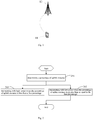
- Fig. 1 it is a structural diagram of a network system to which an embodiment of the present disclosure may be applied, which includes, as shown in Fig. 1 , a terminal 11 and a base station 12, wherein the terminal 11 may be a user equipment (UE), or another terminal equipment such as a mobile phone, a tablet personal computer, a laptop computer, a personal digital assistant (PDA), a mobile Internet device (MID), or other terminal-side devices such as a wearable device, etc.
- UE user equipment
- PDA personal digital assistant
- MID mobile Internet device
- the terminal 11 may communicate with the base station 12. For example, SDU transmission may be performed between the terminal 11 and the base station 12.
- the above base station 12 may be a base station of 5G and later versions (for example: gNB, 5G NR NB), or a base station in other communication systems, or called Node B, Evolved Node B, or other vocabulary in the field, as long as it reaches the same technical effect, the base station is not limited to specific technical vocabulary. It should be noted that, in the embodiments of the present disclosure, only a 5G base station is taken as an example, but the specific type of the base station 12 is not limited.
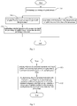
- FIG. 2 it is a flowchart of a power configuration method according to an embodiment of the present disclosure, the method is applied to a terminal, and as shown in Fig. 2 , includes the following steps:
- Step 201 determining a percentage of uplink resource.
- the above determining the percentage of uplink resource may be: determining whether the percentage of uplink resource is less than a first percentage, e.g., 50%. Of course, in the embodiment of the present disclosure, it is not limited to 50%, for example, may be 45% or 55%.
- a first percentage e.g. 50%.
- it can be directly determined for a specific slot format (such as a slot format predefined by a protocol, or a slot pre-configured by the network, etc.) that the percentage of uplink resource is less than the first percentage.
- Step 201 can also determine the resource of a certain time period or of some slot formats to determine the percentage of uplink resource thereof.
- the above first percentage may be preset by the terminal, or predefined by the protocol, or pre-configured by the network, or the like.
- Step 202 transmitting with high power when the percentage of uplink resource is less than a first percentage, wherein the high power is higher than a maximum transmitting power of a default power class.
- the percentage of uplink resource determined in Step 201 is less than the first percentage, high power may be used for transmission. This is because that, if the percentage of uplink resource is less than the above first percentage, it means that the transmission number of the terminal is relative small, and thus, the radiation SAR of the terminal is not high when high power is used for transmission, thereby preventing the radiation SAR of the terminal from being out of limit.
- the above default power class may be pre-configured by the terminal, or predefined in the protocol, or pre-configured by the network, for example, the power class 3, the maximum transmitting power of which may be 23 dBm.
- the above high power may be less than or equal to the maximum transmitting power of another power class, e.g., the power class 2, the maximum transmitting power of which may be 26 dBm.
- this power class may also be pre-configured by the terminal, or predefined in the protocol, or pre-configured by the network.
- Step 203 transmitting with low power when the percentage of uplink resource is greater than or equal to the first percentage, wherein the low power is not higher than the maximum transmitting power of the default power class.
- the percentage of uplink resource determined in Step 201 is greater than or equal to the first percentage, low power may be used for transmission. This is because that, when the percentage of uplink resource is greater than or equal to the first percentage, the radiation SAR of the terminal may be out of limit if high power is used for transmission, thereby low power is used for transmission to prevent the radiation SAR of the terminal from being out of limit.
- the above method may be applied to a 5G system, but this is not limited, and it is applicable to other communication systems as long as substantially the same function can be achieved.
- it can be applied to a 6G system, or another communication system using high power for transmission, or the like.
- the radiation SAR of a terminal can be prevented from being out of limit by: determining the percentage of uplink resource; transmitting with high power when the percentage of uplink resource is less than the first percentage, wherein the high power is higher than a maximum transmitting power of a default power class; and transmitting with low power when the percentage of uplink resource is greater than or equal to the first percentage, wherein the low power is not higher than the maximum transmitting power of the default power class.
- FIG. 3 it is a flowchart of another power configuration method according to an embodiment of the present disclosure. The method is applied to a terminal, and as shown in Fig. 3 , includes the following steps:
- Step 301 determining a percentage of uplink resource.
- Step 302 transmitting with high power when the percentage of uplink resource is less than a first percentage, wherein the high power is higher than a maximum transmitting power of a default power class.
- the above transmitting with high power may be: transmitting with high power in a case that the percentage of uplink resource is less than the first percentage; or transmitting with high power in a resource in which the percentage of uplink resource is less than the first percentage, for example, transmitting with high power in the above slot with a first slot format or a second slot format.
- the transmitting with high power when the percentage of uplink resource is less than a first percentage includes:
- the above preset slot format may be a pre-configured slot format, e.g., a slot format pre-configured by the terminal, or predefined by the protocol, or pre-configured by the network.
- the percentage of uplink symbols is less than the first portion.
- the terminal can directly determine that its percentage of uplink resource is less than the first percentage, and no further judgment is required, thereby improving the working efficiency of the terminal.
- the above preset slot format may be a subset of all slot formats prescribed by the protocol.
- the terminal may always use the above high power for transmission.
- the network can configure the terminal to work in the slot with the above preset slot format, so that the terminal can transmit with high power.
- the determining the percentage of uplink resource includes:
- the high power can be used for transmission; if the percentage of uplink resource within the certain time period is greater than or equal to the first percentage, the low power can be used for transmission.
- the terminal can directly determine that the percentage of uplink resource is less than the first percentage, and no further judgment is required, thereby improving the working efficiency of the terminal.
- the working slot is not limited to the preset slot format
- the working slot of the terminal is not limited to the preset slot format, for example, the working slot of the terminal includes slots with the preset slot format and other slot formats, or the working slot of the terminal does not include the slot with the preset slot format.
- the certain time period may be a time period configured by the network, or a time period predefined by the protocol, or a time period determined by the terminal, etc., and may be, for example, 2 ms, 2.5 ms, 5 ms, 20 ms, 40 ms, or 1 minute, or a multiple of the frame (10 ms), etc.
- the time period may also be a configuration period of the slot format set by the network, such as 5 ms, 20 ms, or a multiple of the frame (10 ms), etc.
- the terminal can dynamically determine whether the percentage of uplink resource within a certain time period is less than the first percentage. If the percentage of uplink resource in this time period is less than the first percentage, high power is used for transmission. Otherwise, low power is used for transmission, thereby preventing the radiation SAR of the terminal from being out of limit while improving the flexibility of the terminal to control the transmitting power, so as to improve the working performance of the terminal. Specifically, if the percentage of uplink resource in this time period is less than the first percentage, then high power is used for transmission in this time period, or high power is used for transmission in the next or more time periods of this time period, or, high power is used for transmission in this time period and the next or more time periods of this time period.
- Using low power to transmit may also be that: low power is used for transmission in this time period, or low power is used for transmission in the next or more time periods of this time period, or, low power is used for transmission in this time period and the next or more time periods of this time period.
- the uplink symbol may be defined in the following way:
- the flexible symbols in this slot are not used as the uplink symbol
- the flexible symbols in this slot are used as the uplink symbol according to a third percentage.
- the not using the flexible symbol as the uplink symbol may be: using the flexible symbol as a guard period (GP) symbol.
- GP guard period
- the above is a description for a case that the flexible symbols may be used as the uplink symbol.
- the above flexible symbols are flexible symbols introduced by the 5G communication system that may be used as uplink symbols, downlink symbols, or GPs that are not transmitted.
- the symbol number threshold may be pre-configured by the terminal, or predefined in the protocol, or pre-configured by the network, for example: 3 or 4 symbols. Of course, this number of symbols can also be determined specifically according to the total number of symbols included in the slot.
- the third percentage may be pre-configured by the terminal, or pre-defined in the protocol, or pre-configured by the network, for example: 50% or 45% or 55%, etc.
- these flexible symbols are assumed to be used as GPs and are not considered as uplink symbols
- the third percentage of flexible symbols in a certain slot is not an integer
- the number of uplink symbols can be determined by rounding up and rounding down.
- the above determining the percentage of uplink resource within the certain time period includes:
- the percentage of uplink resource in a certain time period by counting uplink slots and uplink symbols. Specifically, it may be achieved by counting the uplink slots in a certain time period to determine the uplink slots in the certain time period. Alternatively, it may be achieved by counting the uplink symbols in a certain time period to determine the percentage of uplink slots in the certain time period. When the percentage of uplink slots or the percentage of uplink symbols is less than the first percentage, high power is used for transmission.
- the determining the percentage of uplink resource within a certain time period may also be referred to as: identifying, counting, or judging the percentage of uplink resource in a certain time period.
- the definition of the uplink symbol may be referred to the above description, which will not be repeated here, and the same beneficial effects can be achieved.
- the above uplink slot may be defined in the following way:
- the uplink slots include: slots in which the percentage of uplink symbols exceeds a second percentage;
- the flexible symbols in this slot are not used as the uplink symbols
- the flexible symbols in this slot are used as the uplink symbols according to the third percentage.
- the uplink symbol needs to be defined in the above manner.
- the flexible symbols are used as uplink symbols according to the third percentage, which may be referred to the above description and will not be repeated here, and the same beneficial effects can be achieved.
- the terminal or the network selects a subset of slot format with the percentage of uplink slots not more than 50%, e.g., the above preset slot format.
- a high-power terminal if they are configured in this subset, high power may be used for transmission; or, when it is prescribed that they are not in this subset, high power may not be used for transmission
- the terminal or the network selects a subset of slot format with the percentage of uplink symbols not more than 50%, e.g., the above preset slot format.
- a subset of slot format with the percentage of uplink symbols not more than 50% is selected.
- high-power terminal if they are configured in this subset, high power may be used for transmission; or, when it is prescribed that they are not in this subset, high power may not be used for transmission.
- Step 303 transmitting with low power when the percentage of uplink resource is greater than or equal to the first percentage, wherein the low power is not higher than the maximum transmitting power of the default power class.
- the above transmitting with low power may be: transmitting with low power in a case that the percentage of uplink resource is greater than or equal to the first percentage; or transmitting with low power in a resource in which the percentage of uplink resource is greater than or equal to the first percentage, for example, transmitting with low power in a slot with a slot format other than the above first and second slot formats.
- the above determining the percentage of uplink resource includes:
- the high power may be used for transmission; if the percentage of uplink resource within the certain time period is greater than or equal to the first percentage, the low power may be used for transmission.
- the certain time period may be a time period configured by the network, or a time period predefined by the protocol, or a time period determined by the terminal, etc., for example, 5 ms, 20 ms, or 1 minute, or a multiple of the frame (10 ms), etc.
- the time period may also be a configuration period of the slot format set by the network, such as 5 ms, 20 ms, or a multiple of the frame (10 ms), etc.
- the terminal can dynamically determine whether the percentage of uplink resource within a certain time period is less than the first percentage. If the percentage of uplink resource in this time period is less than the first percentage, high power is used for transmission in the certain time period. Otherwise, low power is used for transmission, thereby preventing the radiation SAR of the terminal from being out of limit while improving the flexibility of the terminal to control the transmitting power, so as to improve the working performance of the terminal. Specifically, if the percentage of uplink resource in this time period is less than the first percentage, then high power is used for transmission in this time period, or high power is used for transmission in the next or more time periods of this time period, or, high power is used for transmission in this time period and the next or more time periods of this time period.
- the case of using low power to transmit may also be that: low power is used for transmission in this time period, or low power is used for transmission in the next or more time periods of this time period, or, low power is used for transmission in this time period and the next or more time periods of this time period.
- the above determining the percentage of uplink resource within a certain time period includes:
- the definitions of the uplink slot and the uplink symbol may be referred to the above description, which will not be repeated here, and the same beneficial effects can be achieved.
- the fallback measure may be as follows:
- the terminal can perform evaluation, and if the percentage of uplink resource in a certain period (or a certain time period) is higher than or equal to a certain percentage, it falls back to low-power transmission.
- the terminal detects the above preset slot format within a certain period, or the percentage of uplink resource is less than the above first percentage, it can use high power class for transmission in subsequent periods. For example, in the following implementation:
- the method may further include:
- Step 304 transmitting with the high power if a resource in which the percentage of uplink resource is less than the first percentage is detected.
- the method may further include:
- the terminal transmitting with low power if a resource in which the percentage of uplink resource is greater than or equal to the first percentage is detected. For example, if the configuration for the terminal configured by the network is not limited to a subset of slot format in which the percentage of uplink slots or uplink symbols does not exceed 50%, the terminal can perform evaluation by itself. If the percentage of uplink symbols transmitted or uplink slots transmitted is low in a certain time period (for example, not exceeding 50% actually), it is also possible to use high power for transmission after a certain period; if the percentage of uplink symbols transmitted or uplink slots transmitted is high in a certain time period (for example, higher than 50%), the terminal reduces the transmitting power by itself.
- a variety of optional implementations are added on the basis of the embodiment shown in Fig. 2 , all of them can prevent the radiation SAR of the terminal from being out of limit and can also improve the working performance of the terminal.
- FIG. 4 it is a flowchart of another power configuration method according to an embodiment of the present disclosure.
- the method is applied to a base station or a network equipment, and as shown in Fig. 4 , includes the following steps:
- Step 401 judging whether the terminal transmits with high power, wherein the high power is higher than a maximum transmitting power of a default power class;
- Step 402 if determining that the terminal transmits with high power, configuring the terminal with resources within the time in which the terminal transmits with high power, wherein the percentage of uplink resource in the resources configured to the terminal is less than the first percentage.
- the determining that the terminal transmits with high power includes:
- the terminal configuring the terminal to work in a slot with a preset slot format, wherein the percentage of uplink symbols in the preset slot format is less than the first percentage.
- the calculation method of the percentage of uplink resource includes:
- the resource configured to the terminal is determined.
- the flexible symbols in this slot are not used as the uplink symbol
- the flexible symbols in this slot are used as the uplink symbol according to a third percentage.
- the uplink slot includes: a slot in which the percentage of uplink symbols exceeds the second percentage;
- the flexible symbols in this slot are not used as the uplink symbol
- the flexible symbols in this slot are used as the uplink symbol according to a third percentage.
- the terminal 500 includes:
- a determination module 501 configured to determine a percentage of uplink resource
- a first transmission module 502 configured to transmit with high power when the percentage of uplink resource is less than a first percentage, wherein the high power is higher than a maximum transmitting power of a default power class;
- a second transmission module 503 configured to transmit with low power when the percentage of uplink resource is greater than or equal to the first percentage, wherein the low power is not higher than the maximum transmitting power of the default power class.
- the first transmission module 502 is configured to transmit with high power if the terminal works in a slot with a preset slot format, wherein a percentage of uplink symbols with the preset slot format is less than the first percentage.
- the determination module 501 is configured to determine that the percentage of uplink resource is less than the first percentage if the terminal works in a slot with the preset slot format; or
- the determination module 501 is configured to determine a percentage of uplink resource within a certain time period if a working slot of the terminal is not limited to the preset slot format.
- the determination module 501 is configured to determine a percentage of uplink resource within a certain time period.
- the determination module 501 is configured to determine a percentage of uplink slots within the certain time period.
- the determination module 501 is configured to determine a percentage of uplink symbols within the certain time period.
- the certain time period is a time period configured by a network, or a time period predefined by a protocol, or a time period determined by the terminal.
- the flexible symbols in this slot are not used as the uplink symbol
- the flexible symbols in this slot are used as the uplink symbol according to a third percentage.
- the uplink slot includes: a slot in which the percentage of uplink symbols exceeds a second percentage;
- the flexible symbols in this slot are not used as the uplink symbol
- the flexible symbols in this slot are used as the uplink symbol according to a third percentage.
- the terminal 500 further includes:
- a third transmission module 504 configured to transmit with the high power if a resource in which the percentage of uplink resource is less than the first percentage is detected.
- the terminal provided by the embodiment of the present disclosure can implement the processes implemented by the terminal in the method embodiments of Figs. 2 to 3 , and to avoid repetition, details are not described herein again.
- the terminal can prevent the radiation SAR from being out of limit.
- the base station includes:
- a judgment module 701 configured to judge whether the terminal transmits with high power, wherein the high power is higher than a maximum transmitting power of a default power class;
- a configuration module 702 configured to, if it is determined that the terminal transmits with high power, configure the terminal with resources within the time in which the terminal transmits with high power, wherein the percentage of uplink resource in the resources configured to the terminal is less than the first percentage.
- the determining that the terminal transmits with high power includes:
- the terminal configuring the terminal to work in a slot with a preset slot format, wherein the percentage of uplink symbols in the preset slot format is less than the first percentage.
- the calculation method of the percentage of uplink resource includes:
- the flexible symbols in this slot are not used as the uplink symbol
- the flexible symbols in this slot are used as the uplink symbol according to a third percentage.
- the uplink slot includes: a slot in which the percentage of uplink symbols exceeds the second percentage;
- the flexible symbols in this slot are not used as the uplink symbol
- the flexible symbols in this slot are used as the uplink symbol according to a third percentage.
- the base station provided by the embodiment of the present disclosure can implement the processes implemented by the base station in the method embodiment of Fig. 4 , and to avoid repetition, details are not described herein again.
- the base station can prevent the radiation SAR from being out of limit.
- Fig. 8 is a schematic diagram of hardware structure of an terminal according to embodiments of the present disclosure.
- the terminal 800 includes but is not limited to: a radio frequency unit 801, a network module 802, an audio output unit 803, an input unit 804, a sensor 805, a display unit 806, a user input unit 807, an interface unit 808, a storage 809, a processor 810, and a power supply 811 and other components.
- a radio frequency unit 801 includes but is not limited to: a radio frequency unit 801, a network module 802, an audio output unit 803, an input unit 804, a sensor 805, a display unit 806, a user input unit 807, an interface unit 808, a storage 809, a processor 810, and a power supply 811 and other components.
- the terminal structure shown in Fig. 8 does not constitute a limitation on the terminal, and the terminal may include more or less components than those shown in the figure, or combine certain components, or have different component arrangement.
- the terminal include, but is not limited to, a mobile phone, a tablet, a notebook computer, a palmtop computer, an on-vehi
- processor 810 is configured to determine the percentage of uplink resource
- the radio frequency unit 801 is configured to transmit with high power when the percentage of uplink resource is less than a first percentage, wherein the high power is higher than a maximum transmitting power of a default power class;
- the radio frequency unit 801 is also configured to transmit with low power when the percentage of uplink resource is greater than or equal to the first percentage, wherein the low power is not higher than the maximum transmitting power of the default power class.
- the transmission, that is performed by the processor 810, with the high power when the percentage of uplink resource is less than the first percentage includes:
- the determination, that is performed by the processor 810, the percentage of uplink resource includes:
- the determination, that is performed by the processor 810, the percentage of uplink resource includes:
- the determination, that is performed by the processor 810, the percentage of uplink resource within the certain time period includes:
- the certain time period is a time period configured by a network, or a time period predefined by a protocol, or a time period determined by the terminal.
- the flexible symbols in this slot are not used as the uplink symbol
- the flexible symbols in this slot are used as the uplink symbol according to a third percentage.
- the uplink slot includes: a slot in which the percentage of uplink symbols exceeds a second percentage;
- the flexible symbols in this slot are not used as the uplink symbol
- the flexible symbols in this slot are used as the uplink symbol according to a third percentage.
- the radio frequency unit 801 is further configured to: transmit with the high power if a resource in which the percentage of uplink resource is less than the first percentage is detected.
- the terminal can prevent the radio SAR from being out of limit.
- the radio frequency unit 801 may be used for receiving and sending signals during the information reception and transmission or a call. Specifically, the downlink data from the base station is received and given to the processor 810 for processing; further, the uplink data is sent to the base station.
- the radio frequency unit 801 includes, but is not limited to, an antenna, at least one amplifier, a transceiver, a coupler, a low noise amplifier, a duplexer, and the like.
- the radio frequency unit 801 can also communicate with the network and other devices through a wireless communication system.
- the terminal provides users with wireless broadband Internet access through the network module 802, such as helping users to send and receive emails, browse web pages, and access streaming media, etc.
- the audio output unit 803 can convert the audio data received by the radio frequency unit 801 or the network module 802 or stored in the storage 809 into audio signals and output them as sounds. Moreover, the audio output unit 803 may also provide audio output related to a specific function performed by the terminal 800 (for example, call signal reception sound, message reception sound, etc.).
- the audio output unit 803 includes a speaker, a buzzer, a receiver, and the like.
- the input unit 804 is used to receive audio or video signals.
- the input unit 804 may include a graphics processing unit (GPU) 8041 and a microphone 8042.
- the GPU 8041 processes the still pictures or image data obtained by an image capture device (such as a camera) in a video capture mode or an image capture mode.
- the processed image frames may be displayed on the display unit 806.
- the image frames processed by the GPU 8041 may be stored in the storage 809 (or other storage medium) or sent via the radio frequency unit 801 or the network module 802.
- the microphone 8042 can receive sound and can process such sound into audio data.
- the processed audio data can be converted in the telephone call mode into a format that can be sent by the radio frequency unit 801 to a mobile communication base station for output.
- the terminal 800 further includes at least one sensor 805, such as a light sensor, a motion sensor, and other sensors.
- the light sensor includes an ambient light sensor and a proximity sensor.
- the ambient light sensor can adjust the brightness of the display panel 8061 according to the brightness of the ambient light.
- the proximity sensor can close the display panel 8061 and/or the backlight when the terminal 800 is moved to the ear.
- the accelerometer sensor can detect the magnitudes of accelerations in various directions (usually, three axes), can detect the magnitude and direction of gravity when stationary, and can be used to identify terminal posture (such as horizontal and vertical screen switching, related games, magnetometer posture calibration), vibration recognition related functions (such as pedometer, percussion), etc.; the sensor 805 can also include a fingerprint sensor, a pressure sensor, an iris sensor, a molecular sensor, a gyroscope, a barometer, a hygrometer, a thermometer, an infrared sensor, etc., which will not be repeated here.
- the display unit 806 is used to display information input by the user or information provided to the user.
- the display unit 806 may include a display panel 8061, and the display panel 8061 may be configured in the form of a Liquid Crystal Display (LCD), an Organic Light-Emitting Diode (OLED), etc.
- LCD Liquid Crystal Display
- OLED Organic Light-Emitting Diode
- the user input unit 807 may be used to receive input numeric or character information, and generate key signal input related to user settings and function control of the terminal.
- the user input unit 807 includes a touch panel 8071 and other input devices 8072.
- the touch panel 8071 also known as a touch screen, can collect user's touch operation on or near it (for example, the user's operation on or near the touch panel 8071 using any suitable object or accessory, such as a finger or a stylus).
- the touch panel 8071 may include two components: a touch detection device and a touch controller.
- the touch detection device detects the user's touch orientation, and detects the signal generated by the touch operation, and transmits the signal to the touch controller; the touch controller receives touch information from the touch detection device and converts it into contact coordinates, then sends the same to the processor 810, and receives and executes the command sent by the processor 810.
- the touch panel 8071 can be implemented in various types such as resistive, capacitive, infrared, and surface acoustic wave types.
- the user input unit 807 may also include other input devices 8072.
- other input devices 8072 may include, but are not limited to, a physical keyboard, function keys (such as volume control buttons, switch buttons, etc.), a trackball, a mouse, and a joystick, which will not be repeated here.
- the touch panel 8071 may be overlaid on the display panel 8061.
- the touch panel 8071 detects a touch operation on or near it, it transmits the touch operation to the processor 8010 to determine the type of touch event, and then the processor 810 provides a corresponding visual output on the display panel 8061 according to the type of touch event.
- the touch panel 8071 and the display panel 8061 are implemented as two independent components to realize the input and output functions of the terminal, in some embodiments, the touch panel 8071 and the display panel 8061 may be integrated to implement the input and output functions of the terminal, which is not limited here.
- the interface unit 808 is an interface for connecting an external device to the terminal 800.
- the external device may include a wired or wireless headset port, an external power (or battery charger) port, a wired or wireless data port, a memory card port, a port for connecting a device having an identification module, an audio input/output (I/O) port, a video I/O port, a headphone port, etc.
- the interface unit 808 may be used to receive input from external devices (e.g., data information, power, etc.) and transmit the received input to one or more elements within the terminal 800 or may be used to transfer data between the terminal 800 and the external devices.
- the storage 809 may be used to store software programs and various data.
- the storage 809 may mainly include a program storage area and a data storage area, wherein the program storage area may store an operating system, applications required by at least one function (such as a sound playback function, an image playback function, etc.); the data storage area may store data created according to the use of a mobile phone (such as audio data, phone books, etc.), etc.
- the storage 809 may include a high-speed random access memory, and may also include a non-volatile storage, such as at least one magnetic disk storage device, a flash memory device, or other volatile solid-state storage devices.
- the processor 810 is the control center of the terminal, connects various parts of the entire terminal by using various interfaces and lines, performs various functions and processing data of the terminal by running or executing software programs and/or modules stored in the storage 809 and calling data stored in the storage 809, so as to monitor the terminal as a whole.
- the processor 810 may include one or more processing units; optionally, the processor 810 may integrate an application processor and a modem processor, where the application processor mainly processes an operating system, a user interface, and applications, etc.
- the modem processor mainly processes wireless communication. It can be understood that the foregoing modem processor may not be integrated into the processor 810.
- the terminal 800 may further include a power supply 811 (such as a battery) that supplies power to various components.
- a power supply 811 (such as a battery) that supplies power to various components.
- the power supply 811 may be logically connected to the processor 810 through a power management system, so as to implement charging, discharging, and power consumption management through the power management system.
- the terminal 800 includes some unillustrated functional modules, which will not be repeated here.
- an embodiment of the present disclosure further provides a terminal including a processor 810, a storage 809, and a computer program stored on the storage 809 and capable of running on the processor 810, the computer program implementing, when executed by the processor 810, the processes of the power configuration method embodiments as mentioned above, and achieving the same technical effects. To avoid repetition, it will not be described here again.
- the base station 900 includes: a processor 901, a transceiver 902, a storage 903 and a bus interface, wherein:
- the processor 901 is configured to judge whether the terminal transmits with high power, wherein the high power is higher than a maximum transmitting power of a default power class;
- the transceiver 902 is configured to, if it is determined that the terminal transmits with high power, configure the terminal with resources within the time in which the terminal transmits with high power, wherein the percentage of uplink resource in the resources configured to the terminal is less than the first percentage.
- the determining that the terminal transmits with high power includes:
- the terminal configuring the terminal to work in a slot with a preset slot format, wherein the percentage of uplink symbols in the preset slot format is less than the first percentage.
- the calculation method of the percentage of uplink resource includes:
- the flexible symbols in this slot are not used as the uplink symbol
- the flexible symbols in this slot are used as the uplink symbol according to a third percentage.
- the uplink slot includes: a slot in which the percentage of uplink symbols exceeds the second percentage;
- the flexible symbols in this slot are not used as the uplink symbol
- the flexible symbols in this slot are used as the uplink symbol according to a third percentage.
- the base station can prevent the radio SAR from being out of limit.
- the transceiver 902 is configured to receive and send data under the control of the processor 901, and includes at least two antenna ports.
- the bus architecture may include any number of interconnected buses and bridges, which are linked together specifically by various circuits such as one or more processors represented by the processor 901 and the storage represented by the storage 903.
- the bus architecture can also link various other circuits such as peripheral devices, voltage regulators, and power management circuits, etc., which are well known in the art, and therefore, they will not be further described herein.
- the bus interface provides interfaces.
- the transceiver 902 may be a plurality of elements, including a transmitter and a receiver, and provides units for communicating with various other devices on a transmission medium.
- the user interface may also be an interface that can externally and internally connect the required devices.
- the connected devices include but are not limited to a keypad, a display, a speaker, a microphone, a joystick, etc.
- the processor 901 is responsible for managing the bus architecture and general processing, and the storage 903 may store data used by the processor 901 when performing operations.
- an embodiment of the present disclosure further provides a base station including a processor 901, a storage 903, and a computer program stored on the storage 901 and capable of running on the processor 901, the computer program implementing, when executed by the processor 901, the processes of the power configuration method embodiments as mentioned above, and achieving the same technical effects. To avoid repetition, it will not be described here again.
- An embodiment of the present disclosure further provides a computer readable storage medium having a computer program stored thereon, the computer program implementing, when executed by a processor, the processes of the power configuration method embodiments of the above terminal side or base station side, and achieving the same technical effects.
- the computer readable storage medium may be, for example, a read-only memory (ROM), a random access memory (RAM), a magnetic disk, or an optical disk, etc.
- the methods in the above embodiments can be implemented by means of software plus a necessary general hardware platform, and of course, can also be implemented by hardware, but in many cases the former is a preferred implementation.
- the essential technical solutions of the present disclosure, or part of the technical solutions that contributes to the related art can be embodied in the form of a software product; the computer software product is stored in a storage medium (such as a ROM/RAM, a magnetic disk, or an optical disk), including several instructions used to cause a terminal (which may be a mobile phone, a computer, a server, an air conditioner, or a network device, etc.) to perform the methods described in various embodiments of the present disclosure.
- a terminal which may be a mobile phone, a computer, a server, an air conditioner, or a network device, etc.
Landscapes
- Engineering & Computer Science (AREA)
- Computer Networks & Wireless Communication (AREA)
- Signal Processing (AREA)
- Quality & Reliability (AREA)
- Mobile Radio Communication Systems (AREA)
- Electrical Discharge Machining, Electrochemical Machining, And Combined Machining (AREA)
Abstract
Description
- The present application claims the priority of Chinese Patent Application No.
201810160268.X filed on February 26th, 2018 - The present disclosure relates to the field of communications technology, and in particular to a power configuration method and a terminal.
- In the 5th Generation (5th Generation, 5G) communication systems, there are multiple power classes similar to that of the Long Term Evolution (Long Term Evolution, LTE) system, for example: power class 2. The maximum transmitting power of this power class is 26 dBm, and the power of this power class can be called high power. The maximum transmitting power of power class 3 is 23 dBm, and this power class can be called low power class or default power class. When the maximum transmitting power is higher than 23dBm, the specific absorption ratio (Specific Absorption Ratio, SAR) of a terminal may exceed the SAR limit.
- The embodiment of the present disclosure provides a power configuration method and a terminal to solve the problem that the SAR of a terminal may be out of limit.
- In a first aspect, an embodiment of the present disclosure provides a power configuration method applied to a terminal, including:
- determining a percentage of uplink resource;
- transmitting with high power when the percentage of uplink resource is less than a first percentage, wherein the high power is higher than a maximum transmitting power of a default power class;
- transmitting with low power when the percentage of uplink resource is greater than or equal to the first percentage, wherein the low power is not higher than the maximum transmitting power of the default power class.
- In a second aspect, an embodiment of the present disclosure provides a terminal including:
- a determination module configured to determine a percentage of uplink resource;
- a first transmission module configured to transmit with high power when the percentage of uplink resource is less than a first percentage, wherein the high power is higher than a maximum transmitting power of a default power class;
- a second transmission module configured to transmit with low power when the percentage of uplink resource is greater than or equal to the first percentage, wherein the low power is not higher than the maximum transmitting power of the default power class.
- In a third aspect, an embodiment of the present disclosure provides a terminal including: a storage, a processor, and a computer program stored on the storage and capable of running on the processor, the computer program implementing, when executed by the processor, the steps of the power configuration method provided by the embodiment of the present disclosure.
- In a fourth aspect, an embodiment of the present disclosure provides a computer readable storage medium having a computer program stored thereon, the computer program implementing, when executed by a processor, the steps of the power configuration method provided by the embodiment of the present disclosure.
- In the embodiments of the present disclosure, the radiation SAR of a terminal can be prevented from being out of limit by: determining a percentage of uplink resource; transmitting with high power when the percentage of uplink resource is less than a first percentage, wherein the high power is higher than a maximum transmitting power of a default power class; and transmitting with low power when the percentage of uplink resource is greater than or equal to the first percentage, wherein the low power is not higher than the maximum transmitting power of the default power class.
- In order to explain the technical solutions of the embodiments of the present disclosure more clearly, the accompanying drawings used in the description of the embodiments of the present disclosure will be described briefly below. Obviously, the drawings in the following description are only some embodiments of the present disclosure. For those of ordinary skill in the art, other drawings may be obtained based on these drawings without creative labor.
-
Fig. 1 is a structural diagram of a network system to which an embodiment of the present disclosure may be applied; -
Fig. 2 is a flowchart of a power configuration method according to an embodiment of the present disclosure; -
Fig. 3 is a flowchart of another power configuration method according to an embodiment of the present disclosure; -
Fig. 4 is a flowchart of another power configuration method according to an embodiment of the present disclosure; -
Fig. 5 is a structural diagram of a terminal according to an embodiment of the present disclosure; -
Fig. 6 is a structural diagram of another terminal according to an embodiment of the present disclosure; -
Fig. 7 is a structural diagram of a base station according to an embodiment of the present disclosure; -
Fig. 8 is a structural diagram of another terminal according to an embodiment of the present disclosure; and -
Fig. 9 is a structural diagram of another base station according to an embodiment of the present disclosure. - Hereinafter, the technical solutions in the embodiments of the present disclosure will be described clearly and thoroughly in conjunction with the drawings in the embodiments of the present disclosure. Obviously, the described embodiments are part of the embodiments of the present disclosure, but not all of the embodiments. Based on the embodiments in the present disclosure, all other embodiments obtained by a person of ordinary skill in the art without creative efforts should fall within the protection scope of the present disclosure.
- Referring to
Fig. 1 , it is a structural diagram of a network system to which an embodiment of the present disclosure may be applied, which includes, as shown inFig. 1 , aterminal 11 and abase station 12, wherein theterminal 11 may be a user equipment (UE), or another terminal equipment such as a mobile phone, a tablet personal computer, a laptop computer, a personal digital assistant (PDA), a mobile Internet device (MID), or other terminal-side devices such as a wearable device, etc. It should be noted that the specific type of theterminal 11 is not limited in the embodiments of the present disclosure. Theterminal 11 may communicate with thebase station 12. For example, SDU transmission may be performed between theterminal 11 and thebase station 12. Theabove base station 12 may be a base station of 5G and later versions (for example: gNB, 5G NR NB), or a base station in other communication systems, or called Node B, Evolved Node B, or other vocabulary in the field, as long as it reaches the same technical effect, the base station is not limited to specific technical vocabulary. It should be noted that, in the embodiments of the present disclosure, only a 5G base station is taken as an example, but the specific type of thebase station 12 is not limited. - Referring to
Fig. 2 , it is a flowchart of a power configuration method according to an embodiment of the present disclosure, the method is applied to a terminal, and as shown inFig. 2 , includes the following steps: -
Step 201, determining a percentage of uplink resource. - Wherein, the above determining the percentage of uplink resource may be: determining whether the percentage of uplink resource is less than a first percentage, e.g., 50%. Of course, in the embodiment of the present disclosure, it is not limited to 50%, for example, may be 45% or 55%. In addition, in
Step 201, it can be directly determined for a specific slot format (such as a slot format predefined by a protocol, or a slot pre-configured by the network, etc.) that the percentage of uplink resource is less than the first percentage. Of course,Step 201 can also determine the resource of a certain time period or of some slot formats to determine the percentage of uplink resource thereof. - It should be noted that, in the embodiment of the present disclosure, the above first percentage may be preset by the terminal, or predefined by the protocol, or pre-configured by the network, or the like.
-
Step 202, transmitting with high power when the percentage of uplink resource is less than a first percentage, wherein the high power is higher than a maximum transmitting power of a default power class. - If the percentage of uplink resource determined in
Step 201 is less than the first percentage, high power may be used for transmission. This is because that, if the percentage of uplink resource is less than the above first percentage, it means that the transmission number of the terminal is relative small, and thus, the radiation SAR of the terminal is not high when high power is used for transmission, thereby preventing the radiation SAR of the terminal from being out of limit. - It should be noted that, the above default power class may be pre-configured by the terminal, or predefined in the protocol, or pre-configured by the network, for example, the power class 3, the maximum transmitting power of which may be 23 dBm.
- Of course, the above high power may be less than or equal to the maximum transmitting power of another power class, e.g., the power class 2, the maximum transmitting power of which may be 26 dBm. Similarly, this power class may also be pre-configured by the terminal, or predefined in the protocol, or pre-configured by the network.
-
Step 203, transmitting with low power when the percentage of uplink resource is greater than or equal to the first percentage, wherein the low power is not higher than the maximum transmitting power of the default power class. - If the percentage of uplink resource determined in
Step 201 is greater than or equal to the first percentage, low power may be used for transmission. This is because that, when the percentage of uplink resource is greater than or equal to the first percentage, the radiation SAR of the terminal may be out of limit if high power is used for transmission, thereby low power is used for transmission to prevent the radiation SAR of the terminal from being out of limit. - Through the above steps, it can be achieved that, when the percentage of uplink resource is less than the first percentage, high power is used for transmission; otherwise, low power is used for transmission to prevent the radiation SAR of the terminal from being out of limit.
- It should be noted that the above method may be applied to a 5G system, but this is not limited, and it is applicable to other communication systems as long as substantially the same function can be achieved. For example, it can be applied to a 6G system, or another communication system using high power for transmission, or the like.
- In the embodiment of the present disclosure, the radiation SAR of a terminal can be prevented from being out of limit by: determining the percentage of uplink resource; transmitting with high power when the percentage of uplink resource is less than the first percentage, wherein the high power is higher than a maximum transmitting power of a default power class; and transmitting with low power when the percentage of uplink resource is greater than or equal to the first percentage, wherein the low power is not higher than the maximum transmitting power of the default power class.
- Referring to
Fig. 3 , it is a flowchart of another power configuration method according to an embodiment of the present disclosure. The method is applied to a terminal, and as shown inFig. 3 , includes the following steps: -
Step 301, determining a percentage of uplink resource. -
Step 302, transmitting with high power when the percentage of uplink resource is less than a first percentage, wherein the high power is higher than a maximum transmitting power of a default power class. - Wherein, the above transmitting with high power may be: transmitting with high power in a case that the percentage of uplink resource is less than the first percentage; or transmitting with high power in a resource in which the percentage of uplink resource is less than the first percentage, for example, transmitting with high power in the above slot with a first slot format or a second slot format.
- In an optional implementation, the transmitting with high power when the percentage of uplink resource is less than a first percentage includes:
- transmitting with high power if the terminal works in a slot with a preset slot format, wherein a percentage of uplink symbols with the preset slot format is less than the first percentage.
- Wherein, the above preset slot format may be a pre-configured slot format, e.g., a slot format pre-configured by the terminal, or predefined by the protocol, or pre-configured by the network. The percentage of uplink symbols is less than the first portion.
- In this way, it can be achieved that, for the above preset slot format, the terminal can directly determine that its percentage of uplink resource is less than the first percentage, and no further judgment is required, thereby improving the working efficiency of the terminal. In addition, the above preset slot format may be a subset of all slot formats prescribed by the protocol. Moreover, if the terminal always works in the above preset slot format, the terminal may always use the above high power for transmission. Alternatively, the network can configure the terminal to work in the slot with the above preset slot format, so that the terminal can transmit with high power.
- Optionally, the determining the percentage of uplink resource includes:
- determining that the percentage of uplink resource is less than the first percentage if the terminal works in a slot with the preset slot format; or
- determining a percentage of uplink resource within a certain time period if a working slot of the terminal is not limited to the preset slot format.
- Wherein, if the percentage of uplink resource within the certain time period is less than the first percentage, the high power can be used for transmission; if the percentage of uplink resource within the certain time period is greater than or equal to the first percentage, the low power can be used for transmission.
- In this implementation, if the terminal works in the slot with the preset slot format, it can directly determine that the percentage of uplink resource is less than the first percentage, and no further judgment is required, thereby improving the working efficiency of the terminal.
- Wherein, the above-mentioned "the working slot is not limited to the preset slot format" may be that the working slot of the terminal is not limited to the preset slot format, for example, the working slot of the terminal includes slots with the preset slot format and other slot formats, or the working slot of the terminal does not include the slot with the preset slot format.
- Wherein, the certain time period may be a time period configured by the network, or a time period predefined by the protocol, or a time period determined by the terminal, etc., and may be, for example, 2 ms, 2.5 ms, 5 ms, 20 ms, 40 ms, or 1 minute, or a multiple of the frame (10 ms), etc. In addition, the time period may also be a configuration period of the slot format set by the network, such as 5 ms, 20 ms, or a multiple of the frame (10 ms), etc.
- In this implementation, the terminal can dynamically determine whether the percentage of uplink resource within a certain time period is less than the first percentage. If the percentage of uplink resource in this time period is less than the first percentage, high power is used for transmission. Otherwise, low power is used for transmission, thereby preventing the radiation SAR of the terminal from being out of limit while improving the flexibility of the terminal to control the transmitting power, so as to improve the working performance of the terminal. Specifically, if the percentage of uplink resource in this time period is less than the first percentage, then high power is used for transmission in this time period, or high power is used for transmission in the next or more time periods of this time period, or, high power is used for transmission in this time period and the next or more time periods of this time period. Using low power to transmit may also be that: low power is used for transmission in this time period, or low power is used for transmission in the next or more time periods of this time period, or, low power is used for transmission in this time period and the next or more time periods of this time period.
- Optionally, in this implementation, the uplink symbol may be defined in the following way:
- for a slot in which the number of flexible symbols is less than or equal to a symbol number threshold, the flexible symbols in this slot are not used as the uplink symbol;
- for a slot in which the number of flexible symbols is greater than the symbol number threshold, the flexible symbols in this slot are used as the uplink symbol according to a third percentage.
- Wherein, the not using the flexible symbol as the uplink symbol may be: using the flexible symbol as a guard period (GP) symbol.
- It should be noted that, the above is a description for a case that the flexible symbols may be used as the uplink symbol. In the actual counting process, it is also necessary to add uplink symbols configured for uplink transmission. Wherein, the above flexible symbols are flexible symbols introduced by the 5G communication system that may be used as uplink symbols, downlink symbols, or GPs that are not transmitted. The symbol number threshold may be pre-configured by the terminal, or predefined in the protocol, or pre-configured by the network, for example: 3 or 4 symbols. Of course, this number of symbols can also be determined specifically according to the total number of symbols included in the slot. The third percentage may be pre-configured by the terminal, or pre-defined in the protocol, or pre-configured by the network, for example: 50% or 45% or 55%, etc. For example, when there are <=Y (e.g., Y=4 or 3) flexible symbols in a slot, these flexible symbols are assumed to be used as GPs and are not considered as uplink symbols; when there are >Y (e.g., Y=4) in a slot, these flexible symbols are considered as uplink symbols according to a certain percentage Z (e.g., Z=50%); for example, a slot includes 6 flexible symbols, and the above symbol number threshold is 3 or 4, then the 6 flexible symbols are regarded as uplink symbols at 50%, that is, 6 flexible symbols are counted as 3 uplink symbols. It should be noted that, when the third percentage of flexible symbols in a certain slot is not an integer, the number of uplink symbols can be determined by rounding up and rounding down.
- In this implementation, since the flexible symbols are counted flexibly, the situation that the radiation SAR of the terminal is out of limit caused by the flexible symbols introduced by the 5G communication system is avoided.
- Optionally, in the above implementation, the above determining the percentage of uplink resource within the certain time period includes:
- determining a percentage of uplink slots within the certain time period; or
- determining a percentage of uplink symbols within the certain time period.
- In this way, it is possible to determine the percentage of uplink resource in a certain time period by counting uplink slots and uplink symbols. Specifically, it may be achieved by counting the uplink slots in a certain time period to determine the uplink slots in the certain time period. Alternatively, it may be achieved by counting the uplink symbols in a certain time period to determine the percentage of uplink slots in the certain time period. When the percentage of uplink slots or the percentage of uplink symbols is less than the first percentage, high power is used for transmission. Of course, in the embodiments of the present disclosure, the determining the percentage of uplink resource within a certain time period may also be referred to as: identifying, counting, or judging the percentage of uplink resource in a certain time period.
- Wherein, during determining the percentage of uplink resource, the definition of the uplink symbol may be referred to the above description, which will not be repeated here, and the same beneficial effects can be achieved.
- The above uplink slot may be defined in the following way:
- the uplink slots include: slots in which the percentage of uplink symbols exceeds a second percentage;
- wherein, for a slot in which the number of flexible symbols is less than or equal to the symbol number threshold, the flexible symbols in this slot are not used as the uplink symbols;
- for a slot in which the number of flexible symbols is greater than the symbol number threshold, the flexible symbols in this slot are used as the uplink symbols according to the third percentage.
- In this way, the uplink slot may be defined as a slot in which the percentage of uplink symbols exceeds the second percentage, wherein the second percentage may be pre-configured by the terminal, or predefined in the protocol, or pre-configured by the network, for example: 70% or 65% or 75%, etc.; for example, a slot in which the percentage of uplink symbols exceeds a threshold X (e.g., X=70%) is regarded as the uplink slot.
- Wherein, during defining the uplink slot, the uplink symbol needs to be defined in the above manner. Wherein, the flexible symbols are used as uplink symbols according to the third percentage, which may be referred to the above description and will not be repeated here, and the same beneficial effects can be achieved.
- For example, the terminal or the network selects a subset of slot format with the percentage of uplink slots not more than 50%, e.g., the above preset slot format. It is prescribed that the uplink slot is defined as the follows: a slot with the percentage of uplink symbols exceeding a threshold X (e.g., X=70%) is regarded as a uplink slot; wherein, the counting method of flexible symbols is: when there are <=Y (e.g., Y=4 or 3) flexible symbols in a slot, these flexible symbols are assumed to be used as GPs and are not counted as uplink symbols; when there are >Y (e.g., Y=4 or 3) flexible symbols in a slot, these flexible symbols are counted as uplink symbols at a percentage Z (e.g., Z=50%). For a high-power terminal, if they are configured in this subset, high power may be used for transmission; or, when it is prescribed that they are not in this subset, high power may not be used for transmission.
- For another example, the terminal or the network selects a subset of slot format with the percentage of uplink symbols not more than 50%, e.g., the above preset slot format. Wherein the counting method of flexible symbols is: when there are <=Y (e.g., Y=4 or 3) flexible symbols in a slot, these flexible symbols are assumed to be used as GPs and are not counted as UL symbols; when there are >Y (e.g., Y=4 or 3) flexible symbols, these flexible symbols are counted as uplink symbols at a certain percentage Z (e.g., Z=50%). In this way, according to the above criterion, a subset of slot format with the percentage of uplink symbols not more than 50% is selected. For a high-power terminal, if they are configured in this subset, high power may be used for transmission; or, when it is prescribed that they are not in this subset, high power may not be used for transmission.
-
Step 303, transmitting with low power when the percentage of uplink resource is greater than or equal to the first percentage, wherein the low power is not higher than the maximum transmitting power of the default power class. - Wherein, the above transmitting with low power may be: transmitting with low power in a case that the percentage of uplink resource is greater than or equal to the first percentage; or transmitting with low power in a resource in which the percentage of uplink resource is greater than or equal to the first percentage, for example, transmitting with low power in a slot with a slot format other than the above first and second slot formats.
- In another optional implementation, the above determining the percentage of uplink resource includes:
- determining the percentage of uplink resource within a certain time period.
- Wherein, if the percentage of uplink resource within the certain time period is less than the first percentage, the high power may be used for transmission; if the percentage of uplink resource within the certain time period is greater than or equal to the first percentage, the low power may be used for transmission.
- Wherein, the certain time period may be a time period configured by the network, or a time period predefined by the protocol, or a time period determined by the terminal, etc., for example, 5 ms, 20 ms, or 1 minute, or a multiple of the frame (10 ms), etc. In addition, the time period may also be a configuration period of the slot format set by the network, such as 5 ms, 20 ms, or a multiple of the frame (10 ms), etc.
- In this implementation, the terminal can dynamically determine whether the percentage of uplink resource within a certain time period is less than the first percentage. If the percentage of uplink resource in this time period is less than the first percentage, high power is used for transmission in the certain time period. Otherwise, low power is used for transmission, thereby preventing the radiation SAR of the terminal from being out of limit while improving the flexibility of the terminal to control the transmitting power, so as to improve the working performance of the terminal. Specifically, if the percentage of uplink resource in this time period is less than the first percentage, then high power is used for transmission in this time period, or high power is used for transmission in the next or more time periods of this time period, or, high power is used for transmission in this time period and the next or more time periods of this time period. The case of using low power to transmit may also be that: low power is used for transmission in this time period, or low power is used for transmission in the next or more time periods of this time period, or, low power is used for transmission in this time period and the next or more time periods of this time period.
- Wherein, for the above determining the percentage of uplink resource within a certain time period, reference may be made to the description of the above implementation. For example, the above determining the percentage of uplink resource within a certain time period includes:
- determining a percentage of uplink slots within the certain time period; or
- determining a percentage of uplink symbols within the certain time period.
- Wherein, during determining the percentage of uplink resource, the definitions of the uplink slot and the uplink symbol may be referred to the above description, which will not be repeated here, and the same beneficial effects can be achieved.
- In this implementation, it can be achieved that, if the percentage of uplink slots or the percentage of uplink symbols within a certain time period is less than the above first percentage, high power is used for transmission; otherwise, low power is used for transmission.
- It should be noted that, the above using the low power for transmission when the percentage of uplink resource is greater than or equal to the first percentage may also be referred to as: the terminal adopting a fallback measure when the percentage of uplink resource is greater than or equal to the first percentage. Wherein the fallback measure may be as follows:
- if the network configuration does not meet the above preset slot format, or the percentage of uplink resource is not less than the above first percentage, the terminal can perform evaluation, and if the percentage of uplink resource in a certain period (or a certain time period) is higher than or equal to a certain percentage, it falls back to low-power transmission. Of course, if the terminal detects the above preset slot format within a certain period, or the percentage of uplink resource is less than the above first percentage, it can use high power class for transmission in subsequent periods. For example, in the following implementation:
- As shown in
Fig. 3 , after the transmitting with the low power when the percentage of uplink resource is greater than or equal to the first percentage, the method may further include: -
Step 304, transmitting with the high power if a resource in which the percentage of uplink resource is less than the first percentage is detected. - In this implementation, it can be achieved that, after the terminal transmits with low power, if a resource in which the percentage of uplink resource is less than the first percentage is detected, high power is used for transmission, thereby achieving the flexibility of the transmitting power of the terminal, so as to improve the working performance of the terminal
- Of course, after transmitting with high power when the percentage of uplink resource is less than the first percentage, the method may further include:
- transmitting with low power if a resource in which the percentage of uplink resource is greater than or equal to the first percentage is detected. For example, if the configuration for the terminal configured by the network is not limited to a subset of slot format in which the percentage of uplink slots or uplink symbols does not exceed 50%, the terminal can perform evaluation by itself. If the percentage of uplink symbols transmitted or uplink slots transmitted is low in a certain time period (for example, not exceeding 50% actually), it is also possible to use high power for transmission after a certain period; if the percentage of uplink symbols transmitted or uplink slots transmitted is high in a certain time period (for example, higher than 50%), the terminal reduces the transmitting power by itself.
- In this embodiment, a variety of optional implementations are added on the basis of the embodiment shown in
Fig. 2 , all of them can prevent the radiation SAR of the terminal from being out of limit and can also improve the working performance of the terminal. - Referring to
Fig. 4 , it is a flowchart of another power configuration method according to an embodiment of the present disclosure. The method is applied to a base station or a network equipment, and as shown inFig. 4 , includes the following steps: -
Step 401, judging whether the terminal transmits with high power, wherein the high power is higher than a maximum transmitting power of a default power class; -
Step 402, if determining that the terminal transmits with high power, configuring the terminal with resources within the time in which the terminal transmits with high power, wherein the percentage of uplink resource in the resources configured to the terminal is less than the first percentage. - Optionally, the determining that the terminal transmits with high power includes:
- configuring the terminal to work in a slot with a preset slot format, wherein the percentage of uplink symbols in the preset slot format is less than the first percentage.
- Optionally, the calculation method of the percentage of uplink resource includes:
- determining a percentage of uplink slots in a time period in which the terminal transmits with high power; or
- determining a percentage of uplink symbols within the time in which the terminal transmits with high power.
- With the above calculation method, the resource configured to the terminal is determined.
- Optionally, for a slot in which the number of flexible symbols is less than or equal to a symbol number threshold, the flexible symbols in this slot are not used as the uplink symbol;
- for a slot in which the number of flexible symbols is greater than the symbol number threshold, the flexible symbols in this slot are used as the uplink symbol according to a third percentage.
- Optionally, the uplink slot includes: a slot in which the percentage of uplink symbols exceeds the second percentage;
- wherein, for a slot in which the number of flexible symbols is less than or equal to the symbol number threshold, the flexible symbols in this slot are not used as the uplink symbol;
- for a slot in which the number of flexible symbols is greater than the symbol number threshold, the flexible symbols in this slot are used as the uplink symbol according to a third percentage.
- It should be noted that, for the specific implementations of this embodiment, which is an implementation of a base station corresponding to the embodiments shown in
Figs. 2 and3 , reference may be made to the related descriptions of the embodiments shown inFigs. 2 and3 , and the same beneficial effects are achieved. In order to avoid repetition, these will not be described again here. - Referring to
Fig. 5 , it is a structural diagram of a terminal according to an embodiment of the present disclosure. As shown inFig. 5 , the terminal 500 includes: - a
determination module 501 configured to determine a percentage of uplink resource; - a
first transmission module 502 configured to transmit with high power when the percentage of uplink resource is less than a first percentage, wherein the high power is higher than a maximum transmitting power of a default power class; - a
second transmission module 503 configured to transmit with low power when the percentage of uplink resource is greater than or equal to the first percentage, wherein the low power is not higher than the maximum transmitting power of the default power class. - Optionally, the
first transmission module 502 is configured to transmit with high power if the terminal works in a slot with a preset slot format, wherein a percentage of uplink symbols with the preset slot format is less than the first percentage. - Optionally, the
determination module 501 is configured to determine that the percentage of uplink resource is less than the first percentage if the terminal works in a slot with the preset slot format; or - the
determination module 501 is configured to determine a percentage of uplink resource within a certain time period if a working slot of the terminal is not limited to the preset slot format. - Optionally, the
determination module 501 is configured to determine a percentage of uplink resource within a certain time period. - Optionally, the
determination module 501 is configured to determine a percentage of uplink slots within the certain time period; or - Optionally, the
determination module 501 is configured to determine a percentage of uplink symbols within the certain time period. - Optionally, the certain time period is a time period configured by a network, or a time period predefined by a protocol, or a time period determined by the terminal.
- Optionally, for a slot in which a number of flexible symbols is less than or equal to a symbol number threshold, the flexible symbols in this slot are not used as the uplink symbol;
- for a slot in which the number of flexible symbols is greater than the symbol number threshold, the flexible symbols in this slot are used as the uplink symbol according to a third percentage.
- Optionally, the uplink slot includes: a slot in which the percentage of uplink symbols exceeds a second percentage;
- wherein, for a slot in which a number of flexible symbols is less than or equal to a symbol number threshold, the flexible symbols in this slot are not used as the uplink symbol;
- for a slot in which the number of flexible symbols is greater than the symbol number threshold, the flexible symbols in this slot are used as the uplink symbol according to a third percentage.
- Optionally, as shown in
Fig. 6 , the terminal 500 further includes: - a
third transmission module 504 configured to transmit with the high power if a resource in which the percentage of uplink resource is less than the first percentage is detected. - The terminal provided by the embodiment of the present disclosure can implement the processes implemented by the terminal in the method embodiments of
Figs. 2 to 3 , and to avoid repetition, details are not described herein again. The terminal can prevent the radiation SAR from being out of limit. - Referring to
Fig. 7 , it is a structural diagram of a base station according to an embodiment of the present disclosure. As shown inFig. 7 , the base station includes: - a
judgment module 701 configured to judge whether the terminal transmits with high power, wherein the high power is higher than a maximum transmitting power of a default power class; - a
configuration module 702 configured to, if it is determined that the terminal transmits with high power, configure the terminal with resources within the time in which the terminal transmits with high power, wherein the percentage of uplink resource in the resources configured to the terminal is less than the first percentage. - Optionally, the determining that the terminal transmits with high power includes:
- configuring the terminal to work in a slot with a preset slot format, wherein the percentage of uplink symbols in the preset slot format is less than the first percentage.
- Optionally, the calculation method of the percentage of uplink resource includes:
- determining a percentage of uplink slots in a time period in which the terminal transmits with high power; or
- determining a percentage of uplink symbols within the time in which the terminal transmits with high power.
- Optionally, for a slot in which the number of flexible symbols is less than or equal to a symbol number threshold, the flexible symbols in this slot are not used as the uplink symbol;
- for a slot in which the number of flexible symbols is greater than the symbol number threshold, the flexible symbols in this slot are used as the uplink symbol according to a third percentage.
- Optionally, the uplink slot includes: a slot in which the percentage of uplink symbols exceeds the second percentage;
- wherein, for a slot in which the number of flexible symbols is less than or equal to the symbol number threshold, the flexible symbols in this slot are not used as the uplink symbol;
- for a slot in which the number of flexible symbols is greater than the symbol number threshold, the flexible symbols in this slot are used as the uplink symbol according to a third percentage.
- The base station provided by the embodiment of the present disclosure can implement the processes implemented by the base station in the method embodiment of
Fig. 4 , and to avoid repetition, details are not described herein again. The base station can prevent the radiation SAR from being out of limit. -
Fig. 8 is a schematic diagram of hardware structure of an terminal according to embodiments of the present disclosure. - The terminal 800 includes but is not limited to: a
radio frequency unit 801, anetwork module 802, anaudio output unit 803, aninput unit 804, asensor 805, adisplay unit 806, auser input unit 807, aninterface unit 808, astorage 809, aprocessor 810, and apower supply 811 and other components. Those skilled in the art can understand that the terminal structure shown inFig. 8 does not constitute a limitation on the terminal, and the terminal may include more or less components than those shown in the figure, or combine certain components, or have different component arrangement. In the embodiments of the present disclosure, the terminal include, but is not limited to, a mobile phone, a tablet, a notebook computer, a palmtop computer, an on-vehicle terminal, a wearable device, and a pedometer, etc. - Wherein the
processor 810 is configured to determine the percentage of uplink resource; - the
radio frequency unit 801 is configured to transmit with high power when the percentage of uplink resource is less than a first percentage, wherein the high power is higher than a maximum transmitting power of a default power class; - the
radio frequency unit 801 is also configured to transmit with low power when the percentage of uplink resource is greater than or equal to the first percentage, wherein the low power is not higher than the maximum transmitting power of the default power class. - Optionally, the transmission, that is performed by the
processor 810, with the high power when the percentage of uplink resource is less than the first percentage includes: - transmitting with the high power if the terminal works in a slot with a preset slot format, wherein a percentage of uplink symbols with the preset slot format is less than the first percentage.
- Optionally, the determination, that is performed by the
processor 810, the percentage of uplink resource includes: - determining that the percentage of uplink resource is less than the first percentage if the terminal works in a slot with the preset slot format; or
- determining a percentage of uplink resource within a certain time period if a working slot of the terminal is not limited to the preset slot format.
- Optionally, the determination, that is performed by the
processor 810, the percentage of uplink resource includes: - determining a percentage of uplink resource within a certain time period.
- Optionally, the determination, that is performed by the
processor 810, the percentage of uplink resource within the certain time period includes: - determining a percentage of uplink slots within the certain time period; or
- determining a percentage of uplink symbols within the certain time period.
- Optionally, the certain time period is a time period configured by a network, or a time period predefined by a protocol, or a time period determined by the terminal.
- Optionally, for a slot in which a number of flexible symbols is less than or equal to a symbol number threshold, the flexible symbols in this slot are not used as the uplink symbol;
- for a slot in which the number of flexible symbols is greater than the symbol number threshold, the flexible symbols in this slot are used as the uplink symbol according to a third percentage.
- Optionally, the uplink slot includes: a slot in which the percentage of uplink symbols exceeds a second percentage;
- wherein, for a slot in which a number of flexible symbols is less than or equal to a symbol number threshold, the flexible symbols in this slot are not used as the uplink symbol;
- for a slot in which the number of flexible symbols is greater than the symbol number threshold, the flexible symbols in this slot are used as the uplink symbol according to a third percentage.
- Optionally, after the transmission with the low power when the percentage of uplink resource is greater than or equal to the first percentage, the
radio frequency unit 801 is further configured to: transmit with the high power if a resource in which the percentage of uplink resource is less than the first percentage is detected. - The terminal can prevent the radio SAR from being out of limit.
- It should be understood that, in the embodiment of the present disclosure, the
radio frequency unit 801 may be used for receiving and sending signals during the information reception and transmission or a call. Specifically, the downlink data from the base station is received and given to theprocessor 810 for processing; further, the uplink data is sent to the base station. Generally, theradio frequency unit 801 includes, but is not limited to, an antenna, at least one amplifier, a transceiver, a coupler, a low noise amplifier, a duplexer, and the like. In addition, theradio frequency unit 801 can also communicate with the network and other devices through a wireless communication system. - The terminal provides users with wireless broadband Internet access through the
network module 802, such as helping users to send and receive emails, browse web pages, and access streaming media, etc. - The
audio output unit 803 can convert the audio data received by theradio frequency unit 801 or thenetwork module 802 or stored in thestorage 809 into audio signals and output them as sounds. Moreover, theaudio output unit 803 may also provide audio output related to a specific function performed by the terminal 800 (for example, call signal reception sound, message reception sound, etc.). Theaudio output unit 803 includes a speaker, a buzzer, a receiver, and the like. - The
input unit 804 is used to receive audio or video signals. Theinput unit 804 may include a graphics processing unit (GPU) 8041 and amicrophone 8042. TheGPU 8041 processes the still pictures or image data obtained by an image capture device (such as a camera) in a video capture mode or an image capture mode. The processed image frames may be displayed on thedisplay unit 806. The image frames processed by theGPU 8041 may be stored in the storage 809 (or other storage medium) or sent via theradio frequency unit 801 or thenetwork module 802. Themicrophone 8042 can receive sound and can process such sound into audio data. The processed audio data can be converted in the telephone call mode into a format that can be sent by theradio frequency unit 801 to a mobile communication base station for output. - The terminal 800 further includes at least one
sensor 805, such as a light sensor, a motion sensor, and other sensors. Specifically, the light sensor includes an ambient light sensor and a proximity sensor. The ambient light sensor can adjust the brightness of thedisplay panel 8061 according to the brightness of the ambient light. The proximity sensor can close thedisplay panel 8061 and/or the backlight when the terminal 800 is moved to the ear. As a kind of motion sensor, the accelerometer sensor can detect the magnitudes of accelerations in various directions (usually, three axes), can detect the magnitude and direction of gravity when stationary, and can be used to identify terminal posture (such as horizontal and vertical screen switching, related games, magnetometer posture calibration), vibration recognition related functions (such as pedometer, percussion), etc.; thesensor 805 can also include a fingerprint sensor, a pressure sensor, an iris sensor, a molecular sensor, a gyroscope, a barometer, a hygrometer, a thermometer, an infrared sensor, etc., which will not be repeated here. - The
display unit 806 is used to display information input by the user or information provided to the user. Thedisplay unit 806 may include adisplay panel 8061, and thedisplay panel 8061 may be configured in the form of a Liquid Crystal Display (LCD), an Organic Light-Emitting Diode (OLED), etc. - The
user input unit 807 may be used to receive input numeric or character information, and generate key signal input related to user settings and function control of the terminal. Specifically, theuser input unit 807 includes atouch panel 8071 andother input devices 8072. Thetouch panel 8071, also known as a touch screen, can collect user's touch operation on or near it (for example, the user's operation on or near thetouch panel 8071 using any suitable object or accessory, such as a finger or a stylus). Thetouch panel 8071 may include two components: a touch detection device and a touch controller. Among them, the touch detection device detects the user's touch orientation, and detects the signal generated by the touch operation, and transmits the signal to the touch controller; the touch controller receives touch information from the touch detection device and converts it into contact coordinates, then sends the same to theprocessor 810, and receives and executes the command sent by theprocessor 810. In addition, thetouch panel 8071 can be implemented in various types such as resistive, capacitive, infrared, and surface acoustic wave types. In addition to thetouch panel 8071, theuser input unit 807 may also includeother input devices 8072. Specifically,other input devices 8072 may include, but are not limited to, a physical keyboard, function keys (such as volume control buttons, switch buttons, etc.), a trackball, a mouse, and a joystick, which will not be repeated here. - Further, the
touch panel 8071 may be overlaid on thedisplay panel 8061. When thetouch panel 8071 detects a touch operation on or near it, it transmits the touch operation to the processor 8010 to determine the type of touch event, and then theprocessor 810 provides a corresponding visual output on thedisplay panel 8061 according to the type of touch event. Although inFig. 8 , thetouch panel 8071 and thedisplay panel 8061 are implemented as two independent components to realize the input and output functions of the terminal, in some embodiments, thetouch panel 8071 and thedisplay panel 8061 may be integrated to implement the input and output functions of the terminal, which is not limited here. - The
interface unit 808 is an interface for connecting an external device to the terminal 800. For example, the external device may include a wired or wireless headset port, an external power (or battery charger) port, a wired or wireless data port, a memory card port, a port for connecting a device having an identification module, an audio input/output (I/O) port, a video I/O port, a headphone port, etc. Theinterface unit 808 may be used to receive input from external devices (e.g., data information, power, etc.) and transmit the received input to one or more elements within the terminal 800 or may be used to transfer data between the terminal 800 and the external devices. - The
storage 809 may be used to store software programs and various data. Thestorage 809 may mainly include a program storage area and a data storage area, wherein the program storage area may store an operating system, applications required by at least one function (such as a sound playback function, an image playback function, etc.); the data storage area may store data created according to the use of a mobile phone (such as audio data, phone books, etc.), etc. In addition, thestorage 809 may include a high-speed random access memory, and may also include a non-volatile storage, such as at least one magnetic disk storage device, a flash memory device, or other volatile solid-state storage devices. - The
processor 810 is the control center of the terminal, connects various parts of the entire terminal by using various interfaces and lines, performs various functions and processing data of the terminal by running or executing software programs and/or modules stored in thestorage 809 and calling data stored in thestorage 809, so as to monitor the terminal as a whole. Theprocessor 810 may include one or more processing units; optionally, theprocessor 810 may integrate an application processor and a modem processor, where the application processor mainly processes an operating system, a user interface, and applications, etc. The modem processor mainly processes wireless communication. It can be understood that the foregoing modem processor may not be integrated into theprocessor 810. - The terminal 800 may further include a power supply 811 (such as a battery) that supplies power to various components. optionally, the
power supply 811 may be logically connected to theprocessor 810 through a power management system, so as to implement charging, discharging, and power consumption management through the power management system. - In addition, the terminal 800 includes some unillustrated functional modules, which will not be repeated here.
- Optionally, an embodiment of the present disclosure further provides a terminal including a
processor 810, astorage 809, and a computer program stored on thestorage 809 and capable of running on theprocessor 810, the computer program implementing, when executed by theprocessor 810, the processes of the power configuration method embodiments as mentioned above, and achieving the same technical effects. To avoid repetition, it will not be described here again. - Referring to
Fig. 9 , it is a structural diagram of another base station according to an embodiment of the present disclosure.as shown inFig. 9 , thebase station 900 includes: aprocessor 901, atransceiver 902, astorage 903 and a bus interface, wherein: - the
processor 901 is configured to judge whether the terminal transmits with high power, wherein the high power is higher than a maximum transmitting power of a default power class; - the
transceiver 902 is configured to, if it is determined that the terminal transmits with high power, configure the terminal with resources within the time in which the terminal transmits with high power, wherein the percentage of uplink resource in the resources configured to the terminal is less than the first percentage. - Optionally, the determining that the terminal transmits with high power includes:
- configuring the terminal to work in a slot with a preset slot format, wherein the percentage of uplink symbols in the preset slot format is less than the first percentage.
- Optionally, the calculation method of the percentage of uplink resource includes:
- determining a percentage of uplink slots in a time period in which the terminal transmits with high power; or
- determining a percentage of uplink symbols within the time in which the terminal transmits with high power.
- Optionally, for a slot in which the number of flexible symbols is less than or equal to a symbol number threshold, the flexible symbols in this slot are not used as the uplink symbol;
- for a slot in which the number of flexible symbols is greater than the symbol number threshold, the flexible symbols in this slot are used as the uplink symbol according to a third percentage.
- Optionally, the uplink slot includes: a slot in which the percentage of uplink symbols exceeds the second percentage;
- wherein, for a slot in which the number of flexible symbols is less than or equal to the symbol number threshold, the flexible symbols in this slot are not used as the uplink symbol;
- for a slot in which the number of flexible symbols is greater than the symbol number threshold, the flexible symbols in this slot are used as the uplink symbol according to a third percentage.
- The base station can prevent the radio SAR from being out of limit.
- Wherein, the
transceiver 902 is configured to receive and send data under the control of theprocessor 901, and includes at least two antenna ports. - In
Fig. 9 , the bus architecture may include any number of interconnected buses and bridges, which are linked together specifically by various circuits such as one or more processors represented by theprocessor 901 and the storage represented by thestorage 903. The bus architecture can also link various other circuits such as peripheral devices, voltage regulators, and power management circuits, etc., which are well known in the art, and therefore, they will not be further described herein. The bus interface provides interfaces. Thetransceiver 902 may be a plurality of elements, including a transmitter and a receiver, and provides units for communicating with various other devices on a transmission medium. For different user equipments, the user interface may also be an interface that can externally and internally connect the required devices. The connected devices include but are not limited to a keypad, a display, a speaker, a microphone, a joystick, etc. - The
processor 901 is responsible for managing the bus architecture and general processing, and thestorage 903 may store data used by theprocessor 901 when performing operations. - Optionally, an embodiment of the present disclosure further provides a base station including a
processor 901, astorage 903, and a computer program stored on thestorage 901 and capable of running on theprocessor 901, the computer program implementing, when executed by theprocessor 901, the processes of the power configuration method embodiments as mentioned above, and achieving the same technical effects. To avoid repetition, it will not be described here again. - An embodiment of the present disclosure further provides a computer readable storage medium having a computer program stored thereon, the computer program implementing, when executed by a processor, the processes of the power configuration method embodiments of the above terminal side or base station side, and achieving the same technical effects. To avoid repetition, it will not be described here again. Wherein, the computer readable storage medium may be, for example, a read-only memory (ROM), a random access memory (RAM), a magnetic disk, or an optical disk, etc.
- It should be noted that, herein the terms "comprising", "including" or any other variant thereof are intended to cover non-exclusive inclusion, so that a process, method, article, or device that includes a series of elements includes not only those elements, but also those that are not explicitly listed, or further includes elements inherent to such process, method, article or device. Without more restrictions, the element defined by the sentence "comprising a..." does not exclude that there are other identical elements in the process, method, article, or device that includes the element.
- With the description of the above embodiments, those skilled in the art can clearly understand that the methods in the above embodiments can be implemented by means of software plus a necessary general hardware platform, and of course, can also be implemented by hardware, but in many cases the former is a preferred implementation. Based on such an understanding, the essential technical solutions of the present disclosure, or part of the technical solutions that contributes to the related art, can be embodied in the form of a software product; the computer software product is stored in a storage medium (such as a ROM/RAM, a magnetic disk, or an optical disk), including several instructions used to cause a terminal (which may be a mobile phone, a computer, a server, an air conditioner, or a network device, etc.) to perform the methods described in various embodiments of the present disclosure.
- The embodiments of the present disclosure have been described above with reference to the drawings, but the present disclosure is not limited to the above specific embodiments. The above specific embodiments are merely schematic, not restrictive. Under the inspiration of the present disclosure, many forms can be made by those skilled in the art without departing from the purpose of the present disclosure and the scope protected by the claims, all of which fall within the protective scope of the present disclosure.
Claims (22)
- A power configuration method applied to a terminal, comprising:determining a percentage of uplink resource;transmitting with high power when the percentage of uplink resource is less than a first percentage, wherein the high power is higher than a maximum transmitting power of a default power class;transmitting with low power when the percentage of uplink resource is greater than or equal to the first percentage, wherein the low power is not higher than the maximum transmitting power of the default power class.
- The method according to claim 1, wherein the transmitting with the high power when the percentage of uplink resource is less than the first percentage comprises:
transmitting with the high power if the terminal works in a slot with a preset slot format, wherein a percentage of uplink symbols with the preset slot format is less than the first percentage. - The method according to claim 2, wherein the determining the percentage of uplink resource comprises:determining that the percentage of uplink resource is less than the first percentage if the terminal works in a slot with the preset slot format; ordetermining a percentage of uplink resource within a certain time period if a working slot of the terminal is not limited to the preset slot format.
- The method according to claim 1, wherein the determining the percentage of uplink resource comprises:determining a percentage of uplink resource within a certain time period.
- The method according to claim 4, wherein the determining the percentage of uplink resource within the certain time period comprises:determining a percentage of uplink slots within the certain time period; ordetermining a percentage of uplink symbols within the certain time period.
- The method according to claim 4, wherein the certain time period is a time period configured by a network, or a time period predefined by a protocol, or a time period determined by the terminal.
- The method according to claim 2 or 5, wherein, for a slot in which a number of flexible symbols is less than or equal to a symbol number threshold, the flexible symbols in this slot are not used as the uplink symbol;
for a slot in which the number of flexible symbols is greater than the symbol number threshold, the flexible symbols in this slot are used as the uplink symbol according to a third percentage. - The method according to claim 5, wherein the uplink slot comprises: a slot in which the percentage of uplink symbols exceeds a second percentage;
wherein, for a slot in which a number of flexible symbols is less than or equal to a symbol number threshold, the flexible symbols in this slot are not used as the uplink symbol;
for a slot in which the number of flexible symbols is greater than the symbol number threshold, the flexible symbols in this slot are used as the uplink symbol according to a third percentage. - The method according to any one of claims 1 to 6, wherein, after the transmitting with the low power when the percentage of uplink resource is greater than or equal to the first percentage, the method further comprises:
transmitting with the high power if a resource in which the percentage of uplink resource is less than the first percentage is detected. - The method according to claim 1, wherein the determining the percentage of uplink resource comprises:
determining a percentage of uplink symbols in a time period in which the terminal transmits with the high power as the percentage of uplink resource. - A terminal, comprising:a determination module configured to determine a percentage of uplink resource;a first transmission module configured to transmit with high power when the percentage of uplink resource is less than a first percentage, wherein the high power is higher than a maximum transmitting power of a default power class;a second transmission module configured to transmit with low power when the percentage of uplink resource is greater than or equal to the first percentage, wherein the low power is not higher than the maximum transmitting power of the default power class.
- The terminal according to claim 11, wherein the first transmission module is configured to transmit with high power if the terminal works in a slot with a preset slot format, wherein a percentage of uplink symbols with the preset slot format is less than the first percentage.
- The terminal according to claim 12, wherein the determination module is configured to determine that the percentage of uplink resource is less than the first percentage if the terminal works in a slot with the preset slot format; or
the determination module is configured to determine a percentage of uplink resource within a certain time period if a working slot of the terminal is not limited to the preset slot format. - The terminal according to claim 11, wherein the determination module is configured to determine a percentage of uplink resource within a certain time period.
- The terminal according to claim 14, wherein,
the determination module is configured to determine a percentage of uplink slots within the certain time period; or
the determination module is configured to determine a percentage of uplink symbols within the certain time period. - The terminal according to claim 14, wherein the certain time period is a time period configured by a network, or a time period predefined by a protocol, or a time period determined by the terminal.
- The terminal according to claim 12 or 15, wherein for a slot in which a number of flexible symbols are less than or equal to a symbol number threshold, the flexible symbols in this slot are not used as the uplink symbol;
for a slot in which the number of flexible symbols are greater than the symbol number threshold, the flexible symbols in this slot are used as the uplink symbol according to a third percentage. - The terminal according to claim 15, wherein, the uplink slot comprises: a slot in which the percentage of uplink symbols exceeds a second percentage;
wherein, for a slot in which a number of flexible symbols is less than or equal to a symbol number threshold, the flexible symbols in this slot are not used as the uplink symbol;
for a slot in which the number of flexible symbols is greater than the symbol number threshold, the flexible symbols in this slot are used as the uplink symbol according to a third percentage. - The terminal according to any of claims 11 to 16, further comprising:
a third transmission module configured to transmit with the high power if a resource in which the percentage of uplink resource is less than the first percentage is detected. - The terminal according to claim 11, wherein the determination module determining the percentage of uplink resource comprises:
the determination module determines a percentage of uplink symbols in a time period in which the terminal transmits with the high power as the percentage of uplink resource. - A terminal comprising: a storage, a processor, and a computer program stored on the storage and capable of running on the processor, the computer program implementing, when executed by the processor, the steps of the power configuration method according to any of claims 1 to 10.
- A computer readable storage medium having a computer program stored thereon, the computer program implementing, when executed by a processor, the steps of the power configuration method according to any of claims 1 to 10.
Applications Claiming Priority (2)
| Application Number | Priority Date | Filing Date | Title |
|---|---|---|---|
| CN201810160268.XA CN110198560B (en) | 2018-02-26 | 2018-02-26 | Power configuration method and terminal |
| PCT/CN2019/075544 WO2019161764A1 (en) | 2018-02-26 | 2019-02-20 | Power configuration method and terminal |
Publications (3)
| Publication Number | Publication Date |
|---|---|
| EP3761724A1 true EP3761724A1 (en) | 2021-01-06 |
| EP3761724A4 EP3761724A4 (en) | 2021-04-21 |
| EP3761724B1 EP3761724B1 (en) | 2023-07-19 |
Family
ID=67686996
Family Applications (1)
| Application Number | Title | Priority Date | Filing Date |
|---|---|---|---|
| EP19756852.0A Active EP3761724B1 (en) | 2018-02-26 | 2019-02-20 | Power configuration method and terminal |
Country Status (7)
| Country | Link |
|---|---|
| US (1) | US11375497B2 (en) |
| EP (1) | EP3761724B1 (en) |
| CN (1) | CN110198560B (en) |
| ES (1) | ES2952932T3 (en) |
| HU (1) | HUE063612T2 (en) |
| PT (1) | PT3761724T (en) |
| WO (1) | WO2019161764A1 (en) |
Cited By (1)
| Publication number | Priority date | Publication date | Assignee | Title |
|---|---|---|---|---|
| EP4546893A4 (en) * | 2022-06-21 | 2026-04-22 | Ntt Docomo Inc | END DEVICE, RADIO COMMUNICATION METHOD AND BASE STATION |
Families Citing this family (4)
| Publication number | Priority date | Publication date | Assignee | Title |
|---|---|---|---|---|
| WO2019214966A1 (en) * | 2018-05-11 | 2019-11-14 | Nokia Technologies Oy | Broadcast operation with bi-directional subframe slots in multibeam deployment |
| EP3796009B1 (en) * | 2019-09-18 | 2024-03-06 | Rohde & Schwarz GmbH & Co. KG | Sar measurement for a combined 5g and lte rf device |
| CN113163435B (en) * | 2020-01-22 | 2022-11-22 | 华为技术有限公司 | Method for determining back-off power and method for adjusting transmission power |
| US12588003B2 (en) * | 2023-02-25 | 2026-03-24 | Verizon Patent And Licensing Inc. | Systems and methods for dynamic radio channel configuration in a radio access network |
Family Cites Families (10)
| Publication number | Priority date | Publication date | Assignee | Title |
|---|---|---|---|---|
| US8718694B2 (en) * | 2007-12-07 | 2014-05-06 | Interdigital Patent Holdings, Inc. | Method and apparatus of signaling and procedure to support uplink power level determination |
| WO2009075548A1 (en) * | 2007-12-12 | 2009-06-18 | Lg Electronics Inc. | A method for controlling uplink power control considering multiplexing rate/ratio |
| KR20110081954A (en) * | 2008-09-22 | 2011-07-15 | 가부시키가이샤 엔티티 도코모 | Mobile station and radio base station |
| US8965441B1 (en) | 2010-01-22 | 2015-02-24 | Amazon Technologies, Inc. | Reducing wireless interference with transmit power level management |
| KR101196811B1 (en) * | 2011-03-16 | 2012-11-06 | 서울대학교산학협력단 | Method And Apparatus For Dynamic Inter-Cell Interference Avoidance |
| CN102869080B (en) * | 2011-12-22 | 2015-03-25 | 电信科学技术研究院 | Method and device for controlling uplink power |
| US9144028B2 (en) * | 2012-12-31 | 2015-09-22 | Motorola Solutions, Inc. | Method and apparatus for uplink power control in a wireless communication system |
| US9949220B2 (en) | 2015-03-27 | 2018-04-17 | Qualcomm Incorporated | Uplink scheduling with power control command in an FDD half-duplex network |
| US20170265148A1 (en) | 2016-03-09 | 2017-09-14 | Qualcomm Incorporated | Power control based on sar and/or harq |
| WO2019227444A1 (en) | 2018-05-31 | 2019-12-05 | 北京小米移动软件有限公司 | Method and device for controlling uplink transmission power, base station and user equipment |
-
2018
- 2018-02-26 CN CN201810160268.XA patent/CN110198560B/en active Active
-
2019
- 2019-02-20 WO PCT/CN2019/075544 patent/WO2019161764A1/en not_active Ceased
- 2019-02-20 US US16/976,034 patent/US11375497B2/en active Active
- 2019-02-20 HU HUE19756852A patent/HUE063612T2/en unknown
- 2019-02-20 EP EP19756852.0A patent/EP3761724B1/en active Active
- 2019-02-20 PT PT197568520T patent/PT3761724T/en unknown
- 2019-02-20 ES ES19756852T patent/ES2952932T3/en active Active
Cited By (1)
| Publication number | Priority date | Publication date | Assignee | Title |
|---|---|---|---|---|
| EP4546893A4 (en) * | 2022-06-21 | 2026-04-22 | Ntt Docomo Inc | END DEVICE, RADIO COMMUNICATION METHOD AND BASE STATION |
Also Published As
| Publication number | Publication date |
|---|---|
| CN110198560A (en) | 2019-09-03 |
| US11375497B2 (en) | 2022-06-28 |
| EP3761724A4 (en) | 2021-04-21 |
| EP3761724B1 (en) | 2023-07-19 |
| HUE063612T2 (en) | 2024-01-28 |
| US20200413386A1 (en) | 2020-12-31 |
| CN110198560B (en) | 2020-11-13 |
| WO2019161764A1 (en) | 2019-08-29 |
| ES2952932T3 (en) | 2023-11-07 |
| PT3761724T (en) | 2023-08-18 |
Similar Documents
| Publication | Publication Date | Title |
|---|---|---|
| EP3998713B1 (en) | Transmitting antenna switching method and terminal device | |
| US11375497B2 (en) | Power configuration method and terminal | |
| EP3876645B1 (en) | Uplink transmission method, user equipment and network-side device | |
| US11936474B2 (en) | Transmission antenna switching method and terminal device | |
| CN109819450B (en) | Signal receiving method, device and terminal | |
| CN112584374B (en) | Capability parameter determination method, uplink scheduling method, terminal and network side equipment | |
| CN110149185B (en) | Method for determining CSI resource type, terminal and network side equipment | |
| EP3713279B1 (en) | Adjacent cell rrm measurement control method, mobile communication terminal, and network side device | |
| US12101754B2 (en) | Interference processing method, terminal, and network-side device | |
| CN109739394B (en) | SAR value processing method and mobile terminal | |
| WO2021027713A1 (en) | Uplink transmission method, uplink transmission control method, and related device | |
| EP3996304A1 (en) | Uplink transmission discarding method, uplink transmission discarding configuration method and related device | |
| WO2019184761A1 (en) | Indication method for measurement result, terminal, and base station | |
| US12137381B2 (en) | Random access method and terminal | |
| CN110012529B (en) | A gain mode switching method and mobile terminal | |
| US20200389887A1 (en) | Spatial relationship determination method, terminal and base station | |
| US11523442B2 (en) | Random access resource selection method and terminal device | |
| CN113099542B (en) | Parameter reporting method, uplink scheduling method, device and medium | |
| EP3860201B1 (en) | Power headroom reporting method and terminal device | |
| CN109947617B (en) | Method, terminal and readable storage medium for monitoring display content of application interface | |
| US11570724B2 (en) | Method for PH calculation and terminal | |
| CN109828652B (en) | Control method of power consumption mode and terminal equipment | |
| CN108646928A (en) | A character input method, terminal equipment | |
| EP3993487A1 (en) | Handling method and apparatus | |
| HK40064732A (en) | Interference processing method, terminal and network-side device |
Legal Events
| Date | Code | Title | Description |
|---|---|---|---|
| STAA | Information on the status of an ep patent application or granted ep patent |
Free format text: STATUS: THE INTERNATIONAL PUBLICATION HAS BEEN MADE |
|
| PUAI | Public reference made under article 153(3) epc to a published international application that has entered the european phase |
Free format text: ORIGINAL CODE: 0009012 |
|
| STAA | Information on the status of an ep patent application or granted ep patent |
Free format text: STATUS: REQUEST FOR EXAMINATION WAS MADE |
|
| 17P | Request for examination filed |
Effective date: 20200907 |
|
| AK | Designated contracting states |
Kind code of ref document: A1 Designated state(s): AL AT BE BG CH CY CZ DE DK EE ES FI FR GB GR HR HU IE IS IT LI LT LU LV MC MK MT NL NO PL PT RO RS SE SI SK SM TR |
|
| AX | Request for extension of the european patent |
Extension state: BA ME |
|
| REG | Reference to a national code |
Ref country code: DE Ref legal event code: R079 Free format text: PREVIOUS MAIN CLASS: H04W0052180000 Ipc: H04W0052140000 Ref country code: DE Ref legal event code: R079 Ref document number: 602019033083 Country of ref document: DE Free format text: PREVIOUS MAIN CLASS: H04W0052180000 Ipc: H04W0052140000 |
|
| A4 | Supplementary search report drawn up and despatched |
Effective date: 20210319 |
|
| RIC1 | Information provided on ipc code assigned before grant |
Ipc: H04W 52/14 20090101AFI20210315BHEP Ipc: H04W 52/24 20090101ALI20210315BHEP Ipc: H04W 52/26 20090101ALI20210315BHEP Ipc: H04W 52/36 20090101ALI20210315BHEP Ipc: H04W 88/02 20090101ALI20210315BHEP |
|
| DAV | Request for validation of the european patent (deleted) | ||
| DAX | Request for extension of the european patent (deleted) | ||
| GRAP | Despatch of communication of intention to grant a patent |
Free format text: ORIGINAL CODE: EPIDOSNIGR1 |
|
| STAA | Information on the status of an ep patent application or granted ep patent |
Free format text: STATUS: GRANT OF PATENT IS INTENDED |
|
| INTG | Intention to grant announced |
Effective date: 20230215 |
|
| GRAS | Grant fee paid |
Free format text: ORIGINAL CODE: EPIDOSNIGR3 |
|
| GRAA | (expected) grant |
Free format text: ORIGINAL CODE: 0009210 |
|
| STAA | Information on the status of an ep patent application or granted ep patent |
Free format text: STATUS: THE PATENT HAS BEEN GRANTED |
|
| AK | Designated contracting states |
Kind code of ref document: B1 Designated state(s): AL AT BE BG CH CY CZ DE DK EE ES FI FR GB GR HR HU IE IS IT LI LT LU LV MC MK MT NL NO PL PT RO RS SE SI SK SM TR |
|
| REG | Reference to a national code |
Ref country code: GB Ref legal event code: FG4D |
|
| REG | Reference to a national code |
Ref country code: CH Ref legal event code: EP |
|
| REG | Reference to a national code |
Ref country code: DE Ref legal event code: R096 Ref document number: 602019033083 Country of ref document: DE |
|
| REG | Reference to a national code |
Ref country code: IE Ref legal event code: FG4D |
|
| REG | Reference to a national code |
Ref country code: PT Ref legal event code: SC4A Ref document number: 3761724 Country of ref document: PT Date of ref document: 20230818 Kind code of ref document: T Free format text: AVAILABILITY OF NATIONAL TRANSLATION Effective date: 20230810 |
|
| REG | Reference to a national code |
Ref country code: NL Ref legal event code: FP |
|
| REG | Reference to a national code |
Ref country code: SK Ref legal event code: T3 Ref document number: E 41959 Country of ref document: SK |
|
| REG | Reference to a national code |
Ref country code: LT Ref legal event code: MG9D |
|
| REG | Reference to a national code |
Ref country code: AT Ref legal event code: MK05 Ref document number: 1590733 Country of ref document: AT Kind code of ref document: T Effective date: 20230719 |
|
| PG25 | Lapsed in a contracting state [announced via postgrant information from national office to epo] |
Ref country code: GR Free format text: LAPSE BECAUSE OF FAILURE TO SUBMIT A TRANSLATION OF THE DESCRIPTION OR TO PAY THE FEE WITHIN THE PRESCRIBED TIME-LIMIT Effective date: 20231020 |
|
| PG25 | Lapsed in a contracting state [announced via postgrant information from national office to epo] |
Ref country code: IS Free format text: LAPSE BECAUSE OF FAILURE TO SUBMIT A TRANSLATION OF THE DESCRIPTION OR TO PAY THE FEE WITHIN THE PRESCRIBED TIME-LIMIT Effective date: 20231119 |
|
| REG | Reference to a national code |
Ref country code: HU Ref legal event code: AG4A Ref document number: E063612 Country of ref document: HU |
|
| PG25 | Lapsed in a contracting state [announced via postgrant information from national office to epo] |
Ref country code: SE Free format text: LAPSE BECAUSE OF FAILURE TO SUBMIT A TRANSLATION OF THE DESCRIPTION OR TO PAY THE FEE WITHIN THE PRESCRIBED TIME-LIMIT Effective date: 20230719 Ref country code: RS Free format text: LAPSE BECAUSE OF FAILURE TO SUBMIT A TRANSLATION OF THE DESCRIPTION OR TO PAY THE FEE WITHIN THE PRESCRIBED TIME-LIMIT Effective date: 20230719 Ref country code: NO Free format text: LAPSE BECAUSE OF FAILURE TO SUBMIT A TRANSLATION OF THE DESCRIPTION OR TO PAY THE FEE WITHIN THE PRESCRIBED TIME-LIMIT Effective date: 20231019 Ref country code: LV Free format text: LAPSE BECAUSE OF FAILURE TO SUBMIT A TRANSLATION OF THE DESCRIPTION OR TO PAY THE FEE WITHIN THE PRESCRIBED TIME-LIMIT Effective date: 20230719 Ref country code: LT Free format text: LAPSE BECAUSE OF FAILURE TO SUBMIT A TRANSLATION OF THE DESCRIPTION OR TO PAY THE FEE WITHIN THE PRESCRIBED TIME-LIMIT Effective date: 20230719 Ref country code: IS Free format text: LAPSE BECAUSE OF FAILURE TO SUBMIT A TRANSLATION OF THE DESCRIPTION OR TO PAY THE FEE WITHIN THE PRESCRIBED TIME-LIMIT Effective date: 20231119 Ref country code: HR Free format text: LAPSE BECAUSE OF FAILURE TO SUBMIT A TRANSLATION OF THE DESCRIPTION OR TO PAY THE FEE WITHIN THE PRESCRIBED TIME-LIMIT Effective date: 20230719 Ref country code: GR Free format text: LAPSE BECAUSE OF FAILURE TO SUBMIT A TRANSLATION OF THE DESCRIPTION OR TO PAY THE FEE WITHIN THE PRESCRIBED TIME-LIMIT Effective date: 20231020 Ref country code: FI Free format text: LAPSE BECAUSE OF FAILURE TO SUBMIT A TRANSLATION OF THE DESCRIPTION OR TO PAY THE FEE WITHIN THE PRESCRIBED TIME-LIMIT Effective date: 20230719 Ref country code: AT Free format text: LAPSE BECAUSE OF FAILURE TO SUBMIT A TRANSLATION OF THE DESCRIPTION OR TO PAY THE FEE WITHIN THE PRESCRIBED TIME-LIMIT Effective date: 20230719 |
|
| PG25 | Lapsed in a contracting state [announced via postgrant information from national office to epo] |
Ref country code: PL Free format text: LAPSE BECAUSE OF FAILURE TO SUBMIT A TRANSLATION OF THE DESCRIPTION OR TO PAY THE FEE WITHIN THE PRESCRIBED TIME-LIMIT Effective date: 20230719 |
|
| REG | Reference to a national code |
Ref country code: DE Ref legal event code: R097 Ref document number: 602019033083 Country of ref document: DE |
|
| PG25 | Lapsed in a contracting state [announced via postgrant information from national office to epo] |
Ref country code: SM Free format text: LAPSE BECAUSE OF FAILURE TO SUBMIT A TRANSLATION OF THE DESCRIPTION OR TO PAY THE FEE WITHIN THE PRESCRIBED TIME-LIMIT Effective date: 20230719 Ref country code: RO Free format text: LAPSE BECAUSE OF FAILURE TO SUBMIT A TRANSLATION OF THE DESCRIPTION OR TO PAY THE FEE WITHIN THE PRESCRIBED TIME-LIMIT Effective date: 20230719 Ref country code: EE Free format text: LAPSE BECAUSE OF FAILURE TO SUBMIT A TRANSLATION OF THE DESCRIPTION OR TO PAY THE FEE WITHIN THE PRESCRIBED TIME-LIMIT Effective date: 20230719 Ref country code: DK Free format text: LAPSE BECAUSE OF FAILURE TO SUBMIT A TRANSLATION OF THE DESCRIPTION OR TO PAY THE FEE WITHIN THE PRESCRIBED TIME-LIMIT Effective date: 20230719 Ref country code: CZ Free format text: LAPSE BECAUSE OF FAILURE TO SUBMIT A TRANSLATION OF THE DESCRIPTION OR TO PAY THE FEE WITHIN THE PRESCRIBED TIME-LIMIT Effective date: 20230719 |
|
| PLBE | No opposition filed within time limit |
Free format text: ORIGINAL CODE: 0009261 |
|
| STAA | Information on the status of an ep patent application or granted ep patent |
Free format text: STATUS: NO OPPOSITION FILED WITHIN TIME LIMIT |
|
| 26N | No opposition filed |
Effective date: 20240422 |
|
| PG25 | Lapsed in a contracting state [announced via postgrant information from national office to epo] |
Ref country code: SI Free format text: LAPSE BECAUSE OF FAILURE TO SUBMIT A TRANSLATION OF THE DESCRIPTION OR TO PAY THE FEE WITHIN THE PRESCRIBED TIME-LIMIT Effective date: 20230719 |
|
| PG25 | Lapsed in a contracting state [announced via postgrant information from national office to epo] |
Ref country code: MC Free format text: LAPSE BECAUSE OF FAILURE TO SUBMIT A TRANSLATION OF THE DESCRIPTION OR TO PAY THE FEE WITHIN THE PRESCRIBED TIME-LIMIT Effective date: 20230719 |
|
| PG25 | Lapsed in a contracting state [announced via postgrant information from national office to epo] |
Ref country code: LU Free format text: LAPSE BECAUSE OF NON-PAYMENT OF DUE FEES Effective date: 20240220 |
|
| PG25 | Lapsed in a contracting state [announced via postgrant information from national office to epo] |
Ref country code: LU Free format text: LAPSE BECAUSE OF NON-PAYMENT OF DUE FEES Effective date: 20240220 |
|
| PG25 | Lapsed in a contracting state [announced via postgrant information from national office to epo] |
Ref country code: BG Free format text: LAPSE BECAUSE OF FAILURE TO SUBMIT A TRANSLATION OF THE DESCRIPTION OR TO PAY THE FEE WITHIN THE PRESCRIBED TIME-LIMIT Effective date: 20230719 |
|
| PG25 | Lapsed in a contracting state [announced via postgrant information from national office to epo] |
Ref country code: BG Free format text: LAPSE BECAUSE OF FAILURE TO SUBMIT A TRANSLATION OF THE DESCRIPTION OR TO PAY THE FEE WITHIN THE PRESCRIBED TIME-LIMIT Effective date: 20230719 |
|
| REG | Reference to a national code |
Ref country code: BE Ref legal event code: MM Effective date: 20240229 |
|
| PG25 | Lapsed in a contracting state [announced via postgrant information from national office to epo] |
Ref country code: BE Free format text: LAPSE BECAUSE OF NON-PAYMENT OF DUE FEES Effective date: 20240229 |
|
| PG25 | Lapsed in a contracting state [announced via postgrant information from national office to epo] |
Ref country code: BE Free format text: LAPSE BECAUSE OF NON-PAYMENT OF DUE FEES Effective date: 20240229 |
|
| PG25 | Lapsed in a contracting state [announced via postgrant information from national office to epo] |
Ref country code: CY Free format text: LAPSE BECAUSE OF FAILURE TO SUBMIT A TRANSLATION OF THE DESCRIPTION OR TO PAY THE FEE WITHIN THE PRESCRIBED TIME-LIMIT; INVALID AB INITIO Effective date: 20190220 |
|
| PG25 | Lapsed in a contracting state [announced via postgrant information from national office to epo] |
Ref country code: TR Free format text: LAPSE BECAUSE OF FAILURE TO SUBMIT A TRANSLATION OF THE DESCRIPTION OR TO PAY THE FEE WITHIN THE PRESCRIBED TIME-LIMIT Effective date: 20230719 |
|
| PGFP | Annual fee paid to national office [announced via postgrant information from national office to epo] |
Ref country code: FR Payment date: 20251231 Year of fee payment: 8 |
|
| PGFP | Annual fee paid to national office [announced via postgrant information from national office to epo] |
Ref country code: NL Payment date: 20260106 Year of fee payment: 8 |
|
| REG | Reference to a national code |
Ref country code: CH Ref legal event code: U11 Free format text: ST27 STATUS EVENT CODE: U-0-0-U10-U11 (AS PROVIDED BY THE NATIONAL OFFICE) Effective date: 20260301 |
|
| PGFP | Annual fee paid to national office [announced via postgrant information from national office to epo] |
Ref country code: HU Payment date: 20260130 Year of fee payment: 8 |
|
| PGFP | Annual fee paid to national office [announced via postgrant information from national office to epo] |
Ref country code: GB Payment date: 20260106 Year of fee payment: 8 |
|
| PGFP | Annual fee paid to national office [announced via postgrant information from national office to epo] |
Ref country code: ES Payment date: 20260311 Year of fee payment: 8 |
|
| PGFP | Annual fee paid to national office [announced via postgrant information from national office to epo] |
Ref country code: DE Payment date: 20251230 Year of fee payment: 8 Ref country code: IE Payment date: 20260102 Year of fee payment: 8 |
|
| PGFP | Annual fee paid to national office [announced via postgrant information from national office to epo] |
Ref country code: IT Payment date: 20260122 Year of fee payment: 8 |
|
| PGFP | Annual fee paid to national office [announced via postgrant information from national office to epo] |
Ref country code: CH Payment date: 20260301 Year of fee payment: 8 Ref country code: PT Payment date: 20260216 Year of fee payment: 8 |
|
| PGFP | Annual fee paid to national office [announced via postgrant information from national office to epo] |
Ref country code: SK Payment date: 20260113 Year of fee payment: 8 |