EP3761671B1 - Hearing device with adaptive sub-band beamforming and related method - Google Patents
Hearing device with adaptive sub-band beamforming and related method Download PDFInfo
- Publication number
- EP3761671B1 EP3761671B1 EP20170594.4A EP20170594A EP3761671B1 EP 3761671 B1 EP3761671 B1 EP 3761671B1 EP 20170594 A EP20170594 A EP 20170594A EP 3761671 B1 EP3761671 B1 EP 3761671B1
- Authority
- EP
- European Patent Office
- Prior art keywords
- bandpass
- beamform
- signal
- contralateral
- hearing device
- Prior art date
- Legal status (The legal status is an assumption and is not a legal conclusion. Google has not performed a legal analysis and makes no representation as to the accuracy of the status listed.)
- Active
Links
- 238000000034 method Methods 0.000 title claims description 34
- 230000003044 adaptive effect Effects 0.000 title claims description 20
- 238000001914 filtration Methods 0.000 claims description 27
- 238000012545 processing Methods 0.000 claims description 16
- 238000004891 communication Methods 0.000 claims description 6
- 230000008901 benefit Effects 0.000 description 8
- 210000005069 ears Anatomy 0.000 description 4
- 230000006870 function Effects 0.000 description 4
- 238000013461 design Methods 0.000 description 3
- 230000000694 effects Effects 0.000 description 3
- 230000007246 mechanism Effects 0.000 description 3
- 230000009467 reduction Effects 0.000 description 3
- 230000006978 adaptation Effects 0.000 description 2
- 238000012986 modification Methods 0.000 description 2
- 230000004048 modification Effects 0.000 description 2
- 230000002093 peripheral effect Effects 0.000 description 2
- 230000008569 process Effects 0.000 description 2
- 239000013598 vector Substances 0.000 description 2
- 206010011878 Deafness Diseases 0.000 description 1
- 238000004458 analytical method Methods 0.000 description 1
- 230000002146 bilateral effect Effects 0.000 description 1
- 230000005540 biological transmission Effects 0.000 description 1
- 210000004556 brain Anatomy 0.000 description 1
- 238000004364 calculation method Methods 0.000 description 1
- 230000001413 cellular effect Effects 0.000 description 1
- 230000006835 compression Effects 0.000 description 1
- 238000007906 compression Methods 0.000 description 1
- 230000001419 dependent effect Effects 0.000 description 1
- 238000010586 diagram Methods 0.000 description 1
- 230000009977 dual effect Effects 0.000 description 1
- 238000005516 engineering process Methods 0.000 description 1
- 230000010370 hearing loss Effects 0.000 description 1
- 231100000888 hearing loss Toxicity 0.000 description 1
- 208000016354 hearing loss disease Diseases 0.000 description 1
- 230000003993 interaction Effects 0.000 description 1
- 238000012423 maintenance Methods 0.000 description 1
- 230000000873 masking effect Effects 0.000 description 1
- 238000012544 monitoring process Methods 0.000 description 1
- 230000001537 neural effect Effects 0.000 description 1
- 238000005070 sampling Methods 0.000 description 1
- 230000010332 selective attention Effects 0.000 description 1
- 230000001629 suppression Effects 0.000 description 1
Images


Classifications
-
- H—ELECTRICITY
- H04—ELECTRIC COMMUNICATION TECHNIQUE
- H04R—LOUDSPEAKERS, MICROPHONES, GRAMOPHONE PICK-UPS OR LIKE ACOUSTIC ELECTROMECHANICAL TRANSDUCERS; DEAF-AID SETS; PUBLIC ADDRESS SYSTEMS
- H04R25/00—Deaf-aid sets, i.e. electro-acoustic or electro-mechanical hearing aids; Electric tinnitus maskers providing an auditory perception
- H04R25/55—Deaf-aid sets, i.e. electro-acoustic or electro-mechanical hearing aids; Electric tinnitus maskers providing an auditory perception using an external connection, either wireless or wired
- H04R25/552—Binaural
-
- H—ELECTRICITY
- H04—ELECTRIC COMMUNICATION TECHNIQUE
- H04R—LOUDSPEAKERS, MICROPHONES, GRAMOPHONE PICK-UPS OR LIKE ACOUSTIC ELECTROMECHANICAL TRANSDUCERS; DEAF-AID SETS; PUBLIC ADDRESS SYSTEMS
- H04R25/00—Deaf-aid sets, i.e. electro-acoustic or electro-mechanical hearing aids; Electric tinnitus maskers providing an auditory perception
- H04R25/40—Arrangements for obtaining a desired directivity characteristic
- H04R25/407—Circuits for combining signals of a plurality of transducers
-
- H—ELECTRICITY
- H04—ELECTRIC COMMUNICATION TECHNIQUE
- H04R—LOUDSPEAKERS, MICROPHONES, GRAMOPHONE PICK-UPS OR LIKE ACOUSTIC ELECTROMECHANICAL TRANSDUCERS; DEAF-AID SETS; PUBLIC ADDRESS SYSTEMS
- H04R25/00—Deaf-aid sets, i.e. electro-acoustic or electro-mechanical hearing aids; Electric tinnitus maskers providing an auditory perception
- H04R25/55—Deaf-aid sets, i.e. electro-acoustic or electro-mechanical hearing aids; Electric tinnitus maskers providing an auditory perception using an external connection, either wireless or wired
- H04R25/554—Deaf-aid sets, i.e. electro-acoustic or electro-mechanical hearing aids; Electric tinnitus maskers providing an auditory perception using an external connection, either wireless or wired using a wireless connection, e.g. between microphone and amplifier or using Tcoils
-
- H—ELECTRICITY
- H04—ELECTRIC COMMUNICATION TECHNIQUE
- H04R—LOUDSPEAKERS, MICROPHONES, GRAMOPHONE PICK-UPS OR LIKE ACOUSTIC ELECTROMECHANICAL TRANSDUCERS; DEAF-AID SETS; PUBLIC ADDRESS SYSTEMS
- H04R25/00—Deaf-aid sets, i.e. electro-acoustic or electro-mechanical hearing aids; Electric tinnitus maskers providing an auditory perception
- H04R25/55—Deaf-aid sets, i.e. electro-acoustic or electro-mechanical hearing aids; Electric tinnitus maskers providing an auditory perception using an external connection, either wireless or wired
- H04R25/558—Remote control, e.g. of amplification, frequency
-
- H—ELECTRICITY
- H04—ELECTRIC COMMUNICATION TECHNIQUE
- H04R—LOUDSPEAKERS, MICROPHONES, GRAMOPHONE PICK-UPS OR LIKE ACOUSTIC ELECTROMECHANICAL TRANSDUCERS; DEAF-AID SETS; PUBLIC ADDRESS SYSTEMS
- H04R2225/00—Details of deaf aids covered by H04R25/00, not provided for in any of its subgroups
- H04R2225/43—Signal processing in hearing aids to enhance the speech intelligibility
-
- H—ELECTRICITY
- H04—ELECTRIC COMMUNICATION TECHNIQUE
- H04R—LOUDSPEAKERS, MICROPHONES, GRAMOPHONE PICK-UPS OR LIKE ACOUSTIC ELECTROMECHANICAL TRANSDUCERS; DEAF-AID SETS; PUBLIC ADDRESS SYSTEMS
- H04R2430/00—Signal processing covered by H04R, not provided for in its groups
- H04R2430/20—Processing of the output signals of the acoustic transducers of an array for obtaining a desired directivity characteristic
Definitions
- the present disclosure relates to a hearing device with adaptive binaural auditory steering and a method of operating a hearing device in a binaural hearing system.
- acoustic filtering due to the head shadow effect and the binaural neural interaction plays an important part to enhance the speech of the focused talker while suppressing other interference.
- the brain also forms another sound image from two ears to monitor the other acoustic sources, which are suppressed by the binaural beamforming effects.
- US 2015/0289065 A1 relates to a binaural hearing assistance system comprising binaural noise reduction.
- the user can input the location of the target sound source, e.g. with a remote control or cellular phone, and a noise reduction system operates based on the inputted location.
- EP 3 101 919 relates to a method of operating a hearing system and a peer to peer system hearing system comprising first and second hearing aid systems, each being configured to be worn by first and second persons and adapted to exchange audio data between them.
- US 2013/259239 A1 discloses a hearing aid performing double beamforming steps.
- One frequency domain monaural beamformer (fig. 2 element 26) is fed by a dual microphone setup from the hearing device.
- a monaural beamform signal is received from a contralateral hearing device ( fig. 2 , element E1) and converted to the frequency domain.
- the two frequency domain monaural beamform signals are then provided to a frequency domain binaural beamformer ( fig. 2 , element 28).
- the signals from the acoustic sources are spatially filtered by an extra stage, i.e. hearing aids, especially when the hearing aids apply higher order beamforming technologies to enhance the directivities.
- a hearing device for a binaural hearing system comprising the hearing device and a contralateral hearing device.
- the hearing device comprises a transceiver module for communication with a contralateral hearing device of the binaural hearing system, the transceiver module configured configured to obtain a contralateral bandpass beamform signal from the contralateral hearing device; a set of microphones comprising a first microphone for provision of a first microphone input signal, and a second microphone for provision of a second microphone input signal; a first beamforming module, connected to the set of microphones, for provision of a first beamform signal based on the first microphone input signal and the second microphone input signal; a filter bank connected to the first beamforming module for filtering the first beamform signal into a plurality of first sub-band beamform signals including a first bandpass beamform signal; a second beamforming module connected to the filter bank and connected directly to the transceiver module for receiving the contralateral beamform signal, the second beamforming module comprising a bandpass beamformer for provision of a second bandpass beamform signal
- a binaural hearing system comprising a hearing device and a contralateral hearing device, wherein the hearing device is a hearing device as disclosed herein.
- the contralateral hearing device may be a hearing device as disclosed herein.
- a method of operating a hearing device in a binaural hearing system comprising the hearing device and a contralateral hearing device, the hearing device comprising a transceiver module, a first microphone, a second microphone, a first beamforming module, a filter bank, and a second beamforming module, the second beamforming module directly connected to the transceiver module for receiving a contralateral bandpass beamform signal, is disclosed, the method comprising obtaining, with the transceiver module, the contralateral bandpass beamform signal from the contralateral hearing device; obtaining a first microphone input signal with the first microphone and a second microphone input signal with the second microphone; providing, with the first beamforming module, a first beamform signal based on the first microphone input signal and the second microphone input signal; filtering, with the filter bank, the first beamform signal into a plurality of first sub-band beamform signals to provide a first bandpass beamform signal; providing, with the second beamforming module, a second bandpass beamform signal based on the first bandpass beamform signal and the contralateral band
- the present devices and methods provide improved binaural auditory steering strategy (BASS) for integrating acoustic, auditory processing and selective listening mechanisms.
- BASS binaural auditory steering strategy
- the present devices and methods form a highly focused directional microphone beam for the attended talker and at the same time forms a receiving pattern similar to omni microphone characteristic for other talkers on the side.
- the present disclosure integrates acoustical filtering, peripheral processing and central listening level to provide an improved hearing device solution.
- the present disclosure provides an optimized beamforming to accommodate both selective/targeted listening and situational awareness.
- the bandpass beamformer comprises a bandpass beamform controller and a first multiplier, wherein the bandpass beamformer is configured to determine a first bandpass coefficient for the first bandpass beamform signal based on the first bandpass beamform signal and the contralateral bandpass beamform signal, and to apply the first bandpass coefficient in the first multiplier.
- the bandpass beamformer is configured to determine the first bandpass coefficient for the first bandpass beamform signal by solving a minimization problem based on expected power values of the first bandpass beamform signal and the contralateral bandpass beamform signal.
- the bandpass beamformer is configured to determine the first bandpass coefficient for the first bandpass beamform signal by solving a minimization problem based on an expected mean square value of a linear combination of the first bandpass beamform signal and the contralateral bandpass beamform signal.
- the bandpass beamformer comprises a contralateral multiplier
- the bandpass beamform controller is configured to determine a contralateral bandpass coefficient for the contralateral bandpass beamform signal based on the first bandpass beamform signal and the contralateral bandpass beamform signal, and to apply the contralateral bandpass coefficient in the contralateral multiplier.
- the bandpass beamform controller is configured to determine the contralateral bandpass coefficient for the contralateral bandpass beamform signal by solving a minimization problem based on expected power values of the first bandpass beamform signal and the contralateral bandpass beamform signal.
- the bandpass beamform controller is configured to determine the contralateral bandpass coefficient for the contralateral bandpass beamform signal by solving a minimization problem based on an expected mean square value of a linear combination of the first bandpass beamform signal and the contralateral bandpass beamform signal.
- the bandpass beamformer comprises a bandpass equalizer configured to provide the second bandpass beamform signal based on an equalizer input, wherein the equalizer input is based on the first bandpass beamform signal and/or the contralateral bandpass beamform signal.
- the hearing device comprises a beamform controller connected to the second beamforming module for controlling the second beamforming module, wherein the beamforming controller is configured to apply, in the second beamforming module, a second primary beamforming scheme in a primary operating mode of the hearing device, and to apply, in the second beamforming module, a second secondary beamforming scheme in a secondary operating mode of the hearing device.
- the beamforming controller is configured to apply, in the second beamforming module, a second primary beamforming scheme in a primary operating mode of the hearing device, and to apply, in the second beamforming module, a second secondary beamforming scheme in a secondary operating mode of the hearing device.
- the beamform controller is connected to the first beamforming module for controlling the first beamforming module, wherein the beamforming controller is configured to apply, in the first beamforming module, a first primary beamforming scheme in the primary operating mode of the hearing device, and to apply a first secondary beamforming scheme in the secondary operating mode of the hearing device.
- the first beamforming module is connected to the transceiver module, and wherein the transceiver module is configured for transmitting at least a part of the first beamform signal to the contralateral hearing device.
- a binaural hearing system includes any of the hearing device described herein, and a contralateral hearing device.
- the disclosed hearing devices and methods provide improved spatial unmasking for both ears of a user together with improved off-axis listening. Further, better situational awareness to provide multiple streams for selective listening is provided.
- the present disclosure provides an asymmetric listening experience by taking advantages of binaural hearing mechanism of the human auditory system. Thus, asymmetric, and different polar patterns, i.e. focused polar pattern and the monitor polar pattern, are applied in the two hearing devices of the binaural hearing system.
- the focused polar pattern is optionally designed to deal with the diffuse noise
- the monitor polar pattern is optionally designed together with the focused polar pattern to provide optimized situational awareness and better speech intelligibility, e.g. utilizing the selective attention mechanism of the auditory system.
- the disclosed hearing devices and methods involve design of the focused ear and monitored ear spatial filtering system to satisfy the needs of a human listener.
- the hearing device may be a hearing aid, e.g. of the behind-the-ear (BTE) type, in-the-ear (ITE) type, in-the-canal (ITC) type, receiver-in-canal (RIC) type or receiver-in-the-ear (RITE) type.
- the hearing aid may be a binaural hearing aid.
- the hearing device comprises a transceiver module for communication (receive and/or transmit) with a contralateral hearing device of the binaural hearing system.
- the transceiver module is configured for provision of a contralateral beamform signal received from the contralateral hearing device.
- the transceiver module may comprise an antenna for converting one or more wireless input signals from the contralateral hearing device to an antenna output signal.
- the transceiver module optionally comprises a radio transceiver coupled to the antenna for converting the antenna output signal to a transceiver input signal.
- the transceiver module may comprise a plurality of antennas and/or an antenna may be configured to be operate in one or a plurality of antenna modes.
- the contralateral beamform signal may be a combination of a plurality of microphone input signals of the contralateral hearing device, thus enabling an effective use of the limited transceiver resources (bandwidth and battery).
- the contralateral beamform signal may be a monitor beamform signal.
- the contralateral beamform signal may be a microphone input signal from the contralateral hearing device.
- the hearing device comprises a set of microphones.
- the set of microphones may comprise one or more microphones.
- the set of microphones comprises a first microphone for provision of a first microphone input signal and/or a second microphone for provision of a second microphone input signal.
- the set of microphones may comprise N microphones for provision of N microphone signals, wherein N is an integer in the range from 1 to 10. In one or more exemplary hearing devices, the number N of microphones is two, three, four, five or more.
- the set of microphones may comprise a third microphone for provision of a third microphone input signal.
- the hearing device comprises a first beamforming module for provision of a first beamform signal based on the first microphone input signal and/or the second microphone input signal.
- the first beamforming module is connected to the set of microphones for receiving microphone input signals.
- the first beamform signal may be based on the third microphone input signal, if present.
- the first beamforming module may operate in the time-domain.
- the hearing device comprises a filter bank including a plurality of filters for filtering the first beamform signal into a plurality of first sub-band beamform signals including a first bandpass beamform signal.
- the filter bank is connected to the first beamforming module for receiving the first beamform signal.
- the plurality of first sub-band beamform signals may comprise a first low-pass beamform signal and/or a first high-pass beamform signal.
- the plurality of first sub-band beamform signals may comprise a plurality of first bandpass beamform signals.
- the filter bank may operate in the time-domain.
- the filter bank comprises a first bandpass filter for filtering the first beamform signal into the first bandpass beamform signal.
- the first bandpass filter may have a lower cut-off frequency in the range from 300 Hz to 2.0 kHz.
- the first bandpass filter may have a higher cut-off frequency in the range from 4.0 kHz to 8.0 kHz.
- the first bandpass filter has a lower cut-off frequency in the range from 1.0 kHz to 1.8 kHz and a higher cut-off frequency in the range from 5.0 kHz to 7.0 kHz.
- the filter bank optionally comprises a contralateral bandpass filter for filtering the contralateral beamform signal into the contralateral bandpass beamform signal.
- the contralateral bandpass filter may have a lower cut-off frequency in the range from 300 Hz to 2.0 kHz.
- the contralateral bandpass filter may have a higher cut-off frequency in the range from 4.0 kHz to 8.0 kHz.
- the contralateral bandpass filter has a lower cut-off frequency in the range from 1.0 kHz to 1.8 kHz and a higher cut-off frequency in the range from 5.0 kHz to 7.0 kHz.
- the filter bank optionally comprises a first low-pass filter for filtering the first beamform signal into the first low-pass beamform signal.
- the first low-pass filter may have a cut-off frequency in the range from 300 Hz to 2.0 kHz. In one or more exemplary hearing devices, the first low-pass filter has a cut-off frequency in the range from 1.0 kHz to 1.8 kHz.
- the first low-pass filter may be implemented as a bandpass filter with a lower cut-off frequency in the range from 0 Hz to 300 Hz and a higher cut-off frequency in the range from 1.0 kHz to 1.8 kHz.
- the filter bank optionally comprises a first high-pass filter for filtering the first beamform signal into the first high-pass beamform signal.
- the first high-pass filter may have a cut-off frequency larger than 4.0 kHz, such as in the range from 5.0 kHz to 7.0 kHz.
- the first high-pass filter may be implemented as a bandpass filter with a lower cut-off frequency in the range from 5.0 kHz to 7.0 kHz and a higher cut-off frequency larger than 8 kHz, such as in the range from 8.0 kHz to 12 kHz.
- the filter bank optionally comprises a contralateral low-pass filter for filtering a contralateral beamform signal into a contralateral low-pass beamform signal.
- the contralateral low-pass filter may have a cut-off frequency in the range from 300 Hz to 2.0 kHz. In one or more exemplary hearing devices, the contralateral low-pass filter has a cut-off frequency in the range from 1.0 kHz to 1.8 kHz.
- the contralateral low-pass filter may be implemented as a bandpass filter with a lower cut-off frequency in the range from 0 Hz to 300 Hz and a higher cut-off frequency in the range from 1.0 kHz to 1.8 kHz.
- the filter bank optionally comprises a contralateral high-pass filter for filtering the contralateral beamform signal into the contralateral high-pass beamform signal.
- the contralateral high-pass filter may have a cut-off frequency larger than 4.0 kHz, such as in the range from 5.0 kHz to 7.0 kHz.
- the contralateral high-pass filter may be implemented as a bandpass filter with a lower cut-off frequency in the range from 5.0 kHz to 7.0 kHz and a higher cut-off frequency larger than 8 kHz, such as in the range from 8.0 kHz to 12 kHz.
- noise suppression can be performed in selected sub-bands, while it from a hearing point of view is desired to modify input signals as little as possible to help auditory scene analysis. Further, some frequency regions are more susceptible to noise interference, and the present disclosure allows improving the SNR selectively in these regions.
- the hearing device comprises a second beamforming module for provision of one or more second beamform signals including a second bandpass beamform signal based on the first bandpass beamform signal and the contralateral bandpass beamform signal.
- the second beamforming module is connected to the filter bank for receiving first sub-band beamform signal(s) and/or contralateral sub-band beamform signal(s).
- the second beamforming module may operate in the time-domain.
- the second beamforming module comprises one or more beamformers including a bandpass beamformer.
- the bandpass beamformer may be an adaptive beamformer.
- An adaptive beamformer is a beamformer where the beamforming is adapted according to one or more input signals to the beamformer.
- the second beamforming module is connected directly to the transceiver module for receiving the contralateral beamform signal(s).
- the contralateral beamform signal is a contralateral bandpass beamform signal, e.g. due to encoding/decoding in the transceiver module and/or filtering prior to transmission from the contralateral hearing device.
- the hearing device comprises an adder.
- the adder is connected to one or more outputs of the second beamforming module, e.g. to the bandpass beamformer, for provision of a beamformed input signal based on one or more second beamform signals from the second beamforming module.
- the beamformed input signal may be based on the second bandpass beamform signal.
- the hearing device comprises a processor for processing the beamformed input signal and providing an electrical output signal based on the beamformed input signal.
- the processor may be configured to compensate for hearing loss of a user, e.g. by filtering and/or compression of the beamformed input signal.
- a beamformer of the second beamforming module may comprise a beamform controller and/or one or more multipliers, such as a plurality of multipliers.
- a beamformer of the second beamforming module optionally comprises an adder connected to the multipliers for adding the multiplier outputs for provision of a respective second beamform signal.
- the beamform controller is configured to determine and/or apply respective coefficients also denoted A_1, B_1, A_2, B_2, A_3, B_3, A_4, B_4, etc in the one or more multipliers.
- the bandpass beamformer may comprise a bandpass beamform controller and a first multiplier, wherein the bandpass beamformer, e.g. the bandpass beamform controller, is optionally configured to determine a first bandpass coefficient for the first bandpass beamform signal based on the first bandpass beamform signal and/or the contralateral bandpass beamform signal.
- the bandpass beamformer e.g. the bandpass beamform controller, is optionally configured to apply the first bandpass coefficient in the first multiplier.
- An adaptive bandpass beamformer in the second beamforming module allows for beamforming in a selected frequency band, e.g. a frequency band covering speech, while allowing e.g. upper and/or lower frequencies to pass with no or highly reduced beamforming. This is highly advantageous since ILD's (Interaural Level Difference) and ITD's (Interaural Time Difference) of the sound input signal typically resides in upper and lower frequency bands.
- the present hearing device is based on the time-domain sub-band signals from both ears.
- the benefit of using time-domain sub-band signals from both ears for bilateral beamforming is clear in term of improving SNR.
- the present disclosure provides reduced tunnel hearing effects by allowing maintenance of spatial cues and conversation contextual cues.
- SNR Signal to Noise-Ratio
- the hearing device e.g. the bandpass beamform controller, may be configured to determine a first bandpass coefficient also denoted A_1 for the first bandpass beamform signal.
- a first bandpass coefficient for the first bandpass beamform signal may comprise to solve a minimization problem.
- the minimization problem may be based on expected power values of the first bandpass beamform signal and/or the contralateral bandpass beamform signal.
- the minimization problem may be given by a cost function, optionally under one or more constraints.
- to determine a first bandpass coefficient for the first bandpass beamform signal may comprise to solve a minimization problem, e.g. based on an expected mean square value of a linear combination of the first bandpass beamform signal and the contralateral bandpass beamform signal.
- a beamformer of the second beamforming module may comprise a contralateral multiplier.
- the beamform controller of a beamformer may be configured to determine a contralateral coefficient for the contralateral multiplier, e.g. based on a first beamform signal and a contralateral beamform signal, and to apply the contralateral coefficient in the contralateral multiplier, e.g. to a contralateral sub-band beamform signal.
- the bandpass beamformer comprises a contralateral multiplier.
- the bandpass beamform controller may be configured to determine a contralateral bandpass coefficient also denoted B_1 for the contralateral bandpass beamform signal based on the first bandpass beamform signal and/or the contralateral bandpass beamform signal.
- the bandpass beamform controller may be configured to apply the contralateral bandpass coefficient in the contralateral multiplier, e.g. to the contralateral bandpass beamform signal.
- to determine a contralateral bandpass coefficient for the contralateral bandpass beamform signal may comprise to solve a minimization problem, e.g. based on expected power values of the first bandpass beamform signal and/or the contralateral bandpass beamform signal.
- to determine a contralateral bandpass coefficient for the contralateral bandpass beamform signal may comprise to solve a minimization problem, e.g. based on an expected mean square value of a linear combination of the first bandpass beamform signal and/or the contralateral bandpass beamform signal.
- the coefficients A_1, B_1, A_2, B_2, A_3, B_3 etc. are in the range from 0 to 1.
- a first bandpass coefficient also denoted ⁇ or A_1
- a contralateral bandpass coefficient also denoted ⁇ or B_1
- l i the first bandpass beamform signal
- r i the contralateral bandpass beamform signal
- ⁇ the first bandpass coefficient
- to solve a minimization problem may comprise applying a stochastic steepest descent algorithm.
- to solve a minimization problem may comprise applying a least mean square algorithm or a normalized least mean square algorithm.
- the minimization problem may be solved by using the stochastic steepest descent algorithm comprising:
- the update is done when v ⁇ v > 0 .
- the size of the beamform signal vectors l and r may be from 20 to 60, e.g. 48 samples at sampling rate from 8 kHz to 33 kHz, e.g. 16 kHz.
- the beamform signal vectors may be accumulative in two frames in calculation.
- the adaptation process converges, the solution is the beamforming result (first bandpass coefficient and contralateral bandpass coefficient).
- the better ear listening strategy could select the signal from minimum RMS of the three signals.
- the bandpass beamformer comprises a bandpass equalizer configured to provide the second bandpass beamform signal based on an equalizer input, wherein the equalizer input is based on the first bandpass beamform signal and/or the contralateral bandpass beamform signal.
- the multichannel selective sub-band directional filtering scheme of the present disclosure can effectively reduce the noise interferences in the selected frequency bands. However, due to the noise reduction, the total loudness of those sub-bands could be perceived as softer relatively to other bands or have more bass. A bandpass equalizer can compensate for such loss of loudness. Further, spread of masking from high low-frequency sub-band is reduced or substantially avoided.
- the bandpass equalizer may be activated dependent on the sound environment and/or a specific listening scenario.
- the bandpass equalizer is configured to determine a compensation coefficient also denoted G_1 and apply the compensation coefficient to a linear combination of the first bandpass beamform signal and/or the contralateral bandpass beamform signal, optionally when there is no targeted speech detected.
- the beamformed band may be up-scaled to its original RMS level.
- the unprocessed bands may be down-scaled based on the scale.
- the second beamforming module may comprise a low-pass beamformer for provision of a second low-pass beamform signal, e.g. based on a first low-pass beamform signal and a contralateral low-pass beamform signal.
- the low-pass beamformer may be an adaptive beamformer.
- the adder may be connected to the low-pass beamformer for provision of a beamformed input signal based on the second low-pass beamform signal.
- the low-pass beamformer may comprise a low-pass beamform controller and a first multiplier, wherein the low-pass beamformer, e.g. the low-pass beamform controller, is optionally configured to determine a first low-pass coefficient for the first low-pass beamform signal based on the first low-pass beamform signal and/or the contralateral low-pass beamform signal.
- the low-pass beamformer e.g. the low-pass beamform controller, is optionally configured to apply the first low-pass coefficient in the first multiplier.
- the hearing device e.g. the low-pass beamform controller
- A_2 a first low-pass coefficient also denoted A_2 for the first low-pass beamform signal.
- to determine a first low-pass coefficient for the first low-pass beamform signal may comprise to solve a minimization problem.
- the minimization problem may be based on expected power values of the first low-pass beamform signal and/or the contralateral low-pass beamform signal.
- the low-pass beamformer comprises a contralateral multiplier.
- the low-pass beamform controller may be configured to determine a contralateral low-pass coefficient also denoted B_2 for the contralateral low-pass beamform signal based on the first low-pass beamform signal and/or the contralateral low-pass beamform signal.
- the low-pass beamform controller may be configured to apply the contralateral low-pass coefficient in the contralateral multiplier, e.g. to the contralateral low-pass beamform signal.
- the second beamforming module may comprise a high-pass beamformer for provision of a second high-pass beamform signal, e.g. based on a first high-pass beamform signal and a contralateral high-pass beamform signal.
- the high-pass beamformer may be an adaptive beamformer.
- the adder may be connected to the high-pass beamformer for provision of a beamformed input signal based on the second high-pass beamform signal.
- the high-pass beamformer may comprise a high-pass beamform controller and a first multiplier, wherein the high-pass beamformer, e.g. the high-pass beamform controller, is optionally configured to determine a first high-pass coefficient for the first high-pass beamform signal based on the first high-pass beamform signal and/or the contralateral high-pass beamform signal.
- the high-pass beamformer e.g. the high-pass beamform controller, is optionally configured to apply the first high-pass coefficient in the first multiplier.
- the hearing device e.g. the high-pass beamform controller
- A_3 a first high-pass coefficient also denoted A_3 for the first high-pass beamform signal.
- to determine a first high-pass coefficient for the first high-pass beamform signal may comprise to solve a minimization problem.
- the minimization problem may be based on expected power values of the first high-pass beamform signal and/or the contralateral low-pass beamform signal.
- the high-pass beamformer comprises a contralateral multiplier.
- the high-pass beamform controller may be configured to determine a contralateral high-pass coefficient also denoted B_3 for the contralateral high-pass beamform signal based on the first high-pass beamform signal and/or the contralateral high-pass beamform signal.
- the high-pass beamform controller may be configured to apply the contralateral high-pass coefficient in the contralateral multiplier, e.g. to the contralateral high-pass beamform signal.
- the second beamforming module may comprise a plurality of bandpass beamformers for provision of a plurality of second bandpass beamform signals.
- a further improved SNR may be obtained in different frequency bands.
- the second beamforming module may comprise a secondary bandpass beamformer for provision of a second secondary bandpass beamform signal, e.g. based on a first secondary bandpass beamform signal and a contralateral secondary bandpass beamform signal.
- the secondary bandpass beamformer may be an adaptive beamformer.
- the adder may be connected to the secondary bandpass beamformer for provision of a beamformed input signal based on the second secondary bandpass beamform signal.
- the secondary bandpass beamformer may comprise a secondary bandpass beamform controller and a first multiplier, wherein the secondary bandpass beamformer, e.g. the secondary bandpass beamform controller, is optionally configured to determine a first secondary bandpass coefficient for the first secondary bandpass beamform signal based on the first secondary bandpass beamform signal and/or the contralateral secondary bandpass beamform signal.
- the secondary bandpass beamformer e.g. the secondary bandpass beamform controller, is optionally configured to apply the first secondary bandpass coefficient in the first multiplier.
- the hearing device e.g. the secondary bandpass beamform controller
- a first secondary bandpass coefficient for the first secondary bandpass beamform signal may comprise to solve a minimization problem.
- the minimization problem may be based on expected power values of the first secondary bandpass beamform signal and/or the contralateral secondary bandpass beamform signal.
- the secondary bandpass beamformer comprises a contralateral multiplier.
- the secondary bandpass beamform controller may be configured to determine a contralateral secondary bandpass coefficient also denoted B_4 for the contralateral secondary bandpass beamform signal based on the first secondary bandpass beamform signal and/or the contralateral secondary bandpass beamform signal.
- the secondary bandpass beamform controller may be configured to apply the contralateral secondary bandpass coefficient in the contralateral multiplier, e.g. to the contralateral secondary bandpass beamform signal.
- the filter bank optionally comprises respective first and contralateral secondary bandpass filters for provision of respective first secondary bandpass beamform signal and contralateral secondary bandpass beamform signal.
- a lower cutoff frequency of first and contralateral secondary bandpass filters may correspond to the higher cutoff frequency of first and contralateral bandpass filters, e.g. in the range from 2 kHz to 4 kHz, and a higher cutoff frequency of first and contralateral secondary bandpass filters may correspond to the cutoff frequency of first and contralateral high-pass filters, e.g. in the range from 5.0 kHz to 7.0 kHz.
- the hearing device may comprise a beamform controller connected to the second beamforming module for controlling the second beamforming module, wherein the beamforming controller is configured to apply, in the second beamforming module, a second primary beamforming scheme in a primary operating mode of the hearing device, and optionally to apply, in the second beamforming module, a second secondary beamforming scheme in a secondary operating mode of the hearing device.
- the beamform controller may be connected to the first beamforming module for controlling the first beamforming module.
- the beamforming controller may be configured to apply, in the first beamforming module, a first primary beamforming scheme in a primary operating mode of the hearing device, and optionally to apply a first secondary beamforming scheme in a secondary operating mode of the hearing device.
- the first beamforming module may be connected to the transceiver module, e.g. for feeding the first beamform signal to the transceiver module.
- the transceiver module may be configured for transmitting at least a part of the first beamform signal to the contralateral hearing device.
- the first microphone and/or the second microphone may be connected to the transceiver module, e.g. for feeding the first microphone input signal and/or the second microphone input signal to the transceiver module.
- the transceiver module may be configured for transmitting at least a part of the first microphone input signal and/or the second microphone input signal to the contralateral hearing device.
- the method comprises obtaining a contralateral bandpass beamform signal from the contralateral hearing device, e.g. with transceiver module of the hearing device.
- the method comprises obtaining a first microphone input signal and a second microphone input signal, e.g. with respective first microphone and second microphone of the hearing device.
- the method comprises providing a first beamform signal based on the first microphone input signal and the second microphone input signal, e.g. with first beamforming module of the hearing device.
- the method comprises filtering the first beamform signal and/or the contralateral beamform signal to provide a first bandpass beamform signal and a contralateral bandpass beamform signal, e.g. with filter of the hearing device.
- the method comprises providing a second bandpass beamform signal based on the first bandpass beamform signal and the contralateral bandpass beamform signal, e.g. with second beamforming module of the hearing device.
- Providing a second bandpass beamform signal comprises applying adaptive beamforming to the first bandpass beamform signal and the contralateral bandpass beamform signal.
- the method comprises providing a beamformed input signal based on the second bandpass beamform signal, e.g. with adder of the hearing device.
- the method comprises performing hearing compensation processing on the beamformed input signal to provide an electrical output signal, e.g. with processor of the hearing device.
- the method comprises converting the electrical output signal to an audio output signal, e.g. with receiver of the hearing device.
- the present hearing devices and methods uses a binaural auditory steering strategy (BASS) in aiding hearing device designers to integrate acoustical filtering, peripheral processing, and central listening level.
- BASS binaural auditory steering strategy
- the present disclosure intends to preserve the spatial cues in the two audio streams for spatial unmasking benefits.
- Fig. 1 illustrates an exemplary hearing device at least useful for understanding the invention.
- the hearing device 2 is configured for use in a binaural hearing system comprising the hearing device and a contralateral hearing device.
- the hearing device 2 (left/right) hearing device of binaural hearing system) comprises a transceiver module 4 for (wireless) communication with the contralateral (right/left) hearing device (not shown in Fig. 1 ) of the binaural system.
- the transceiver module 4 comprises antenna 4A and transceiver 4B, and is configured for provision of contralateral beamform signal 5 received from the distal hearing device.
- the hearing device 2 comprises a set of microphones comprising a first microphone 6 and a second microphone 8 for provision of a first microphone input signal 6A and a second microphone input signal 8A, respectively.
- the hearing device 2 comprises a first beamforming module 10 connected to the first microphone 6 and the second microphone 8 for receiving and processing the first microphone input signal 6A and the second microphone input signal 8A.
- the first beamforming module 10 provides or outputs a first beamform signal 10A based on the first microphone input signal 6A and the second microphone input signal 8A.
- the hearing device 2 comprises a filter bank 12 connected to the first beamforming module 10.
- the filter bank is configured for filtering the first beamform signal 10A into a plurality of first sub-band beamform signals including a first bandpass beamform signal 12A.
- the filter bank 12 is optionally connected to the transceiver module 5 and configured for filtering the contralateral beamform signal into a contralateral bandpass beamform signal 14A.
- the hearing device 2 comprises a second beamforming module 16 connected to the filter bank 12, the second beamforming module 16 comprising an adaptive bandpass beamformer 17A for provision of a second bandpass beamform signal 18A based on the first bandpass beamform signal 12A and the contralateral bandpass beamform signal 14A.
- the hearing device 2 comprises an adder 20 connected to the bandpass beamformer 17A and configured for provision of a beamformed input signal 22 based on the second bandpass beamform signal 18A.
- the adder 20 is connected to the filter bank 12 for provision of a beamformed input signal 22 based on first low-pass beamform signal 12B and/or first high-pass beamform signal 12C.
- a second beamforming is not performed at low and high frequencies in order to maintain ITD and ILD of first beamform signals in the binaural hearing system.
- the hearing device 2 comprises a processor 24 for processing the beamformed input signal 22 and providing an electrical output signal 26 based on the beamformed input signal 22, and a receiver 28 for converting the electrical output signal 26 to an audio output signal.
- Fig. 2 shows an exemplary hearing device 2A at least useful for understanding the invention and configured for use in a binaural hearing system comprising the hearing device and a contralateral hearing device.
- the hearing device 2A (left/right) hearing device of binaural hearing system) comprises a transceiver module 4 for (wireless) communication with the contralateral (right/left) hearing device (not shown in Fig. 2 ) of the binaural system.
- the transceiver module 4 is configured for provision of contralateral beamform signal 5 received from the distal hearing device.
- the hearing device 2A comprises a set of microphones comprising a first microphone 6 and a second microphone 8 for provision of a first microphone input signal 6A and a second microphone input signal 8A, respectively.
- the hearing device 2A comprises a first beamforming module 10 connected to the first microphone 6 and the second microphone 8 for receiving and processing the first microphone input signal 6A and the second microphone input signal 8A.
- the first beamforming module 10 provides or outputs a first beamform signal 10A based on the first microphone input signal 6A and the second microphone input signal 8A.
- the hearing device 2A comprises a filter bank 12 connected to the first beamforming module 10.
- the filter bank is configured for filtering the first beamform signal 10A into a plurality of first sub-band beamform signals including a first bandpass beamform signal 12A and a first low-pass beamform signal 12B.
- the filter bank 12 is optionally connected to the transceiver module 5 and configured for filtering the contralateral beamform signal into a contralateral bandpass beamform signal 14A and a contralateral low-pass beamform signal 14B.
- the hearing device 2A comprises a second beamforming module 16 connected to the filter bank 12, the second beamforming module 16 comprising an adaptive bandpass beamformer 17A for provision of a second bandpass beamform signal 18A based on the first bandpass beamform signal 12A and the contralateral bandpass beamform signal 14A.
- the second beamforming module 16 comprises an adaptive low-pass beamformer 17B for provision of a second low-pass beamform signal 18B based on the first low-pass beamform signal 12B and the contralateral low-pass beamform signal 14B.
- the hearing device 2A comprises an adder 20 connected to the bandpass beamformer 17A and the low-pass beamformer 17B.
- the adder 20 is configured for provision of a beamformed input signal 22 based on the second bandpass beamform signal 18A and the second low-pass beamform signal. Further, the adder 20 is connected to the filter bank 12 for provision of the beamformed input signal 22 based on first high-pass beamform signal 12C. Thus, a second beamforming is not performed at high frequencies in order to maintain ILD of first beamform signals in the binaural hearing system.
- the hearing device 2A comprises a processor 24 for processing the beamformed input signal 22 and providing an electrical output signal 26 based on the beamformed input signal 22, and a receiver 28 for converting the electrical output signal 26 to an audio output signal.
- Fig. 3 shows an exemplary hearing device 2B at least useful for understanding the invention and configured for use in a binaural hearing system comprising the hearing device and a contralateral hearing device.
- the hearing device 2B (left/right) hearing device of binaural hearing system) comprises a transceiver module 4 for (wireless) communication with the contralateral (right/left) hearing device (not shown in Fig. 3 ) of the binaural system.
- the transceiver module 4 is configured for provision of contralateral beamform signal 5 received from the distal hearing device.
- the hearing device 2B comprises a set of microphones comprising a first microphone 6 and a second microphone 8 for provision of a first microphone input signal 6A and a second microphone input signal 8A, respectively.
- the hearing device 2B comprises a first beamforming module 10 connected to the first microphone 6 and the second microphone 8 for receiving and processing the first microphone input signal 6A and the second microphone input signal 8A.
- the first beamforming module 10 provides or outputs a first beamform signal 10A based on the first microphone input signal 6A and the second microphone input signal 8A.
- the hearing device 2B comprises a filter bank 12 connected to the first beamforming module 10.
- the filter bank is configured for filtering the first beamform signal 10A into a plurality of first sub-band beamform signals including a first bandpass beamform signal 12A, a first low-pass beamform signal 12B, and a first high-pass beamform signal 12C.
- the filter bank 12 is optionally connected to the transceiver module 5 and configured for filtering the contralateral beamform signal into a contralateral bandpass beamform signal 14A, a contralateral low-pass beamform signal 14B, and a contralateral high-pass beamform signal 14C. Filtering the contralateral beamform signal into contralateral sub-band beamform signals 14A, 14B, 14C improves the design flexibility by enabling sub-band beamforming based on contralateral sub-band beamform signals.
- the hearing device 2B comprises a second beamforming module 16 connected to the filter bank 12, the second beamforming module 16 comprising an adaptive bandpass beamformer 17A for provision of a second bandpass beamform signal 18A based on the first bandpass beamform signal 12A and the contralateral bandpass beamform signal 14A.
- the second beamforming module 16 comprises an adaptive low-pass beamformer 17B for provision of a second low-pass beamform signal 18B based on the first low-pass beamform signal 12B and the contralateral low-pass beamform signal 14B.
- the second beamforming module 16 comprises an adaptive high-pass beamformer 17C for provision of a second high-pass beamform signal 18C based on the first high-pass beamform signal 12C and the contralateral high-pass beamform signal 14C.
- the hearing device 2B comprises an adder 20 connected to the bandpass beamformer 17A, the high-pass beamformer 17C, and, if present, the low-pass beamformer 17B.
- the adder 20 is configured for provision of a beamformed input signal 22 based on the second bandpass beamform signal 18A, the second high-pass beamform signal 18C, and the second low-pass beamform signal 18B.
- the low-pass beamformer 17B may be omitted, and the first low-pass beamform signal 12B may be fed directly to the adder 20.
- the hearing device 2 comprises a processor 24 for processing the beamformed input signal 22 and providing an electrical output signal 26 based on the beamformed input signal 22, and a receiver 28 for converting the electrical output signal 26 to an audio output signal.
- Fig. 4 shows an exemplary bandpass beamformer 17A of the second beamforming module 16.
- the bandpass beamformer comprises a bandpass beamform controller 52 and a first multiplier 54, wherein the bandpass beamformer is configured to determine a first bandpass coefficient A_1 for the first bandpass beamform signal 12A based on the first bandpass beamform signal 12A and the contralateral bandpass beamform signal 14A.
- the bandpass beamform controller 52 is configured to apply the first bandpass coefficient A_1 to the first bandpass beamform signal 12A in the first multiplier 54, e.g. by sending the first bandpass coefficient or a first control signal indicative of the first bandpass coefficient to the first multiplier 54.
- the bandpass beamformer 17A comprises a contralateral multiplier 56, and the bandpass beamform controller 52 is configured to determine a contralateral bandpass coefficient B_1 for the contralateral bandpass beamform signal 14A based on the first bandpass beamform signal 12A and the contralateral bandpass beamform signal 14A.
- the bandpass beamform controller 52 is configured to apply the contralateral bandpass coefficient B_1 in the contralateral multiplier 56, e.g. by sending the contralateral bandpass coefficient B_1 or a contralateral control signal indicative of the contralateral bandpass coefficient B_1 to the contralateral multiplier 56.
- the bandpass beamformer 17A comprises an adder 60 connected to multipliers 54, 56 for adding the output signals of respective multipliers 54, 56.
- the bandpass beamformer 17A comprises a bandpass equalizer 58 connected to the adder 60 and configured to provide the second bandpass beamform signal 18A based on an equalizer input being the output signal of adder 60.
- the equalizer input is based on the first bandpass beamform signal and/or the contralateral bandpass beamform signal, depending on the present value of coefficients A_1 and B_1.
- the bandpass equalizer 58 is configured to determine a compensation coefficient also denoted G_1 and apply the compensation coefficient to the output of the adder being a linear combination of the first bandpass beamform signal 12A and/or the contralateral bandpass beamform signal 14A.
- the compensation coefficient is the square root of the intensity ratio before and after beamforming and the bandpass sub-band is up-scaled to its original RMS level.
- the bandpass beamform controller 52 is configured to determine, e.g. with determiner 52A, first bandpass coefficient A_1 and contralateral bandpass coefficient B_1 by solving a minimization problem given by cost function C and constraint as described above using the stochastic steepest descent algorithm.
- Fig. 5 is a flowchart of an exemplary method 100 at least useful for understanding the invention, the method being a method of operating a hearing device in a binaural hearing system comprising the hearing device and a contralateral hearing device.
- the method 100 comprises obtaining 102 a contralateral beamform signal from the contralateral hearing device and obtaining 104 a first microphone input signal and a second microphone input signal. Further, the method 100 comprises providing 106 a first beamform signal based on the first microphone input signal and the second microphone input signal and filtering 108 the first beamform signal and the contralateral beamform signal to provide a first bandpass beamform signal and a contralateral bandpass beamform signal.
- the method proceeds to providing 110 a second bandpass beamform signal based on the first bandpass beamform signal and the contralateral bandpass beamform signal, wherein providing 110 a second bandpass beamform signal comprises applying adaptive beamforming to the first bandpass beamform signal and the contralateral bandpass beamform signal.
- the method 100 comprises providing 112 a beamformed input signal based on the second bandpass beamform signal, performing 114 hearing compensation processing on the beamformed input signal to provide an electrical output signal, and converting 116 the electrical output signal to an audio output signal.
Description
- The present disclosure relates to a hearing device with adaptive binaural auditory steering and a method of operating a hearing device in a binaural hearing system.
- In acoustic environments, it is natural for a normal listener to focus on one talker while monitoring other acoustic sources. An example hereof is other talkers in a cocktail party setting or other complex acoustic environments. In this regard, the acoustic filtering due to the head shadow effect and the binaural neural interaction plays an important part to enhance the speech of the focused talker while suppressing other interference. Moreover, the brain also forms another sound image from two ears to monitor the other acoustic sources, which are suppressed by the binaural beamforming effects.
-
US 2015/0289065 A1 relates to a binaural hearing assistance system comprising binaural noise reduction. The user can input the location of the target sound source, e.g. with a remote control or cellular phone, and a noise reduction system operates based on the inputted location. -
EP 3 101 919 relates to a method of operating a hearing system and a peer to peer system hearing system comprising first and second hearing aid systems, each being configured to be worn by first and second persons and adapted to exchange audio data between them. -
US 2013/259239 A1 discloses a hearing aid performing double beamforming steps. One frequency domain monaural beamformer (fig. 2 element 26) is fed by a dual microphone setup from the hearing device. A monaural beamform signal is received from a contralateral hearing device (fig. 2 , element E1) and converted to the frequency domain. The two frequency domain monaural beamform signals are then provided to a frequency domain binaural beamformer (fig. 2 , element 28). - When people wear hearing aids, the signals from the acoustic sources are spatially filtered by an extra stage, i.e. hearing aids, especially when the hearing aids apply higher order beamforming technologies to enhance the directivities.
- Accordingly, there is a need for devices and methods to enhance the speech in noisy environments and cocktail party scenarios.
- A hearing device for a binaural hearing system comprising the hearing device and a contralateral hearing device is disclosed. The hearing device comprises a transceiver module for communication with a contralateral hearing device of the binaural hearing system, the transceiver module configured configured to obtain a contralateral bandpass beamform signal from the contralateral hearing device; a set of microphones comprising a first microphone for provision of a first microphone input signal, and a second microphone for provision of a second microphone input signal; a first beamforming module, connected to the set of microphones, for provision of a first beamform signal based on the first microphone input signal and the second microphone input signal; a filter bank connected to the first beamforming module for filtering the first beamform signal into a plurality of first sub-band beamform signals including a first bandpass beamform signal; a second beamforming module connected to the filter bank and connected directly to the transceiver module for receiving the contralateral beamform signal, the second beamforming module comprising a bandpass beamformer for provision of a second bandpass beamform signal based on the first bandpass beamform signal and the contralateral bandpass beamform signal; an adder, connected to the bandpass beamformer, for provision of a beamformed input signal based on the second bandpass beamform signal; a processor for processing the beamformed input signal and providing an electrical output signal based on the beamformed input signal; and a receiver for converting the electrical output signal to an audio output signal. The bandpass beamformer of the second beamforming module is an adaptive beamformer.
- Also disclosed is a binaural hearing system comprising a hearing device and a contralateral hearing device, wherein the hearing device is a hearing device as disclosed herein. The contralateral hearing device may be a hearing device as disclosed herein.
- A method of operating a hearing device in a binaural hearing system comprising the hearing device and a contralateral hearing device, the hearing device comprising a transceiver module, a first microphone, a second microphone, a first beamforming module, a filter bank, and a second beamforming module, the second beamforming module directly connected to the transceiver module for receiving a contralateral bandpass beamform signal, is disclosed, the method comprising obtaining, with the transceiver module, the contralateral bandpass beamform signal from the contralateral hearing device; obtaining a first microphone input signal with the first microphone and a second microphone input signal with the second microphone; providing, with the first beamforming module, a first beamform signal based on the first microphone input signal and the second microphone input signal; filtering, with the filter bank, the first beamform signal into a plurality of first sub-band beamform signals to provide a first bandpass beamform signal; providing, with the second beamforming module, a second bandpass beamform signal based on the first bandpass beamform signal and the contralateral bandpass beamform signal; providing a beamformed input signal based on the second bandpass beamform signal; performing hearing compensation processing on the beamformed input signal to provide an electrical output signal; and converting the electrical output signal to an audio output signal. In the method, providing a second bandpass beamform signal comprises applying adaptive beamforming to the first bandpass beamform signal and the contralateral bandpass beamform signal.
- The present devices and methods provide improved binaural auditory steering strategy (BASS) for integrating acoustic, auditory processing and selective listening mechanisms. The present devices and methods form a highly focused directional microphone beam for the attended talker and at the same time forms a receiving pattern similar to omni microphone characteristic for other talkers on the side.
- The present disclosure integrates acoustical filtering, peripheral processing and central listening level to provide an improved hearing device solution.
- The present disclosure provides an optimized beamforming to accommodate both selective/targeted listening and situational awareness.
- Optionally, the bandpass beamformer comprises a bandpass beamform controller and a first multiplier, wherein the bandpass beamformer is configured to determine a first bandpass coefficient for the first bandpass beamform signal based on the first bandpass beamform signal and the contralateral bandpass beamform signal, and to apply the first bandpass coefficient in the first multiplier.
- Optionally, the bandpass beamformer is configured to determine the first bandpass coefficient for the first bandpass beamform signal by solving a minimization problem based on expected power values of the first bandpass beamform signal and the contralateral bandpass beamform signal.
- Optionally, the bandpass beamformer is configured to determine the first bandpass coefficient for the first bandpass beamform signal by solving a minimization problem based on an expected mean square value of a linear combination of the first bandpass beamform signal and the contralateral bandpass beamform signal.
- Optionally, the bandpass beamformer comprises a contralateral multiplier, and wherein the bandpass beamform controller is configured to determine a contralateral bandpass coefficient for the contralateral bandpass beamform signal based on the first bandpass beamform signal and the contralateral bandpass beamform signal, and to apply the contralateral bandpass coefficient in the contralateral multiplier.
- Optionally, the bandpass beamform controller is configured to determine the contralateral bandpass coefficient for the contralateral bandpass beamform signal by solving a minimization problem based on expected power values of the first bandpass beamform signal and the contralateral bandpass beamform signal.
- Optionally, the bandpass beamform controller is configured to determine the contralateral bandpass coefficient for the contralateral bandpass beamform signal by solving a minimization problem based on an expected mean square value of a linear combination of the first bandpass beamform signal and the contralateral bandpass beamform signal.
- Optionally, the bandpass beamformer comprises a bandpass equalizer configured to provide the second bandpass beamform signal based on an equalizer input, wherein the equalizer input is based on the first bandpass beamform signal and/or the contralateral bandpass beamform signal.
- Optionally, the hearing device comprises a beamform controller connected to the second beamforming module for controlling the second beamforming module, wherein the beamforming controller is configured to apply, in the second beamforming module, a second primary beamforming scheme in a primary operating mode of the hearing device, and to apply, in the second beamforming module, a second secondary beamforming scheme in a secondary operating mode of the hearing device.
- Optionally, the beamform controller is connected to the first beamforming module for controlling the first beamforming module, wherein the beamforming controller is configured to apply, in the first beamforming module, a first primary beamforming scheme in the primary operating mode of the hearing device, and to apply a first secondary beamforming scheme in the secondary operating mode of the hearing device.
- Optionally, the first beamforming module is connected to the transceiver module, and wherein the transceiver module is configured for transmitting at least a part of the first beamform signal to the contralateral hearing device.
- A binaural hearing system includes any of the hearing device described herein, and a contralateral hearing device.
- The above and other features and advantages will become readily apparent to those skilled in the art by the following detailed description of exemplary embodiments thereof with reference to the attached drawings, in which:
- Fig. 1
- schematically illustrates an exemplary hearing device useful for understanding the invention,
- Fig. 2
- schematically illustrates an exemplary hearing device useful for understanding the invention,
- Fig. 3
- schematically illustrates an exemplary hearing device useful for understanding the invention,
- Fig. 4
- shows an exemplary bandpass beamformer of the second beamforming module, and
- Fig. 5
- is a flow diagram of an exemplary method useful for understanding the invention.
- Various exemplary embodiments and details are described hereinafter, with reference to the figures when relevant. It should be noted that the figures may or may not be drawn to scale and that elements of similar structures or functions are represented by like reference numerals throughout the figures. It should also be noted that the figures are only intended to facilitate the description of the embodiments. They are not intended as an exhaustive description of the invention or as a limitation on the scope of the invention. In addition, an illustrated embodiment needs not have all the aspects or advantages shown. An aspect or an advantage described in conjunction with a particular embodiment is not necessarily limited to that embodiment and can be practiced in any other embodiments even if not so illustrated, or if not so explicitly described.
- The disclosed hearing devices and methods provide improved spatial unmasking for both ears of a user together with improved off-axis listening. Further, better situational awareness to provide multiple streams for selective listening is provided. The present disclosure provides an asymmetric listening experience by taking advantages of binaural hearing mechanism of the human auditory system. Thus, asymmetric, and different polar patterns, i.e. focused polar pattern and the monitor polar pattern, are applied in the two hearing devices of the binaural hearing system.
- The focused polar pattern is optionally designed to deal with the diffuse noise, and the monitor polar pattern is optionally designed together with the focused polar pattern to provide optimized situational awareness and better speech intelligibility, e.g. utilizing the selective attention mechanism of the auditory system. The disclosed hearing devices and methods involve design of the focused ear and monitored ear spatial filtering system to satisfy the needs of a human listener.
- The hearing device may be a hearing aid, e.g. of the behind-the-ear (BTE) type, in-the-ear (ITE) type, in-the-canal (ITC) type, receiver-in-canal (RIC) type or receiver-in-the-ear (RITE) type. The hearing aid may be a binaural hearing aid.
- The hearing device comprises a transceiver module for communication (receive and/or transmit) with a contralateral hearing device of the binaural hearing system. The transceiver module is configured for provision of a contralateral beamform signal received from the contralateral hearing device. The transceiver module may comprise an antenna for converting one or more wireless input signals from the contralateral hearing device to an antenna output signal. The transceiver module optionally comprises a radio transceiver coupled to the antenna for converting the antenna output signal to a transceiver input signal. The transceiver module may comprise a plurality of antennas and/or an antenna may be configured to be operate in one or a plurality of antenna modes.
- The contralateral beamform signal may be a combination of a plurality of microphone input signals of the contralateral hearing device, thus enabling an effective use of the limited transceiver resources (bandwidth and battery). In one or more exemplary hearing devices or methods, the contralateral beamform signal may be a monitor beamform signal. In one or more exemplary hearing devices or methods, the contralateral beamform signal may be a microphone input signal from the contralateral hearing device.
- The hearing device comprises a set of microphones. The set of microphones may comprise one or more microphones. The set of microphones comprises a first microphone for provision of a first microphone input signal and/or a second microphone for provision of a second microphone input signal. The set of microphones may comprise N microphones for provision of N microphone signals, wherein N is an integer in the range from 1 to 10. In one or more exemplary hearing devices, the number N of microphones is two, three, four, five or more. The set of microphones may comprise a third microphone for provision of a third microphone input signal.
- The hearing device comprises a first beamforming module for provision of a first beamform signal based on the first microphone input signal and/or the second microphone input signal. The first beamforming module is connected to the set of microphones for receiving microphone input signals. The first beamform signal may be based on the third microphone input signal, if present. The first beamforming module may operate in the time-domain.
- The hearing device comprises a filter bank including a plurality of filters for filtering the first beamform signal into a plurality of first sub-band beamform signals including a first bandpass beamform signal. The filter bank is connected to the first beamforming module for receiving the first beamform signal. The plurality of first sub-band beamform signals may comprise a first low-pass beamform signal and/or a first high-pass beamform signal. The plurality of first sub-band beamform signals may comprise a plurality of first bandpass beamform signals. The filter bank may operate in the time-domain.
- The filter bank comprises a first bandpass filter for filtering the first beamform signal into the first bandpass beamform signal. The first bandpass filter may have a lower cut-off frequency in the range from 300 Hz to 2.0 kHz. The first bandpass filter may have a higher cut-off frequency in the range from 4.0 kHz to 8.0 kHz. In one or more exemplary hearing devices, the first bandpass filter has a lower cut-off frequency in the range from 1.0 kHz to 1.8 kHz and a higher cut-off frequency in the range from 5.0 kHz to 7.0 kHz.
- The filter bank optionally comprises a contralateral bandpass filter for filtering the contralateral beamform signal into the contralateral bandpass beamform signal. The contralateral bandpass filter may have a lower cut-off frequency in the range from 300 Hz to 2.0 kHz. The contralateral bandpass filter may have a higher cut-off frequency in the range from 4.0 kHz to 8.0 kHz. In one or more exemplary hearing devices, the contralateral bandpass filter has a lower cut-off frequency in the range from 1.0 kHz to 1.8 kHz and a higher cut-off frequency in the range from 5.0 kHz to 7.0 kHz.
- The filter bank optionally comprises a first low-pass filter for filtering the first beamform signal into the first low-pass beamform signal. The first low-pass filter may have a cut-off frequency in the range from 300 Hz to 2.0 kHz. In one or more exemplary hearing devices, the first low-pass filter has a cut-off frequency in the range from 1.0 kHz to 1.8 kHz. The first low-pass filter may be implemented as a bandpass filter with a lower cut-off frequency in the range from 0 Hz to 300 Hz and a higher cut-off frequency in the range from 1.0 kHz to 1.8 kHz.
- The filter bank optionally comprises a first high-pass filter for filtering the first beamform signal into the first high-pass beamform signal. The first high-pass filter may have a cut-off frequency larger than 4.0 kHz, such as in the range from 5.0 kHz to 7.0 kHz. In one or more exemplary hearing devices, the first high-pass filter may be implemented as a bandpass filter with a lower cut-off frequency in the range from 5.0 kHz to 7.0 kHz and a higher cut-off frequency larger than 8 kHz, such as in the range from 8.0 kHz to 12 kHz.
- The filter bank optionally comprises a contralateral low-pass filter for filtering a contralateral beamform signal into a contralateral low-pass beamform signal. The contralateral low-pass filter may have a cut-off frequency in the range from 300 Hz to 2.0 kHz. In one or more exemplary hearing devices, the contralateral low-pass filter has a cut-off frequency in the range from 1.0 kHz to 1.8 kHz. The contralateral low-pass filter may be implemented as a bandpass filter with a lower cut-off frequency in the range from 0 Hz to 300 Hz and a higher cut-off frequency in the range from 1.0 kHz to 1.8 kHz.
- The filter bank optionally comprises a contralateral high-pass filter for filtering the contralateral beamform signal into the contralateral high-pass beamform signal. The contralateral high-pass filter may have a cut-off frequency larger than 4.0 kHz, such as in the range from 5.0 kHz to 7.0 kHz. In one or more exemplary hearing devices, the contralateral high-pass filter may be implemented as a bandpass filter with a lower cut-off frequency in the range from 5.0 kHz to 7.0 kHz and a higher cut-off frequency larger than 8 kHz, such as in the range from 8.0 kHz to 12 kHz.
- It is an important advantage of the present disclosure that noise suppression can be performed in selected sub-bands, while it from a hearing point of view is desired to modify input signals as little as possible to help auditory scene analysis. Further, some frequency regions are more susceptible to noise interference, and the present disclosure allows improving the SNR selectively in these regions.
- The hearing device comprises a second beamforming module for provision of one or more second beamform signals including a second bandpass beamform signal based on the first bandpass beamform signal and the contralateral bandpass beamform signal. The second beamforming module is connected to the filter bank for receiving first sub-band beamform signal(s) and/or contralateral sub-band beamform signal(s). The second beamforming module may operate in the time-domain.
- The second beamforming module comprises one or more beamformers including a bandpass beamformer. The bandpass beamformer may be an adaptive beamformer. An adaptive beamformer is a beamformer where the beamforming is adapted according to one or more input signals to the beamformer.
- The second beamforming module is connected directly to the transceiver module for receiving the contralateral beamform signal(s). Thus, the contralateral beamform signal is a contralateral bandpass beamform signal, e.g. due to encoding/decoding in the transceiver module and/or filtering prior to transmission from the contralateral hearing device.
- The hearing device comprises an adder. The adder is connected to one or more outputs of the second beamforming module, e.g. to the bandpass beamformer, for provision of a beamformed input signal based on one or more second beamform signals from the second beamforming module. The beamformed input signal may be based on the second bandpass beamform signal.
- The hearing device comprises a processor for processing the beamformed input signal and providing an electrical output signal based on the beamformed input signal. The processor may be configured to compensate for hearing loss of a user, e.g. by filtering and/or compression of the beamformed input signal.
- A beamformer of the second beamforming module may comprise a beamform controller and/or one or more multipliers, such as a plurality of multipliers. A beamformer of the second beamforming module optionally comprises an adder connected to the multipliers for adding the multiplier outputs for provision of a respective second beamform signal. The beamform controller is configured to determine and/or apply respective coefficients also denoted A_1, B_1, A_2, B_2, A_3, B_3, A_4, B_4, etc in the one or more multipliers.
- The bandpass beamformer may comprise a bandpass beamform controller and a first multiplier, wherein the bandpass beamformer, e.g. the bandpass beamform controller, is optionally configured to determine a first bandpass coefficient for the first bandpass beamform signal based on the first bandpass beamform signal and/or the contralateral bandpass beamform signal. The bandpass beamformer, e.g. the bandpass beamform controller, is optionally configured to apply the first bandpass coefficient in the first multiplier. An adaptive bandpass beamformer in the second beamforming module allows for beamforming in a selected frequency band, e.g. a frequency band covering speech, while allowing e.g. upper and/or lower frequencies to pass with no or highly reduced beamforming. This is highly advantageous since ILD's (Interaural Level Difference) and ITD's (Interaural Time Difference) of the sound input signal typically resides in upper and lower frequency bands.
- The present hearing device is based on the time-domain sub-band signals from both ears. The benefit of using time-domain sub-band signals from both ears for bilateral beamforming is clear in term of improving SNR. Further, the present disclosure provides reduced tunnel hearing effects by allowing maintenance of spatial cues and conversation contextual cues.
- It is an important advantage of the present disclosure that Signal to Noise-Ratio (SNR) can be improved in selected frequency bands, while leaving other frequency bands unaffected or enabling different beamforming schemes in different frequency bands, e.g. in order to optimize spatial cues (ILD and ITD).
- The hearing device, e.g. the bandpass beamform controller, may be configured to determine a first bandpass coefficient also denoted A_1 for the first bandpass beamform signal. For example, to determine a first bandpass coefficient for the first bandpass beamform signal may comprise to solve a minimization problem. The minimization problem may be based on expected power values of the first bandpass beamform signal and/or the contralateral bandpass beamform signal.
- The minimization problem may be given by a cost function, optionally under one or more constraints.
- In one or more exemplary hearing devices, to determine a first bandpass coefficient for the first bandpass beamform signal may comprise to solve a minimization problem, e.g. based on an expected mean square value of a linear combination of the first bandpass beamform signal and the contralateral bandpass beamform signal.
- A beamformer of the second beamforming module may comprise a contralateral multiplier. The beamform controller of a beamformer may be configured to determine a contralateral coefficient for the contralateral multiplier, e.g. based on a first beamform signal and a contralateral beamform signal, and to apply the contralateral coefficient in the contralateral multiplier, e.g. to a contralateral sub-band beamform signal.
- In one or more exemplary hearing devices, the bandpass beamformer comprises a contralateral multiplier. The bandpass beamform controller may be configured to determine a contralateral bandpass coefficient also denoted B_1 for the contralateral bandpass beamform signal based on the first bandpass beamform signal and/or the contralateral bandpass beamform signal. The bandpass beamform controller may be configured to apply the contralateral bandpass coefficient in the contralateral multiplier, e.g. to the contralateral bandpass beamform signal.
- In one or more exemplary hearing devices, to determine a contralateral bandpass coefficient for the contralateral bandpass beamform signal may comprise to solve a minimization problem, e.g. based on expected power values of the first bandpass beamform signal and/or the contralateral bandpass beamform signal.
- In one or more exemplary hearing devices, to determine a contralateral bandpass coefficient for the contralateral bandpass beamform signal may comprise to solve a minimization problem, e.g. based on an expected mean square value of a linear combination of the first bandpass beamform signal and/or the contralateral bandpass beamform signal.
- In one or more exemplary hearing devices, the coefficients A_1, B_1, A_2, B_2, A_3, B_3 etc. are in the range from 0 to 1.
- For example, to determine a first bandpass coefficient, also denoted α or A_1, for the first bandpass beamform signal and/or a contralateral bandpass coefficient, also denoted β or B_1, for the contralateral bandpass beamform signal may comprise to solve a minimization problem, e.g. given by

- Where li is the first bandpass beamform signal, ri is the contralateral bandpass beamform signal, and α is the first bandpass coefficient. For hearing device designs, we assume that the target sound source is located on the zero-direction axis. The formula above can be simplified as:

- where rms represents the root mean square value of the signal. Therefore, it is needed to obtain the optimal α value to achieve our goal. It is equivalent to solving the α and β in the following cost functions C(α,β):

- and under the constraints α+β=1 and E is statistical expectation, where α is the first bandpass coefficient and β is the contralateral bandpass coefficient.
- In one or more exemplary hearing devices, to solve a minimization problem may comprise applying a stochastic steepest descent algorithm.
- In one or more exemplary hearing devices, to solve a minimization problem may comprise applying a least mean square algorithm or a normalized least mean square algorithm.
- The minimization problem may be obtained adaptively, e.g. by:

- The minimization problem may be solved by using the stochastic steepest descent algorithm comprising:
- Take Gradient

- Solve Lagrange

-

- Solution is

- µ is step size
- The minimization problem may be solved by using LMS algorithm (least mean square):

- The minimization problem may be solved by using NLMS algorithm(normalized least mean square):


- For all three algorithms, the update is done when v · v > 0.
- The implemented solution is as follows:

- The size of the beamform signal vectors l and r may be from 20 to 60, e.g. 48 samples at sampling rate from 8 kHz to 33 kHz, e.g. 16 kHz. The beamform signal vectors may be accumulative in two frames in calculation.
- In one or more exemplary hearing devices, the better ear strategy (minimization problem) may, e.g. for one or more sub-bands, be expressed as:

- In one or more exemplary hearing devices, the bandpass beamformer comprises a bandpass equalizer configured to provide the second bandpass beamform signal based on an equalizer input, wherein the equalizer input is based on the first bandpass beamform signal and/or the contralateral bandpass beamform signal. The multichannel selective sub-band directional filtering scheme of the present disclosure can effectively reduce the noise interferences in the selected frequency bands. However, due to the noise reduction, the total loudness of those sub-bands could be perceived as softer relatively to other bands or have more bass. A bandpass equalizer can compensate for such loss of loudness. Further, spread of masking from high low-frequency sub-band is reduced or substantially avoided. The bandpass equalizer may be activated dependent on the sound environment and/or a specific listening scenario.
- In one or more exemplary hearing devices, the bandpass equalizer is configured to determine a compensation coefficient also denoted G_1 and apply the compensation coefficient to a linear combination of the first bandpass beamform signal and/or the contralateral bandpass beamform signal, optionally when there is no targeted speech detected. In one or more exemplary hearing devices, the compensation coefficient is given/computed as a scale factor G1 as:

- In one or more exemplary hearing devices, the unprocessed bands may be down-scaled based on the scale.
- The second beamforming module may comprise a low-pass beamformer for provision of a second low-pass beamform signal, e.g. based on a first low-pass beamform signal and a contralateral low-pass beamform signal. The low-pass beamformer may be an adaptive beamformer. The adder may be connected to the low-pass beamformer for provision of a beamformed input signal based on the second low-pass beamform signal.
- The low-pass beamformer may comprise a low-pass beamform controller and a first multiplier, wherein the low-pass beamformer, e.g. the low-pass beamform controller, is optionally configured to determine a first low-pass coefficient for the first low-pass beamform signal based on the first low-pass beamform signal and/or the contralateral low-pass beamform signal. The low-pass beamformer, e.g. the low-pass beamform controller, is optionally configured to apply the first low-pass coefficient in the first multiplier.
- The hearing device, e.g. the low-pass beamform controller, may be configured to determine a first low-pass coefficient also denoted A_2 for the first low-pass beamform signal. For example, to determine a first low-pass coefficient for the first low-pass beamform signal may comprise to solve a minimization problem. The minimization problem may be based on expected power values of the first low-pass beamform signal and/or the contralateral low-pass beamform signal.
- In one or more exemplary hearing devices, the low-pass beamformer comprises a contralateral multiplier. The low-pass beamform controller may be configured to determine a contralateral low-pass coefficient also denoted B_2 for the contralateral low-pass beamform signal based on the first low-pass beamform signal and/or the contralateral low-pass beamform signal. The low-pass beamform controller may be configured to apply the contralateral low-pass coefficient in the contralateral multiplier, e.g. to the contralateral low-pass beamform signal.
- The second beamforming module may comprise a high-pass beamformer for provision of a second high-pass beamform signal, e.g. based on a first high-pass beamform signal and a contralateral high-pass beamform signal. The high-pass beamformer may be an adaptive beamformer. The adder may be connected to the high-pass beamformer for provision of a beamformed input signal based on the second high-pass beamform signal.
- The high-pass beamformer may comprise a high-pass beamform controller and a first multiplier, wherein the high-pass beamformer, e.g. the high-pass beamform controller, is optionally configured to determine a first high-pass coefficient for the first high-pass beamform signal based on the first high-pass beamform signal and/or the contralateral high-pass beamform signal. The high-pass beamformer, e.g. the high-pass beamform controller, is optionally configured to apply the first high-pass coefficient in the first multiplier.
- The hearing device, e.g. the high-pass beamform controller, may be configured to determine a first high-pass coefficient also denoted A_3 for the first high-pass beamform signal. For example, to determine a first high-pass coefficient for the first high-pass beamform signal may comprise to solve a minimization problem. The minimization problem may be based on expected power values of the first high-pass beamform signal and/or the contralateral low-pass beamform signal.
- In one or more exemplary hearing devices, the high-pass beamformer comprises a contralateral multiplier. The high-pass beamform controller may be configured to determine a contralateral high-pass coefficient also denoted B_3 for the contralateral high-pass beamform signal based on the first high-pass beamform signal and/or the contralateral high-pass beamform signal. The high-pass beamform controller may be configured to apply the contralateral high-pass coefficient in the contralateral multiplier, e.g. to the contralateral high-pass beamform signal.
- The second beamforming module may comprise a plurality of bandpass beamformers for provision of a plurality of second bandpass beamform signals. Thus, a further improved SNR may be obtained in different frequency bands.
- The second beamforming module may comprise a secondary bandpass beamformer for provision of a second secondary bandpass beamform signal, e.g. based on a first secondary bandpass beamform signal and a contralateral secondary bandpass beamform signal. The secondary bandpass beamformer may be an adaptive beamformer. The adder may be connected to the secondary bandpass beamformer for provision of a beamformed input signal based on the second secondary bandpass beamform signal.
- The secondary bandpass beamformer may comprise a secondary bandpass beamform controller and a first multiplier, wherein the secondary bandpass beamformer, e.g. the secondary bandpass beamform controller, is optionally configured to determine a first secondary bandpass coefficient for the first secondary bandpass beamform signal based on the first secondary bandpass beamform signal and/or the contralateral secondary bandpass beamform signal. The secondary bandpass beamformer, e.g. the secondary bandpass beamform controller, is optionally configured to apply the first secondary bandpass coefficient in the first multiplier.
- The hearing device, e.g. the secondary bandpass beamform controller, may be configured to determine a first secondary bandpass coefficient also denoted A_4 for the first secondary bandpass beamform signal. For example, to determine a first secondary bandpass coefficient for the first secondary bandpass beamform signal may comprise to solve a minimization problem. The minimization problem may be based on expected power values of the first secondary bandpass beamform signal and/or the contralateral secondary bandpass beamform signal.
- In one or more exemplary hearing devices, the secondary bandpass beamformer comprises a contralateral multiplier. The secondary bandpass beamform controller may be configured to determine a contralateral secondary bandpass coefficient also denoted B_4 for the contralateral secondary bandpass beamform signal based on the first secondary bandpass beamform signal and/or the contralateral secondary bandpass beamform signal. The secondary bandpass beamform controller may be configured to apply the contralateral secondary bandpass coefficient in the contralateral multiplier, e.g. to the contralateral secondary bandpass beamform signal.
- In one or more hearing devices with a secondary bandpass beamformer, the filter bank optionally comprises respective first and contralateral secondary bandpass filters for provision of respective first secondary bandpass beamform signal and contralateral secondary bandpass beamform signal. A lower cutoff frequency of first and contralateral secondary bandpass filters may correspond to the higher cutoff frequency of first and contralateral bandpass filters, e.g. in the range from 2 kHz to 4 kHz, and a higher cutoff frequency of first and contralateral secondary bandpass filters may correspond to the cutoff frequency of first and contralateral high-pass filters, e.g. in the range from 5.0 kHz to 7.0 kHz.
- The hearing device may comprise a beamform controller connected to the second beamforming module for controlling the second beamforming module, wherein the beamforming controller is configured to apply, in the second beamforming module, a second primary beamforming scheme in a primary operating mode of the hearing device, and optionally to apply, in the second beamforming module, a second secondary beamforming scheme in a secondary operating mode of the hearing device. The beamform controller may be connected to the first beamforming module for controlling the first beamforming module. The beamforming controller may be configured to apply, in the first beamforming module, a first primary beamforming scheme in a primary operating mode of the hearing device, and optionally to apply a first secondary beamforming scheme in a secondary operating mode of the hearing device.
- The first beamforming module may be connected to the transceiver module, e.g. for feeding the first beamform signal to the transceiver module. The transceiver module may be configured for transmitting at least a part of the first beamform signal to the contralateral hearing device. The first microphone and/or the second microphone may be connected to the transceiver module, e.g. for feeding the first microphone input signal and/or the second microphone input signal to the transceiver module. The transceiver module may be configured for transmitting at least a part of the first microphone input signal and/or the second microphone input signal to the contralateral hearing device.
- The method comprises obtaining a contralateral bandpass beamform signal from the contralateral hearing device, e.g. with transceiver module of the hearing device.
- The method comprises obtaining a first microphone input signal and a second microphone input signal, e.g. with respective first microphone and second microphone of the hearing device. The method comprises providing a first beamform signal based on the first microphone input signal and the second microphone input signal, e.g. with first beamforming module of the hearing device. The method comprises filtering the first beamform signal and/or the contralateral beamform signal to provide a first bandpass beamform signal and a contralateral bandpass beamform signal, e.g. with filter of the hearing device. The method comprises providing a second bandpass beamform signal based on the first bandpass beamform signal and the contralateral bandpass beamform signal, e.g. with second beamforming module of the hearing device. Providing a second bandpass beamform signal comprises applying adaptive beamforming to the first bandpass beamform signal and the contralateral bandpass beamform signal. The method comprises providing a beamformed input signal based on the second bandpass beamform signal, e.g. with adder of the hearing device. The method comprises performing hearing compensation processing on the beamformed input signal to provide an electrical output signal, e.g. with processor of the hearing device. The method comprises converting the electrical output signal to an audio output signal, e.g. with receiver of the hearing device.
- The present hearing devices and methods uses a binaural auditory steering strategy (BASS) in aiding hearing device designers to integrate acoustical filtering, peripheral processing, and central listening level. The present disclosure intends to preserve the spatial cues in the two audio streams for spatial unmasking benefits.
-
Fig. 1 illustrates an exemplary hearing device at least useful for understanding the invention. Thehearing device 2 is configured for use in a binaural hearing system comprising the hearing device and a contralateral hearing device. The hearing device 2 (left/right) hearing device of binaural hearing system) comprises atransceiver module 4 for (wireless) communication with the contralateral (right/left) hearing device (not shown inFig. 1 ) of the binaural system. Thetransceiver module 4 comprisesantenna 4A andtransceiver 4B, and is configured for provision of contralateral beamform signal 5 received from the distal hearing device. Thehearing device 2 comprises a set of microphones comprising afirst microphone 6 and asecond microphone 8 for provision of a firstmicrophone input signal 6A and a secondmicrophone input signal 8A, respectively. Thehearing device 2 comprises afirst beamforming module 10 connected to thefirst microphone 6 and thesecond microphone 8 for receiving and processing the firstmicrophone input signal 6A and the secondmicrophone input signal 8A. Thefirst beamforming module 10 provides or outputs afirst beamform signal 10A based on the firstmicrophone input signal 6A and the secondmicrophone input signal 8A. - The
hearing device 2 comprises afilter bank 12 connected to thefirst beamforming module 10. The filter bank is configured for filtering thefirst beamform signal 10A into a plurality of first sub-band beamform signals including a firstbandpass beamform signal 12A. Thefilter bank 12 is optionally connected to thetransceiver module 5 and configured for filtering the contralateral beamform signal into a contralateralbandpass beamform signal 14A. - The
hearing device 2 comprises asecond beamforming module 16 connected to thefilter bank 12, thesecond beamforming module 16 comprising anadaptive bandpass beamformer 17A for provision of a secondbandpass beamform signal 18A based on the first bandpass beamform signal 12A and the contralateralbandpass beamform signal 14A. Thehearing device 2 comprises anadder 20 connected to thebandpass beamformer 17A and configured for provision of abeamformed input signal 22 based on the secondbandpass beamform signal 18A. Further, theadder 20 is connected to thefilter bank 12 for provision of abeamformed input signal 22 based on first low-pass beamform signal 12B and/or first high-pass beamform signal 12C. Thus, a second beamforming is not performed at low and high frequencies in order to maintain ITD and ILD of first beamform signals in the binaural hearing system. - The
hearing device 2 comprises aprocessor 24 for processing thebeamformed input signal 22 and providing anelectrical output signal 26 based on thebeamformed input signal 22, and areceiver 28 for converting theelectrical output signal 26 to an audio output signal. -
Fig. 2 shows anexemplary hearing device 2A at least useful for understanding the invention and configured for use in a binaural hearing system comprising the hearing device and a contralateral hearing device. Thehearing device 2A (left/right) hearing device of binaural hearing system) comprises atransceiver module 4 for (wireless) communication with the contralateral (right/left) hearing device (not shown inFig. 2 ) of the binaural system. Thetransceiver module 4 is configured for provision of contralateral beamform signal 5 received from the distal hearing device. Thehearing device 2A comprises a set of microphones comprising afirst microphone 6 and asecond microphone 8 for provision of a firstmicrophone input signal 6A and a secondmicrophone input signal 8A, respectively. Thehearing device 2A comprises afirst beamforming module 10 connected to thefirst microphone 6 and thesecond microphone 8 for receiving and processing the firstmicrophone input signal 6A and the secondmicrophone input signal 8A. Thefirst beamforming module 10 provides or outputs afirst beamform signal 10A based on the firstmicrophone input signal 6A and the secondmicrophone input signal 8A. - The
hearing device 2A comprises afilter bank 12 connected to thefirst beamforming module 10. The filter bank is configured for filtering thefirst beamform signal 10A into a plurality of first sub-band beamform signals including a firstbandpass beamform signal 12A and a first low-pass beamform signal 12B. Thefilter bank 12 is optionally connected to thetransceiver module 5 and configured for filtering the contralateral beamform signal into a contralateralbandpass beamform signal 14A and a contralateral low-pass beamform signal 14B. - The
hearing device 2A comprises asecond beamforming module 16 connected to thefilter bank 12, thesecond beamforming module 16 comprising anadaptive bandpass beamformer 17A for provision of a secondbandpass beamform signal 18A based on the first bandpass beamform signal 12A and the contralateralbandpass beamform signal 14A. Thesecond beamforming module 16 comprises an adaptive low-pass beamformer 17B for provision of a second low-pass beamform signal 18B based on the first low-pass beamform signal 12B and the contralateral low-pass beamform signal 14B. Thehearing device 2A comprises anadder 20 connected to thebandpass beamformer 17A and the low-pass beamformer 17B. Theadder 20 is configured for provision of abeamformed input signal 22 based on the second bandpass beamform signal 18A and the second low-pass beamform signal. Further, theadder 20 is connected to thefilter bank 12 for provision of thebeamformed input signal 22 based on first high-pass beamform signal 12C. Thus, a second beamforming is not performed at high frequencies in order to maintain ILD of first beamform signals in the binaural hearing system. - The
hearing device 2A comprises aprocessor 24 for processing thebeamformed input signal 22 and providing anelectrical output signal 26 based on thebeamformed input signal 22, and areceiver 28 for converting theelectrical output signal 26 to an audio output signal. -
Fig. 3 shows anexemplary hearing device 2B at least useful for understanding the invention and configured for use in a binaural hearing system comprising the hearing device and a contralateral hearing device. Thehearing device 2B (left/right) hearing device of binaural hearing system) comprises atransceiver module 4 for (wireless) communication with the contralateral (right/left) hearing device (not shown inFig. 3 ) of the binaural system. Thetransceiver module 4 is configured for provision of contralateral beamform signal 5 received from the distal hearing device. Thehearing device 2B comprises a set of microphones comprising afirst microphone 6 and asecond microphone 8 for provision of a firstmicrophone input signal 6A and a secondmicrophone input signal 8A, respectively. Thehearing device 2B comprises afirst beamforming module 10 connected to thefirst microphone 6 and thesecond microphone 8 for receiving and processing the firstmicrophone input signal 6A and the secondmicrophone input signal 8A. Thefirst beamforming module 10 provides or outputs afirst beamform signal 10A based on the firstmicrophone input signal 6A and the secondmicrophone input signal 8A. - The
hearing device 2B comprises afilter bank 12 connected to thefirst beamforming module 10. The filter bank is configured for filtering thefirst beamform signal 10A into a plurality of first sub-band beamform signals including a firstbandpass beamform signal 12A, a first low-pass beamform signal 12B, and a first high-pass beamform signal 12C. Thefilter bank 12 is optionally connected to thetransceiver module 5 and configured for filtering the contralateral beamform signal into a contralateral bandpass beamform signal 14A, a contralateral low-pass beamform signal 14B, and a contralateral high-pass beamform signal 14C. Filtering the contralateral beamform signal into contralateral sub-band beamform signals 14A, 14B, 14C improves the design flexibility by enabling sub-band beamforming based on contralateral sub-band beamform signals. - The
hearing device 2B comprises asecond beamforming module 16 connected to thefilter bank 12, thesecond beamforming module 16 comprising anadaptive bandpass beamformer 17A for provision of a secondbandpass beamform signal 18A based on the first bandpass beamform signal 12A and the contralateralbandpass beamform signal 14A. Thesecond beamforming module 16 comprises an adaptive low-pass beamformer 17B for provision of a second low-pass beamform signal 18B based on the first low-pass beamform signal 12B and the contralateral low-pass beamform signal 14B. Thesecond beamforming module 16 comprises an adaptive high-pass beamformer 17C for provision of a second high-pass beamform signal 18C based on the first high-pass beamform signal 12C and the contralateral high-pass beamform signal 14C. Thehearing device 2B comprises anadder 20 connected to thebandpass beamformer 17A, the high-pass beamformer 17C, and, if present, the low-pass beamformer 17B. Theadder 20 is configured for provision of abeamformed input signal 22 based on the secondbandpass beamform signal 18A, the second high-pass beamform signal 18C, and the second low-pass beamform signal 18B. In an exemplary hearing device similar to hearingdevice 2B, the low-pass beamformer 17B may be omitted, and the first low-pass beamform signal 12B may be fed directly to theadder 20. Thehearing device 2 comprises aprocessor 24 for processing thebeamformed input signal 22 and providing anelectrical output signal 26 based on thebeamformed input signal 22, and areceiver 28 for converting theelectrical output signal 26 to an audio output signal. -
Fig. 4 shows anexemplary bandpass beamformer 17A of thesecond beamforming module 16. The bandpass beamformer comprises abandpass beamform controller 52 and afirst multiplier 54, wherein the bandpass beamformer is configured to determine a first bandpass coefficient A_1 for the firstbandpass beamform signal 12A based on the first bandpass beamform signal 12A and the contralateralbandpass beamform signal 14A. Thebandpass beamform controller 52 is configured to apply the first bandpass coefficient A_1 to the firstbandpass beamform signal 12A in thefirst multiplier 54, e.g. by sending the first bandpass coefficient or a first control signal indicative of the first bandpass coefficient to thefirst multiplier 54. The bandpass beamformer 17A comprises acontralateral multiplier 56, and thebandpass beamform controller 52 is configured to determine a contralateral bandpass coefficient B_1 for the contralateralbandpass beamform signal 14A based on the first bandpass beamform signal 12A and the contralateralbandpass beamform signal 14A. Thebandpass beamform controller 52 is configured to apply the contralateral bandpass coefficient B_1 in thecontralateral multiplier 56, e.g. by sending the contralateral bandpass coefficient B_1 or a contralateral control signal indicative of the contralateral bandpass coefficient B_1 to thecontralateral multiplier 56. The bandpass beamformer 17A comprises anadder 60 connected tomultipliers respective multipliers bandpass equalizer 58 connected to theadder 60 and configured to provide the secondbandpass beamform signal 18A based on an equalizer input being the output signal ofadder 60. Thus, the equalizer input is based on the first bandpass beamform signal and/or the contralateral bandpass beamform signal, depending on the present value of coefficients A_1 and B_1. Thebandpass equalizer 58 is configured to determine a compensation coefficient also denoted G_1 and apply the compensation coefficient to the output of the adder being a linear combination of the firstbandpass beamform signal 12A and/or the contralateralbandpass beamform signal 14A. The compensation coefficient is optionally determined as: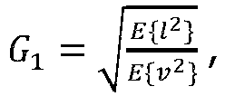
bandpass beamform signal 12A, v = A_1 ∗ l + B_1 ∗ r, and r is the contralateralbandpass beamform signal 14A. Thus, the compensation coefficient is the square root of the intensity ratio before and after beamforming and the bandpass sub-band is up-scaled to its original RMS level. - The
bandpass beamform controller 52 is configured to determine, e.g. withdeterminer 52A, first bandpass coefficient A_1 and contralateral bandpass coefficient B_1 by solving a minimization problem given by cost function C and constraint as described above using the stochastic steepest descent algorithm. - Thus, in the
bandpass beamformer 17A, the second bandpass beamform signal 18A also denoted X_1 is given by:
bandpass beamform signal 12A and r is the contralateralbandpass beamform signal 14A. -
Fig. 5 is a flowchart of anexemplary method 100 at least useful for understanding the invention, the method being a method of operating a hearing device in a binaural hearing system comprising the hearing device and a contralateral hearing device. Themethod 100 comprises obtaining 102 a contralateral beamform signal from the contralateral hearing device and obtaining 104 a first microphone input signal and a second microphone input signal. Further, themethod 100 comprises providing 106 a first beamform signal based on the first microphone input signal and the second microphone input signal and filtering 108 the first beamform signal and the contralateral beamform signal to provide a first bandpass beamform signal and a contralateral bandpass beamform signal. The method proceeds to providing 110 a second bandpass beamform signal based on the first bandpass beamform signal and the contralateral bandpass beamform signal, wherein providing 110 a second bandpass beamform signal comprises applying adaptive beamforming to the first bandpass beamform signal and the contralateral bandpass beamform signal. Themethod 100 comprises providing 112 a beamformed input signal based on the second bandpass beamform signal, performing 114 hearing compensation processing on the beamformed input signal to provide an electrical output signal, and converting 116 the electrical output signal to an audio output signal. - Although particular features have been shown and described, it will be understood that they are not intended to limit the claimed invention, and it will be made obvious to those skilled in the art that various changes and modifications may be made without departing from the scope of the claimed invention. The specification and drawings are, accordingly to be regarded in an illustrative rather than restrictive sense. The claimed invention is intended to cover all alternatives, modifications within the scope of the appended claims.
Claims (12)
- A hearing device for a binaural hearing system comprising the hearing device and a contralateral hearing device, the hearing device comprising:a transceiver module for communication with a contralateral hearing device of the binaural hearing system, the transceiver module configured to obtain a contralateral bandpass beamform signal from the contralateral hearing device;a set of microphones comprising a first microphone for provision of a first microphone input signal, and a second microphone for provision of a second microphone input signal;a first beamforming module, connected to the set of microphones, for provision of a first beamform signal based on the first microphone input signal and the second microphone input signal;a filter bank connected to the first beamforming module for filtering the first beamform signal into a plurality of first sub-band beamform signals including a first bandpass beamform signal;a second beamforming module connected to the filter bank and connected directly to the transceiver module for receiving the contralateral bandpass beamform signal, the second beamforming module comprising a bandpass beamformer for provision of a second bandpass beamform signal based on the first bandpass beamform signal and the contralateral bandpass beamform signal;an adder, connected to the bandpass beamformer, for provision of a beamformed input signal based on the second bandpass beamform signal;a processor for processing the beamformed input signal and providing an electrical output signal based on the beamformed input signal; anda receiver for converting the electrical output signal to an audio output signal,wherein the bandpass beamformer of the second beamforming module is an adaptive beamformer.
- Hearing device according to claim 1, wherein the bandpass beamformer comprises a bandpass beamform controller and a first multiplier, wherein the bandpass beamformer is configured to determine a first bandpass coefficient for the first bandpass beamform signal based on the first bandpass beamform signal and the contralateral bandpass beamform signal, and to apply the first bandpass coefficient in the first multiplier.
- Hearing device according to claim 2, wherein the bandpass beamformer is configured to determine the first bandpass coefficient for the first bandpass beamform signal by solving a minimization problem based on expected power values of the first bandpass beamform signal and the contralateral bandpass beamform signal.
- Hearing device according to any of claims 2-3, wherein the bandpass beamformer is configured to determine the first bandpass coefficient for the first bandpass beamform signal by solving a minimization problem based on an expected mean square value of a linear combination of the first bandpass beamform signal and the contralateral bandpass beamform signal.
- Hearing device according to any of claims 2-4, wherein the bandpass beamformer comprises a contralateral multiplier, and wherein the bandpass beamform controller is configured to determine a contralateral bandpass coefficient for the contralateral bandpass beamform signal based on the first bandpass beamform signal and the contralateral bandpass beamform signal, and to apply the contralateral bandpass coefficient in the contralateral multiplier.
- Hearing device according to claim 5, wherein the bandpass beamform controller is configured to determine the contralateral bandpass coefficient for the contralateral bandpass beamform signal by solving a minimization problem based on expected power values of the first bandpass beamform signal and the contralateral bandpass beamform signal.
- Hearing device according to any of claims 5-6, wherein the bandpass beamform controller is configured to determine the contralateral bandpass coefficient for the contralateral bandpass beamform signal by solving a minimization problem based on an expected mean square value of a linear combination of the first bandpass beamform signal and the contralateral bandpass beamform signal.
- Hearing device according to any of claims 1-7, wherein the bandpass beamformer comprises a bandpass equalizer configured to provide the second bandpass beamform signal based on an equalizer input, wherein the equalizer input is based on the first bandpass beamform signal and/or the contralateral bandpass beamform signal.
- Hearing device according to any of claims 1-8, wherein the hearing device comprises a beamform controller connected to the second beamforming module for controlling the second beamforming module, wherein the beamforming controller is configured to apply, in the second beamforming module, a second primary beamforming scheme in a primary operating mode of the hearing device, and to apply, in the second beamforming module, a second secondary beamforming scheme in a secondary operating mode of the hearing device.
- Hearing device according to claim 9, wherein the beamform controller is connected to the first beamforming module for controlling the first beamforming module, wherein the beamforming controller is configured to apply, in the first beamforming module, a first primary beamforming scheme in the primary operating mode of the hearing device, and to apply a first secondary beamforming scheme in the secondary operating mode of the hearing device.
- Hearing device according to any of claims 1-10, wherein the first beamforming module is connected to the transceiver module, and wherein the transceiver module is configured for transmitting at least a part of the first beamform signal to the contralateral hearing device.
- A method of operating a hearing device in a binaural hearing system comprising the hearing device and a contralateral hearing device, the hearing device comprising a transceiver module, a first microphone, a second microphone, a first beamforming module, a filter bank, and a second beamforming module, the second beamforming module directly connected to the transceiver module for receiving a contralateral bandpass beamform signal, the method comprising:obtaining, with the transceiver module, the contralateral bandpass beamform signal from the contralateral hearing device;obtaining a first microphone input signal with the first microphone and a second microphone input signal with the second microphone;providing, with the first beamforming module, a first beamform signal based on the first microphone input signal and the second microphone input signal;filtering, with the filter bank, the first beamform signal into a plurality of first sub-band beamform signals to provide a first bandpass beamform signal;providing, with the second beamforming module, a second bandpass beamform signal based on the first bandpass beamform signal and the contralateral bandpass beamform signal;providing a beamformed input signal based on the second bandpass beamform signal;performing hearing compensation processing on the beamformed input signal to provide an electrical output signal; andconverting the electrical output signal to an audio output signal;wherein the act of providing the second bandpass beamform signal comprises applying adaptive beamforming to the first bandpass beamform signal and the contralateral bandpass beamform signal.
Priority Applications (1)
| Application Number | Priority Date | Filing Date | Title |
|---|---|---|---|
| EP23181448.4A EP4277300A1 (en) | 2017-03-29 | 2018-03-21 | Hearing device with adaptive sub-band beamforming and related method |
Applications Claiming Priority (3)
| Application Number | Priority Date | Filing Date | Title |
|---|---|---|---|
| US201762478445P | 2017-03-29 | 2017-03-29 | |
| DKPA201770327 | 2017-05-09 | ||
| EP18163126.8A EP3383067B1 (en) | 2017-03-29 | 2018-03-21 | Hearing device with adaptive sub-band beamforming and related method |
Related Parent Applications (1)
| Application Number | Title | Priority Date | Filing Date |
|---|---|---|---|
| EP18163126.8A Division EP3383067B1 (en) | 2017-03-29 | 2018-03-21 | Hearing device with adaptive sub-band beamforming and related method |
Related Child Applications (2)
| Application Number | Title | Priority Date | Filing Date |
|---|---|---|---|
| EP23181448.4A Division-Into EP4277300A1 (en) | 2017-03-29 | 2018-03-21 | Hearing device with adaptive sub-band beamforming and related method |
| EP23181448.4A Division EP4277300A1 (en) | 2017-03-29 | 2018-03-21 | Hearing device with adaptive sub-band beamforming and related method |
Publications (3)
| Publication Number | Publication Date |
|---|---|
| EP3761671A1 EP3761671A1 (en) | 2021-01-06 |
| EP3761671B1 true EP3761671B1 (en) | 2023-08-02 |
| EP3761671C0 EP3761671C0 (en) | 2023-08-02 |
Family
ID=61731710
Family Applications (2)
| Application Number | Title | Priority Date | Filing Date |
|---|---|---|---|
| EP18163126.8A Active EP3383067B1 (en) | 2017-03-29 | 2018-03-21 | Hearing device with adaptive sub-band beamforming and related method |
| EP20170594.4A Active EP3761671B1 (en) | 2017-03-29 | 2018-03-21 | Hearing device with adaptive sub-band beamforming and related method |
Family Applications Before (1)
| Application Number | Title | Priority Date | Filing Date |
|---|---|---|---|
| EP18163126.8A Active EP3383067B1 (en) | 2017-03-29 | 2018-03-21 | Hearing device with adaptive sub-band beamforming and related method |
Country Status (2)
| Country | Link |
|---|---|
| US (2) | US10555094B2 (en) |
| EP (2) | EP3383067B1 (en) |
Families Citing this family (5)
| Publication number | Priority date | Publication date | Assignee | Title |
|---|---|---|---|---|
| EP3711306A1 (en) * | 2017-11-15 | 2020-09-23 | Starkey Laboratories, Inc. | Interactive system for hearing devices |
| EP3672282B1 (en) * | 2018-12-21 | 2022-04-06 | Sivantos Pte. Ltd. | Method for beamforming in a binaural hearing aid |
| DE102019201879B3 (en) | 2019-02-13 | 2020-06-04 | Sivantos Pte. Ltd. | Method for operating a hearing system and hearing system |
| GB2598960A (en) * | 2020-09-22 | 2022-03-23 | Nokia Technologies Oy | Parametric spatial audio rendering with near-field effect |
| US20230328465A1 (en) * | 2022-03-25 | 2023-10-12 | Gn Hearing A/S | Method at a binaural hearing device system and a binaural hearing device system |
Family Cites Families (31)
| Publication number | Priority date | Publication date | Assignee | Title |
|---|---|---|---|---|
| WO2001097558A2 (en) | 2000-06-13 | 2001-12-20 | Gn Resound Corporation | Fixed polar-pattern-based adaptive directionality systems |
| EP1699261B1 (en) | 2005-03-01 | 2011-05-25 | Oticon A/S | System and method for determining directionality of sound detected by a hearing aid |
| GB0609248D0 (en) | 2006-05-10 | 2006-06-21 | Leuven K U Res & Dev | Binaural noise reduction preserving interaural transfer functions |
| WO2009034524A1 (en) | 2007-09-13 | 2009-03-19 | Koninklijke Philips Electronics N.V. | Apparatus and method for audio beam forming |
| DE102008015263B4 (en) | 2008-03-20 | 2011-12-15 | Siemens Medical Instruments Pte. Ltd. | Hearing system with subband signal exchange and corresponding method |
| US8515109B2 (en) | 2009-11-19 | 2013-08-20 | Gn Resound A/S | Hearing aid with beamforming capability |
| WO2010094812A2 (en) * | 2010-06-07 | 2010-08-26 | Phonak Ag | Bone conduction hearing aid system |
| DK3396980T3 (en) * | 2011-07-04 | 2021-04-26 | Gn Hearing As | Binaural compressor for directions |
| EP2544462B1 (en) * | 2011-07-04 | 2018-11-14 | GN Hearing A/S | Wireless binaural compressor |
| US8638960B2 (en) * | 2011-12-29 | 2014-01-28 | Gn Resound A/S | Hearing aid with improved localization |
| US9185499B2 (en) * | 2012-07-06 | 2015-11-10 | Gn Resound A/S | Binaural hearing aid with frequency unmasking |
| DE102012204877B3 (en) * | 2012-03-27 | 2013-04-18 | Siemens Medical Instruments Pte. Ltd. | Hearing device for a binaural supply and method for providing a binaural supply |
| EP3462452A1 (en) | 2012-08-24 | 2019-04-03 | Oticon A/s | Noise estimation for use with noise reduction and echo cancellation in personal communication |
| US9456286B2 (en) * | 2012-09-28 | 2016-09-27 | Sonova Ag | Method for operating a binaural hearing system and binaural hearing system |
| US9628905B2 (en) * | 2013-07-24 | 2017-04-18 | Mh Acoustics, Llc | Adaptive beamforming for eigenbeamforming microphone arrays |
| US20150172807A1 (en) | 2013-12-13 | 2015-06-18 | Gn Netcom A/S | Apparatus And A Method For Audio Signal Processing |
| EP2928210A1 (en) | 2014-04-03 | 2015-10-07 | Oticon A/s | A binaural hearing assistance system comprising binaural noise reduction |
| EP3252766B1 (en) * | 2016-05-30 | 2021-07-07 | Oticon A/s | An audio processing device and a method for estimating a signal-to-noise-ratio of a sound signal |
| US9949041B2 (en) | 2014-08-12 | 2018-04-17 | Starkey Laboratories, Inc. | Hearing assistance device with beamformer optimized using a priori spatial information |
| US9749757B2 (en) * | 2014-09-02 | 2017-08-29 | Oticon A/S | Binaural hearing system and method |
| EP3205119B1 (en) * | 2014-09-15 | 2020-05-13 | Sonova AG | Hearing assistance system and method |
| EP3245797B1 (en) | 2015-01-14 | 2019-01-02 | Widex A/S | Method of operating a hearing aid system and a hearing aid system |
| EP3101919B1 (en) | 2015-06-02 | 2020-02-19 | Oticon A/s | A peer to peer hearing system |
| DK3148217T3 (en) | 2015-09-24 | 2019-04-15 | Sivantos Pte Ltd | Method of using a binaural hearing system |
| EP3157268B1 (en) * | 2015-10-12 | 2021-06-30 | Oticon A/s | A hearing device and a hearing system configured to localize a sound source |
| EP3285500B1 (en) * | 2016-08-05 | 2021-03-10 | Oticon A/s | A binaural hearing system configured to localize a sound source |
| CN109891913B (en) * | 2016-08-24 | 2022-02-18 | 领先仿生公司 | Systems and methods for facilitating inter-aural level difference perception by preserving inter-aural level differences |
| WO2018038820A1 (en) * | 2016-08-24 | 2018-03-01 | Advanced Bionics Ag | Systems and methods for facilitating interaural level difference perception by enhancing the interaural level difference |
| DK3306956T3 (en) * | 2016-10-05 | 2019-10-28 | Oticon As | A BINAURAL RADIATION FORM FILTER, A HEARING SYSTEM AND HEARING DEVICE |
| EP3373602A1 (en) * | 2017-03-09 | 2018-09-12 | Oticon A/s | A method of localizing a sound source, a hearing device, and a hearing system |
| EP3373603B1 (en) * | 2017-03-09 | 2020-07-08 | Oticon A/s | A hearing device comprising a wireless receiver of sound |
-
2018
- 2018-01-25 US US15/880,334 patent/US10555094B2/en active Active
- 2018-03-21 EP EP18163126.8A patent/EP3383067B1/en active Active
- 2018-03-21 EP EP20170594.4A patent/EP3761671B1/en active Active
-
2019
- 2019-12-10 US US16/709,852 patent/US10848880B2/en active Active
Also Published As
| Publication number | Publication date |
|---|---|
| EP3383067A1 (en) | 2018-10-03 |
| EP3761671C0 (en) | 2023-08-02 |
| EP3383067B1 (en) | 2020-04-29 |
| US10848880B2 (en) | 2020-11-24 |
| US20180288535A1 (en) | 2018-10-04 |
| US20200112803A1 (en) | 2020-04-09 |
| EP3761671A1 (en) | 2021-01-06 |
| US10555094B2 (en) | 2020-02-04 |
Similar Documents
| Publication | Publication Date | Title |
|---|---|---|
| EP3761671B1 (en) | Hearing device with adaptive sub-band beamforming and related method | |
| US11917370B2 (en) | Hearing device and a hearing system comprising a multitude of adaptive two channel beamformers | |
| CN105872923B (en) | Hearing system comprising a binaural speech intelligibility predictor | |
| AU2008207437B2 (en) | Method of estimating weighting function of audio signals in a hearing aid | |
| CN109951785B (en) | Hearing device and binaural hearing system comprising a binaural noise reduction system | |
| US8532307B2 (en) | Method and system for providing binaural hearing assistance | |
| CN108694956B (en) | Hearing device with adaptive sub-band beamforming and related methods | |
| EP3306956B1 (en) | A binaural beamformer filtering unit, a hearing system and a hearing device | |
| CN112492434A (en) | Hearing device comprising a noise reduction system | |
| EP3340655A1 (en) | Hearing device with adaptive binaural auditory steering and related method | |
| EP4277300A1 (en) | Hearing device with adaptive sub-band beamforming and related method | |
| EP3981172A1 (en) | Bilateral hearing aid system comprising temporal decorrelation beamformers | |
| US10681476B2 (en) | Hearing device and method with flexible control of beamforming | |
| US11617037B2 (en) | Hearing device with omnidirectional sensitivity | |
| CN112087699B (en) | Binaural hearing system comprising frequency transfer | |
| CN111757233A (en) | Hearing device or system for evaluating and selecting external audio sources | |
| CN112087699A (en) | Binaural hearing system comprising frequency translation |
Legal Events
| Date | Code | Title | Description |
|---|---|---|---|
| PUAI | Public reference made under article 153(3) epc to a published international application that has entered the european phase |
Free format text: ORIGINAL CODE: 0009012 |
|
| STAA | Information on the status of an ep patent application or granted ep patent |
Free format text: STATUS: THE APPLICATION HAS BEEN PUBLISHED |
|
| AC | Divisional application: reference to earlier application |
Ref document number: 3383067 Country of ref document: EP Kind code of ref document: P |
|
| AK | Designated contracting states |
Kind code of ref document: A1 Designated state(s): AL AT BE BG CH CY CZ DE DK EE ES FI FR GB GR HR HU IE IS IT LI LT LU LV MC MK MT NL NO PL PT RO RS SE SI SK SM TR |
|
| STAA | Information on the status of an ep patent application or granted ep patent |
Free format text: STATUS: REQUEST FOR EXAMINATION WAS MADE |
|
| 17P | Request for examination filed |
Effective date: 20210705 |
|
| RBV | Designated contracting states (corrected) |
Designated state(s): AL AT BE BG CH CY CZ DE DK EE ES FI FR GB GR HR HU IE IS IT LI LT LU LV MC MK MT NL NO PL PT RO RS SE SI SK SM TR |
|
| GRAP | Despatch of communication of intention to grant a patent |
Free format text: ORIGINAL CODE: EPIDOSNIGR1 |
|
| STAA | Information on the status of an ep patent application or granted ep patent |
Free format text: STATUS: GRANT OF PATENT IS INTENDED |
|
| INTG | Intention to grant announced |
Effective date: 20221012 |
|
| GRAJ | Information related to disapproval of communication of intention to grant by the applicant or resumption of examination proceedings by the epo deleted |
Free format text: ORIGINAL CODE: EPIDOSDIGR1 |
|
| STAA | Information on the status of an ep patent application or granted ep patent |
Free format text: STATUS: REQUEST FOR EXAMINATION WAS MADE |
|
| GRAP | Despatch of communication of intention to grant a patent |
Free format text: ORIGINAL CODE: EPIDOSNIGR1 |
|
| STAA | Information on the status of an ep patent application or granted ep patent |
Free format text: STATUS: GRANT OF PATENT IS INTENDED |
|
| INTC | Intention to grant announced (deleted) | ||
| INTG | Intention to grant announced |
Effective date: 20230227 |
|
| GRAS | Grant fee paid |
Free format text: ORIGINAL CODE: EPIDOSNIGR3 |
|
| GRAA | (expected) grant |
Free format text: ORIGINAL CODE: 0009210 |
|
| STAA | Information on the status of an ep patent application or granted ep patent |
Free format text: STATUS: THE PATENT HAS BEEN GRANTED |
|
| AC | Divisional application: reference to earlier application |
Ref document number: 3383067 Country of ref document: EP Kind code of ref document: P |
|
| AK | Designated contracting states |
Kind code of ref document: B1 Designated state(s): AL AT BE BG CH CY CZ DE DK EE ES FI FR GB GR HR HU IE IS IT LI LT LU LV MC MK MT NL NO PL PT RO RS SE SI SK SM TR |
|
| REG | Reference to a national code |
Ref country code: GB Ref legal event code: FG4D |
|
| REG | Reference to a national code |
Ref country code: CH Ref legal event code: EP |
|
| REG | Reference to a national code |
Ref country code: DE Ref legal event code: R096 Ref document number: 602018054852 Country of ref document: DE |
|
| REG | Reference to a national code |
Ref country code: IE Ref legal event code: FG4D |
|
| U01 | Request for unitary effect filed |
Effective date: 20230829 |
|
| U07 | Unitary effect registered |
Designated state(s): AT BE BG DE DK EE FI FR IT LT LU LV MT NL PT SE SI Effective date: 20230904 |
|
| PG25 | Lapsed in a contracting state [announced via postgrant information from national office to epo] |
Ref country code: GR Free format text: LAPSE BECAUSE OF FAILURE TO SUBMIT A TRANSLATION OF THE DESCRIPTION OR TO PAY THE FEE WITHIN THE PRESCRIBED TIME-LIMIT Effective date: 20231103 |
|
| PG25 | Lapsed in a contracting state [announced via postgrant information from national office to epo] |
Ref country code: IS Free format text: LAPSE BECAUSE OF FAILURE TO SUBMIT A TRANSLATION OF THE DESCRIPTION OR TO PAY THE FEE WITHIN THE PRESCRIBED TIME-LIMIT Effective date: 20231202 |
|
| PG25 | Lapsed in a contracting state [announced via postgrant information from national office to epo] |
Ref country code: RS Free format text: LAPSE BECAUSE OF FAILURE TO SUBMIT A TRANSLATION OF THE DESCRIPTION OR TO PAY THE FEE WITHIN THE PRESCRIBED TIME-LIMIT Effective date: 20230802 Ref country code: NO Free format text: LAPSE BECAUSE OF FAILURE TO SUBMIT A TRANSLATION OF THE DESCRIPTION OR TO PAY THE FEE WITHIN THE PRESCRIBED TIME-LIMIT Effective date: 20231102 Ref country code: IS Free format text: LAPSE BECAUSE OF FAILURE TO SUBMIT A TRANSLATION OF THE DESCRIPTION OR TO PAY THE FEE WITHIN THE PRESCRIBED TIME-LIMIT Effective date: 20231202 Ref country code: HR Free format text: LAPSE BECAUSE OF FAILURE TO SUBMIT A TRANSLATION OF THE DESCRIPTION OR TO PAY THE FEE WITHIN THE PRESCRIBED TIME-LIMIT Effective date: 20230802 Ref country code: GR Free format text: LAPSE BECAUSE OF FAILURE TO SUBMIT A TRANSLATION OF THE DESCRIPTION OR TO PAY THE FEE WITHIN THE PRESCRIBED TIME-LIMIT Effective date: 20231103 |
|
| PG25 | Lapsed in a contracting state [announced via postgrant information from national office to epo] |
Ref country code: PL Free format text: LAPSE BECAUSE OF FAILURE TO SUBMIT A TRANSLATION OF THE DESCRIPTION OR TO PAY THE FEE WITHIN THE PRESCRIBED TIME-LIMIT Effective date: 20230802 |