EP3761487A1 - Armature - Google Patents
Armature Download PDFInfo
- Publication number
- EP3761487A1 EP3761487A1 EP19810809.4A EP19810809A EP3761487A1 EP 3761487 A1 EP3761487 A1 EP 3761487A1 EP 19810809 A EP19810809 A EP 19810809A EP 3761487 A1 EP3761487 A1 EP 3761487A1
- Authority
- EP
- European Patent Office
- Prior art keywords
- segment conductor
- parts
- segment
- chamfered
- conductor
- Prior art date
- Legal status (The legal status is an assumption and is not a legal conclusion. Google has not performed a legal analysis and makes no representation as to the accuracy of the status listed.)
- Granted
Links
Images






Classifications
-
- H—ELECTRICITY
- H02—GENERATION; CONVERSION OR DISTRIBUTION OF ELECTRIC POWER
- H02K—DYNAMO-ELECTRIC MACHINES
- H02K3/00—Details of windings
- H02K3/04—Windings characterised by the conductor shape, form or construction, e.g. with bar conductors
- H02K3/12—Windings characterised by the conductor shape, form or construction, e.g. with bar conductors arranged in slots
-
- H—ELECTRICITY
- H02—GENERATION; CONVERSION OR DISTRIBUTION OF ELECTRIC POWER
- H02K—DYNAMO-ELECTRIC MACHINES
- H02K15/00—Processes or apparatus specially adapted for manufacturing, assembling, maintaining or repairing of dynamo-electric machines
- H02K15/06—Embedding prefabricated windings in the machines
- H02K15/062—Windings in slots; Salient pole windings
- H02K15/064—Windings consisting of separate segments
-
- H—ELECTRICITY
- H02—GENERATION; CONVERSION OR DISTRIBUTION OF ELECTRIC POWER
- H02K—DYNAMO-ELECTRIC MACHINES
- H02K15/00—Processes or apparatus specially adapted for manufacturing, assembling, maintaining or repairing of dynamo-electric machines
- H02K15/06—Embedding prefabricated windings in the machines
- H02K15/062—Windings in slots; Salient pole windings
- H02K15/065—Windings consisting of complete sections, e.g. coils or waves
- H02K15/067—Windings consisting of complete sections, e.g. coils or waves inserted in parallel to the axis of the slots or inter-polar channels
-
- H—ELECTRICITY
- H02—GENERATION; CONVERSION OR DISTRIBUTION OF ELECTRIC POWER
- H02K—DYNAMO-ELECTRIC MACHINES
- H02K3/00—Details of windings
- H02K3/04—Windings characterised by the conductor shape, form or construction, e.g. with bar conductors
- H02K3/28—Layout of windings or of connections between windings
Definitions
- the present invention relates to an armature.
- an armature including an armature core provided with a plurality of slots extending in a central axis line direction.
- Such an armature is disclosed in, for example, JP 2006-141076 A .
- JP 2006-141076 A discloses a rotating electrical machine stator (hereinafter, referred to as "stator") including a stator core provided with a plurality of slots extending in a central axis line direction (axial direction).
- stator rotating electrical machine stator
- an end part of a linear part (leg part) of a one-side conductor segment disposed on one side in the axial direction of the stator core and an end part of a linear part (leg part) of an other-side conductor segment disposed on the other side in the axial direction of the stator core are joined together in a slot.
- an insulating insulator is disposed in the slot.
- the linear part of the one-side conductor segment and the linear part of the other-side conductor segment are inserted inside the insulating insulator disposed in the slot and are joined together. Specifically, a facing surface which is a plane axially perpendicular to the linear part of the one-side conductor segment and a facing surface which is a plane axially perpendicular to the linear part of the other-side conductor segment are joined together.
- the end part (facing surface) of the linear part of the one-side conductor segment and the end part (facing surface) of the linear part of the other-side conductor segment both have chamfered parts formed thereat.
- the chamfered parts are provided so as to intersect a circumferential direction when the linear part of the one-side conductor segment (the linear part of the other-side conductor segment) is viewed in a radial direction. That is, the chamfered parts are formed so as to extend in the radial direction when the linear part is viewed in the radial direction.
- the chamfered parts are provided on both circumferential sides of the end part of the linear part.
- the end part of the linear part has an end-thinning shape as viewed in the radial direction.
- the linear part of the one-side conductor segment (the linear part of the other-side conductor segment) can be easily inserted inside the insulating insulator.
- the chamfered facing surface of the linear part of the one-side conductor segment and the chamfered facing surface of the linear part of the other-side conductor segment are joined together with a conductive joint material, with the chamfered facing surfaces facing each other.
- Patent Literature 1 JP 2006-141076 A
- JP 2006-141076 A since the facing surface of the linear part of the one-side conductor segment and the facing surface of the linear part of the other-side conductor segment are both chamfered, the areas of the facing surfaces are relatively small. Hence, there is a possible problem of a shortage of a joint area available for joining together the linear part of the one-side conductor segment and the linear part of the other-side conductor segment.
- the invention is made to solve a problem such as that described above, and provides an armature capable of preventing a shortage of a joint area.
- an armature includes: an armature core provided with a plurality of slots extending in a central axis line direction; and a coil part having a plurality of segment conductors whose facing surfaces are joined together, the plurality of segment conductors being disposed so as to face the central axis line direction, and the plurality of segment conductors include a first segment conductor disposed on one side in the central axis line direction of the armature core; and a second segment conductor disposed on an other side in the central axis line direction of the armature core, the facing surfaces provided at an end part of the first segment conductor and an end part of the second segment conductor are disposed so as to overlap each other as viewed in a radial direction, the facing surfaces being portions where the first segment conductor and the second segment conductor are joined together, and the end part of at least one of the first segment conductor and the second segment conductor is provided with chamfered parts at edge parts
- facing surfaces which are portions where a first segment conductor and a second segment conductor are joined together and which are provided at an end part of the first segment conductor and an end part of the second segment conductor are disposed so as to overlap each other as viewed in the radial direction, and the end part of at least one of the first segment conductor and the second segment conductor is provided with chamfered parts at edge parts on both circumferential sides thereof.
- the facing surface of the first segment conductor and the facing surface of the second segment conductor are provided so as to overlap each other as viewed in the radial direction, even when chamfered parts are provided at the end part of at least one of the first segment conductor and the second segment conductor, the amount of reduction in the area of the facing surface can be reduced. As a result, a shortage of a joint area can be prevented.
- the stator 100 has an annular shape having a central axis line C1 at the center thereof. Note that the stator 100 is an example of an "armature" in the claims.
- an "axial direction (central axis line direction)" indicates, as shown in FIG. 1 , a direction (Z-direction) along the central axis line C1 of the stator 100 (a rotation axis line of a rotor 101).
- a "circumferential direction” indicates a circumferential direction (an A1-direction and an A2-direction) of the stator 100.
- a "radial direction” indicates a radial direction (R-direction) of the stator 100.
- a “radial inner side” indicates a direction (R1-direction) going toward the central axis line C1 of the stator 100 in the radial direction.
- a “radial outer side” indicates a direction (R2-direction) going toward the outside of the stator 100 in the radial direction.
- the stator 100 together with the rotor 101 forms a part of a rotating electrical machine 102.
- the rotating electrical machine 102 is constructed as, for example, a motor, a generator, or a motor-generator.
- the stator 100 is disposed on the radial outer side of the rotor 101 having permanent magnets (not shown) provided thereon. Namely, in the present embodiment, the stator 100 forms a part of the inner-rotor rotating electrical machine 102.
- the stator 100 includes a stator core 10, insulating members 20, and a coil part 30.
- the coil part 30 includes a first coil assembly 30a and a second coil assembly 30b.
- the coil part 30 includes a plurality of segment conductors 40.
- the stator core 10 is an example of an "armature core" in the claims.
- the stator core 10 has a cylindrical shape having the central axis line C1 (see FIG. 1 ) as its central axis.
- the stator core 10 is constructed by, for example, stacking a plurality of electromagnetic steel sheets (e.g., silicon steel sheets) in the axial direction.
- the stator core 10 is provided with a back yoke 11 having an annular shape as viewed in the axial direction; and a plurality of slots 12 provided on the radial inner side of the back yoke 11 and extending in the axial direction.
- the stator core 10 is provided with a plurality of teeth 13 on both circumferential sides of the slots 12.
- Each slot 12 is a portion surrounded by a wall part 11a of the back yoke 11 that is provided more on the radial outer side than a first other end surface 73 which will be described later, and circumferential side surfaces 13a of two teeth 13.
- the slot 12 is provided with an opening part 12a that opens on the radial inner side.
- the slot 12 opens on both axial sides.
- Each tooth 13 is formed so as to protrude from the back yoke 11 toward the radial inner side, and has projecting parts 13b formed at an end part on the radial inner side thereof, the projecting parts 13b forming opening parts 12a of slots 12.
- Each opening part 12a has an opening width W1 in the circumferential direction.
- the opening width W1 corresponds to a distance between end parts of projecting parts 13b of teeth 13.
- a width W2 of a portion of a slot 12 where the coil part 30 and an insulating member 20 are disposed is larger than the opening width W1.
- the slot 12 is constructed as a semi-open slot.
- the width W2 corresponds to a distance between circumferential side surfaces 13a of teeth 13 disposed on both circumferential sides of the slot 12.
- the width W2 of the slot 12 is substantially constant in the radial direction.
- each insulating member 20 is disposed between teeth 13 and segment conductors 40.
- the insulating member 20 includes a joint-portion covering part 21.
- the joint-portion covering part 21 is configured to cover at least the radial inner side of a joint portion 90 (described later) of one of a plurality of parallelly and radially arranged segment conductors 40 that is arranged on a side closest to an opening part 12a of a slot 12.
- the insulating members 20 are made of, for example, sheet-like insulating members such as aramid paper and polymer films, and have a function of ensuring insulation between the segment conductors 40 (the coil part 30) and the stator core 10.
- Each insulating member 20 is disposed between segment conductors 40 and circumferential side surfaces 13a of teeth 13 and between one of the plurality of segment conductors 40 that is disposed on the radially outermost side and a wall part 11a.
- each insulating member 20 includes collar parts 22 (cuff parts) formed so as to protrude from a slot 12 toward the axial outer side on both axial sides and to be folded back.
- Each insulating member 20 is disposed so as to entirely cover the circumference of a plurality of parallelly and radially arranged segment conductors 40 as viewed in an arrow "Z2" direction.
- both circumferential sides and both radial sides of leg parts 42a and 42b (described later) of the plurality of parallelly and radially arranged segment conductors 40 are covered by the insulating member 20.
- the coil part 30 is formed by axially combining and joining together the first coil assembly 30a provided on one axial side (an arrow "Z1" direction side) and the second coil assembly 30b provided on the other axial side (an arrow "Z2" direction side).
- the first coil assembly 30a and the second coil assembly 30b each are formed in annular shape having the same central axis line C1 as the stator core 10 (see FIG. 1 ) at the center thereof.
- the coil part 30 is constructed as, for example, wave-winding coils.
- the coil part 30 is constructed as 8-turn coils. Namely, as shown in FIG. 5 , the coil part 30 is configured such that eight segment conductors 40 are parallelly and radially arranged in each slot 12.
- the coil part 30 is configured such that by supplying three-phase alternating-current power to the coil part 30 from a power supply part (not shown), while current moves back and forth in the axial direction and flows in the circumferential direction, a magnetic flux is generated.
- the coil part 30 is connected using three-phase "Y" connection.
- the coil part 30 includes a U-phase coil part 30U, a V-phase coil part 30V, and a W-phase coil part 30W.
- the coil part 30 is provided with a plurality of neutral points N.
- the coil part 30 is four parallel-connected (star-connected).
- the U-phase coil part 30U is provided with four neutral-point connection end parts NtU and four power-line connection end parts PtU.
- the V-phase coil part 30V is provided with four neutral-point connection end parts NtV and four power-line connection end parts PtV.
- the W-phase coil part 30W is provided with four neutral-point connection end parts NtW and four power-line connection end parts PtW. Note that in the following description when the neutral-point connection end parts and the power-line connection end parts for the U-phase, the V-phase, and the W-phase are not particularly distinguished from each other, they are simply described as “neutral-point connection end parts Nt” and "power-line connection end parts Pt”.
- the first coil assembly 30a includes a plurality of (e.g., three) segment conductors for power-line connection 50 (hereinafter, referred to as "power conductors 50") which are segment conductors 40; a plurality of (e.g., two) segment conductors for neutral point connection 60 (hereinafter, referred to as “neutral point conductors 60") which are segment conductors 40; and a plurality of general conductors 41 which are conductors (general segment conductors 40) different than the power conductors 50 and the neutral point conductors 60 among the plurality of segment conductors 40 and which form the coil part 30.
- power conductors 50 e.g., three segment conductors for power-line connection 50
- neutral point conductors 60 segment conductors 40
- general conductors 41 which are conductors (general segment conductors 40) different than the power conductors 50 and the neutral point conductors 60 among the plurality of segment conductors 40 and which form the coil part 30.
- the second coil assembly 30b includes a plurality of general conductors 41.
- the second coil assembly 30b includes only a plurality of general conductors 41, and all of the power conductors 50 and the neutral point conductors 60 provided in the stator 100 are provided in the first coil assembly 30a.
- each segment conductor 40 is constructed as a rectangular conducting wire whose transverse section has a substantially rectangular shape.
- a conductor surface 40b of the segment conductor 40 is provided with an insulating film 40a having a thickness t1.
- the thickness t1 of the insulating film 40a is set to such a thickness, for example, that allows to ensure phase-to-phase insulation performance (insulation between coil end parts 43).
- a conductor main body 40c of the segment conductor 40 is made of, for example, a metal material (conductive material) such as copper or aluminum. Note that although FIG. 8 shows a magnitude relationship between thicknesses, etc., in an exaggerated manner for the sake of description, the configuration is not limited to the example shown in the drawing.
- a segment conductor 40 includes leg parts 42a and 42b which are disposed in slots 12; and a coil end part 43.
- the leg parts 42a and 42b indicate portions disposed in slots 12 from an axial location of an end surface 10a or 10b of the stator core 10, and the coil end part 43 indicates a portion that is formed so as to continue to the leg parts 42a and 42b and that is disposed more on the axial outer side than the end surface 10a or 10b of the stator core 10.
- the coil end part 43 has a bent shape that bends in the axial direction.
- the coil end part 43 has a crank portion 43a formed in crank shape that radially bends in a stepwise manner for an amount corresponding to the width of a single segment conductor 40 as viewed in the axial direction. That is, the radial width of the crank portion 43a is double the width of a single segment conductor 40.
- a general conductor 41 includes a pair of leg parts 42a and 42b disposed in different slots 12; and a coil end part 43 that connects the pair of leg parts 42a and 42b.
- the general conductor 41 has a substantially U-shape or a substantially J-shape as viewed from the radial inner side.
- the leg parts 42a and 42b are formed linearly in the axial direction. Note that leg parts 42a and 42b of the power conductors 50 and leg parts 42a and 42b of the neutral point conductors 60 are configured in the same manner as the leg parts 42a and 42b of the general conductors 41, and thus, description thereof is omitted.
- the coil pitch of the general conductors 41 is six.
- a pair of leg parts 42a and 42b are disposed at different circumferential locations corresponding to six slots 12.
- five slots are provided between a slot 12 in which a leg part 42a of a general conductor 41 is disposed and a slot 12 in which a leg part 42b is disposed.
- the pair of leg parts 42a and 42b have different axial lengths. Specifically, an axial length L1 of the leg part 42a is larger than an axial length L2 of the leg part 42b.
- the axial length L1 (L2) of the leg part 42a (42b) indicates a length from an end 75 (85) to an axial location corresponding to the end surface 10a (10b) in the axial direction of the stator core 10.
- the axial lengths L1 and L2 are smaller than an axial length L3 of the stator core 10.
- the axial length L3 of the stator core 10 indicates an axial distance (space) between the end surfaces 10a and 10b.
- the axial length L1 is larger than one-half of the axial length L3, and the axial length L2 is smaller than one-half of the axial length L3.
- the plurality of general conductors 41 include one-side general conductors 41a that are disposed on one axial side (the arrow "Z1" direction side) of the stator core 10 and included in the first coil assembly 30a; and other-side general conductors 41b that are disposed on the other axial side (the arrow "Z2" direction side) of the stator core 10 and included in the second coil assembly 30b.
- a first leg part 71 which is a leg part 42a of a first segment conductor 70 which is one of a plurality of segment conductors 40 that is included in the first coil assembly 30a and a second leg part 81 which is a leg part 42b of a second segment conductor 80 which is a segment conductor 40 included in the second coil assembly 30b and axially facing the first segment conductor 70 are joined together at a joint portion 90.
- a first leg part 71 which is a leg part 42b of a first segment conductor 70 which is a segment conductor 40 included in the first coil assembly 30a and a second leg part 81 which is a leg part 42a of a second segment conductor 80 which is a segment conductor 40 included in the second coil assembly 30b are joined together at a joint portion 90.
- the first leg part 71 includes a first facing surface 72 facing the radial outer side (an arrow "R2" direction side) and facing the second leg part 81.
- the first leg part 71 includes a first one end surface 74 provided on one radial side which is the same side as the first facing surface 72; and a first other end surface 73 provided on the other radial side.
- the second leg part 81 includes a second facing surface 82 facing the radial inner side (an arrow "R1" direction side) and facing the first facing surface 72.
- the second leg part 81 includes a second one end surface 84 provided on one radial side which is an opposite side to a second joint surface 82a; and a second other end surface 83 provided on the other radial side.
- the first facing surface 72 and the second facing surface 82 are an example of "facing surfaces" in the claims.
- the first other end surface 73 of the first segment conductor 70 is disposed so as to be offset (to protrude) more radially (R1-direction side) than the second other end surface 83 of the second segment conductor 80.
- the second one end surface 84 of the second segment conductor 80 is disposed so as to be offset (to protrude) more radially (R2-direction side) than the first one end surface 74 of the first segment conductor 70.
- the joint portion 90 is a portion of the coil part 30 shown in FIG. 10 , and is a portion including the first facing surface 72 and the second facing surface 82 and including a portion from an end 75 of the first leg part 71 to a boundary point 76 between the first facing surface 72 and the first one end surface 74 and a portion from an end 85 of the second leg part 81 to a boundary point 86 between the second facing surface 82 and the second other end surface 83.
- An other step part 111 is formed at a portion between the end 75 of the first leg part 71 and the boundary point 86 of the second leg part 81, which is a boundary portion between the first other end surface 73 and the second other end surface 83.
- a one step part 112 is formed at a portion between the boundary point 76 of the first leg part 71 and the end 85 of the second leg part 81, which is a boundary portion between the first one end surface 74 and the second one end surface 84.
- a step is formed so as to be recessed toward the inner sides of the segment conductors 40 in a direction from the first other end surface 73 to the second other end surface 83.
- a step is formed so as to be recessed toward the inner sides of the segment conductors 40 in a direction from the second one end surface 84 to the first one end surface 74.
- a first displacement width d1 which is a displacement width between a radial location P1 of the first other end surface 73 and a radial location P2 of the second other end surface 83 is, for example, greater than the thickness t1 of the insulating film 40a of the segment conductor 40.
- a plurality of (e.g., eight) first leg parts 71 and a plurality of (e.g., eight) second leg parts 81 are disposed in a slot 12 so as to be radially adjacent to each other. Namely, the plurality of first leg parts 71 are parallelly and radially arranged and the plurality of second leg parts 81 are parallelly and radially arranged.
- first facing surfaces 72 of the plurality of first leg parts 71 is disposed at a different axial location than another first facing surface 272 radially adjacent thereto which will be described later.
- second facing surfaces 82 of the plurality of second leg parts 81 is disposed at a different axial location than another second facing surface 282 radially adjacent thereto which will be described later.
- an axial location P11 of a joint portion 90 including a first facing surface 272 and a second facing surface 282 is a different location than an axial location P12 of a joint portion 90 including another first facing surface 72 and another second facing surface 82 which are radially adjacent to the first facing surface 272 and the second facing surface 282.
- first facing surface 272 and the second facing surface 282 are an example of "facing surfaces" in the claims.
- the first leg parts 71 and the second leg parts 81 are staggered in the radial direction.
- the first facing surface 72 of the first leg part 71 includes a first joint surface 72a which is inclined in an arrow "E11" direction; a first reverse inclined surface 72b which is inclined in an arrow "E12” direction; and a first separated and facing surface 72c which is inclined in an arrow "E13" direction.
- the second facing surface 82 of the second leg part 81 includes a second joint surface 82a which is inclined in an arrow "E21" direction; a second reverse inclined surface 82b which is inclined in an arrow "E22” direction; and a second separated and facing surface 82c which is inclined in an arrow "E23" direction.
- the first facing surface 72 of the first leg part 71 and the second facing surface 82 of the second leg part 81 are formed so as to be inclined with respect to the axial direction.
- the first facing surface 72 is constructed as an end surface that is inclined with respect to the axial direction in an arrow "E1" direction from the end 75 of the first leg part 71.
- the first facing surface 72 is not provided with an insulating film 40a.
- the second facing surface 82 is constructed as an end surface that is inclined in an arrow "E2" direction from the end 85 of the second leg part 81.
- the second facing surface 82 is not provided with an insulating film 40a.
- the arrow "E1" direction indicates a direction going from the end 75 toward the boundary point 76 between the first facing surface 72 and the first one end surface 74.
- the arrow “E2" direction indicates a direction going from the end 85 toward the boundary point 86 between the second facing surface 82 and the second other end surface 83.
- the first facing surface 72 and the second facing surface 82 each are formed such that its radial cross-section has an S-shape.
- the first facing surface 72 having an S-shape (uneven shape) and the second facing surface 82 having an S-shape (uneven shape) are disposed in a slot 12, with the first facing surface 72 and the second facing surface 82 being radially engaged with each other.
- the first facing surface 72 includes the first joint surface 72a which is joined to the second facing surface 82; and the first reverse inclined surface 72b which is formed continuously with the first joint surface 72a and which is inclined in an opposite direction (the arrow "E12" direction) to a direction in which the first joint surface 72a is inclined (the arrow "E11" direction) with respect to the axial direction (an axis parallel to the central axis line C1).
- the first joint surface 72a and the first reverse inclined surface 72b each are formed as a substantially flat surface, and the first joint surface 72a and the first reverse inclined surface 72b form a bent shape.
- the second facing surface 82 includes the second joint surface 82a which is joined to the first joint surface 72a; and the second reverse inclined surface 82b which is formed continuously with the second joint surface 82a and which is inclined in an opposite direction (the arrow "E22" direction) to a direction in which the second joint surface 82a is inclined (the arrow "E21" direction) with respect to the axial direction.
- the joint material 130 is disposed between the first joint surface 72a and the second joint surface 82a, by which the first joint surface 72a and the second joint surface 82a are joined together and electrically connected to each other.
- the joint material 130 includes a conductive material such as silver or copper.
- the joint material 130 is a paste-like joint material (silver nanopaste) in which a solvent contains, as conductive particles, metal particles obtained by grinding silver into fine particles of a nanometer level.
- the joint material 130 contains a component (resin component) that is volatilized when heated, and has a function of allowing the first joint surface 72a and the second joint surface 82a to come close to each other by a reduction in the volume of the joint material 130 by heating the component that is volatilized.
- a component resin component
- the first facing surface 72 includes the first separated and facing surface 72c which is formed continuously on an opposite side to the first joint surface 72a side of the first reverse inclined surface 72b and which is disposed so as to be separated from the second facing surface 82.
- the second facing surface 82 includes the second separated and facing surface 82c which is formed continuously on an opposite side to the second joint surface 82a side of the second reverse inclined surface 82b and which is disposed so as to be separated from the first facing surface 72.
- first separated and facing surface 72c is inclined in the arrow "E13" direction which is an axially (an axis parallel to the central axis line C1) opposite direction to the first reverse inclined surface 72b.
- second separated and facing surface 82c is inclined in the arrow "E23" direction which is an axially opposite direction (the axis parallel to the central axis line C1) to the second reverse inclined surface 82b.
- the second separated and facing surface 82c is disposed so as to face the first separated and facing surface 72c, and clearance CL is made between the first separated and facing surface 72c and the second separated and facing surface 82c.
- end 75 of the first leg part 71 and the end 85 of the second leg part 81 are formed on flat planes orthogonal to each other in the axial direction.
- FIG. 10 shows that the end side of the first leg part 71 has a shape in which the end is thinner than the end side (end-thickening shape) of the second leg part 81
- one side (the leg part 42a having the axial length L1) of the first leg part 71 has an end-thinning shape shown in FIG. 10
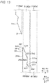
- the other side (the leg part 42b having the axial length L2) of the first leg part 71 has an end-thickening shape shown in FIG. 13 .
- the leg part 42a of the second leg part 81 (see FIG. 13 ) has an end-thinning shape
- the leg part 42b of the second leg part 81 (see FIG. 10 ) has an end-thickening shape. That is, the first segment conductor 70 and the second segment conductor 80 have substantially the same shape.
- a first joint surface 272a included in a first facing surface 272 of the first segment conductor 70 and a second joint surface 282a included in a second facing surface 282 of the second segment conductor 80 are joined together.
- a first facing surface 72 of a first segment conductor 70 and a second facing surface 82 of a second segment conductor 80 which are provided at an end part 71a of the first segment conductor 70 and an end part 81a of the second segment conductor 80 are disposed so as to overlap each other as viewed in the radial direction.
- substantially the entire first facing surface 72 and substantially the entire second facing surface 82 overlap each other as viewed in the radial direction.
- the first facing surface 72 of the first segment conductor 70 and the second facing surface 82 of the second segment conductor 80 are disposed so as to radially face each other.
- the end part 71a of the first segment conductor 70 (leg part 42a) is provided with chamfered parts 77 at edge parts 71d on both circumferential sides thereof (as viewed in the radial direction).
- the end part 81a of the second segment conductor 80 (leg part 42b) is provided with chamfered parts 87 at edge parts 81d on both circumferential sides thereof.
- an end part 271a of the first segment conductor 70 (leg part 42b) is provided with chamfered parts 277 at edge parts 271d on both circumferential sides thereof.
- an end part 281a of the second segment conductor 80 (leg part 42a) is provided with chamfered parts 287 at edge parts 281d on both circumferential sides thereof.
- a specific configuration of the chamfered parts 77, the chamfered parts 277, the chamfered parts 87, and the chamfered parts 287 will be described below. Note that the chamfered parts 77, the chamfered parts 277, the chamfered parts 87, and the chamfered parts 287 have the same configuration and thus the chamfered parts 77 will be mainly described.
- chamfered parts 77 are provided on both circumferential sides of an end part 71a of a first segment conductor 70 as viewed in the radial direction. Specifically, by chamfering two corner parts 71b of the end part 71a, chamfered parts 77 are formed.
- a total circumferential length L11 of the chamfered parts 77 provided on both circumferential sides of the end part 71a (double a circumferential length L13 of a single chamfered part 77) is smaller than a circumferential length L12 of a portion 71c of the end part 71a other than the chamfered parts 77.
- the total length L11 is less than one-half of the length L12.
- the chamfered parts 77 are provided so as to intersect the central axis line direction at an angle ⁇ 1 of 45 degrees or more as viewed in the radial direction. In other words, the chamfered parts 77 are provided so as to intersect the circumferential direction at an angle of less than 45 degrees as viewed in the radial direction. Note that in the present embodiment the chamfered parts 77 intersect the central axis line direction at an angle ⁇ 1 of substantially 45 degrees.
- an angle ⁇ 2 formed by each chamfered part 77 and the portion 71c of the end part 71a other than the chamfered parts 77 is an obtuse angle.
- the chamfered parts 77 are provided at a first joint surface 72a. That is, by chamfering parts (corner parts) of the first joint surface 72a, chamfered parts 77 are formed. Note that chamfered parts 287 (see FIG. 13 ) are provided at a second joint surface 282a. In addition, chamfered parts 277 are provided at portions of a first leg part 71 more on the end side than a first joint surface 272a. In addition, the chamfered parts 287 are provided at portions of a second leg part 81 more on the end side than the second joint surface 282a.
- the first joint surface 72a and the second joint surface 82a both are provided so as to intersect the central axis line direction as viewed in the circumferential direction.
- the chamfered parts 77 are provided at the first joint surface 72a which is provided so as to intersect the central axis line direction. That is, the chamfered parts 77 are provided at the end part 71a of the first segment conductor 70 having an end-thinning shape.
- the chamfered parts 287 are provided at the second joint surface 282a which is provided so as to intersect the central axis line direction. That is, the chamfered parts 287 are provided at the end part 281a of the second segment conductor 80 having an end-thinning shape.
- an insulating member 20 is disposed so as to cover inner surfaces on the circumferential side of a slot 12 (circumferential side surfaces 13a of teeth 13) and an inner surface on the radial side of the slot 12 (a wall part 11a of the back yoke 11).
- the chamfered parts 77 are provided at edge parts 71d on the circumferential side of the first facing surface 72 (side surfaces on the circumferential side of the end part 71a) that face the insulating member 20.
- the edge parts 71d on the circumferential side of the end part 71a are disposed so as to be in contact with the insulating member 20 or to be slightly spaced apart from the insulating member 20.
- the chamfered parts 77 have a linear shape that linearly intersects a plane perpendicular to the central axis line direction. That is, the chamfered parts 77 have a flat plane shape.
- corner parts 71e (four corner parts 71e) of the leg part 42a are chamfered, and the chamfered parts 77 are provided separately from this chamfering.
- chamfered parts 87 are provided at edge parts 81d on both circumferential sides of an end part 81a of a second segment conductor 80 as viewed in the radial direction (see FIG. 12 ).
- the total circumferential length of the chamfered parts 87, the angle of inclination of the chamfered parts 87 with respect to the central axis line direction, and the shape (linear shape) of the chamfered parts 87 are the same as those of the above-described chamfered parts 77.
- chamfered parts 277 are provided at edge parts 271d on both circumferential sides of an end part 271a (see FIG. 13 ) of the first segment conductor 70 as viewed in the radial direction.
- the total circumferential length of the chamfered parts 277, the angle of inclination of the chamfered parts 277 with respect to the central axis line direction, and the shape (linear shape) of the chamfered parts 277 are the same as those of the above-described chamfered parts 77.
- chamfered parts 287 are provided at edge parts 281d on both circumferential sides of an end part 281a (see FIG. 13 ) of the second segment conductor 80 as viewed in the radial direction.
- the total circumferential length of the chamfered parts 287, the angle of inclination of the chamfered parts 287 with respect to the central axis line direction, and the shape (linear shape) of the chamfered parts 287 are the same as those of the above-described chamfered parts 77.
- the first facing surface 72 (272) of the first segment conductor 70 and the second facing surface 82 (282) of the second segment conductor 80 are provided so as to radially face each other and extend in the central axis line direction.
- the chamfered parts 77 (277, 87, 287) are provided at an end and edge parts on both circumferential sides of at least one (both in the present embodiment) of the first facing surface 72 (272) of the first segment conductor 70 and the second facing surface 82 (282) of the second segment conductor 80.
- the first segment conductor 70 includes the first other end surface 73 provided on a radially opposite side to the first facing surface 72 (272) and provided so as to extend in the central axis line direction.
- the second segment conductor 80 includes the second one end surface 84 provided on a radially opposite side to the second facing surface 82 (282) and provided so as to extend in the central axis line direction.
- the chamfered parts 77 (277, 87, 287) are provided at an end and edge parts on both circumferential sides of at least one (both in the present embodiment) of the first other end surface 73 of the first segment conductor 70 and the second one end surface 84 of the second segment conductor 80.
- the first other end surface 73 and the second one end surface 84 are an example of "back surfaces" in the claims.
- a line segment L21 that forms an outer edge of the chamfered part 77 (277) provided at the first facing surface 72 (272) and a line segment L22 that forms an outer edge of the chamfered part 77 (277) provided at the first other end surface 73 are provided on the same plane.
- a line segment L23 that forms an outer edge of the chamfered part 87 (287) provided at the second facing surface 82 (282) and a line segment L24 that forms an outer edge of the chamfered part 87 (287) provided at the second one end surface 84 are provided on the same plane.
- the coil part 30 is provided with insulating parts 120.
- One of a plurality of parallelly arranged segment conductors 40 has an insulating part 120 provided at a portion of a conductor surface 40b thereof (see FIG. 8(b) ) at an axial location corresponding to a joint portion 90 of other segment conductors 40 disposed so as to be radially adjacent to the one segment conductor 40 (hereinafter, this joint portion 90 is referred to as "adjacent joint portion 90"), the insulating part 120 having a thickness t2 larger than a thickness t1 of an insulating film 40a of the adjacent joint portion 90.
- the manufacturing device 200 for the stator 100 includes pressing jigs 201.
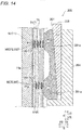
- the pressing jigs 201 independently and radially press the first leg parts 71 of the first segment conductors 70 and the second leg parts 81 of the second segment conductors 80 which are disposed in the plurality of slots 12, on a per slot 12 basis.
- the pressing jigs 201 are disposed for the respective plurality of slots 12 and configured to be radially movable.
- a plurality of (the same number as the number of the slots 12) pressing jigs 201 are provided for the respective plurality of slots 12 and configured to be independently and radially movable on a per pressing jig 201 basis.
- the manufacturing device 200 for the stator 100 includes movement mechanism parts 202 that allow the pressing jigs 201 to independently move on a per slot 12 basis.
- the movement mechanism parts 202 are provided for the respective plurality of pressing jigs 201 and configured to be able to adjust the amount of radial movement on a per pressing jig 201 basis.
- the movement mechanism parts 202 are composed of, for example, actuators.
- each pressing jig 201 includes contact portions 201a that come into contact with a first segment conductor 70 and a second segment conductor 80.
- Each contact portion 201a has a shape whose corner parts are chamfered as viewed in the circumferential direction.
- two contact portions 201a are provided so as to protrude toward the radial outer side.
- the two contact portions 201a are provided so as to be axially separated from each other.
- the two contact portions 201a are configured to press locations corresponding to joint portions 90 of leg parts 42a and 42b (see FIG. 14 ).
- the manufacturing device 200 for the stator 100 is provided with a push-out member 203 and a holding member 204.
- the holding member 204 is configured to hold the pressing jig 201 and the push-out member 203.
- the push-out member 203 is formed, for example, in wedge shape (tapered shape) that becomes gradually thinner toward one axial side, and is configured such that axial movement of the push-out member 203 presses (pushes out) the pressing jig 201 toward the radial outer side, and a pressing force is transmitted to segment conductors 40 while allowing the pressing jig 201 to move toward the radial outer side.
- FIG. 18 shows a flowchart for describing the method for manufacturing the stator 100.
- a plurality of segment conductors 40 are prepared. Specifically, there are prepared power conductors 50 that form power-line connection end parts Pt for the respective phases of a Y-connected coil part 30; neutral point conductors 60 that form neutral point connection end parts Nt for the respective phases of the coil part 30; and general conductors 41 that form other portions of the coil part 30.
- an insulating film 40a made of an insulating material such as polyimide is formed (coated) on a rectangular conductor surface 40b made of a conductive material such as copper.
- conductors (rectangular conducting wires) having the insulating films 40a formed thereon are shaped by a forming jig (not shown), by which general conductors 41 (see FIG. 9 ), outside diameter side power conductors 52 and inside diameter side power conductors 53 for forming power conductors 50, outside diameter side neutral point conductors 61, and inside diameter side neutral point conductors 62 are formed.
- chamfered parts 77 and chamfered parts 277 are formed in advance at first leg parts 71 (a leg part 42a and a leg part 42b) of a first segment conductor 70.
- chamfered parts 87 and chamfered parts 287 are formed in advance at second leg parts 81 (a leg part 42a and a leg part 42b) of a second segment conductor 80.
- step S2 an insulating part 120 having a thickness t2 larger than a thickness t1 of the insulating film 40a formed at a joint portion 90 is provided on the conductor surface 40b of each segment conductor 40.
- an insulating part 120 is formed. Specifically, an insulating member 121 is mounted on each of the leg parts 42a of the general conductors 41, the leg parts 42a of the outside diameter side power conductors 52, and the leg parts 42a of the outside diameter side neutral point conductors 61.
- a sheet-like insulating member 121 having a thickness t3 smaller than the thickness t1 is wound around a leg part 42a once or more and fixed.
- a first coil assembly 30a and a second coil assembly 30b each having an annular shape and including a plurality of segment conductors 40 are formed.
- a first coil assembly 30a and a second coil assembly 30b each having an annular shape and including a plurality of segment conductors 40 are formed such that the insulating part 120 of one segment conductor 40 is located in a position radially adjacent to a joint portion 90 of other segment conductors 40 disposed so as to be radially adjacent to the one segment conductor 40.
- FIG. 3 only shows some (two) of the plurality of insulating parts 120 by hatching for the sake of description, in the present embodiment, all leg parts 42a are provided with the insulating parts 120.
- the segment conductors 40 are formed such that a plurality of (e.g., eight) segment conductors 40 are parallelly and radially arranged, and such a number of segment conductors 40 that is equal to the number of the slots 12 are parallelly and circumferentially arranged.
- the first coil assembly 30a and the second coil assembly 30b are formed such that the insulating part 120 of one of the plurality of parallelly arranged segment conductors 40 is located in an axial position corresponding to a joint portion 90 of other segment conductors 40 disposed so as to be radially adjacent to the one segment conductor 40.
- an insulating member 20 is disposed in each of the plurality of slots 12.
- the insulating member 20 is disposed so as to be exposed or open on both axial sides and closed on the radial inner side.
- the disposed insulating member 20 is held in the slot 12 by collar parts 22 on both axial sides.
- the plurality of segment conductors 40 are disposed in the plurality of slots 12. Specifically, the first coil assembly 30a and the second coil assembly 30b are allowed to axially move relative to each other toward the plurality of slots 12, by which each of the leg parts 42a and 42b of the first coil assembly 30a and the second coil assembly 30b is disposed in one of the plurality of slots 12.
- the first coil assembly 30a is allowed to move in parallel (linearly move) to the stator core 10 in the arrow "Z2" direction and the second coil assembly 30b is allowed to move in parallel (linearly move) to the stator core 10 in the arrow "Z1" direction, by which each of the leg parts 42a and 42b is disposed in one of the plurality of slots 12 (the slots 12 having the insulating members 20 disposed therein).
- a leg part 42a of a first segment conductor 70 is provided with chamfered parts 77, when the leg part 42a is inserted into a slot 12 (in space enclosed by an insulating member 20), an end part (an end part 71a) of the leg part 42a can be prevented from getting stuck in corner parts of the slot 12 (corner parts of teeth 13).
- a leg part 42b of the first segment conductor 70 is provided with chamfered parts 277, when the leg part 42b is inserted into a slot 12, an end part 71a of the leg part 42b can be prevented from getting stuck in corner parts of the slot 12.
- leg parts 42a and 42b of a second segment conductor 80 are provided with chamfered parts 87 and 287, respectively, end parts 81a and 281a can be prevented from getting stuck in corner parts of slots 12.
- the insulating members 20 can be prevented from getting damaged by the corner parts of the leg parts 42a and the leg parts 42b inserted in the slots 12 (in pieces of space enclosed by the insulating members 20).
- the plurality of segment conductors 40 are disposed in the slots 12 such that the insulating part 120 of one of a plurality of parallelly and radially arranged segment conductors 40 is located in an axial position corresponding to a joint portion 90 disposed so as to be radially adjacent to the insulating part 120.
- step S6 as shown in FIG. 14 , as shown in FIG. 14 , the first leg parts 71 of the first segment conductors 70 and the second leg parts 81 of the second segment conductors 80 that axially face the first segment conductors 70 are radially pressed (pressurized) on a per slot 12 basis, by which the first leg parts 71 and the second leg parts 81 are joined together in the slot 12.
- a joint portion 90 by heating at least a joint material 130 by a heating device (not shown) while leg parts 42a and 42b are pressed by a pressing jig 201, at least a part of a first facing surface 72 and at least a part of a second facing surface 82 are joined together, forming a joint portion 90.
- a first joint surface 72a see FIG. 10
- a second joint surface 82a are joined together.
- a first joint surface 272a see FIG. 13
- a second joint surface 282a are joined together.
- first leg parts 71 of a power conductor 50 and a neutral point conductor 60 and second leg parts 81 which are either one of leg parts 42a and 42b of general conductors 41 are joined together, and in another slot 12, second leg parts 81 which are the other one of the leg parts 42a and 42b of the general conductors 41 and first leg parts 71 of general conductors 41 are joined together.
- second leg parts 81 which are the other one of the leg parts 42a and 42b of the general conductors 41 and first leg parts 71 of general conductors 41 are joined together.
- a portion where a first leg part 71 and a second leg part 81 are joined together serves as an electrically joined joint portion 90.
- an insulating part 120 is disposed at a location (axial location) radially adjacent to the joint portion 90.
- an axial location P11 of a joint portion 90 is a different location than an axial location P12 of a joint portion 90 of segment conductors 40 radially adjacent thereto.
- first leg parts 71 and the second leg parts 81 together with the insulating members 20 whose radial inner sides are closed are pressed by the pressing jigs 201 from the radial inner side.
- a stator 100 is completed. Note that as shown in FIG. 1 , by combining the stator 100 with a rotor 101, a rotating electrical machine 102 is manufactured.
- facing surfaces (72, 82, 272, 282) which are portions where a first segment conductor (70) and a second segment conductor (80) are joined together and which are provided at an end part (71a, 271a) of the first segment conductor (70) and an end part (81a, 281a) of the second segment conductor (80) are disposed so as to overlap each other as viewed in the radial direction, and the end part (71a, 271a) of the first segment conductor (70) and the end part (81a, 281a) of the second segment conductor (80) each are provided with chamfered parts (77, 87, 277, 287) at edge parts on both circumferential sides thereof (71d, 81d, 271d, 281d).
- the facing surface (72, 272) of the first segment conductor (70) and the facing surface (82, 282) of the second segment conductor (80) are provided so as to overlap each other as viewed in the radial direction, even when chamfered parts (77, 87, 277, 287) are provided at the end part of at least one of the first segment conductor (70) and the second segment conductor (80), the amount of reduction in the area of the facing surface (72, 82, 272, 282) can be reduced. As a result, a shortage of a joint area can be prevented.
- the end part (71a, 271a) of the first segment conductor (70) and the end part (81a, 281a) of the second segment conductor (80) each are provided with the chamfered parts (77, 87, 277, 287) at edge parts on both circumferential sides thereof (71d, 81d, 271d, 281d), when the first segment conductor (70) and the second segment conductor (80) are inserted into a slot (12), at least one of the first segment conductor (70) and the second segment conductor (80) can be smoothly inserted into the slot (12).
- the leg parts (42a, 42b) can be appropriately bonded together while the insertion properties of the leg parts (42a, 42b) into the slot (12) improve.
- the end part (71a, 271a) of the first segment conductor (70) and the end part (81a, 281a) of the second segment conductor (80) are provided with the chamfered parts (77, 87, 277, 287), an insulating member (20) disposed in the slot (12) can be prevented from getting damaged by the first segment conductor (70) and the second segment conductor (80).
- a total circumferential length (L11) of the chamfered parts (77, 87, 277, 287) provided on both circumferential sides of the end part (71a, 81a, 271a, 281a) is smaller than a circumferential length (L12) of a portion (71C) of the end part (71a, 81a, 271a, 281a) other than the chamfered parts (77, 87, 277, 287).
- the size of the chamfered parts (77, 87, 277, 287) is relatively small, and thus, a reduction in the size of the end part (71a, 81a, 271a, 281a) where the facing surface (72, 82, 272, 282) is provided can be prevented.
- joint strength between the leg parts (42a, 42b) can be ensured.
- the chamfered parts (77, 87, 277, 287) are provided so as to intersect the central axis line direction at an angle of 45 degrees or more as viewed in the radial direction.
- the chamfered parts (77, 287) are provided at a first joint surface (72a) and a second joint surface (282a).
- the chamfered parts (77, 287) are provided at the first joint surface (72a) (the second joint surface (282a)) that comes into contact with corners of a slot (12) (corners of teeth (13)) at a relatively early stage upon inserting the first segment conductor (70) (the second segment conductor (80)) into the slot (12), the first segment conductor (70) (the second segment conductor (80)) can be more smoothly inserted into the slot (12).
- the chamfered parts (77, 287) are provided at the first joint surface (72a) and the second joint surface (282a) which are provided so as to intersect the central axis line direction.
- the chamfered parts (77, 287) at the first joint surface (72a) and the second joint surface (282a) which are provided so as to intersect the central axis line direction, the influence of a reduction in joint area caused by the formation of the chamfered parts (77, 287) can be reduced.
- the chamfered parts (77, 87, 277, 287) are provided at both of the end parts (71a, 271a) of the first segment conductor (70) and the end parts (81a, 281a) of the second segment conductor (80).
- the chamfered parts (77, 87, 277, 287) are provided at the edge parts (71d, 81d, 271d, 281d) on the circumferential side of the facing surface (72, 82, 272, 282) that face an insulating member (20).
- the chamfered parts (77, 87, 277, 287) are provided at the edge parts (71d, 81d, 271d, 281d) of the facing surface (72, 82, 272, 282) that face the insulating member (20), damage to the insulating member (20) can be effectively prevented.
- the chamfered parts (77, 87, 277, 287) have a linear shape that linearly intersects the circumferential direction as viewed in the radial direction.
- the chamfered parts (77, 87, 277, 287) have a relatively simple shape, the chamfered parts (77, 87, 277, 287) can be easily formed.
- a first leg part (71) of the first segment conductor (70) and a second leg part (81) of the second segment conductor (80) are joined together in a slot (12).
- the end part (71a, 271a) of the first segment conductor (70) and the end part (81a, 281a) of the second segment conductor (80) each are provided with the chamfered parts (77, 87, 277, 287) at edge parts on both circumferential sides thereof (71d, 81d, 271d, 281d)
- the first leg part (71) and the second leg part (81) can be smoothly inserted into the slot (12) and joined together.
- the facing surface (72, 272) of the first segment conductor (70) and the facing surface (82, 282) of the second segment conductor (80) are provided so as to radially face each other and extend in the central axis line direction.
- the chamfered parts (77, 87, 277, 287) are provided at an end and edge parts on both circumferential sides of at least one of the facing surface (72, 272) of the first segment conductor (70) and the facing surface (82, 282) of the second segment conductor (80).
- the first segment conductor (70) and the second segment conductor (80) each include a back surface (73, 84) provided on a radially opposite side to the facing surface (72, 82, 272, 282) and provided so as to extend in the central axis line direction.
- the chamfered parts (77, 87, 277, 287) are provided at an end and edge parts on both circumferential sides of at least one of the back surface (73) of the first segment conductor (70) and the back surface (84) of the second segment conductor (80).
- the chamfered parts (77, 87, 277, 287) are provided so as to go across from the facing surface (72, 82, 272, 282) to the back surface (73, 84), the first segment conductor (70) and the second segment conductor (80) can be smoothly inserted into the slot (12).
- a line segment (L21, L23) that forms an outer edge of the chamfered part (77, 87, 277, 287) provided at the facing surface (72, 82, 272, 282) and a line segment (L22, L24) that forms an outer edge of the chamfered part (77, 87, 277, 287) provided at the back surface (73, 84) are provided on the same plane.
- the present invention is not limited thereto.
- the two leg parts of the segment conductor may have the same length.
- chamfered parts are provided so as to intersect the central axis line direction at an angle of substantially 45 degrees as viewed in the radial direction
- the present invention is not limited thereto.
- the chamfered parts may be provided so as to intersect the central axis line direction at an angle of greater than 45 degrees as viewed in the radial direction.
- the present invention is not limited thereto.
- the chamfered parts may be provided at only one of the pair of leg parts.
- the chamfered parts are provided at both of first leg parts of a first segment conductor and second leg parts of a second segment conductor
- the present invention is not limited thereto.
- the chamfered parts may be provided at only the first leg parts of the first segment conductor without being provided at the second segment conductor, or may be provided at only the second leg parts of the second segment conductor without being provided at the first segment conductor.
- chamfered parts 377 may be configured to have a round shape (R-shape) as viewed in the radial direction.
- R-shape round shape
- a chamfered part 677 may be provided at an end part of a first segment conductor 70 (second segment conductor 80) as viewed in the circumferential direction in addition to the radial direction. That is, the end part is provided with both of chamfered parts 577 that intersect the central axis line direction as viewed in the radial direction (see FIG.
- the segment conductor being inserted can be prevented from getting stuck in a segment conductor (a first segment conductor 70 or a second segment conductor 80) disposed so as to be radially adjacent thereto.
- the insertion properties of the first segment conductor 70 and the second segment conductor 80 into the slot 12 can be further improved.
- a leg part of a first segment conductor and a second leg part of a second segment conductor may be joined together on an axial outside of an end surface (10a or 10b) of the stator core.
- facing surfaces where the leg parts are joined together are disposed on the axial outside of the end surface (10a or 10b) of the stator core.
- first joint surface 72a first facing surface 72
- second joint surface 82a second facing surface 82
- first facing surface 472 and a second facing surface 482 may be flat surfaces lying in the central axis line direction. Note that, as shown in FIG.
- chamfered parts 477a are formed at an end and on both circumferential sides of a first facing surface 472 (and a back surface 474).
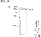
- chamfered parts 487a are formed at an end and on both circumferential sides of a second facing surface 482 (and a back surface 484).
- the end of the first segment conductor 470 has chamfered parts 477b formed also on both radial edges thereof.
- the end of the second segment conductor 480 has chamfered parts 487b formed also on both radial edges thereof.
- the first facing surface 472 indicates a surface of a first segment conductor end part 470b of the first segment conductor 470 that faces in the radial direction, the first segment conductor end part 470b having a thickness t12 smaller than a first segment conductor main body part 470a having a thickness t11.
- the second facing surface 482 indicates a surface of a second segment conductor end part 480b of the second segment conductor 480 that faces in the radial direction, the second segment conductor end part 480b having a thickness t14 smaller than a second segment conductor main body part 480a having a thickness t13.
- a joint portion 490 is formed.
- a joint portion insulating member 492 for insulating the joint portion 490 is provided between a back surface 474 of a first segment conductor 470 and a back surface 484 of a second segment conductor 480.
Landscapes
- Engineering & Computer Science (AREA)
- Power Engineering (AREA)
- Manufacturing & Machinery (AREA)
- Windings For Motors And Generators (AREA)
- Manufacture Of Motors, Generators (AREA)
- Insulation, Fastening Of Motor, Generator Windings (AREA)
Abstract
Description
- The present invention relates to an armature.
- Conventionally, there is known an armature including an armature core provided with a plurality of slots extending in a central axis line direction. Such an armature is disclosed in, for example,
JP 2006-141076 A -
JP 2006-141076 A - In addition, in
JP 2006-141076 A - Patent Literature 1:
JP 2006-141076 A - However, in
JP 2006-141076 A - The invention is made to solve a problem such as that described above, and provides an armature capable of preventing a shortage of a joint area.
- To provide the above-described armature, an armature according to one aspect of the invention includes: an armature core provided with a plurality of slots extending in a central axis line direction; and a coil part having a plurality of segment conductors whose facing surfaces are joined together, the plurality of segment conductors being disposed so as to face the central axis line direction, and the plurality of segment conductors include a first segment conductor disposed on one side in the central axis line direction of the armature core; and a second segment conductor disposed on an other side in the central axis line direction of the armature core, the facing surfaces provided at an end part of the first segment conductor and an end part of the second segment conductor are disposed so as to overlap each other as viewed in a radial direction, the facing surfaces being portions where the first segment conductor and the second segment conductor are joined together, and the end part of at least one of the first segment conductor and the second segment conductor is provided with chamfered parts at edge parts on both circumferential sides of the end part.
- In the armature according to the one aspect of the invention, as described above, facing surfaces which are portions where a first segment conductor and a second segment conductor are joined together and which are provided at an end part of the first segment conductor and an end part of the second segment conductor are disposed so as to overlap each other as viewed in the radial direction, and the end part of at least one of the first segment conductor and the second segment conductor is provided with chamfered parts at edge parts on both circumferential sides thereof. By this, since the facing surface of the first segment conductor and the facing surface of the second segment conductor are provided so as to overlap each other as viewed in the radial direction, even when chamfered parts are provided at the end part of at least one of the first segment conductor and the second segment conductor, the amount of reduction in the area of the facing surface can be reduced. As a result, a shortage of a joint area can be prevented.
- According to the present invention, as described above, a shortage of a joint area can be prevented.
-
-
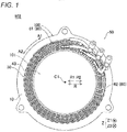
FIG. 1 is a plan view showing a configuration of a stator (rotating electrical machine) according to one embodiment. -
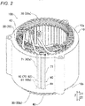
FIG. 2 is a perspective view showing a configuration of the stator according to one embodiment. -
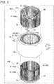
FIG. 3 is an exploded perspective view of the stator according to one embodiment. -
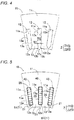
FIG. 4 is a plan view showing a configuration of a stator core according to one embodiment. -
FIG. 5 is a cross-sectional view showing a configuration of insulating members according to one embodiment. -
FIG. 6 is a circuit diagram showing a connection configuration of a coil part according to one embodiment. -
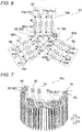
FIG. 7 is a perspective view showing a part of a first coil assembly according to one embodiment. -
FIG. 8 is a transverse cross-sectional view showing a configuration of a segment conductor according to one embodiment, andFIG. 8A is a diagram showing an insulating film andFIG. 8B is a diagram showing an insulating member. -
FIG. 9 is a diagram (1) showing a configuration of general conductors according to one embodiment, andFIG. 9A is a front view andFIG. 9B is a side view. -
FIG. 10 is a diagram (1) of chamfered parts as viewed in a circumferential direction according to one embodiment. -
FIG. 11 is a diagram showing a configuration of a first facing surface of a first segment conductor according to one embodiment. -
FIG. 12 is a diagram showing a configuration of a second facing surface of a second segment conductor according to one embodiment. -
FIG. 13 is a diagram (2) of chamfered parts as viewed in the circumferential direction according to one embodiment. -
FIG. 14 is a diagram (side view) showing a manufacturing device according to one embodiment. -
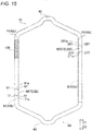
FIG. 15 is a diagram (2) showing a configuration of general conductors according to one embodiment. -
FIG. 16 is a diagram of chamfered parts as viewed in a radial direction according to one embodiment. -
FIG. 17 is a diagram (top view) showing the manufacturing device according to one embodiment. -
FIG. 18 is a flowchart showing steps of manufacturing the stator according to one embodiment. -
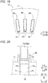
FIG. 19 is a cross-sectional view for describing a step of disposing insulating members in slots according to one embodiment. -
FIG. 20 is a diagram showing a state in which a segment conductor is inserted into a slot having an insulating member disposed therein, according to one embodiment. -
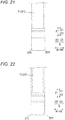
FIG. 21 is a diagram showing chamfered parts according to a first variant. -
FIG. 22 is a diagram (diagram as viewed in the radial direction) showing chamfered parts according to a second variant. -
FIG. 23 is a diagram (diagram as viewed in the circumferential direction) showing the chamfered parts according to the second variant. -
FIG. 24 is a diagram of first segment conductors and second segment conductors which are joined together as viewed in the circumferential direction, according to a third variant. -
FIG. 25 is a partial enlarged view ofFIG. 24 . -
FIG. 26 is a diagram of a first segment conductor as viewed in the radial direction according to the third variant. -
FIG. 27 is a diagram of a second segment conductor as viewed in the radial direction according to the third variant. - The present embodiment of the present invention will be described below based on the drawings.
- With reference to
FIGS. 1 to 16 , a structure of astator 100 according to the present embodiment will be described. Thestator 100 has an annular shape having a central axis line C1 at the center thereof. Note that thestator 100 is an example of an "armature" in the claims. - In the specification of this application, an "axial direction (central axis line direction)" indicates, as shown in
FIG. 1 , a direction (Z-direction) along the central axis line C1 of the stator 100 (a rotation axis line of a rotor 101). In addition, a "circumferential direction" indicates a circumferential direction (an A1-direction and an A2-direction) of thestator 100. In addition, a "radial direction" indicates a radial direction (R-direction) of thestator 100. In addition, a "radial inner side" indicates a direction (R1-direction) going toward the central axis line C1 of thestator 100 in the radial direction. In addition, a "radial outer side" indicates a direction (R2-direction) going toward the outside of thestator 100 in the radial direction. - The
stator 100 together with therotor 101 forms a part of a rotatingelectrical machine 102. The rotatingelectrical machine 102 is constructed as, for example, a motor, a generator, or a motor-generator. As shown inFIG. 1 , thestator 100 is disposed on the radial outer side of therotor 101 having permanent magnets (not shown) provided thereon. Namely, in the present embodiment, thestator 100 forms a part of the inner-rotor rotatingelectrical machine 102. - As shown in
FIG. 2 , thestator 100 includes astator core 10, insulatingmembers 20, and acoil part 30. In addition, as shown inFIG. 3 , thecoil part 30 includes afirst coil assembly 30a and asecond coil assembly 30b. In addition, thecoil part 30 includes a plurality ofsegment conductors 40. Note that thestator core 10 is an example of an "armature core" in the claims. - The
stator core 10 has a cylindrical shape having the central axis line C1 (seeFIG. 1 ) as its central axis. In addition, thestator core 10 is constructed by, for example, stacking a plurality of electromagnetic steel sheets (e.g., silicon steel sheets) in the axial direction. As shown inFIG. 4 , thestator core 10 is provided with aback yoke 11 having an annular shape as viewed in the axial direction; and a plurality ofslots 12 provided on the radial inner side of theback yoke 11 and extending in the axial direction. Thestator core 10 is provided with a plurality ofteeth 13 on both circumferential sides of theslots 12. - Each
slot 12 is a portion surrounded by awall part 11a of theback yoke 11 that is provided more on the radial outer side than a firstother end surface 73 which will be described later, and circumferential side surfaces 13a of twoteeth 13. Theslot 12 is provided with anopening part 12a that opens on the radial inner side. In addition, theslot 12 opens on both axial sides. Eachtooth 13 is formed so as to protrude from theback yoke 11 toward the radial inner side, and has projectingparts 13b formed at an end part on the radial inner side thereof, the projectingparts 13b formingopening parts 12a ofslots 12. - Each
opening part 12a has an opening width W1 in the circumferential direction. Here, the opening width W1 corresponds to a distance between end parts of projectingparts 13b ofteeth 13. In addition, a width W2 of a portion of aslot 12 where thecoil part 30 and an insulatingmember 20 are disposed is larger than the opening width W1. Namely, theslot 12 is constructed as a semi-open slot. Here, the width W2 corresponds to a distance between circumferential side surfaces 13a ofteeth 13 disposed on both circumferential sides of theslot 12. In addition, the width W2 of theslot 12 is substantially constant in the radial direction. - As shown in
FIG. 5 , each insulatingmember 20 is disposed betweenteeth 13 andsegment conductors 40. The insulatingmember 20 includes a joint-portion covering part 21. The joint-portion covering part 21 is configured to cover at least the radial inner side of a joint portion 90 (described later) of one of a plurality of parallelly and radially arrangedsegment conductors 40 that is arranged on a side closest to anopening part 12a of aslot 12. - Specifically, the insulating
members 20 are made of, for example, sheet-like insulating members such as aramid paper and polymer films, and have a function of ensuring insulation between the segment conductors 40 (the coil part 30) and thestator core 10. Each insulatingmember 20 is disposed betweensegment conductors 40 and circumferential side surfaces 13a ofteeth 13 and between one of the plurality ofsegment conductors 40 that is disposed on the radially outermost side and awall part 11a. In addition, as shown inFIG. 3 , each insulatingmember 20 includes collar parts 22 (cuff parts) formed so as to protrude from aslot 12 toward the axial outer side on both axial sides and to be folded back. - Each insulating
member 20 is disposed so as to entirely cover the circumference of a plurality of parallelly and radially arrangedsegment conductors 40 as viewed in an arrow "Z2" direction. In other words, both circumferential sides and both radial sides ofleg parts segment conductors 40 are covered by the insulatingmember 20. By this, it becomes possible to ensure insulation between thejoint portions 90 and thestator core 10 by the insulatingmember 20. - As shown in
FIGS. 2 and3 , thecoil part 30 is formed by axially combining and joining together thefirst coil assembly 30a provided on one axial side (an arrow "Z1" direction side) and thesecond coil assembly 30b provided on the other axial side (an arrow "Z2" direction side). Thefirst coil assembly 30a and thesecond coil assembly 30b each are formed in annular shape having the same central axis line C1 as the stator core 10 (seeFIG. 1 ) at the center thereof. - The
coil part 30 is constructed as, for example, wave-winding coils. In addition, thecoil part 30 is constructed as 8-turn coils. Namely, as shown inFIG. 5 , thecoil part 30 is configured such that eightsegment conductors 40 are parallelly and radially arranged in eachslot 12. Thecoil part 30 is configured such that by supplying three-phase alternating-current power to thecoil part 30 from a power supply part (not shown), while current moves back and forth in the axial direction and flows in the circumferential direction, a magnetic flux is generated. - As shown in
FIG. 6 , thecoil part 30 is connected using three-phase "Y" connection. Namely, thecoil part 30 includes aU-phase coil part 30U, a V-phase coil part 30V, and a W-phase coil part 30W. For example, thecoil part 30 is provided with a plurality of neutral points N. Specifically, thecoil part 30 is four parallel-connected (star-connected). Namely, theU-phase coil part 30U is provided with four neutral-point connection end parts NtU and four power-line connection end parts PtU. The V-phase coil part 30V is provided with four neutral-point connection end parts NtV and four power-line connection end parts PtV. The W-phase coil part 30W is provided with four neutral-point connection end parts NtW and four power-line connection end parts PtW. Note that in the following description when the neutral-point connection end parts and the power-line connection end parts for the U-phase, the V-phase, and the W-phase are not particularly distinguished from each other, they are simply described as "neutral-point connection end parts Nt" and "power-line connection end parts Pt". - As shown in
FIG. 7 , thefirst coil assembly 30a includes a plurality of (e.g., three) segment conductors for power-line connection 50 (hereinafter, referred to as "power conductors 50") which aresegment conductors 40; a plurality of (e.g., two) segment conductors for neutral point connection 60 (hereinafter, referred to as "neutral point conductors 60") which aresegment conductors 40; and a plurality ofgeneral conductors 41 which are conductors (general segment conductors 40) different than thepower conductors 50 and theneutral point conductors 60 among the plurality ofsegment conductors 40 and which form thecoil part 30. - As shown in
FIG. 3 , thesecond coil assembly 30b includes a plurality ofgeneral conductors 41. Preferably, thesecond coil assembly 30b includes only a plurality ofgeneral conductors 41, and all of thepower conductors 50 and theneutral point conductors 60 provided in thestator 100 are provided in thefirst coil assembly 30a. - As shown in
FIG. 8(a) , eachsegment conductor 40 is constructed as a rectangular conducting wire whose transverse section has a substantially rectangular shape. Aconductor surface 40b of thesegment conductor 40 is provided with an insulatingfilm 40a having a thickness t1. The thickness t1 of the insulatingfilm 40a is set to such a thickness, for example, that allows to ensure phase-to-phase insulation performance (insulation between coil end parts 43). In addition, a conductormain body 40c of thesegment conductor 40 is made of, for example, a metal material (conductive material) such as copper or aluminum. Note that althoughFIG. 8 shows a magnitude relationship between thicknesses, etc., in an exaggerated manner for the sake of description, the configuration is not limited to the example shown in the drawing. - As shown in
FIG. 9 , asegment conductor 40 includesleg parts slots 12; and acoil end part 43. Theleg parts slots 12 from an axial location of anend surface stator core 10, and thecoil end part 43 indicates a portion that is formed so as to continue to theleg parts end surface stator core 10. In addition, thecoil end part 43 has a bent shape that bends in the axial direction. In addition, thecoil end part 43 has acrank portion 43a formed in crank shape that radially bends in a stepwise manner for an amount corresponding to the width of asingle segment conductor 40 as viewed in the axial direction. That is, the radial width of thecrank portion 43a is double the width of asingle segment conductor 40. - As shown in
FIG. 9 , ageneral conductor 41 includes a pair ofleg parts different slots 12; and acoil end part 43 that connects the pair ofleg parts general conductor 41 has a substantially U-shape or a substantially J-shape as viewed from the radial inner side. Theleg parts leg parts power conductors 50 andleg parts neutral point conductors 60 are configured in the same manner as theleg parts general conductors 41, and thus, description thereof is omitted. - Here, the coil pitch of the
general conductors 41 is six. Namely, a pair ofleg parts slots 12. Namely, five slots are provided between aslot 12 in which aleg part 42a of ageneral conductor 41 is disposed and aslot 12 in which aleg part 42b is disposed. - In addition, the pair of
leg parts leg part 42a is larger than an axial length L2 of theleg part 42b. Note that the axial length L1 (L2) of theleg part 42a (42b) indicates a length from an end 75 (85) to an axial location corresponding to theend surface 10a (10b) in the axial direction of thestator core 10. In addition, the axial lengths L1 and L2 are smaller than an axial length L3 of thestator core 10. Note that the axial length L3 of thestator core 10 indicates an axial distance (space) between the end surfaces 10a and 10b. For example, the axial length L1 is larger than one-half of the axial length L3, and the axial length L2 is smaller than one-half of the axial length L3. - In addition, the plurality of
general conductors 41 include one-sidegeneral conductors 41a that are disposed on one axial side (the arrow "Z1" direction side) of thestator core 10 and included in thefirst coil assembly 30a; and other-sidegeneral conductors 41b that are disposed on the other axial side (the arrow "Z2" direction side) of thestator core 10 and included in thesecond coil assembly 30b. - As shown in
FIG. 10 , in aslot 12 of thestator core 10, afirst leg part 71 which is aleg part 42a of afirst segment conductor 70 which is one of a plurality ofsegment conductors 40 that is included in thefirst coil assembly 30a and asecond leg part 81 which is aleg part 42b of asecond segment conductor 80 which is asegment conductor 40 included in thesecond coil assembly 30b and axially facing thefirst segment conductor 70 are joined together at ajoint portion 90. - Likewise, as shown in
FIG. 13 , in theslot 12 of thestator core 10, afirst leg part 71 which is aleg part 42b of afirst segment conductor 70 which is asegment conductor 40 included in thefirst coil assembly 30a and asecond leg part 81 which is aleg part 42a of asecond segment conductor 80 which is asegment conductor 40 included in thesecond coil assembly 30b are joined together at ajoint portion 90. - As shown in
FIGS. 10 and11 , thefirst leg part 71 includes a first facingsurface 72 facing the radial outer side (an arrow "R2" direction side) and facing thesecond leg part 81. In addition, thefirst leg part 71 includes a first oneend surface 74 provided on one radial side which is the same side as the first facingsurface 72; and a firstother end surface 73 provided on the other radial side. - In addition, as shown in
FIG. 12 , thesecond leg part 81 includes a second facingsurface 82 facing the radial inner side (an arrow "R1" direction side) and facing the first facingsurface 72. In addition, thesecond leg part 81 includes a second oneend surface 84 provided on one radial side which is an opposite side to a secondjoint surface 82a; and a secondother end surface 83 provided on the other radial side. Note that the first facingsurface 72 and the second facingsurface 82 are an example of "facing surfaces" in the claims. - The first
other end surface 73 of thefirst segment conductor 70 is disposed so as to be offset (to protrude) more radially (R1-direction side) than the secondother end surface 83 of thesecond segment conductor 80. In addition, the second oneend surface 84 of thesecond segment conductor 80 is disposed so as to be offset (to protrude) more radially (R2-direction side) than the first oneend surface 74 of thefirst segment conductor 70. - Here, the
joint portion 90 is a portion of thecoil part 30 shown inFIG. 10 , and is a portion including the first facingsurface 72 and the second facingsurface 82 and including a portion from anend 75 of thefirst leg part 71 to aboundary point 76 between the first facingsurface 72 and the first oneend surface 74 and a portion from anend 85 of thesecond leg part 81 to aboundary point 86 between the second facingsurface 82 and the secondother end surface 83. - An
other step part 111 is formed at a portion between theend 75 of thefirst leg part 71 and theboundary point 86 of thesecond leg part 81, which is a boundary portion between the firstother end surface 73 and the secondother end surface 83. In addition, a onestep part 112 is formed at a portion between theboundary point 76 of thefirst leg part 71 and theend 85 of thesecond leg part 81, which is a boundary portion between the first oneend surface 74 and the second oneend surface 84. Specifically, at theother step part 111, a step is formed so as to be recessed toward the inner sides of thesegment conductors 40 in a direction from the firstother end surface 73 to the secondother end surface 83. In addition, at the onestep part 112, a step is formed so as to be recessed toward the inner sides of thesegment conductors 40 in a direction from the second oneend surface 84 to the first oneend surface 74. - In addition, a first displacement width d1 which is a displacement width between a radial location P1 of the first
other end surface 73 and a radial location P2 of the secondother end surface 83 is, for example, greater than the thickness t1 of the insulatingfilm 40a of thesegment conductor 40. - As shown in
FIG. 14 , a plurality of (e.g., eight)first leg parts 71 and a plurality of (e.g., eight)second leg parts 81 are disposed in aslot 12 so as to be radially adjacent to each other. Namely, the plurality offirst leg parts 71 are parallelly and radially arranged and the plurality ofsecond leg parts 81 are parallelly and radially arranged. - In the
slot 12, one of first facing surfaces 72 of the plurality offirst leg parts 71 is disposed at a different axial location than another first facingsurface 272 radially adjacent thereto which will be described later. In addition, in theslot 12, one of second facing surfaces 82 of the plurality ofsecond leg parts 81 is disposed at a different axial location than another second facingsurface 282 radially adjacent thereto which will be described later. Namely, an axial location P11 of ajoint portion 90 including a first facingsurface 272 and a second facingsurface 282 is a different location than an axial location P12 of ajoint portion 90 including another first facingsurface 72 and another second facingsurface 82 which are radially adjacent to the first facingsurface 272 and the second facingsurface 282. Note that the first facingsurface 272 and the second facingsurface 282 are an example of "facing surfaces" in the claims. - In other words, in the axial locations P11 and P12, the
first leg parts 71 and thesecond leg parts 81 are staggered in the radial direction. - As shown in
FIG. 11 , the first facingsurface 72 of thefirst leg part 71 includes a firstjoint surface 72a which is inclined in an arrow "E11" direction; a first reverse inclinedsurface 72b which is inclined in an arrow "E12" direction; and a first separated and facingsurface 72c which is inclined in an arrow "E13" direction. In addition, as shown inFIG. 12 , the second facingsurface 82 of thesecond leg part 81 includes a secondjoint surface 82a which is inclined in an arrow "E21" direction; a second reverse inclinedsurface 82b which is inclined in an arrow "E22" direction; and a second separated and facingsurface 82c which is inclined in an arrow "E23" direction. A specific description will be made below. - As shown in
FIG. 10 , the first facingsurface 72 of thefirst leg part 71 and the second facingsurface 82 of thesecond leg part 81 are formed so as to be inclined with respect to the axial direction. Specifically, the first facingsurface 72 is constructed as an end surface that is inclined with respect to the axial direction in an arrow "E1" direction from theend 75 of thefirst leg part 71. In addition, the first facingsurface 72 is not provided with an insulatingfilm 40a. The second facingsurface 82 is constructed as an end surface that is inclined in an arrow "E2" direction from theend 85 of thesecond leg part 81. In addition, the second facingsurface 82 is not provided with an insulatingfilm 40a. Note that the arrow "E1" direction indicates a direction going from theend 75 toward theboundary point 76 between the first facingsurface 72 and the first oneend surface 74. Note also that the arrow "E2" direction indicates a direction going from theend 85 toward theboundary point 86 between the second facingsurface 82 and the secondother end surface 83. - The first facing
surface 72 and the second facingsurface 82 each are formed such that its radial cross-section has an S-shape. The first facingsurface 72 having an S-shape (uneven shape) and the second facingsurface 82 having an S-shape (uneven shape) are disposed in aslot 12, with the first facingsurface 72 and the second facingsurface 82 being radially engaged with each other. - In addition, a part of the first facing
surface 72 and a part of the second facingsurface 82 are joined together with ajoint material 130. Specifically, the first facingsurface 72 includes the firstjoint surface 72a which is joined to the second facingsurface 82; and the first reverse inclinedsurface 72b which is formed continuously with the firstjoint surface 72a and which is inclined in an opposite direction (the arrow "E12" direction) to a direction in which the firstjoint surface 72a is inclined (the arrow "E11" direction) with respect to the axial direction (an axis parallel to the central axis line C1). In addition, the firstjoint surface 72a and the first reverse inclinedsurface 72b each are formed as a substantially flat surface, and the firstjoint surface 72a and the first reverse inclinedsurface 72b form a bent shape. In addition, the second facingsurface 82 includes the secondjoint surface 82a which is joined to the firstjoint surface 72a; and the second reverse inclinedsurface 82b which is formed continuously with the secondjoint surface 82a and which is inclined in an opposite direction (the arrow "E22" direction) to a direction in which the secondjoint surface 82a is inclined (the arrow "E21" direction) with respect to the axial direction. - The
joint material 130 is disposed between the firstjoint surface 72a and the secondjoint surface 82a, by which the firstjoint surface 72a and the secondjoint surface 82a are joined together and electrically connected to each other. Specifically, thejoint material 130 includes a conductive material such as silver or copper. Preferably, thejoint material 130 is a paste-like joint material (silver nanopaste) in which a solvent contains, as conductive particles, metal particles obtained by grinding silver into fine particles of a nanometer level. In addition, thejoint material 130 contains a component (resin component) that is volatilized when heated, and has a function of allowing the firstjoint surface 72a and the secondjoint surface 82a to come close to each other by a reduction in the volume of thejoint material 130 by heating the component that is volatilized. - As shown in
FIG. 10 , the first facingsurface 72 includes the first separated and facingsurface 72c which is formed continuously on an opposite side to the firstjoint surface 72a side of the first reverse inclinedsurface 72b and which is disposed so as to be separated from the second facingsurface 82. In addition, the second facingsurface 82 includes the second separated and facingsurface 82c which is formed continuously on an opposite side to the secondjoint surface 82a side of the second reverse inclinedsurface 82b and which is disposed so as to be separated from the first facingsurface 72. - Specifically, the first separated and facing
surface 72c is inclined in the arrow "E13" direction which is an axially (an axis parallel to the central axis line C1) opposite direction to the first reverse inclinedsurface 72b. In addition, the second separated and facingsurface 82c is inclined in the arrow "E23" direction which is an axially opposite direction (the axis parallel to the central axis line C1) to the second reverse inclinedsurface 82b. The second separated and facingsurface 82c is disposed so as to face the first separated and facingsurface 72c, and clearance CL is made between the first separated and facingsurface 72c and the second separated and facingsurface 82c. - In addition, the
end 75 of thefirst leg part 71 and theend 85 of thesecond leg part 81 are formed on flat planes orthogonal to each other in the axial direction. - Note that although
FIG. 10 shows that the end side of thefirst leg part 71 has a shape in which the end is thinner than the end side (end-thickening shape) of thesecond leg part 81, one side (theleg part 42a having the axial length L1) of thefirst leg part 71 has an end-thinning shape shown inFIG. 10 , and the other side (theleg part 42b having the axial length L2) of thefirst leg part 71 has an end-thickening shape shown inFIG. 13 . Likewise, theleg part 42a of the second leg part 81 (seeFIG. 13 ) has an end-thinning shape, and theleg part 42b of the second leg part 81 (seeFIG. 10 ) has an end-thickening shape. That is, thefirst segment conductor 70 and thesecond segment conductor 80 have substantially the same shape. - As shown in
FIG. 13 , in a portion where theleg part 42b of thefirst segment conductor 70 and theleg part 42a of thesecond segment conductor 80 are joined together, a firstjoint surface 272a included in a first facingsurface 272 of thefirst segment conductor 70 and a secondjoint surface 282a included in a second facingsurface 282 of thesecond segment conductor 80 are joined together. - Here, in the present embodiment, as shown in
FIG. 15 , a first facingsurface 72 of afirst segment conductor 70 and a second facingsurface 82 of asecond segment conductor 80 which are provided at anend part 71a of thefirst segment conductor 70 and anend part 81a of thesecond segment conductor 80 are disposed so as to overlap each other as viewed in the radial direction. Specifically, substantially the entire first facingsurface 72 and substantially the entire second facingsurface 82 overlap each other as viewed in the radial direction. In other words, the first facingsurface 72 of thefirst segment conductor 70 and the second facingsurface 82 of thesecond segment conductor 80 are disposed so as to radially face each other. Theend part 71a of the first segment conductor 70 (leg part 42a) is provided withchamfered parts 77 atedge parts 71d on both circumferential sides thereof (as viewed in the radial direction). Likewise, theend part 81a of the second segment conductor 80 (leg part 42b) is provided withchamfered parts 87 atedge parts 81d on both circumferential sides thereof. Likewise, anend part 271a of the first segment conductor 70 (leg part 42b) is provided withchamfered parts 277 atedge parts 271d on both circumferential sides thereof. In addition, anend part 281a of the second segment conductor 80 (leg part 42a) is provided withchamfered parts 287 atedge parts 281d on both circumferential sides thereof. - A specific configuration of the chamfered
parts 77, the chamferedparts 277, the chamferedparts 87, and the chamferedparts 287 will be described below. Note that the chamferedparts 77, the chamferedparts 277, the chamferedparts 87, and the chamferedparts 287 have the same configuration and thus the chamferedparts 77 will be mainly described. - In the present embodiment, as shown in
FIG. 16 , chamferedparts 77 are provided on both circumferential sides of anend part 71a of afirst segment conductor 70 as viewed in the radial direction. Specifically, by chamfering two corner parts 71b of theend part 71a, chamferedparts 77 are formed. A total circumferential length L11 of the chamferedparts 77 provided on both circumferential sides of theend part 71a (double a circumferential length L13 of a single chamfered part 77) is smaller than a circumferential length L12 of aportion 71c of theend part 71a other than the chamferedparts 77. For example, the total length L11 is less than one-half of the length L12. - The chamfered
parts 77 are provided so as to intersect the central axis line direction at an angle θ1 of 45 degrees or more as viewed in the radial direction. In other words, the chamferedparts 77 are provided so as to intersect the circumferential direction at an angle of less than 45 degrees as viewed in the radial direction. Note that in the present embodiment the chamferedparts 77 intersect the central axis line direction at an angle θ1 of substantially 45 degrees. In addition, an angle θ2 formed by eachchamfered part 77 and theportion 71c of theend part 71a other than the chamferedparts 77 is an obtuse angle. - In addition, the chamfered
parts 77 are provided at a firstjoint surface 72a. That is, by chamfering parts (corner parts) of the firstjoint surface 72a, chamferedparts 77 are formed. Note that chamfered parts 287 (seeFIG. 13 ) are provided at a secondjoint surface 282a. In addition, chamferedparts 277 are provided at portions of afirst leg part 71 more on the end side than a firstjoint surface 272a. In addition, the chamferedparts 287 are provided at portions of asecond leg part 81 more on the end side than the secondjoint surface 282a. - In addition, as shown in
FIG. 10 , the firstjoint surface 72a and the secondjoint surface 82a both are provided so as to intersect the central axis line direction as viewed in the circumferential direction. The chamferedparts 77 are provided at the firstjoint surface 72a which is provided so as to intersect the central axis line direction. That is, the chamferedparts 77 are provided at theend part 71a of thefirst segment conductor 70 having an end-thinning shape. Likewise, as shown inFIG. 13 , the chamferedparts 287 are provided at the secondjoint surface 282a which is provided so as to intersect the central axis line direction. That is, the chamferedparts 287 are provided at theend part 281a of thesecond segment conductor 80 having an end-thinning shape. - In addition, as described above, as shown in
FIG. 5 , an insulatingmember 20 is disposed so as to cover inner surfaces on the circumferential side of a slot 12 (circumferential side surfaces 13a of teeth 13) and an inner surface on the radial side of the slot 12 (awall part 11a of the back yoke 11). As shown inFIG. 16 , the chamferedparts 77 are provided atedge parts 71d on the circumferential side of the first facing surface 72 (side surfaces on the circumferential side of theend part 71a) that face the insulatingmember 20. In addition, theedge parts 71d on the circumferential side of theend part 71a are disposed so as to be in contact with the insulatingmember 20 or to be slightly spaced apart from the insulatingmember 20. - As shown in
FIG. 16 , the chamferedparts 77 have a linear shape that linearly intersects a plane perpendicular to the central axis line direction. That is, the chamferedparts 77 have a flat plane shape. - Note that
corner parts 71e (fourcorner parts 71e) of theleg part 42a are chamfered, and the chamferedparts 77 are provided separately from this chamfering. - Likewise, as shown in
FIG. 15 , chamferedparts 87 are provided atedge parts 81d on both circumferential sides of anend part 81a of asecond segment conductor 80 as viewed in the radial direction (seeFIG. 12 ). In addition, the total circumferential length of the chamferedparts 87, the angle of inclination of the chamferedparts 87 with respect to the central axis line direction, and the shape (linear shape) of the chamferedparts 87 are the same as those of the above-describedchamfered parts 77. - In addition, chamfered
parts 277 are provided atedge parts 271d on both circumferential sides of anend part 271a (seeFIG. 13 ) of thefirst segment conductor 70 as viewed in the radial direction. In addition, the total circumferential length of the chamferedparts 277, the angle of inclination of the chamferedparts 277 with respect to the central axis line direction, and the shape (linear shape) of the chamferedparts 277 are the same as those of the above-describedchamfered parts 77. - In addition, chamfered
parts 287 are provided atedge parts 281d on both circumferential sides of anend part 281a (seeFIG. 13 ) of thesecond segment conductor 80 as viewed in the radial direction. In addition, the total circumferential length of the chamferedparts 287, the angle of inclination of the chamferedparts 287 with respect to the central axis line direction, and the shape (linear shape) of the chamferedparts 287 are the same as those of the above-describedchamfered parts 77. - In addition, in the present embodiment, as shown in
FIGS. 11 to 13 , the first facing surface 72 (272) of thefirst segment conductor 70 and the second facing surface 82 (282) of thesecond segment conductor 80 are provided so as to radially face each other and extend in the central axis line direction. The chamfered parts 77 (277, 87, 287) are provided at an end and edge parts on both circumferential sides of at least one (both in the present embodiment) of the first facing surface 72 (272) of thefirst segment conductor 70 and the second facing surface 82 (282) of thesecond segment conductor 80. - In addition, in the present embodiment, the
first segment conductor 70 includes the firstother end surface 73 provided on a radially opposite side to the first facing surface 72 (272) and provided so as to extend in the central axis line direction. In addition, thesecond segment conductor 80 includes the second oneend surface 84 provided on a radially opposite side to the second facing surface 82 (282) and provided so as to extend in the central axis line direction. The chamfered parts 77 (277, 87, 287) are provided at an end and edge parts on both circumferential sides of at least one (both in the present embodiment) of the firstother end surface 73 of thefirst segment conductor 70 and the second oneend surface 84 of thesecond segment conductor 80. Note that the firstother end surface 73 and the second oneend surface 84 are an example of "back surfaces" in the claims. - In addition, in the present embodiment, as shown in
FIGS. 11 and13 , a line segment L21 that forms an outer edge of the chamfered part 77 (277) provided at the first facing surface 72 (272) and a line segment L22 that forms an outer edge of the chamfered part 77 (277) provided at the firstother end surface 73 are provided on the same plane. Likewise, as shown inFIGS. 12 and13 , a line segment L23 that forms an outer edge of the chamfered part 87 (287) provided at the second facing surface 82 (282) and a line segment L24 that forms an outer edge of the chamfered part 87 (287) provided at the second oneend surface 84 are provided on the same plane. - In addition, as shown in
FIG. 8 , thecoil part 30 is provided with insulatingparts 120. One of a plurality of parallelly arrangedsegment conductors 40 has aninsulating part 120 provided at a portion of aconductor surface 40b thereof (seeFIG. 8(b) ) at an axial location corresponding to ajoint portion 90 ofother segment conductors 40 disposed so as to be radially adjacent to the one segment conductor 40 (hereinafter, thisjoint portion 90 is referred to as "adjacentjoint portion 90"), the insulatingpart 120 having a thickness t2 larger than a thickness t1 of an insulatingfilm 40a of the adjacentjoint portion 90. - Next, a
manufacturing device 200 for thestator 100 will be described. In the present embodiment, as shown inFIG. 14 , themanufacturing device 200 for thestator 100 includespressing jigs 201. Thepressing jigs 201 independently and radially press thefirst leg parts 71 of thefirst segment conductors 70 and thesecond leg parts 81 of thesecond segment conductors 80 which are disposed in the plurality ofslots 12, on a perslot 12 basis. Specifically, as shown inFIG. 17 , thepressing jigs 201 are disposed for the respective plurality ofslots 12 and configured to be radially movable. In addition, a plurality of (the same number as the number of the slots 12) pressingjigs 201 are provided for the respective plurality ofslots 12 and configured to be independently and radially movable on a perpressing jig 201 basis. - In addition, the
manufacturing device 200 for thestator 100 includesmovement mechanism parts 202 that allow thepressing jigs 201 to independently move on a perslot 12 basis. Themovement mechanism parts 202 are provided for the respective plurality of pressingjigs 201 and configured to be able to adjust the amount of radial movement on a perpressing jig 201 basis. Themovement mechanism parts 202 are composed of, for example, actuators. - In addition, as shown in
FIG. 14 , eachpressing jig 201 includescontact portions 201a that come into contact with afirst segment conductor 70 and asecond segment conductor 80. Eachcontact portion 201a has a shape whose corner parts are chamfered as viewed in the circumferential direction. - In addition, two
contact portions 201a are provided so as to protrude toward the radial outer side. The twocontact portions 201a are provided so as to be axially separated from each other. In addition, the twocontact portions 201a are configured to press locations corresponding tojoint portions 90 ofleg parts FIG. 14 ). By thepressing jig 201 pressing theleg parts joint portions 90 provided on a Z1-direction side and thejoint portions 90 provided on a Z2-direction side are simultaneously pressed by the twocontact portions 201a, respectively. - In addition, as shown in
FIG. 14 , themanufacturing device 200 for thestator 100 is provided with a push-outmember 203 and a holdingmember 204. The holdingmember 204 is configured to hold thepressing jig 201 and the push-outmember 203. In addition, the push-outmember 203 is formed, for example, in wedge shape (tapered shape) that becomes gradually thinner toward one axial side, and is configured such that axial movement of the push-outmember 203 presses (pushes out) thepressing jig 201 toward the radial outer side, and a pressing force is transmitted tosegment conductors 40 while allowing thepressing jig 201 to move toward the radial outer side. - Next, a method for manufacturing the
stator 100 according to the present embodiment will be described.FIG. 18 shows a flowchart for describing the method for manufacturing thestator 100. - First, at step S1, a plurality of
segment conductors 40 are prepared. Specifically, there areprepared power conductors 50 that form power-line connection end parts Pt for the respective phases of a Y-connectedcoil part 30;neutral point conductors 60 that form neutral point connection end parts Nt for the respective phases of thecoil part 30; andgeneral conductors 41 that form other portions of thecoil part 30. - For example, as shown in
FIG. 8(a) , an insulatingfilm 40a made of an insulating material such as polyimide is formed (coated) on arectangular conductor surface 40b made of a conductive material such as copper. Thereafter, conductors (rectangular conducting wires) having the insulatingfilms 40a formed thereon are shaped by a forming jig (not shown), by which general conductors 41 (seeFIG. 9 ), outside diameter side power conductors 52 and inside diameterside power conductors 53 for formingpower conductors 50, outside diameter sideneutral point conductors 61, and inside diameter sideneutral point conductors 62 are formed. - Specifically, as shown in
FIG. 9 , a pair ofleg parts coil end part 43 that connects the pair ofleg parts general conductor 41 is formed. Note that the formation ofpower conductors 50 andneutral point conductors 60 is omitted. - In addition, as shown in
FIG. 15 , chamferedparts 77 and chamferedparts 277 are formed in advance at first leg parts 71 (aleg part 42a and aleg part 42b) of afirst segment conductor 70. In addition, chamferedparts 87 and chamferedparts 287 are formed in advance at second leg parts 81 (aleg part 42a and aleg part 42b) of asecond segment conductor 80. - Then, at step S2 (see
FIG. 18 ), an insulatingpart 120 having a thickness t2 larger than a thickness t1 of the insulatingfilm 40a formed at ajoint portion 90 is provided on theconductor surface 40b of eachsegment conductor 40. - As shown in
FIG. 9 , by mounting an insulatingmember 121 on aleg part 42a having a longer axial length out of a pair ofleg parts part 120 is formed. Specifically, an insulatingmember 121 is mounted on each of theleg parts 42a of thegeneral conductors 41, theleg parts 42a of the outside diameter side power conductors 52, and theleg parts 42a of the outside diameter sideneutral point conductors 61. - Specifically, as shown in
FIG. 8(b) , a sheet-like insulatingmember 121 having a thickness t3 smaller than the thickness t1 is wound around aleg part 42a once or more and fixed. By this, when the number of windings is one, an insulatingpart 120 having a thickness t2 (= t1 + t3) larger than the thickness t1 is formed on theleg part 42a. - At step S3 (see
FIG. 18 ), as shown inFIG. 3 , afirst coil assembly 30a and asecond coil assembly 30b each having an annular shape and including a plurality ofsegment conductors 40 are formed. - As shown in
FIG. 3 , afirst coil assembly 30a and asecond coil assembly 30b each having an annular shape and including a plurality ofsegment conductors 40 are formed such that the insulatingpart 120 of onesegment conductor 40 is located in a position radially adjacent to ajoint portion 90 ofother segment conductors 40 disposed so as to be radially adjacent to the onesegment conductor 40. Note that althoughFIG. 3 only shows some (two) of the plurality of insulatingparts 120 by hatching for the sake of description, in the present embodiment, allleg parts 42a are provided with the insulatingparts 120. - Specifically, as shown in
FIG. 14 , in thefirst coil assembly 30a and thesecond coil assembly 30b, thesegment conductors 40 are formed such that a plurality of (e.g., eight)segment conductors 40 are parallelly and radially arranged, and such a number ofsegment conductors 40 that is equal to the number of theslots 12 are parallelly and circumferentially arranged. At this time, thefirst coil assembly 30a and thesecond coil assembly 30b are formed such that the insulatingpart 120 of one of the plurality of parallelly arrangedsegment conductors 40 is located in an axial position corresponding to ajoint portion 90 ofother segment conductors 40 disposed so as to be radially adjacent to the onesegment conductor 40. - At step S4 (see
FIG. 18 ), as shown inFIG. 19 , an insulatingmember 20 is disposed in each of the plurality ofslots 12. The insulatingmember 20 is disposed so as to be exposed or open on both axial sides and closed on the radial inner side. In addition, as shown inFIG. 3 , the disposed insulatingmember 20 is held in theslot 12 bycollar parts 22 on both axial sides. - At step S5 (see
FIG. 18 ), as shown inFIG. 3 , the plurality ofsegment conductors 40 are disposed in the plurality ofslots 12. Specifically, thefirst coil assembly 30a and thesecond coil assembly 30b are allowed to axially move relative to each other toward the plurality ofslots 12, by which each of theleg parts first coil assembly 30a and thesecond coil assembly 30b is disposed in one of the plurality ofslots 12. For example, thefirst coil assembly 30a is allowed to move in parallel (linearly move) to thestator core 10 in the arrow "Z2" direction and thesecond coil assembly 30b is allowed to move in parallel (linearly move) to thestator core 10 in the arrow "Z1" direction, by which each of theleg parts slots 12 having the insulatingmembers 20 disposed therein). - Here, as shown in
FIG. 20 , since aleg part 42a of afirst segment conductor 70 is provided withchamfered parts 77, when theleg part 42a is inserted into a slot 12 (in space enclosed by an insulating member 20), an end part (anend part 71a) of theleg part 42a can be prevented from getting stuck in corner parts of the slot 12 (corner parts of teeth 13). Likewise, since aleg part 42b of thefirst segment conductor 70 is provided withchamfered parts 277, when theleg part 42b is inserted into aslot 12, anend part 71a of theleg part 42b can be prevented from getting stuck in corner parts of theslot 12. Likewise, sinceleg parts second segment conductor 80 are provided withchamfered parts end parts slots 12. In addition, the insulatingmembers 20 can be prevented from getting damaged by the corner parts of theleg parts 42a and theleg parts 42b inserted in the slots 12 (in pieces of space enclosed by the insulating members 20). - In addition, as shown in
FIG. 14 , by disposing thefirst coil assembly 30a and thesecond coil assembly 30b in theslots 12, the plurality ofsegment conductors 40 are disposed in theslots 12 such that the insulatingpart 120 of one of a plurality of parallelly and radially arrangedsegment conductors 40 is located in an axial position corresponding to ajoint portion 90 disposed so as to be radially adjacent to the insulatingpart 120. - At step S6 (see
FIG. 18 ), as shown inFIG. 14 , thefirst leg parts 71 of thefirst segment conductors 70 and thesecond leg parts 81 of thesecond segment conductors 80 that axially face thefirst segment conductors 70 are radially pressed (pressurized) on a perslot 12 basis, by which thefirst leg parts 71 and thesecond leg parts 81 are joined together in theslot 12. - Note that by heating at least a
joint material 130 by a heating device (not shown) whileleg parts pressing jig 201, at least a part of a first facingsurface 72 and at least a part of a second facingsurface 82 are joined together, forming ajoint portion 90. Specifically, a firstjoint surface 72a (seeFIG. 10 ) and a secondjoint surface 82a are joined together. In addition, a firstjoint surface 272a (seeFIG. 13 ) and a secondjoint surface 282a are joined together. - Then, in one
slot 12,first leg parts 71 of apower conductor 50 and aneutral point conductor 60 andsecond leg parts 81 which are either one ofleg parts general conductors 41 are joined together, and in anotherslot 12,second leg parts 81 which are the other one of theleg parts general conductors 41 andfirst leg parts 71 ofgeneral conductors 41 are joined together. As a result, a wave-shapedcoil part 30 is formed. - As shown in
FIG. 14 , a portion where afirst leg part 71 and asecond leg part 81 are joined together serves as an electrically joinedjoint portion 90. By this, an insulatingpart 120 is disposed at a location (axial location) radially adjacent to thejoint portion 90. In addition, an axial location P11 of ajoint portion 90 is a different location than an axial location P12 of ajoint portion 90 ofsegment conductors 40 radially adjacent thereto. - In addition, the
first leg parts 71 and thesecond leg parts 81 together with the insulatingmembers 20 whose radial inner sides are closed are pressed by thepressing jigs 201 from the radial inner side. Thereafter, as shown inFIG. 2 , astator 100 is completed. Note that as shown inFIG. 1 , by combining thestator 100 with arotor 101, a rotatingelectrical machine 102 is manufactured. - In the above-described present embodiment, the following advantageous effects can be obtained.
- In the present embodiment, as described above, facing surfaces (72, 82, 272, 282) which are portions where a first segment conductor (70) and a second segment conductor (80) are joined together and which are provided at an end part (71a, 271a) of the first segment conductor (70) and an end part (81a, 281a) of the second segment conductor (80) are disposed so as to overlap each other as viewed in the radial direction, and the end part (71a, 271a) of the first segment conductor (70) and the end part (81a, 281a) of the second segment conductor (80) each are provided with chamfered parts (77, 87, 277, 287) at edge parts on both circumferential sides thereof (71d, 81d, 271d, 281d). By this, since the facing surface (72, 272) of the first segment conductor (70) and the facing surface (82, 282) of the second segment conductor (80) are provided so as to overlap each other as viewed in the radial direction, even when chamfered parts (77, 87, 277, 287) are provided at the end part of at least one of the first segment conductor (70) and the second segment conductor (80), the amount of reduction in the area of the facing surface (72, 82, 272, 282) can be reduced. As a result, a shortage of a joint area can be prevented.
- In addition, since the facing surfaces (72, 82, 272, 282) provided at the end part (71a, 271a) of the first segment conductor (70) and the end part (81a, 281a) of the second segment conductor (80) are disposed so as to overlap each other as viewed in the radial direction, a joint material (130) disposed on the facing surfaces (72, 82, 272, 282) can be prevented from flowing in the radial direction. As a result, leg parts (42a, 42b) can be appropriately bonded together. In addition, since the end part (71a, 271a) of the first segment conductor (70) and the end part (81a, 281a) of the second segment conductor (80) each are provided with the chamfered parts (77, 87, 277, 287) at edge parts on both circumferential sides thereof (71d, 81d, 271d, 281d), when the first segment conductor (70) and the second segment conductor (80) are inserted into a slot (12), at least one of the first segment conductor (70) and the second segment conductor (80) can be smoothly inserted into the slot (12). By these configurations, the leg parts (42a, 42b) can be appropriately bonded together while the insertion properties of the leg parts (42a, 42b) into the slot (12) improve. In addition, since the end part (71a, 271a) of the first segment conductor (70) and the end part (81a, 281a) of the second segment conductor (80) are provided with the chamfered parts (77, 87, 277, 287), an insulating member (20) disposed in the slot (12) can be prevented from getting damaged by the first segment conductor (70) and the second segment conductor (80).
- In addition, in the present embodiment, as described above, a total circumferential length (L11) of the chamfered parts (77, 87, 277, 287) provided on both circumferential sides of the end part (71a, 81a, 271a, 281a) is smaller than a circumferential length (L12) of a portion (71C) of the end part (71a, 81a, 271a, 281a) other than the chamfered parts (77, 87, 277, 287). By such a configuration, unlike a case in which the total circumferential length (L11) of the chamfered parts (77, 87, 277, 287) is greater than or equal to the circumferential length (L12) of the portion (71C) of the end part (71a, 81a, 271a, 281a) other than the chamfered parts (77, 87, 277, 287), the size of the chamfered parts (77, 87, 277, 287) is relatively small, and thus, a reduction in the size of the end part (71a, 81a, 271a, 281a) where the facing surface (72, 82, 272, 282) is provided can be prevented. By this, joint strength between the leg parts (42a, 42b) can be ensured.
- In addition, in the present embodiment, as described above, the chamfered parts (77, 87, 277, 287) are provided so as to intersect the central axis line direction at an angle of 45 degrees or more as viewed in the radial direction. By such a configuration, since the size of portions of the end part (71a, 81a, 271a, 281a) that are cut away as a result of the formation of the chamfered parts (77, 87, 277, 287) can be made relatively small, a reduction in the size of the end part (71a, 81a, 271a, 281a) where the facing surface (72, 82, 272, 282) is provided can be effectively prevented.
- In addition, in the present embodiment, as described above, the chamfered parts (77, 287) are provided at a first joint surface (72a) and a second joint surface (282a). By such a configuration, since the chamfered parts (77, 287) are provided at the first joint surface (72a) (the second joint surface (282a)) that comes into contact with corners of a slot (12) (corners of teeth (13)) at a relatively early stage upon inserting the first segment conductor (70) (the second segment conductor (80)) into the slot (12), the first segment conductor (70) (the second segment conductor (80)) can be more smoothly inserted into the slot (12).
- In addition, in the present embodiment, as described above, the chamfered parts (77, 287) are provided at the first joint surface (72a) and the second joint surface (282a) which are provided so as to intersect the central axis line direction. By such a configuration, compared to a case in which the first joint surface (72a) and the second joint surface (282a) are provided along the central axis line direction, the areas of the first joint surface (72a) and the second joint surface (282a) can be increased. Therefore, by providing the chamfered parts (77, 287) at the first joint surface (72a) and the second joint surface (282a) which are provided so as to intersect the central axis line direction, the influence of a reduction in joint area caused by the formation of the chamfered parts (77, 287) can be reduced.
- In addition, in the present embodiment, as described above, the chamfered parts (77, 87, 277, 287) are provided at both of the end parts (71a, 271a) of the first segment conductor (70) and the end parts (81a, 281a) of the second segment conductor (80). By such a configuration, both the first segment conductor (70) and the second segment conductor (80) can be smoothly inserted into slots (12), and damage to insulating members (20) by both the first segment conductor (70) and the second segment conductor (80) can be prevented.
- In addition, in the present embodiment, as described above, the chamfered parts (77, 87, 277, 287) are provided at the edge parts (71d, 81d, 271d, 281d) on the circumferential side of the facing surface (72, 82, 272, 282) that face an insulating member (20). By such a configuration, since the chamfered parts (77, 87, 277, 287) are provided at the edge parts (71d, 81d, 271d, 281d) of the facing surface (72, 82, 272, 282) that face the insulating member (20), damage to the insulating member (20) can be effectively prevented.
- In addition, in the present embodiment, as described above, the chamfered parts (77, 87, 277, 287) have a linear shape that linearly intersects the circumferential direction as viewed in the radial direction. By such a configuration, since the chamfered parts (77, 87, 277, 287) have a relatively simple shape, the chamfered parts (77, 87, 277, 287) can be easily formed.
- In addition, in the present embodiment, as described above, a first leg part (71) of the first segment conductor (70) and a second leg part (81) of the second segment conductor (80) are joined together in a slot (12). By such a configuration, since the end part (71a, 271a) of the first segment conductor (70) and the end part (81a, 281a) of the second segment conductor (80) each are provided with the chamfered parts (77, 87, 277, 287) at edge parts on both circumferential sides thereof (71d, 81d, 271d, 281d), the first leg part (71) and the second leg part (81) can be smoothly inserted into the slot (12) and joined together.
- In addition, in the present embodiment, as described above, the facing surface (72, 272) of the first segment conductor (70) and the facing surface (82, 282) of the second segment conductor (80) are provided so as to radially face each other and extend in the central axis line direction. The chamfered parts (77, 87, 277, 287) are provided at an end and edge parts on both circumferential sides of at least one of the facing surface (72, 272) of the first segment conductor (70) and the facing surface (82, 282) of the second segment conductor (80). By such a configuration, even when the chamfered parts (77, 87, 277, 287) are provided at the end part of at least one of the first segment conductor (70) and the second segment conductor (80), the amount of reduction in the area of the facing surface (72, 82, 272, 282) can be effectively reduced.
- In addition, in the present embodiment, as described above, the first segment conductor (70) and the second segment conductor (80) each include a back surface (73, 84) provided on a radially opposite side to the facing surface (72, 82, 272, 282) and provided so as to extend in the central axis line direction. The chamfered parts (77, 87, 277, 287) are provided at an end and edge parts on both circumferential sides of at least one of the back surface (73) of the first segment conductor (70) and the back surface (84) of the second segment conductor (80). By such a configuration, since the chamfered parts (77, 87, 277, 287) are provided so as to go across from the facing surface (72, 82, 272, 282) to the back surface (73, 84), the first segment conductor (70) and the second segment conductor (80) can be smoothly inserted into the slot (12).
- In addition, in the present embodiment, as described above, a line segment (L21, L23) that forms an outer edge of the chamfered part (77, 87, 277, 287) provided at the facing surface (72, 82, 272, 282) and a line segment (L22, L24) that forms an outer edge of the chamfered part (77, 87, 277, 287) provided at the back surface (73, 84) are provided on the same plane. By such a configuration, since the chamfered parts (77, 87, 277, 287) have a planar shape, the chamfered parts (77, 87, 277, 287) can be easily formed.
- Note that the presently disclosed embodiment is to be considered in all respects as illustrative and not restrictive. The scope of the present invention is indicated by the claims rather than the description of the above-described embodiment, and all changes (variants) which come within the meaning and range of equivalency of the claims are further embraced therein.
- For example, although the above-described embodiment shows an example in which two leg parts (42a and 42b) of a segment conductor have different lengths, the present invention is not limited thereto. For example, the two leg parts of the segment conductor may have the same length.
- In addition, although the above-described embodiment shows an example in which chamfered parts are provided so as to intersect the central axis line direction at an angle of substantially 45 degrees as viewed in the radial direction, the present invention is not limited thereto. For example, the chamfered parts may be provided so as to intersect the central axis line direction at an angle of greater than 45 degrees as viewed in the radial direction.
- In addition, although the above-described embodiment shows an example in which the chamfered parts are provided at both of a pair of leg parts, the present invention is not limited thereto. For example, the chamfered parts may be provided at only one of the pair of leg parts.
- In addition, although the above-described embodiment shows an example in which the chamfered parts are provided at both of first leg parts of a first segment conductor and second leg parts of a second segment conductor, the present invention is not limited thereto. For example, the chamfered parts may be provided at only the first leg parts of the first segment conductor without being provided at the second segment conductor, or may be provided at only the second leg parts of the second segment conductor without being provided at the first segment conductor.
- In addition, although the above-described embodiment shows an example in which the chamfered parts have a linear shape with respect to a plane perpendicular to the central axis line direction as viewed in the radial direction, the present invention is not limited thereto. For example, as shown in a first variant shown in
FIG. 21 , chamferedparts 377 may be configured to have a round shape (R-shape) as viewed in the radial direction. By such a configuration, since the chamferedparts 377 have a round shape,leg parts member 20 can be further prevented from getting damaged. - In addition, although the above-described embodiment shows an example in which the chamfered parts are provided at end parts of a first segment conductor (second segment conductor) as viewed in the radial direction, the present invention is not limited thereto. For example, as shown in a second variant shown in
FIGS. 22 and23 , achamfered part 677 may be provided at an end part of a first segment conductor 70 (second segment conductor 80) as viewed in the circumferential direction in addition to the radial direction. That is, the end part is provided with both ofchamfered parts 577 that intersect the central axis line direction as viewed in the radial direction (seeFIG. 22 ) and thechamfered part 677 that intersects the circumferential direction as viewed in the circumferential direction (seeFIG. 23 ). By this, for example, when thefirst segment conductor 70 and thesecond segment conductor 80 are inserted into aslot 12, the segment conductor being inserted (thefirst segment conductor 70 or the second segment conductor 80) can be prevented from getting stuck in a segment conductor (afirst segment conductor 70 or a second segment conductor 80) disposed so as to be radially adjacent thereto. As a result, the insertion properties of thefirst segment conductor 70 and thesecond segment conductor 80 into theslot 12 can be further improved. - In addition, although the above-described embodiment shows an example in which a first leg part of a first segment conductor and a second leg part of a second segment conductor are joined together in a slot, the present invention is not limited thereto. For example, a leg part of a first segment conductor and a leg part of a second segment conductor may be joined together on an axial outside of an end surface (10a or 10b) of the stator core. In this case, facing surfaces where the leg parts are joined together are disposed on the axial outside of the end surface (10a or 10b) of the stator core.
- In addition, although the above-described embodiment shows an example in which, as shown in
FIG. 10 , the firstjoint surface 72a (first facing surface 72) and the secondjoint surface 82a (second facing surface 82) both are provided so as to intersect the central axis line direction as viewed in the circumferential direction, the present invention is not limited thereto. For example, like afirst segment conductor 470 and asecond segment conductor 480 according to a third variant shown inFIGS. 24 and25 , a first facingsurface 472 and a second facingsurface 482 may be flat surfaces lying in the central axis line direction. Note that, as shown inFIG. 26 , chamferedparts 477a are formed at an end and on both circumferential sides of a first facing surface 472 (and a back surface 474). In addition, as shown inFIG. 27 , chamferedparts 487a are formed at an end and on both circumferential sides of a second facing surface 482 (and a back surface 484). In addition, the end of thefirst segment conductor 470 has chamferedparts 477b formed also on both radial edges thereof. In addition, the end of thesecond segment conductor 480 has chamferedparts 487b formed also on both radial edges thereof. Note that, in the third variant, the first facingsurface 472 indicates a surface of a first segmentconductor end part 470b of thefirst segment conductor 470 that faces in the radial direction, the first segmentconductor end part 470b having a thickness t12 smaller than a first segment conductormain body part 470a having a thickness t11. Likewise, the second facingsurface 482 indicates a surface of a second segmentconductor end part 480b of thesecond segment conductor 480 that faces in the radial direction, the second segmentconductor end part 480b having a thickness t14 smaller than a second segment conductormain body part 480a having a thickness t13. - In addition, as shown in
FIG. 25 , by joining together a part of a first facingsurface 472 and a part of a second facingsurface 482 with aconductive adhesive 491, ajoint portion 490 is formed. In addition, a jointportion insulating member 492 for insulating thejoint portion 490 is provided between aback surface 474 of afirst segment conductor 470 and aback surface 484 of asecond segment conductor 480. - 10: Stator core (armature core), 12: Slot, 20: Insulating member, 30: Coil part, 40: Segment conductor, 42a, 42b: Leg part, 70, 470: First segment conductor, 71a, 271a: End part, 71c: Portion (other than chamfered parts), 71d, 81d, 271d, 281d: Edge parts (on both circumferential sides), 72, 272: First facing surface (facing surface), 72a, 272a: First joint surface, 73: First other end surface (back surface), 77, 87, 277, 287, 377, 577: Chamfered part, 80, 480: Second segment conductor, 81a, 281a: End part, 82, 282: Second facing surface (facing surface), 82a, 282a: Second joint surface, 84: Second one end surface (back surface), 100: Stator (armature), 474: Back surface, and 484: Back surface
Claims (13)
- An armature comprising:an armature core provided with a plurality of slots extending in a central axis line direction; anda coil part having a plurality of segment conductors whose facing surfaces are joined together, the plurality of segment conductors being disposed so as to face the central axis line direction,whereinthe plurality of segment conductors include a first segment conductor disposed on one side in the central axis line direction of the armature core; and a second segment conductor disposed on an other side in the central axis line direction of the armature core,the facing surfaces provided at an end part of the first segment conductor and an end part of the second segment conductor are disposed so as to overlap each other as viewed in a radial direction, the facing surfaces being portions where the first segment conductor and the second segment conductor are joined together, andthe end part of at least one of the first segment conductor and the second segment conductor is provided with chamfered parts at edge parts on both circumferential sides of the end part.
- The armature according to claim 1, wherein a total circumferential length of the chamfered parts provided on both circumferential sides of the end part is smaller than a circumferential length of a portion of the end part other than the chamfered parts.
- The armature according to claim 1 or 2, wherein the chamfered parts are provided so as to intersect the central axis line direction at an angle of 45 degrees or more as viewed in a radial direction.
- The armature according to any one of claims 1 to 3, wherein
a facing surface of the first segment conductor includes a first joint surface radially facing the second segment conductor and joined to the second segment conductor,
a facing surface of the second segment conductor includes a second joint surface radially facing the first joint surface of the first segment conductor and joined to the first joint surface, and
the chamfered parts are provided at at least one of the first joint surface and the second joint surface. - The armature according to claim 4, wherein
the first joint surface and the second joint surface both are provided so as to intersect the central axis line direction as viewed in a circumferential direction, and
the chamfered parts are provided at at least one of the first joint surface and the second joint surface. - The armature according to any one of claims 1 to 5, wherein the chamfered parts are provided at both of the end part of the first segment conductor and the end part of the second segment conductor.
- The armature according to any one of claims 1 to 6, further comprising an insulating member disposed so as to cover inner surfaces on a circumferential side and an inner surface on a radial side of each of the slots,
wherein
the chamfered parts are provided at edge parts on a circumferential side of the facing surface, the edge parts facing the insulating member. - The armature according to any one of claims 1 to 7, wherein the chamfered parts have a linear shape that linearly intersects a plane perpendicular to the central axis line direction.
- The armature according to any one of claims 1 to 7, wherein the chamfered parts have a round shape as viewed in a radial direction.
- The armature according to any one of claims 1 to 9, wherein a first leg part of the first segment conductor and a second leg part of the second segment conductor are joined together in one of the slots.
- The armature according to any one of claims 1 to 10, wherein
the facing surface of the first segment conductor and the facing surface of the second segment conductor are provided so as to radially face each other and extend in the central axis line direction, and
the chamfered parts are provided at an end and edge parts on both circumferential sides of at least one of the facing surface of the first segment conductor and the facing surface of the second segment conductor. - The armature according to claim 11, wherein
the first segment conductor and the second segment conductor each include a back surface provided on a radially opposite side to the facing surface and provided so as to extend in the central axis line direction, and
the chamfered parts are provided at an end and edge parts on both circumferential sides of at least one of the back surface of the first segment conductor and the back surface of the second segment conductor. - The armature according to claim 12, wherein a line segment that forms an outer edge of the chamfered part provided at the facing surface and a line segment that forms an outer edge of the chamfered part provided at the back surface are provided on a same plane.
Applications Claiming Priority (2)
| Application Number | Priority Date | Filing Date | Title |
|---|---|---|---|
| JP2018103240 | 2018-05-30 | ||
| PCT/JP2019/004435 WO2019230057A1 (en) | 2018-05-30 | 2019-02-07 | Armature |
Publications (3)
| Publication Number | Publication Date |
|---|---|
| EP3761487A1 true EP3761487A1 (en) | 2021-01-06 |
| EP3761487A4 EP3761487A4 (en) | 2021-07-07 |
| EP3761487B1 EP3761487B1 (en) | 2026-04-22 |
Family
ID=68698040
Family Applications (1)
| Application Number | Title | Priority Date | Filing Date |
|---|---|---|---|
| EP19810809.4A Active EP3761487B1 (en) | 2018-05-30 | 2019-02-07 | Armature |
Country Status (5)
| Country | Link |
|---|---|
| US (1) | US12062958B2 (en) |
| EP (1) | EP3761487B1 (en) |
| JP (1) | JP7188443B2 (en) |
| CN (1) | CN112119570B (en) |
| WO (1) | WO2019230057A1 (en) |
Families Citing this family (1)
| Publication number | Priority date | Publication date | Assignee | Title |
|---|---|---|---|---|
| JP7137418B2 (en) * | 2018-09-25 | 2022-09-14 | 株式会社小松製作所 | Stator, rotary electric machine and working machine |
Family Cites Families (24)
| Publication number | Priority date | Publication date | Assignee | Title |
|---|---|---|---|---|
| GB2286293A (en) * | 1993-12-23 | 1995-08-09 | London Innovation Limited | Adjustable stator: winding construction: cooling and commutator construction inan electric machine |
| DE4411749C2 (en) * | 1994-04-06 | 1996-08-29 | Wolfgang Hill | Multi-phase electrical machine with assembled conductor strands |
| US5704114A (en) * | 1995-06-29 | 1998-01-06 | Mitsubishi Denki Kabushiki Kaisha | Armature coil conductor arraying apparatus |
| JP3769990B2 (en) * | 1999-08-06 | 2006-04-26 | 株式会社デンソー | Conductor segment bonding type rotating electrical machine and method for manufacturing the same |
| DE10038234A1 (en) * | 2000-08-04 | 2002-02-21 | Isad Electronic Sys Gmbh & Co | Electrical machine stator manufacturing method e.g. for starter-generator of vehicle, using separate parts of axially divided stator body provided with conductor elements before uniting to form stator winding |
| FR2819117B1 (en) * | 2000-12-21 | 2004-10-29 | Valeo Equip Electr Moteur | ALTERNATOR WITH CONDUCTIVE ELEMENTS FOR A MOTOR VEHICLE |
| JP3676707B2 (en) * | 2001-07-18 | 2005-07-27 | 三菱電機株式会社 | Stator for vehicle alternator and manufacturing method thereof |
| JP3786059B2 (en) * | 2002-06-25 | 2006-06-14 | 株式会社デンソー | Segment sequential joining stator coil of rotating electric machine and method for manufacturing the same |
| JP2006141076A (en) | 2004-11-10 | 2006-06-01 | Toyota Motor Corp | Stator structure |
| DE102007005742A1 (en) * | 2007-01-29 | 2008-07-31 | Robert Bosch Gmbh | Multi-phase electric machine e.g. claw-pole generator, for use in motor vehicle, has windings with enclosed winding sections, where winding head connections are formed between sections and are assigned together to different windings |
| JP5126577B2 (en) * | 2007-06-27 | 2013-01-23 | 株式会社デンソー | Rotating electric machine stator |
| DE102008013270A1 (en) * | 2008-03-08 | 2009-09-10 | Robert Bosch Gmbh | Screen filter and cartridge valve with sieve filter |
| FR2938132B1 (en) * | 2008-11-05 | 2014-10-31 | Valeo Equip Electr Moteur | ROTATING ELECTRIC MACHINE. |
| WO2011102150A1 (en) * | 2010-02-18 | 2011-08-25 | アイシン・エィ・ダブリュ株式会社 | Armature for a dynamo-electric device |
| JP5778498B2 (en) * | 2011-06-21 | 2015-09-16 | アスモ株式会社 | Stator and motor |
| JP5585657B2 (en) * | 2011-12-28 | 2014-09-10 | トヨタ自動車株式会社 | Rotating electric machine and stator manufacturing method |
| JP2013211939A (en) * | 2012-03-30 | 2013-10-10 | Hitachi Automotive Systems Ltd | Method of manufacturing rotary electric machine |
| JP5939088B2 (en) * | 2012-08-30 | 2016-06-22 | 株式会社デンソー | Rotating electric machine |
| JP5842856B2 (en) * | 2013-04-08 | 2016-01-13 | 株式会社デンソー | Rotating electric machine stator |
| JP2014207785A (en) * | 2013-04-12 | 2014-10-30 | アスモ株式会社 | Motor |
| DE112015001564T5 (en) * | 2014-03-31 | 2017-02-16 | Honda Motor Co., Ltd. | Stator for electric rotating machine |
| FR3020521B1 (en) | 2014-04-29 | 2016-06-03 | Nicolas Langlard | ROTATING ELECTRIC MACHINE STATOR WITH OPTIMIZED WINDING |
| WO2016129330A1 (en) * | 2015-02-10 | 2016-08-18 | 三菱電機株式会社 | Rotating electric machine, elevator hoist, and method for magnetizing and demagnetizing permanent magnet of rotating electric machine |
| DE102015225585A1 (en) * | 2015-12-17 | 2017-06-22 | Volkswagen Aktiengesellschaft | Winding for an electric machine and method for its production |
-
2019
- 2019-02-07 JP JP2020521684A patent/JP7188443B2/en active Active
- 2019-02-07 CN CN201980031481.3A patent/CN112119570B/en active Active
- 2019-02-07 US US17/045,714 patent/US12062958B2/en active Active
- 2019-02-07 EP EP19810809.4A patent/EP3761487B1/en active Active
- 2019-02-07 WO PCT/JP2019/004435 patent/WO2019230057A1/en not_active Ceased
Also Published As
| Publication number | Publication date |
|---|---|
| WO2019230057A1 (en) | 2019-12-05 |
| EP3761487A4 (en) | 2021-07-07 |
| CN112119570B (en) | 2023-09-12 |
| US20210167649A1 (en) | 2021-06-03 |
| JPWO2019230057A1 (en) | 2021-02-12 |
| US12062958B2 (en) | 2024-08-13 |
| EP3761487B1 (en) | 2026-04-22 |
| CN112119570A (en) | 2020-12-22 |
| JP7188443B2 (en) | 2022-12-13 |
Similar Documents
| Publication | Publication Date | Title |
|---|---|---|
| EP3706296B1 (en) | Method for manufacturing armature, and device for manufacturing armature | |
| US11996749B2 (en) | Armature | |
| EP3651318B1 (en) | Method for manufacturing armature for dynamo-electrical machine | |
| US11509181B2 (en) | Armature having a core leg position fixing member for reducing thermal stress | |
| EP3651319B1 (en) | Rotary electric machine armature and method for manufacturing same | |
| EP3651323B1 (en) | Method for manufacturing armature for rotary electric machine | |
| US11355988B2 (en) | Stator manufacturing method and motor | |
| EP3651317A1 (en) | Method for manufacturing armature for rotating electrical machine | |
| JPWO2020255614A5 (en) | ||
| US20260018810A1 (en) | Terminal block and busbar | |
| CN112335159A (en) | armature | |
| EP3761487B1 (en) | Armature | |
| EP3696951A1 (en) | Armature and method for manufacturing armature | |
| CN111699615A (en) | Coil unit, stator member, stator, motor, and method for manufacturing coil unit, stator member, stator, and motor | |
| EP3696948A1 (en) | Armature and method for manufacturing same | |
| JP6844272B2 (en) | Rotating machine stator | |
| JP2019208324A (en) | Armature | |
| JP7354548B2 (en) | Armature manufacturing method | |
| JP2019208326A (en) | Manufacturing method of armature and manufacturing apparatus of armature | |
| EP4380019A1 (en) | Stator manufacturing method | |
| JP7845064B2 (en) | stator | |
| JP2019140708A (en) | Armature and manufacturing method of the same | |
| WO2019230058A1 (en) | Armature | |
| JP2019068565A (en) | Stator of rotary electric machine |
Legal Events
| Date | Code | Title | Description |
|---|---|---|---|
| STAA | Information on the status of an ep patent application or granted ep patent |
Free format text: STATUS: THE INTERNATIONAL PUBLICATION HAS BEEN MADE |
|
| PUAI | Public reference made under article 153(3) epc to a published international application that has entered the european phase |
Free format text: ORIGINAL CODE: 0009012 |
|
| STAA | Information on the status of an ep patent application or granted ep patent |
Free format text: STATUS: REQUEST FOR EXAMINATION WAS MADE |
|
| 17P | Request for examination filed |
Effective date: 20201002 |
|
| AK | Designated contracting states |
Kind code of ref document: A1 Designated state(s): AL AT BE BG CH CY CZ DE DK EE ES FI FR GB GR HR HU IE IS IT LI LT LU LV MC MK MT NL NO PL PT RO RS SE SI SK SM TR |
|
| AX | Request for extension of the european patent |
Extension state: BA ME |
|
| STAA | Information on the status of an ep patent application or granted ep patent |
Free format text: STATUS: EXAMINATION IS IN PROGRESS |
|
| A4 | Supplementary search report drawn up and despatched |
Effective date: 20210604 |
|
| RIC1 | Information provided on ipc code assigned before grant |
Ipc: H02K 3/04 20060101AFI20210528BHEP Ipc: H02K 3/12 20060101ALI20210528BHEP Ipc: H02K 15/06 20060101ALI20210528BHEP |
|
| 17Q | First examination report despatched |
Effective date: 20210616 |
|
| DAV | Request for validation of the european patent (deleted) | ||
| DAX | Request for extension of the european patent (deleted) | ||
| RAP1 | Party data changed (applicant data changed or rights of an application transferred) |
Owner name: AISIN CORPORATION |
|
| REG | Reference to a national code |
Ref country code: DE Ref legal event code: R079 Ref country code: DE Ref legal event code: R079 Ref document number: 602019083965 Country of ref document: DE Free format text: PREVIOUS MAIN CLASS: H02K0003040000 Ipc: H02K0003120000 |
|
| GRAP | Despatch of communication of intention to grant a patent |
Free format text: ORIGINAL CODE: EPIDOSNIGR1 |
|
| STAA | Information on the status of an ep patent application or granted ep patent |
Free format text: STATUS: GRANT OF PATENT IS INTENDED |
|
| RIC1 | Information provided on ipc code assigned before grant |
Ipc: H02K 3/12 20060101AFI20251209BHEP Ipc: H02K 15/067 20250101ALI20251209BHEP |
|
| INTG | Intention to grant announced |
Effective date: 20251219 |
|
| GRAS | Grant fee paid |
Free format text: ORIGINAL CODE: EPIDOSNIGR3 |
|
| GRAA | (expected) grant |
Free format text: ORIGINAL CODE: 0009210 |
|
| STAA | Information on the status of an ep patent application or granted ep patent |
Free format text: STATUS: THE PATENT HAS BEEN GRANTED |
|
| AK | Designated contracting states |
Kind code of ref document: B1 Designated state(s): AL AT BE BG CH CY CZ DE DK EE ES FI FR GB GR HR HU IE IS IT LI LT LU LV MC MK MT NL NO PL PT RO RS SE SI SK SM TR |
|
| REG | Reference to a national code |
Ref country code: CH Ref legal event code: F10 Free format text: ST27 STATUS EVENT CODE: U-0-0-F10-F00 (AS PROVIDED BY THE NATIONAL OFFICE) Effective date: 20260422 Ref country code: GB Ref legal event code: FG4D |
|
| REG | Reference to a national code |
Ref country code: DE Ref legal event code: R096 Ref document number: 602019083965 Country of ref document: DE |
|
| REG | Reference to a national code |
Ref country code: IE Ref legal event code: FG4D |