EP3761446B1 - Vehicular antenna device - Google Patents
Vehicular antenna device Download PDFInfo
- Publication number
- EP3761446B1 EP3761446B1 EP18907315.8A EP18907315A EP3761446B1 EP 3761446 B1 EP3761446 B1 EP 3761446B1 EP 18907315 A EP18907315 A EP 18907315A EP 3761446 B1 EP3761446 B1 EP 3761446B1
- Authority
- EP
- European Patent Office
- Prior art keywords
- frame
- space
- antenna
- heat
- control board
- Prior art date
- Legal status (The legal status is an assumption and is not a legal conclusion. Google has not performed a legal analysis and makes no representation as to the accuracy of the status listed.)
- Active
Links
- 230000017525 heat dissipation Effects 0.000 claims description 56
- 239000000758 substrate Substances 0.000 claims description 56
- 230000020169 heat generation Effects 0.000 claims description 55
- 230000004308 accommodation Effects 0.000 claims description 18
- 239000003570 air Substances 0.000 description 19
- 238000004891 communication Methods 0.000 description 14
- 230000000694 effects Effects 0.000 description 7
- 230000005855 radiation Effects 0.000 description 6
- 239000012777 electrically insulating material Substances 0.000 description 5
- 239000011347 resin Substances 0.000 description 5
- 229920005989 resin Polymers 0.000 description 5
- 230000005540 biological transmission Effects 0.000 description 3
- 239000000463 material Substances 0.000 description 3
- 238000000034 method Methods 0.000 description 3
- 239000012774 insulation material Substances 0.000 description 2
- 241000251730 Chondrichthyes Species 0.000 description 1
- RYGMFSIKBFXOCR-UHFFFAOYSA-N Copper Chemical compound [Cu] RYGMFSIKBFXOCR-UHFFFAOYSA-N 0.000 description 1
- XAGFODPZIPBFFR-UHFFFAOYSA-N aluminium Chemical compound [Al] XAGFODPZIPBFFR-UHFFFAOYSA-N 0.000 description 1
- 229910052782 aluminium Inorganic materials 0.000 description 1
- 239000012080 ambient air Substances 0.000 description 1
- 238000005452 bending Methods 0.000 description 1
- 239000011889 copper foil Substances 0.000 description 1
- 230000001419 dependent effect Effects 0.000 description 1
- 230000006866 deterioration Effects 0.000 description 1
- 238000011161 development Methods 0.000 description 1
- 230000018109 developmental process Effects 0.000 description 1
- 238000010586 diagram Methods 0.000 description 1
- 238000012545 processing Methods 0.000 description 1
- 230000008054 signal transmission Effects 0.000 description 1
Images


Classifications
-
- H—ELECTRICITY
- H01—ELECTRIC ELEMENTS
- H01Q—ANTENNAS, i.e. RADIO AERIALS
- H01Q1/00—Details of, or arrangements associated with, antennas
- H01Q1/27—Adaptation for use in or on movable bodies
- H01Q1/32—Adaptation for use in or on road or rail vehicles
- H01Q1/325—Adaptation for use in or on road or rail vehicles characterised by the location of the antenna on the vehicle
- H01Q1/3275—Adaptation for use in or on road or rail vehicles characterised by the location of the antenna on the vehicle mounted on a horizontal surface of the vehicle, e.g. on roof, hood, trunk
-
- H—ELECTRICITY
- H01—ELECTRIC ELEMENTS
- H01Q—ANTENNAS, i.e. RADIO AERIALS
- H01Q1/00—Details of, or arrangements associated with, antennas
- H01Q1/02—Arrangements for de-icing; Arrangements for drying-out ; Arrangements for cooling; Arrangements for preventing corrosion
-
- H—ELECTRICITY
- H01—ELECTRIC ELEMENTS
- H01Q—ANTENNAS, i.e. RADIO AERIALS
- H01Q1/00—Details of, or arrangements associated with, antennas
- H01Q1/12—Supports; Mounting means
- H01Q1/1207—Supports; Mounting means for fastening a rigid aerial element
- H01Q1/1214—Supports; Mounting means for fastening a rigid aerial element through a wall
-
- H—ELECTRICITY
- H01—ELECTRIC ELEMENTS
- H01Q—ANTENNAS, i.e. RADIO AERIALS
- H01Q1/00—Details of, or arrangements associated with, antennas
- H01Q1/42—Housings not intimately mechanically associated with radiating elements, e.g. radome
-
- H—ELECTRICITY
- H05—ELECTRIC TECHNIQUES NOT OTHERWISE PROVIDED FOR
- H05K—PRINTED CIRCUITS; CASINGS OR CONSTRUCTIONAL DETAILS OF ELECTRIC APPARATUS; MANUFACTURE OF ASSEMBLAGES OF ELECTRICAL COMPONENTS
- H05K1/00—Printed circuits
- H05K1/02—Details
- H05K1/0201—Thermal arrangements, e.g. for cooling, heating or preventing overheating
- H05K1/0203—Cooling of mounted components
- H05K1/0209—External configuration of printed circuit board adapted for heat dissipation, e.g. lay-out of conductors, coatings
-
- H—ELECTRICITY
- H05—ELECTRIC TECHNIQUES NOT OTHERWISE PROVIDED FOR
- H05K—PRINTED CIRCUITS; CASINGS OR CONSTRUCTIONAL DETAILS OF ELECTRIC APPARATUS; MANUFACTURE OF ASSEMBLAGES OF ELECTRICAL COMPONENTS
- H05K1/00—Printed circuits
- H05K1/02—Details
- H05K1/0201—Thermal arrangements, e.g. for cooling, heating or preventing overheating
- H05K1/0212—Printed circuits or mounted components having integral heating means
-
- H—ELECTRICITY
- H05—ELECTRIC TECHNIQUES NOT OTHERWISE PROVIDED FOR
- H05K—PRINTED CIRCUITS; CASINGS OR CONSTRUCTIONAL DETAILS OF ELECTRIC APPARATUS; MANUFACTURE OF ASSEMBLAGES OF ELECTRICAL COMPONENTS
- H05K2201/00—Indexing scheme relating to printed circuits covered by H05K1/00
- H05K2201/06—Thermal details
- H05K2201/066—Heatsink mounted on the surface of the PCB
-
- H—ELECTRICITY
- H05—ELECTRIC TECHNIQUES NOT OTHERWISE PROVIDED FOR
- H05K—PRINTED CIRCUITS; CASINGS OR CONSTRUCTIONAL DETAILS OF ELECTRIC APPARATUS; MANUFACTURE OF ASSEMBLAGES OF ELECTRICAL COMPONENTS
- H05K2201/00—Indexing scheme relating to printed circuits covered by H05K1/00
- H05K2201/10—Details of components or other objects attached to or integrated in a printed circuit board
- H05K2201/10007—Types of components
- H05K2201/10098—Components for radio transmission, e.g. radio frequency identification [RFID] tag, printed or non-printed antennas
Definitions
- the present disclosure relates to a vehicular antenna device.
- a vehicular antenna device configured to be attached to a roof of a vehicle.
- This type of vehicular antenna device has a closed structure in which heat generating components are sealed inside a body.
- the heat generating component is a wireless communication module in which wireless communication circuits are integrated, for example.
- the temperature of the inside of the body tends to be high due to the solar radiation in fine weather.
- the temperature of the inside of the body is likely to become higher.
- JP 2017 - 152 810 A discloses a configuration in which a heat dissipation portion is disposed outside body, for example.
- the heat generation member disposed inside the body is connected to the heat dissipation portion disposed outside the body through the bracket, and the heat generated by the heat generation member is transferred to the heat dissipation portion through the bracket.
- a part extending from the inside of the body to the outside of the body is small. Accordingly, the cross-sectional area for heat conduction is small, and a part of the heat conduction path from the heat generation member to the heat dissipation portion may have a large thermal resistance. Further, since the heat dissipation portion is located on a lateral surface or a rear surface outside the body, the heat conduction path is long. That is, since a part of the heat conduction path has a large thermal resistance or the heat conduction path is long, the heat of the heat generation member may not be released appropriately.
- US 2012 1050 957 A1 discloses techniques which involve solar shielding an electronic device, wherein an electronic assembly includes an electronic device and a solar shield coupled to the electronic device.
- the solar shield has an attachment portion which attaches to the electronic device, and a shield portion coupled to the attachment portion.
- the shield portion prevents direct sunlight from substantially reaching a section of the electronic device.
- the shield portion defines (i) at least a portion of an air intake, (ii) at least a portion of an air exhaust, and (iii) at least a portion of an air passageway which extends from the air intake to the air exhaust.
- the air passageway overlies the section of the electronic device enabling ambient air adjacent the air intake to form natural convective airflow into the air intake and out the air exhaust through the air passageway to carry away heat from the section of the electronic device during electronic operation of the electronic device.
- JP 3 038 706 B2 discloses another vehicle antenna device.
- the heat generated by the heat generation member is transferred from the second surface to the first surface, and then the heat is released in the first space.
- the thermal resistance may be generated at a part between the second surface and the first surface.
- the cross-sectional area for the heat conduction is large and the heat conduction path is short as compared with a general structure in which heat is transferred through a bracket, the area where the thermal resistance may be generated is made small as much as possible.
- the heat of the heat generation member can be appropriately dissipated.
- a vehicular antenna device 1 is an antenna device having a streamlined shape like a shark fin to reduce air resistance when a vehicle is travelling.
- the vehicular antenna device 1 is attached to a rear part of a roof 3 (an attachment portion) such that a longitudinal direction of the vehicular antenna device 1 coincides with a longitudinal direction of a vehicle 2.
- the vehicular antenna device 1 is not arranged to be along the horizontal direction but inclined such that the rear side is slightly lower than the front side.
- the vehicular antenna device 1 may be installed as a standard equipment before the vehicle 2 is shipped, or may be installed after the vehicle 2 is shipped.
- the vehicular antenna device 1 includes a body cover 4, a first fixation member 5, an antenna substrate 6 (an antenna portion), a second fixation member 7, a frame 8, a control board 9, and a frame cover 10 as components, and the components are fit together to assemble the vehicular antenna device 1.
- the longitudinal direction of the vehicular antenna device 1 is referred to as a front-rear direction (Y-direction)
- a direction perpendicular to the longitudinal direction in a horizontal plane is referred to as a left-right direction (X-direction)
- a direction perpendicular to the longitudinal direction in a vertical plane is referred to as an up-down direction (Z-direction).
- the antenna substrate 6 includes a flat plate base made of an electrically insulating material such as resin.
- the antenna substrate 6 includes an element forming portion 11 that is an upper part having a predetermined shape, and a substrate connection portion 12 that is a lower part having a substantially rectangular shape.
- An antenna element is formed on at least one side of the element forming portion 11 by a wiring pattern.
- the antenna element includes an antenna element configured to transmit and receive radio waves in the frequency band for telephone communication, an antenna element configured to receive radio waves in the frequency band for GPS (Global Positioning System), an antenna element configured to transmit and receive radio waves in the frequency band for vehicle-to-vehicle communication and vehicle-to-infrastructure communication, and the like. That is, the vehicular antenna device 1 functions as an integrated antenna device configured to transmit and receive radio waves in multiple frequency bands for different uses.
- a wiring pattern that electrically connects the wiring pattern on the element forming portion 11 and a wiring patter on the control board 9 described later is formed on at least one side of the substrate connection portion 12.
- the wiring pattern on the element forming portion 11 and the wiring pattern on the substrate connection portion 12 are formed of copper foil, for example.
- a protrusion portion 13 is formed at a lower end of the substrate connection portion 12, and multiple connection terminals are provided on the edge of the protrusion portion 13.
- the first fixation member 5 is made of an electrically insulating material such as resin.
- the first fixation member 5 has a shape corresponding to an upper end of the element forming portion 11 of the antenna substrate 6, and a groove portion 14 corresponding to the shape is formed on the first fixation member 5.
- a width of the groove portion 14 in the left-right direction is larger than a thickness of the antenna substrate 6 such that the groove portion 14 is configured to accommodate the upper end of the element forming portion 11 of the antenna substrate 6.
- the second fixation member 7 is made of an electrically insulating material such as resin.
- An upper part of the second fixation member 7 is an antenna substrate accommodation portion 15, and a lower part of the second fixation member 7 is a frame attachment portion 16.
- the antenna substrate accommodation portion 15 extends upward from the frame attachment portion 16 and has a shape corresponding to parts of the antenna substrate 6 other than the upper end of the element forming portion 11, and the antenna substrate accommodation portion 15 includes a groove portion 17 corresponding to the shape of the parts of the antenna substrate 6 other than the upper end of the element forming portion 11.
- a width of the groove portion 17 in the left-right direction is larger than a thickness of the antenna substrate 6, and the groove portion 17 is configured to accommodate the parts excepting the upper end of the element forming portion 11. That is, the upper end of the element forming portion 11 of the antenna substrate 6 can be accommodated in the groove portion 14 of the first fixation member 5, and the remaining parts can be accommodated in the groove portion 17 of the antenna substrate accommodation portion 15 of the second fixation member 7.
- the frame attachment portion 16 is formed by bending to have a recess shape opening downward.
- the frame attachment portion 16 has a flat surface portion 18 extending along the front-rear direction, and bent surface portions 19, 20 each of which is bent downward from a left end or a right end of the flat surface portion 18 and extends along the front-rear direction.
- a lower surface of the flat surface portion 18 faces an antenna fixation surface of an antenna attachment portion 21 (see FIG. 5 , described later) of the frame 8 in a situation where the second fixation member 7 is attached to the frame 8.
- a through-hole portion 22 is formed in the flat surface portion 18.
- the substrate connection portion 12 of the antenna substrate 6 is located in the through-hole portion 22 to extend through the through-hole portion 22.
- An engaging portion 23, 24 extending along the front-rear direction is formed at an end of an inner surface of each bent surface portion 19, 20.
- the first fixation member 5 and the second fixation member 7 are put together with the antenna substrate 6 to assemble an antenna unit 25. That is, the antenna substrate 6 is put together with the second fixation member 7 by fitting the parts of the antenna substrate 6 excepting the upper end of the element forming portion 11 in the groove portion 17 of the antenna substrate accommodation portion 15 of the second fixation member 7. In a situation where the antenna substrate 6 is put together with the second fixation member 7, the upper end of the element forming portion 11 of the antenna substrate 6 is exposed from the groove portion 17, and the substrate connection portion 12 of the antenna substrate 6 extends through the through-hole portion 22 to protrude downward from the through-hole portion 22.
- the upper end of the element forming portion 11 of the antenna substrate 6 is covered with the groove portion 14 of the first fixation member 5, and thus the first fixation member 5 is put together with the antenna substrate 6 and the second fixation member 7.
- the antenna substrate 6 is held by the first fixation member 5 and the second fixation member 7, and the first fixation member 5 and the antenna substrate accommodation portion 15 of the second fixation member 7 are fit together to enclose the element forming portion 11 of the antenna substrate 6.
- the frame 8 is made of a material whose thermal conductivity is relatively high such as die-cast aluminum.
- An upper part of the frame 8 is the antenna attachment portion 21 described above, and a lower part is a control board accommodation portion 26.
- the antenna attachment portion 21 includes an upper side wall 27 extending in the front-rear direction, a left side wall 28, a right side wall 29, and a bottom wall 30.
- a first space is defined by a first space portion 31 having a cylindrical shape (tunnel shape).
- the first space portion 31 is constituted by a lower surface of the upper side wall 27, a right surface of the left side wall 28, a left surface of the right side wall 29, and an upper surface (a surface on one side) of the bottom wall 30. That is, the first space portion 31 extends in the front-rear direction.
- An opening portion 31a at a front end of the first space portion 31 and an opening portion 31b at a rear end of the first space portion 31 face obliquely upward.
- a gasket 32, 33 is provided on each of the front opening portion 31a and the rear opening portion 31b (see FIGS. 2, 3 ).
- An upper surface of the upper side wall 27 is the antenna fixation surface described above.
- An engaged portion 34 extending in the front-rear direction is formed on a left surface of the left side wall 28, and an engaged portion 35 extending in the front-rear direction is formed on a right surface of the right side wall 29 (see FIG. 6 ).
- a lower surface of the flat surface portion 18 of the antenna unit 25 faces the upper surface of the upper side wall 27 of the antenna attachment portion 21, and the antenna unit 25 is fixed to the frame 8 by engaging the engaging portions 23, 24 of the bent surface portions 19, 20 with the engaged portions 34, 35 of the left and right side walls 28, 29.
- the antenna attachment portion 21 has a column wall 36 connecting the upper side wall 27 and the bottom wall 30, and an inner surface of the column wall 36 is a second space portion 37 defining a second space having a cylindrical shape (tunnel shape). That is, the second space portion 37 extends in the up-down direction to cross the first space portion 31.
- the substrate connection portion 12 of the antenna substrate 6 is accommodated in the second space portion 37.
- the transverse plane of the column wall 36 has an ellipse-like shape whose diameter in the front-rear direction is longer than a diameter in the left-right direction.
- each of the left half and the right half of the column wall 36 in the transverse plane is similar to a vertical cross section of an upper half of a wing of an aircraft, and accordingly the air is likely to flow along the outline of the column wall 36 and turbulence is unlikely to be generated.
- the upper surface of the bottom wall 30 has multiple (five in FIG. 6 , for example) heat dissipation fins 38a-38e extending rearward from the column wall 36 in the first space portion 31.
- the length of the heat dissipation fins 38a-38e as a whole in the left-right direction is substantially the same as the width of the column wall 36 in the left-right direction, and a rear end of each of the heat dissipation fins 38a-38e is located at substantially the same position as the rear end of a heat dissipation member 43 described later.
- a center one heat radiation fin 38c has a flat plate shape extending from the upper surface of the bottom wall 30 to the lower surface of the upper side wall 27.
- the control board accommodation portion 26 has a box shape whose lower side is open.
- the control board accommodation portion 26 includes a lateral wall 39 extending from a front end part of the bottom wall 30 of the antenna attachment portion 21, and lateral walls 40, 41 extending from a right end part or a left end part of the bottom wall 30 of the antenna attachment portion 21.
- the lower surface (a surface on the other side) of the bottom wall 30 is an upper surface of the control board accommodation portion 26 and works as a heat receiving surface configured to receive heat from a heat generation member 42 described later (see FIG. 8 ).
- the heat dissipation member 43 has substantially the same size in the front-rear direction and the left-right direction as the heat generation member 42.
- the control board accommodation portion 26 has multiple screw hole portions 44 for fixing the control board 9 to the frame 8 at multiple parts with screws, multiple screw hole portions 45 for fixing the frame cover 10 to the frame 8 at multiple parts with screws, and multiple screw hole portions 46 for fixing the frame 8 to the roof 3 of the vehicle 2 at multiple parts with screws.
- the control board 9 includes a flat plate board made of an electrically insulating material such as resin.
- the control board 9 is a printed wiring board. Wiring patterns are formed and the heat generation member 42 and multiple connectors 47-49 are mounted on the lower surface of the control board 9, i.e. the surface of the control board 9 facing downward when the vehicular antenna device 1 is attached to the roof 3 of the vehicle 2.
- the heat generation member 42 is a wireless communication module in which wireless communication circuits are integrated, for example, and has a flat plate shape.
- the wireless communication circuit is a circuit including a power amplifier configured to amplify transmission signals, a low-noise amplifier configured to amplify reception signals, a bandpass filter on a transmission side, a bandpass filter on a reception side, a switcher configured to switch a supply line to the transmission side or the reception side, and the like.
- the connectors 47-49 are connectors to which a power supply line configured to supply power to the vehicular antenna device 1 from the outside and signal transmission line configured to transmit signals are connected.
- the size of the frame cover 10 in the front-rear direction and the left-right direction is substantially the same as that of the control board 9, and the frame cover 10 is formed of, for example, a flat plate-shaped base material made of an electrically insulating material such as resin.
- the frame 8, the control board 9, and the frame cover 10 are put together to assemble a frame unit 50. That is, the control board 9 is accommodated in the control board accommodation portion 26 of the frame 8, the control board 9 is fixed to the frame 8 at multiple parts with multiple screws 51, and thus the control board 9 is joined with the frame 8. That is, the heat generation member 42 is located at a part along the bottom wall 30 and immediately below the heat dissipation member 43. Since the frame cover 10 is fixed to the frame 8 at multiple parts with multiple screws 52, the frame cover 10 and the frame 8 are fit together, and the front side, the upper side, and the lower side of the control board 9 are covered. In the present embodiment, the control board 9 is interposed between the heat dissipation member 43 and the heat generation member 42.
- the heat generation member 42 may be disposed on the upper surface of the control board 9, i.e. the surface facing upward when the vehicular antenna device 1 is attached to the roof 3 of the vehicle 2, such that the heat generation member 42 directly contacts the heat dissipation member 43.
- the lower surface of the flat surface portion 18 of the frame attachment portion 16 of the second fixation member 7 faces the upper surface of the upper side wall 27 of the antenna attachment portion 21, and the antenna unit 25 is fixed to the frame 8 by engaging the engaging portions 23, 24 of the bent surface portions 19, 20 with the engaged portions 34, 35 of the left and right side walls 28, 29.
- a body unit 53 is assembled by engaging the antenna unit 25 to the frame unit 50.
- the antenna element is electrically connected with the wireless communication circuits of the heat generation member 42 by electrically connecting the control board 9 with multiple connection terminals of the protrusion portion 13 of the antenna substrate 6.
- an attachment opening 54 is formed in the roof 3 of the vehicle 2.
- a lower part of the control board accommodation portion 26 of the frame 8 is fitted in the attachment opening 54 such that the body unit 53 is supported by an attachment stay 55 of the vehicle located at a position lower than the roof 3.
- the frame 8 is fixed to the attachment stay 55 of the vehicle at multiple parts with multiple screws 56, and thus the body unit 53 is fixed to the roof 3.
- the body cover 4 has the opening portion 57 on the front side, the opening portion 58 on the rear side, and the opening portion 59 on the lower side.
- the opening portions 57-59 define a body unit accommodation portion 60.
- the opening portion 57 on the front side defines a plane that is in parallel with the front opening portion 31a of the first space portion 31.
- the opening portion 58 on the rear side defines a plane that is in parallel with the rear opening portion 31b of the first space portion 31.
- a gasket 61 (see FIGS. 2, 3 ) is provided on a lower side of the body cover 4.
- the body unit 53 when the body unit 53 is attached to the roof 3, the body unit 53 is covered with the body unit accommodation portion 60 of the body cover 4, and the body cover 4 is fixed to the roof 3 at multiple parts with multiple screws 62.
- the body cover 4 is attached to the roof 3. Since the gasket 32 located on the front side of the first space portion 31 is pushed against the front opening portion 57 of the body cover 4, the waterproof property at the opening portion 31a of the first space is secured. Moreover, since the gasket 33 located on the rear side of the first space portion 31 is pushed against the rear opening portion 58 of the body cover 4, the waterproof property at the opening portion 31b of the first space is secured. Since the gasket 61 arranged on the lower side of the body cover 4 is pushed against the roof 3, the waterproof property is secured at a part where the body cover 4 and the roof 3 contact with each other.
- FIG. 16 is a cross-section taken along A-A line of FIG. 15 .
- FIG. 17 is a cross-section taken along B-B line of FIG. 15 .
- FIG. 18 is a cross-section taken along C-C line of FIG. 14 .
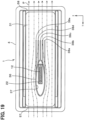
- FIG. 19 is a cross-section taken along D-D line of FIG. 14 .
- the heat generation member 42 is located immediately below the heat dissipation member 43 as shown in FIGS. 18 , 19 , and accordingly the heat generated by the heat generation member 42 is transferred to the heat dissipation member 43 through the control board 9.
- the heat transferred to the heat dissipation member 43 is transferred from the lower surface to the upper surface of the bottom wall 30 defining the first space, and thus the heat is released in the first space.
- the thermal resistance is generated at a part between the lower surface and the upper surface of the bottom wall 30.
- the cross-sectional area for the heat conduction is large and the heat conduction path is short as compared with a general structure in which heat is transferred through a bracket, the area where the thermal resistance may be generated is made small as much as possible.
- the column wall 36 is provided in the first space defined by the first space portion 31, since the column wall 36 is shaped so as not to cause turbulence in the airflow as described above, the heat released in the first space can be quickly conveyed to the outside of the first space.
- the first embodiment as described above provides the effects below.
- the vehicular antenna device 1 includes the first space portion 31 that has a cylindrical shape and is exposed to the outside air in the situation where the vehicular antenna device 1 is attached to the roof 3 of the vehicle 2, and the heat generation member 42 is arranged at a position along the lower surface that is a reverse side of the upper surface of the bottom wall 30 defining the first space.
- the heat generated by the heat generation member 42 is transferred to the heat dissipation member 43 through the control board 9, and the heat transferred to the heat dissipation member 43 is transferred from the lower surface to the upper surface of the bottom wall 30 to be released in the first space.
- the thermal resistance is generated at a part between the lower surface and the upper surface of the bottom wall 30.
- the area where the thermal resistance may be generated is made small as much as possible.
- the heat released in the first space does not stay in the first space and can be quickly conveyed by the airflow to the outside of the first space. Since the area where the thermal resistance may be generated between the heat generation member 42 and the first space portion 31 is made small as much as possible, and the heat released in the first space can be quickly conveyed to the outside of the first space, the heat of the heat generation member 42 can efficiently dissipated.
- the heat dissipation member 43 is disposed between the heat generation member 42 and the bottom wall 30. Accordingly, the heat generated by the heat generation member 42 can be appropriately transferred to the lower surface of the bottom wall 30 by the heat dissipation member 43, and the heat of the heat generation member 42 can be appropriately released.
- parts of the frame 8 other than the first space portion 31 is covered with the body cover 4. Accordingly, the sunlight is not directly irradiated to the frame 8, and the effect of the solar radiation can be suppressed. As a result, the heat dissipation from the heat generation member 42 would not be obstructed by the influence of the solar radiation.
- the second space portion 37 defining the second space in which the substrate connection portion 12 configured to electrically connect the antenna substrate 6 and the control board 9 is accommodated. Since the antenna substrate 6 and the control board 9 can be electrically connected through a part of the first space portion 31, it is unnecessary to provide wiring for electrical connection between the antenna substrate 6 and the control board 9 outside the first space portion 31. Accordingly the device can be made compact.
- each of the heat dissipation fins has a flat plate shape extending from the upper surface of the bottom wall 30 to the lower surface of the upper side wall 27.
- the upper surface of the bottom wall 30 has multiple (five in FIG. 20 , for example) heat dissipation fins 71a-71e extending rearward from the column wall 36 in the first space portion 31.
- Each heat dissipation fin 71a-71e has a flat plate shape extending from the upper surface of the bottom wall 30 to the lower surface of the upper side wall 27.
- the heat generated by the heat generation member 42 can be released in the first space from the heat dissipation fins 71a-71e.
- the frame 8 can be used as a heat sink that transfers the heat to the upper side wall 27 through the heat dissipation fins 71a-71e, and accordingly the heat of the heat generation member 42 can be dissipated appropriately.
- the length of the heat dissipation fins 38a-38e as a whole in the left-right direction is substantially the same as the width of the column wall 36 in the left-right direction.
- the heat dissipation fins are protrusions, and the length of the heat dissipation fins as a whole in the left-right direction is greater than the width of the column wall 36 in the left-right direction.
- multiple heat dissipation fins 72a, 72b, 72c, and so on protrude from the upper surface of the bottom wall 30 and are aligned in the front-rear direction and the left-right direction to form a grid pattern.
- the heat dissipation fins 72a, 72b, 72c, and so on are arranged to correspond to positions to which the heat dissipation member 43 is attached, and the length of the heat dissipation fins as a whole in the left-right direction is greater than the width of the column wall 36 in the left-right direction.
- the heat of the heat generation member 42 can be released from the heat dissipation fins 72a, 72b, 72c, and so on in the first space, and the heat of the heat generation member 42 can be released appropriately.
- the first space portion 31 and the control board 9 are in the frame 8 that is a single component.
- the first space portion and the control board are in separated frames.
- a vehicular antenna device 81 includes a frame 82 instead of the frame 8 described in the first embodiment.
- the frame 82 includes an upper frame 83a and a lower frame 83b coupled with each other.
- the upper frame 83a is a frame attached to an upper side of the roof 3 of the vehicle 2 and has the same function as the antenna attachment portion 21 described in the first embodiment.
- the upper frame 83a includes a first space portion 84 and a second space portion 85 which are similar to the first space portion 31 and the second space portion 37 respectively.
- Connection portions 86, 87 are formed on a lower side of the upper frame 83a, and a first heat dissipation member 88 is attached to the lower side of the upper frame 83a.
- An auxiliary substrate 89 is provided on the protrusion portion 13 of the antenna substrate 6.
- the lower frame 83b is a frame attached to a lower side of the roof 3 and has the same function as the control board accommodation portion 26 described in the first embodiment.
- the control board on which the heat generation member 42 is mounted is accommodated in the lower frame 83b.
- a second heat dissipation member 90 is attached on and connection terminals 91 are provided on a reverse side of the surface of the control board 9 on which the heat generation member 42 is mounted.
- a body unit 92 is assembled by engaging the antenna unit 25 to the upper frame 83.
- An attachment opening 93 is formed in the roof 3 of the vehicle 2.
- the body unit 92 is attached to the upper side of the roof 3 from above the roof 3 such that the connection portions 86, 87, the first heat dissipation member 88, and the auxiliary substrate 89 are arranged in the attachment opening 93.
- the lower frame 83b is attached to the lower side of the roof 3 from below the roof 3.
- the antenna element is electrically connected with the wireless communication circuits of the heat generation member 42 by electrically connecting the control board 9 with the auxiliary substrate 89 of the protrusion portion 13 of the antenna substrate 6 through the connection terminals 91.
- the heat generation member 42 is located immediately below the first heat dissipation member 88 and the second heat dissipation member 90, and the heat generated by the heat generation member 42 is transferred to the second heat dissipation member 90 through the control board 9.
- the heat transferred to the second heat dissipation member 90 is transferred to the first heat dissipation member 88 through the lower frame 83b.
- the heat transferred to the first heat dissipation member 88 is transferred from the lower surface to the upper surface of the bottom wall defining the first space, and thus the heat is released in the first space defined by the first space portion 84. That is, in this case also, the area where thermal resistance may occur can be made small as in the first embodiment compared to a general case where the heat is transferred through the bracket.
- a size of the attachment opening 54 in the front-rear direction and the left-right direction is necessary to be greater than at least the size of the control board 9 in the front-rear direction and the left-right direction for embedding a part of the frame 8 in the roof 3 of the vehicle 2.
- the side of the attachment opening 93 of the roof 3 of the vehicle 2 in the front-rear direction and the left-right direction is not necessary to be greater than the size of the control board 9 in the front-rear direction and the left-right direction.
- the similar effects with the first embodiment can be obtained.
- the opening area of the attachment opening 93 of the roof 3 of the vehicle 2 can be made smaller compared to the opening area of the attachment opening 54 described in the first embodiment.
- the lower frame 83b can be made larger in accordance with the size of the control board 9, and accordingly it is not needed to make the upper frame 83a larger. That is, it is possible to avoid increasing the size of the portion exposed upward from the roof 3, and to avoid impairing the appearance.
- air resistance received by the vehicular antenna device 81 can be suppressed.
- the heat generation member 42 is located below the first space portion 31, and the heat of the heat generation member 42 is transferred through the bottom wall 30.
- the heat generation member 42 may be located above the first space portion 31, and the heat of the heat generation member 42 can be transferred through the upper side wall 27.
- the heat received by the body cover 4 due to the effect of solar radiation can be suppressed from transferred to the frame 8 by providing a heat insulation material in a gap between the body cover 4 and the frame 8 or a gap between the first fixation member 5 and the second fixation member 7.
- the heat received by the roof 3 or the attachment stay 55 due to the effect of solar radiation can be suppressed from transferred to the frame 8 by providing a heat insulation material in a gap between the roof 3 and the frame 8 or a gap between the attachment stay 55 and the frame 8.
- the vehicular antenna device 1 is attached such that the front-rear direction of the first space portion 31 coincides with the longitudinal direction of the vehicle.
- the vehicular antenna device 1 may be attached such that the front-rear direction of the first space portion 31 does not coincide with the longitudinal direction of the vehicle to suppress the airflow from directly flowing into the first space.
- the second space portion 37 is located in a front part, and the heat generation member 42 and the heat dissipation member 43 are located in a rear-part.
- the positions in the front-rear direction may be swapped. That is, the heat generation member 42 and the heat dissipation member 43 may be located in the front part, and the second space portion 37 may be located in the rear part.
- the second space portion 37 is located in the first space, and the substrate connection portion 12 is accommodated in the second space to electrically connect the antenna element and the wireless communication circuit of the heat generation member 42.
- the left side wall 28 or the right side wall 29 may be recessed to form a groove, and the groove may be used as the second space portion 37. It may be preferable that the recessed portion has a shape which is not likely to cause turbulence and does not hinder the compactification of the device as a whole, similarly to the second space portion 37.
- the antenna portion is the antenna substrate 6.
- the antenna substrate 6 is held by the first fixation member 5 and the second fixation member 7.
- the antenna substrate 6 may be held in any manner.
Landscapes
- Engineering & Computer Science (AREA)
- Microelectronics & Electronic Packaging (AREA)
- Remote Sensing (AREA)
- Support Of Aerials (AREA)
- Details Of Aerials (AREA)
- Fittings On The Vehicle Exterior For Carrying Loads, And Devices For Holding Or Mounting Articles (AREA)
Description
- The present disclosure relates to a vehicular antenna device.
- There is provided a vehicular antenna device configured to be attached to a roof of a vehicle. This type of vehicular antenna device has a closed structure in which heat generating components are sealed inside a body. The heat generating component is a wireless communication module in which wireless communication circuits are integrated, for example. In the structure in which the heat generation member is sealed inside the body, the temperature of the inside of the body tends to be high due to the solar radiation in fine weather. Moreover, since the airflow is unlikely to be generated around the body during the vehicle stops, the temperature of the inside of the body is likely to become higher. When the temperature of the inside of the body becomes high, heat dissipation from the heat generation member is obstructed, and accordingly the performance may decrease due to the deterioration of the processing capability of the wireless communication circuit. Further, since the heat generation member has been multi-functionalized by adding functions such as vehicle-to-vehicle communication and the vehicle-to-infrastructure communication in recent years, the heat generation amount from the heat generation member is increasing, and accordingly the temperature of the inside of the body is further likely to become high. Under such circumstances, heat dissipation from the heat generation member is one of big problems.
JP 2017 - 152 810 A - In the configuration disclosed in
JP 2017 - 152 810 A - In the configuration disclosed in
JP 2017 - 152 810 A -
US 2012 1050 957 A1 discloses techniques which involve solar shielding an electronic device, wherein an electronic assembly includes an electronic device and a solar shield coupled to the electronic device. The solar shield has an attachment portion which attaches to the electronic device, and a shield portion coupled to the attachment portion. The shield portion prevents direct sunlight from substantially reaching a section of the electronic device. The shield portion defines (i) at least a portion of an air intake, (ii) at least a portion of an air exhaust, and (iii) at least a portion of an air passageway which extends from the air intake to the air exhaust. The air passageway overlies the section of the electronic device enabling ambient air adjacent the air intake to form natural convective airflow into the air intake and out the air exhaust through the air passageway to carry away heat from the section of the electronic device during electronic operation of the electronic device.JP 3 038 706 B2 - It is an object to provide a compact vehicular antenna device configured to appropriately release heat of a heat generation member.
- The object is solved by a vehicular antenna device according to
claim 1. Advantageous further developments are subject of the dependent claims. - According to the invention, the heat generated by the heat generation member is transferred from the second surface to the first surface, and then the heat is released in the first space. The thermal resistance may be generated at a part between the second surface and the first surface. However, since the cross-sectional area for the heat conduction is large and the heat conduction path is short as compared with a general structure in which heat is transferred through a bracket, the area where the thermal resistance may be generated is made small as much as possible. When the airflow is generated in the first space, the heat released in the first space is quickly conveyed to the outside of the first space without staying in the first space. Since the area where the thermal resistance may be generated between the heat generation member and the first space is made small as much as possible, and the heat released in the first space can be quickly conveyed to the outside of the first space, the heat of the heat generation member can be appropriately dissipated.
- The above and other objects, features and advantages of the present disclosure will become more apparent from the following detailed description taken in conjunction with the accompanying drawings. In the drawings:
-
FIG. 1 is a diagram illustrating a situation where a device is attached to a vehicle according to a first embodiment; -
FIG. 2 is a perspective view of components viewed from above; -
FIG. 3 is a perspective view of components viewed from below; -
FIG. 4 is a perspective view illustrating a first fixation member, an antenna substrate, a second fixation member, and an antenna unit; -
FIG. 5 is a perspective view of a frame viewed from above; -
FIG. 6 is a perspective view of a heat dissipation fin; -
FIG. 7 is a perspective view of the frame viewed from below; -
FIG. 8 is a perspective view illustrating the frame, a control board, a frame cover, and a frame unit; -
FIG. 9 is a perspective view illustrating the antenna unit, the frame unit, and a body unit; -
FIG. 10 is a perspective view showing a procedure for attaching the body unit to a roof of a vehicle; -
FIG. 11 is a perspective view showing a procedure for attaching a body cover to the body unit; -
FIG. 12 is a perspective view illustrating the device attached to the roof of the vehicle, the device viewed from above; -
FIG. 13 is a perspective view illustrating the device attached to the roof of the vehicle, the device viewed from below; -
FIG. 14 is a front view illustrating the device attached to the roof of the vehicle; -
FIG. 15 is a side view illustrating the device attached to the roof of the vehicle; -
FIG. 16 is a cross-section of the device attached to the roof of the vehicle; -
FIG. 17 is a cross-section of the device attached to the roof of the vehicle; -
FIG. 18 is a cross-section for explaining an airflow; -
FIG. 19 is a cross-section for explaining an airflow; -
FIG. 20 is a perspective view showing a heat dissipation fin according to a second embodiment; -
FIG. 21 is a perspective view illustrating a heat dissipation fin according to a third embodiment; -
FIG. 22 is a cross section showing a state before the attachment of the device according to a fourth embodiment; and -
FIG. 23 is a cross-section for explaining an airflow. - Hereinafter, multiple embodiments will be described with reference to the drawings. Descriptions common throughout the multiple embodiments may be omitted, and the remaining parts will be described.
- A first embodiment will be described with reference to
FIGS. 1-19 . As shown inFIG. 1 , avehicular antenna device 1 is an antenna device having a streamlined shape like a shark fin to reduce air resistance when a vehicle is travelling. Thevehicular antenna device 1 is attached to a rear part of a roof 3 (an attachment portion) such that a longitudinal direction of thevehicular antenna device 1 coincides with a longitudinal direction of avehicle 2. When theroof 3 of thevehicle 2 gradually lowers from a center part to a rear end and thevehicular antenna device 1 is attached to the lowering part, thevehicular antenna device 1 is not arranged to be along the horizontal direction but inclined such that the rear side is slightly lower than the front side. Thevehicular antenna device 1 may be installed as a standard equipment before thevehicle 2 is shipped, or may be installed after thevehicle 2 is shipped. - As shown in
FIGS. 2-3 , thevehicular antenna device 1 includes abody cover 4, afirst fixation member 5, an antenna substrate 6 (an antenna portion), asecond fixation member 7, aframe 8, acontrol board 9, and aframe cover 10 as components, and the components are fit together to assemble thevehicular antenna device 1. Hereinafter, the longitudinal direction of thevehicular antenna device 1 is referred to as a front-rear direction (Y-direction), a direction perpendicular to the longitudinal direction in a horizontal plane is referred to as a left-right direction (X-direction), and a direction perpendicular to the longitudinal direction in a vertical plane is referred to as an up-down direction (Z-direction). - As shown in
FIG. 4 , theantenna substrate 6 includes a flat plate base made of an electrically insulating material such as resin. Theantenna substrate 6 includes anelement forming portion 11 that is an upper part having a predetermined shape, and asubstrate connection portion 12 that is a lower part having a substantially rectangular shape. - An antenna element is formed on at least one side of the
element forming portion 11 by a wiring pattern. The antenna element includes an antenna element configured to transmit and receive radio waves in the frequency band for telephone communication, an antenna element configured to receive radio waves in the frequency band for GPS (Global Positioning System), an antenna element configured to transmit and receive radio waves in the frequency band for vehicle-to-vehicle communication and vehicle-to-infrastructure communication, and the like. That is, thevehicular antenna device 1 functions as an integrated antenna device configured to transmit and receive radio waves in multiple frequency bands for different uses. - A wiring pattern that electrically connects the wiring pattern on the
element forming portion 11 and a wiring patter on thecontrol board 9 described later is formed on at least one side of thesubstrate connection portion 12. The wiring pattern on theelement forming portion 11 and the wiring pattern on thesubstrate connection portion 12 are formed of copper foil, for example. Further, aprotrusion portion 13 is formed at a lower end of thesubstrate connection portion 12, and multiple connection terminals are provided on the edge of theprotrusion portion 13. - The
first fixation member 5 is made of an electrically insulating material such as resin. Thefirst fixation member 5 has a shape corresponding to an upper end of theelement forming portion 11 of theantenna substrate 6, and agroove portion 14 corresponding to the shape is formed on thefirst fixation member 5. A width of thegroove portion 14 in the left-right direction is larger than a thickness of theantenna substrate 6 such that thegroove portion 14 is configured to accommodate the upper end of theelement forming portion 11 of theantenna substrate 6. - The
second fixation member 7 is made of an electrically insulating material such as resin. An upper part of thesecond fixation member 7 is an antennasubstrate accommodation portion 15, and a lower part of thesecond fixation member 7 is aframe attachment portion 16. The antennasubstrate accommodation portion 15 extends upward from theframe attachment portion 16 and has a shape corresponding to parts of theantenna substrate 6 other than the upper end of theelement forming portion 11, and the antennasubstrate accommodation portion 15 includes agroove portion 17 corresponding to the shape of the parts of theantenna substrate 6 other than the upper end of theelement forming portion 11. A width of thegroove portion 17 in the left-right direction is larger than a thickness of theantenna substrate 6, and thegroove portion 17 is configured to accommodate the parts excepting the upper end of theelement forming portion 11. That is, the upper end of theelement forming portion 11 of theantenna substrate 6 can be accommodated in thegroove portion 14 of thefirst fixation member 5, and the remaining parts can be accommodated in thegroove portion 17 of the antennasubstrate accommodation portion 15 of thesecond fixation member 7. - The
frame attachment portion 16 is formed by bending to have a recess shape opening downward. Theframe attachment portion 16 has aflat surface portion 18 extending along the front-rear direction, andbent surface portions flat surface portion 18 and extends along the front-rear direction. A lower surface of theflat surface portion 18 faces an antenna fixation surface of an antenna attachment portion 21 (seeFIG. 5 , described later) of theframe 8 in a situation where thesecond fixation member 7 is attached to theframe 8. A through-hole portion 22 is formed in theflat surface portion 18. When the parts of theantenna substrate 6 other than the upper end of theelement forming portion 11 are accommodated in thegroove portion 17 of the antennasubstrate accommodation portion 15, thesubstrate connection portion 12 of theantenna substrate 6 is located in the through-hole portion 22 to extend through the through-hole portion 22. An engagingportion bent surface portion - The
first fixation member 5 and thesecond fixation member 7 are put together with theantenna substrate 6 to assemble anantenna unit 25. That is, theantenna substrate 6 is put together with thesecond fixation member 7 by fitting the parts of theantenna substrate 6 excepting the upper end of theelement forming portion 11 in thegroove portion 17 of the antennasubstrate accommodation portion 15 of thesecond fixation member 7. In a situation where theantenna substrate 6 is put together with thesecond fixation member 7, the upper end of theelement forming portion 11 of theantenna substrate 6 is exposed from thegroove portion 17, and thesubstrate connection portion 12 of theantenna substrate 6 extends through the through-hole portion 22 to protrude downward from the through-hole portion 22. The upper end of theelement forming portion 11 of theantenna substrate 6 is covered with thegroove portion 14 of thefirst fixation member 5, and thus thefirst fixation member 5 is put together with theantenna substrate 6 and thesecond fixation member 7. In a situation where thefirst fixation member 5 is put together with theantenna substrate 6 and thesecond fixation member 7, theantenna substrate 6 is held by thefirst fixation member 5 and thesecond fixation member 7, and thefirst fixation member 5 and the antennasubstrate accommodation portion 15 of thesecond fixation member 7 are fit together to enclose theelement forming portion 11 of theantenna substrate 6. - As shown in
FIG. 5 , theframe 8 is made of a material whose thermal conductivity is relatively high such as die-cast aluminum. An upper part of theframe 8 is theantenna attachment portion 21 described above, and a lower part is a controlboard accommodation portion 26. - The
antenna attachment portion 21 includes anupper side wall 27 extending in the front-rear direction, aleft side wall 28, aright side wall 29, and abottom wall 30. A first space is defined by afirst space portion 31 having a cylindrical shape (tunnel shape). Thefirst space portion 31 is constituted by a lower surface of theupper side wall 27, a right surface of theleft side wall 28, a left surface of theright side wall 29, and an upper surface (a surface on one side) of thebottom wall 30. That is, thefirst space portion 31 extends in the front-rear direction. Anopening portion 31a at a front end of thefirst space portion 31 and anopening portion 31b at a rear end of thefirst space portion 31 face obliquely upward. Agasket front opening portion 31a and therear opening portion 31b (seeFIGS. 2, 3 ). - An upper surface of the
upper side wall 27 is the antenna fixation surface described above. An engagedportion 34 extending in the front-rear direction is formed on a left surface of theleft side wall 28, and an engagedportion 35 extending in the front-rear direction is formed on a right surface of the right side wall 29 (seeFIG. 6 ). In the above described situation where theantenna unit 25 is attached to theframe 8, a lower surface of theflat surface portion 18 of theantenna unit 25 faces the upper surface of theupper side wall 27 of theantenna attachment portion 21, and theantenna unit 25 is fixed to theframe 8 by engaging the engagingportions bent surface portions portions right side walls - The
antenna attachment portion 21 has acolumn wall 36 connecting theupper side wall 27 and thebottom wall 30, and an inner surface of thecolumn wall 36 is asecond space portion 37 defining a second space having a cylindrical shape (tunnel shape). That is, thesecond space portion 37 extends in the up-down direction to cross thefirst space portion 31. In a situation where theantenna unit 25 is fixed to theframe 8, thesubstrate connection portion 12 of theantenna substrate 6 is accommodated in thesecond space portion 37. The transverse plane of thecolumn wall 36 has an ellipse-like shape whose diameter in the front-rear direction is longer than a diameter in the left-right direction. However, the ellipse-like shape is not a perfect ellipse shape, and a part having the largest width in the left-right direction is offset forward from the center. That is, each of the left half and the right half of thecolumn wall 36 in the transverse plane is similar to a vertical cross section of an upper half of a wing of an aircraft, and accordingly the air is likely to flow along the outline of thecolumn wall 36 and turbulence is unlikely to be generated. - As shown in
FIG. 6 , the upper surface of thebottom wall 30 has multiple (five inFIG. 6 , for example)heat dissipation fins 38a-38e extending rearward from thecolumn wall 36 in thefirst space portion 31. The length of theheat dissipation fins 38a-38e as a whole in the left-right direction is substantially the same as the width of thecolumn wall 36 in the left-right direction, and a rear end of each of theheat dissipation fins 38a-38e is located at substantially the same position as the rear end of aheat dissipation member 43 described later. A center oneheat radiation fin 38c has a flat plate shape extending from the upper surface of thebottom wall 30 to the lower surface of theupper side wall 27. - As shown in
FIG. 7 , the controlboard accommodation portion 26 has a box shape whose lower side is open. The controlboard accommodation portion 26 includes alateral wall 39 extending from a front end part of thebottom wall 30 of theantenna attachment portion 21, andlateral walls bottom wall 30 of theantenna attachment portion 21. The lower surface (a surface on the other side) of thebottom wall 30 is an upper surface of the controlboard accommodation portion 26 and works as a heat receiving surface configured to receive heat from aheat generation member 42 described later (seeFIG. 8 ). A heat dissipation member (TIM: Thermal Interface Materials) 43 including a heat dissipation sheet, a heat dissipation gel, and the like is attached to a predetermined part of the lower surface of thebottom wall 30. Theheat dissipation member 43 has substantially the same size in the front-rear direction and the left-right direction as theheat generation member 42. The controlboard accommodation portion 26 has multiplescrew hole portions 44 for fixing thecontrol board 9 to theframe 8 at multiple parts with screws, multiplescrew hole portions 45 for fixing theframe cover 10 to theframe 8 at multiple parts with screws, and multiplescrew hole portions 46 for fixing theframe 8 to theroof 3 of thevehicle 2 at multiple parts with screws. - As shown in
FIG. 8 , thecontrol board 9 includes a flat plate board made of an electrically insulating material such as resin. Thecontrol board 9 is a printed wiring board. Wiring patterns are formed and theheat generation member 42 and multiple connectors 47-49 are mounted on the lower surface of thecontrol board 9, i.e. the surface of thecontrol board 9 facing downward when thevehicular antenna device 1 is attached to theroof 3 of thevehicle 2. - The
heat generation member 42 is a wireless communication module in which wireless communication circuits are integrated, for example, and has a flat plate shape. The wireless communication circuit is a circuit including a power amplifier configured to amplify transmission signals, a low-noise amplifier configured to amplify reception signals, a bandpass filter on a transmission side, a bandpass filter on a reception side, a switcher configured to switch a supply line to the transmission side or the reception side, and the like. The connectors 47-49 are connectors to which a power supply line configured to supply power to thevehicular antenna device 1 from the outside and signal transmission line configured to transmit signals are connected. - The size of the
frame cover 10 in the front-rear direction and the left-right direction is substantially the same as that of thecontrol board 9, and theframe cover 10 is formed of, for example, a flat plate-shaped base material made of an electrically insulating material such as resin. - The
frame 8, thecontrol board 9, and theframe cover 10 are put together to assemble aframe unit 50. That is, thecontrol board 9 is accommodated in the controlboard accommodation portion 26 of theframe 8, thecontrol board 9 is fixed to theframe 8 at multiple parts withmultiple screws 51, and thus thecontrol board 9 is joined with theframe 8. That is, theheat generation member 42 is located at a part along thebottom wall 30 and immediately below theheat dissipation member 43. Since theframe cover 10 is fixed to theframe 8 at multiple parts withmultiple screws 52, theframe cover 10 and theframe 8 are fit together, and the front side, the upper side, and the lower side of thecontrol board 9 are covered. In the present embodiment, thecontrol board 9 is interposed between theheat dissipation member 43 and theheat generation member 42. However, theheat generation member 42 may be disposed on the upper surface of thecontrol board 9, i.e. the surface facing upward when thevehicular antenna device 1 is attached to theroof 3 of thevehicle 2, such that theheat generation member 42 directly contacts theheat dissipation member 43. - As shown in
FIG. 9 , the lower surface of theflat surface portion 18 of theframe attachment portion 16 of thesecond fixation member 7 faces the upper surface of theupper side wall 27 of theantenna attachment portion 21, and theantenna unit 25 is fixed to theframe 8 by engaging the engagingportions bent surface portions portions right side walls body unit 53 is assembled by engaging theantenna unit 25 to theframe unit 50. The antenna element is electrically connected with the wireless communication circuits of theheat generation member 42 by electrically connecting thecontrol board 9 with multiple connection terminals of theprotrusion portion 13 of theantenna substrate 6. - As shown in
FIG. 10 , anattachment opening 54 is formed in theroof 3 of thevehicle 2. When thebody unit 53 is attached to theroof 3, a lower part of the controlboard accommodation portion 26 of theframe 8 is fitted in the attachment opening 54 such that thebody unit 53 is supported by anattachment stay 55 of the vehicle located at a position lower than theroof 3. Theframe 8 is fixed to the attachment stay 55 of the vehicle at multiple parts withmultiple screws 56, and thus thebody unit 53 is fixed to theroof 3. - As shown in
FIG. 11 , thebody cover 4 has the openingportion 57 on the front side, the openingportion 58 on the rear side, and the openingportion 59 on the lower side. The opening portions 57-59 define a bodyunit accommodation portion 60. The openingportion 57 on the front side defines a plane that is in parallel with thefront opening portion 31a of thefirst space portion 31. The openingportion 58 on the rear side defines a plane that is in parallel with therear opening portion 31b of thefirst space portion 31. A gasket 61 (seeFIGS. 2, 3 ) is provided on a lower side of thebody cover 4. - As shown in
FIGS. 12 ,13 , when thebody unit 53 is attached to theroof 3, thebody unit 53 is covered with the bodyunit accommodation portion 60 of thebody cover 4, and thebody cover 4 is fixed to theroof 3 at multiple parts with multiple screws 62. Thus, thebody cover 4 is attached to theroof 3. Since thegasket 32 located on the front side of thefirst space portion 31 is pushed against thefront opening portion 57 of thebody cover 4, the waterproof property at theopening portion 31a of the first space is secured. Moreover, since thegasket 33 located on the rear side of thefirst space portion 31 is pushed against therear opening portion 58 of thebody cover 4, the waterproof property at theopening portion 31b of the first space is secured. Since thegasket 61 arranged on the lower side of thebody cover 4 is pushed against theroof 3, the waterproof property is secured at a part where thebody cover 4 and theroof 3 contact with each other. - The
vehicular antenna device 1 is attached to theroof 3 by attaching thebody cover 4 to theroof 3. When thevehicular antenna device 1 is attached to theroof 3, theframe 8 is covered with thebody cover 4 excepting thefirst space portion 31, and only thefirst space portion 31 is exposed to the outside air.FIG. 16 is a cross-section taken along A-A line ofFIG. 15 .FIG. 17 is a cross-section taken along B-B line ofFIG. 15 .FIG. 18 is a cross-section taken along C-C line ofFIG. 14 .FIG. 19 is a cross-section taken along D-D line ofFIG. 14 . - In the arrangement described above, the
heat generation member 42 is located immediately below theheat dissipation member 43 as shown inFIGS. 18 ,19 , and accordingly the heat generated by theheat generation member 42 is transferred to theheat dissipation member 43 through thecontrol board 9. The heat transferred to theheat dissipation member 43 is transferred from the lower surface to the upper surface of thebottom wall 30 defining the first space, and thus the heat is released in the first space. The thermal resistance is generated at a part between the lower surface and the upper surface of thebottom wall 30. However, since the cross-sectional area for the heat conduction is large and the heat conduction path is short as compared with a general structure in which heat is transferred through a bracket, the area where the thermal resistance may be generated is made small as much as possible. - When the
vehicle 2 is moving forward, for example, an airflow is generated in the first space defined by thefirst space portion 31 such that the air flows from thefront opening portion 31a to therear opening portion 31b as indicated by arrows P inFIGS. 18 ,19 . The heat released in the first space defined by thefirst space portion 31 does not stay in the first space but is conveyed by the airflow toward outside the first space. As a result, the heat of theheat generation member 42 can be appropriately dissipated. Moreover, when the outside air flows into the first space from theopening portion 31a or theopening portion 31b to generate an airflow in the first space, the same effect can be obtained even when thevehicle 2 stops. Further, when thevehicular antenna device 1 is attached such that the rear side is slightly lower than the front side, heated air in the first space moves upward to generate an airflow even when the outside air does not flow in from theopening portion 31a, or theopening portion 31b. Consequently, the same effect can be obtained. - In this case, although the
column wall 36 is provided in the first space defined by thefirst space portion 31, since thecolumn wall 36 is shaped so as not to cause turbulence in the airflow as described above, the heat released in the first space can be quickly conveyed to the outside of the first space. - The first embodiment as described above provides the effects below.
- The
vehicular antenna device 1 includes thefirst space portion 31 that has a cylindrical shape and is exposed to the outside air in the situation where thevehicular antenna device 1 is attached to theroof 3 of thevehicle 2, and theheat generation member 42 is arranged at a position along the lower surface that is a reverse side of the upper surface of thebottom wall 30 defining the first space. The heat generated by theheat generation member 42 is transferred to theheat dissipation member 43 through thecontrol board 9, and the heat transferred to theheat dissipation member 43 is transferred from the lower surface to the upper surface of thebottom wall 30 to be released in the first space. The thermal resistance is generated at a part between the lower surface and the upper surface of thebottom wall 30. However, since the cross-sectional area for the heat conduction is large and the heat conduction path is short as compared with a general structure in which heat is transferred through a bracket, the area where the thermal resistance may be generated is made small as much as possible. When an airflow is generated in the first space defined by thefirst space portion 31, the heat released in the first space does not stay in the first space and can be quickly conveyed by the airflow to the outside of the first space. Since the area where the thermal resistance may be generated between theheat generation member 42 and thefirst space portion 31 is made small as much as possible, and the heat released in the first space can be quickly conveyed to the outside of the first space, the heat of theheat generation member 42 can efficiently dissipated. - The
heat dissipation member 43 is disposed between theheat generation member 42 and thebottom wall 30. Accordingly, the heat generated by theheat generation member 42 can be appropriately transferred to the lower surface of thebottom wall 30 by theheat dissipation member 43, and the heat of theheat generation member 42 can be appropriately released. - Further, parts of the
frame 8 other than thefirst space portion 31 is covered with thebody cover 4. Accordingly, the sunlight is not directly irradiated to theframe 8, and the effect of the solar radiation can be suppressed. As a result, the heat dissipation from theheat generation member 42 would not be obstructed by the influence of the solar radiation. - Further, the
second space portion 37 defining the second space in which thesubstrate connection portion 12 configured to electrically connect theantenna substrate 6 and thecontrol board 9 is accommodated. Since theantenna substrate 6 and thecontrol board 9 can be electrically connected through a part of thefirst space portion 31, it is unnecessary to provide wiring for electrical connection between theantenna substrate 6 and thecontrol board 9 outside thefirst space portion 31. Accordingly the device can be made compact. - Next, a second embodiment will be described with reference to
FIG. 20 . In the first embodiment, only the center oneheat dissipation fin 38c of the heat dissipation fins has a flat plate shape extending from the upper surface of thebottom wall 30 to the lower surface of theupper side wall 27. However, in the second embodiment, each of the heat dissipation fins has a flat plate shape extending from the upper surface of thebottom wall 30 to the lower surface of theupper side wall 27. - As shown in
FIG. 20 , the upper surface of thebottom wall 30 has multiple (five inFIG. 20 , for example)heat dissipation fins 71a-71e extending rearward from thecolumn wall 36 in thefirst space portion 31. Eachheat dissipation fin 71a-71e has a flat plate shape extending from the upper surface of thebottom wall 30 to the lower surface of theupper side wall 27. According to the second embodiment, the heat generated by theheat generation member 42 can be released in the first space from theheat dissipation fins 71a-71e. In addition, theframe 8 can be used as a heat sink that transfers the heat to theupper side wall 27 through theheat dissipation fins 71a-71e, and accordingly the heat of theheat generation member 42 can be dissipated appropriately. - Next, a third embodiment will be described with reference to
FIG. 21 . In the first embodiment, the length of theheat dissipation fins 38a-38e as a whole in the left-right direction is substantially the same as the width of thecolumn wall 36 in the left-right direction. However, in the third embodiment, the heat dissipation fins are protrusions, and the length of the heat dissipation fins as a whole in the left-right direction is greater than the width of thecolumn wall 36 in the left-right direction. - As shown in
FIG. 21 , multipleheat dissipation fins bottom wall 30 and are aligned in the front-rear direction and the left-right direction to form a grid pattern. In this case, theheat dissipation fins heat dissipation member 43 is attached, and the length of the heat dissipation fins as a whole in the left-right direction is greater than the width of thecolumn wall 36 in the left-right direction. According to the third embodiment, the heat of theheat generation member 42 can be released from theheat dissipation fins heat generation member 42 can be released appropriately. - Next, a fourth embodiment will be described with reference to
FIGS. 22 and23 . In the first embodiment, thefirst space portion 31 and thecontrol board 9 are in theframe 8 that is a single component. However, in the fourth embodiment, the first space portion and the control board are in separated frames. - As shown in
FIGS. 22 ,23 , avehicular antenna device 81 includes aframe 82 instead of theframe 8 described in the first embodiment. Theframe 82 includes anupper frame 83a and alower frame 83b coupled with each other. - The
upper frame 83a is a frame attached to an upper side of theroof 3 of thevehicle 2 and has the same function as theantenna attachment portion 21 described in the first embodiment. Theupper frame 83a includes afirst space portion 84 and asecond space portion 85 which are similar to thefirst space portion 31 and thesecond space portion 37 respectively.Connection portions upper frame 83a, and a firstheat dissipation member 88 is attached to the lower side of theupper frame 83a. Anauxiliary substrate 89 is provided on theprotrusion portion 13 of theantenna substrate 6. Thelower frame 83b is a frame attached to a lower side of theroof 3 and has the same function as the controlboard accommodation portion 26 described in the first embodiment. The control board on which theheat generation member 42 is mounted is accommodated in thelower frame 83b. A secondheat dissipation member 90 is attached on andconnection terminals 91 are provided on a reverse side of the surface of thecontrol board 9 on which theheat generation member 42 is mounted. - A
body unit 92 is assembled by engaging theantenna unit 25 to the upper frame 83. An attachment opening 93 is formed in theroof 3 of thevehicle 2. Thebody unit 92 is attached to the upper side of theroof 3 from above theroof 3 such that theconnection portions heat dissipation member 88, and theauxiliary substrate 89 are arranged in theattachment opening 93. Thelower frame 83b is attached to the lower side of theroof 3 from below theroof 3. The antenna element is electrically connected with the wireless communication circuits of theheat generation member 42 by electrically connecting thecontrol board 9 with theauxiliary substrate 89 of theprotrusion portion 13 of theantenna substrate 6 through theconnection terminals 91. - In the arrangement described above, the
heat generation member 42 is located immediately below the firstheat dissipation member 88 and the secondheat dissipation member 90, and the heat generated by theheat generation member 42 is transferred to the secondheat dissipation member 90 through thecontrol board 9. The heat transferred to the secondheat dissipation member 90 is transferred to the firstheat dissipation member 88 through thelower frame 83b. The heat transferred to the firstheat dissipation member 88 is transferred from the lower surface to the upper surface of the bottom wall defining the first space, and thus the heat is released in the first space defined by thefirst space portion 84. That is, in this case also, the area where thermal resistance may occur can be made small as in the first embodiment compared to a general case where the heat is transferred through the bracket. - In the first embodiment in which the
control board 9 is accommodated in theframe 8, a size of the attachment opening 54 in the front-rear direction and the left-right direction is necessary to be greater than at least the size of thecontrol board 9 in the front-rear direction and the left-right direction for embedding a part of theframe 8 in theroof 3 of thevehicle 2. In contrast, since thecontrol board 9 is accommodated in thelower frame 83b in the fourth embodiment, the side of the attachment opening 93 of theroof 3 of thevehicle 2 in the front-rear direction and the left-right direction is not necessary to be greater than the size of thecontrol board 9 in the front-rear direction and the left-right direction. - According the fourth embodiment, the similar effects with the first embodiment can be obtained. Further, the opening area of the attachment opening 93 of the
roof 3 of thevehicle 2 can be made smaller compared to the opening area of the attachment opening 54 described in the first embodiment. Moreover, even when alarge control board 9 is used for higher functionality, thelower frame 83b can be made larger in accordance with the size of thecontrol board 9, and accordingly it is not needed to make theupper frame 83a larger. That is, it is possible to avoid increasing the size of the portion exposed upward from theroof 3, and to avoid impairing the appearance. In addition, air resistance received by thevehicular antenna device 81 can be suppressed. - In the above-described configuration, the
heat generation member 42 is located below thefirst space portion 31, and the heat of theheat generation member 42 is transferred through thebottom wall 30. However, theheat generation member 42 may be located above thefirst space portion 31, and the heat of theheat generation member 42 can be transferred through theupper side wall 27. - The heat received by the
body cover 4 due to the effect of solar radiation can be suppressed from transferred to theframe 8 by providing a heat insulation material in a gap between thebody cover 4 and theframe 8 or a gap between thefirst fixation member 5 and thesecond fixation member 7. The heat received by theroof 3 or the attachment stay 55 due to the effect of solar radiation can be suppressed from transferred to theframe 8 by providing a heat insulation material in a gap between theroof 3 and theframe 8 or a gap between theattachment stay 55 and theframe 8. - In the above-described configuration, the
vehicular antenna device 1 is attached such that the front-rear direction of thefirst space portion 31 coincides with the longitudinal direction of the vehicle. However, if it is concerned that thefirst space portion 31 might act as a whistle when thefirst space portion 31 receives the airflow, thevehicular antenna device 1 may be attached such that the front-rear direction of thefirst space portion 31 does not coincide with the longitudinal direction of the vehicle to suppress the airflow from directly flowing into the first space. - In the above-described configuration, the
second space portion 37 is located in a front part, and theheat generation member 42 and theheat dissipation member 43 are located in a rear-part. However, the positions in the front-rear direction may be swapped. That is, theheat generation member 42 and theheat dissipation member 43 may be located in the front part, and thesecond space portion 37 may be located in the rear part. - In the above-described configuration, the
second space portion 37 is located in the first space, and thesubstrate connection portion 12 is accommodated in the second space to electrically connect the antenna element and the wireless communication circuit of theheat generation member 42. Further, theleft side wall 28 or theright side wall 29 may be recessed to form a groove, and the groove may be used as thesecond space portion 37. It may be preferable that the recessed portion has a shape which is not likely to cause turbulence and does not hinder the compactification of the device as a whole, similarly to thesecond space portion 37. - In the above-described configuration, the antenna portion is the
antenna substrate 6. In the above-described configuration, theantenna substrate 6 is held by thefirst fixation member 5 and thesecond fixation member 7. However, theantenna substrate 6 may be held in any manner.
Claims (5)
- A vehicular antenna device (1, 81) configured to be attached to an attachment portion (3) of a vehicle (2), the vehicular antenna device comprising:- an antenna portion (6) having an antenna element; and- a frame (8, 82) accommodating a heat generation member (42), wherein- the frame includes a first space portion (31, 84) having a cylindrical shape and defining a first space, the first space portion being exposed to an outside air in a condition where the vehicular antenna device is attached to the vehicle,- the heat generation member is located along a second surface of the frame that is a reverse side of a first surface defining the first space,- the antenna portion is an antenna substrate having a flat plate shape,- the antenna element is located on an opposite side of the first space opposite from the heat generation member,- the heat generation member is mounted on a control board (9),- the frame includes a second space portion (37, 85) configured to accommodate a substrate connection portion (12) electrically connecting the antenna substrate and the control board,- the second space portion is located in the first space,- the frame (8) includes an antenna attachment portion (21) that is an upper part of the frame (8) and a control board accommodation portion (26) that is a lower part of the frame (8),- the first space portion (31, 84) is formed by an upper side wall (27), a left side wall (28), a right side wall (29), and a bottom wall (30) of the antenna attachment portion (21),- the antenna attachment portion (21) includes a column wall (36) connecting the upper side wall (27) and the bottom wall (30), and- the second space portion (37, 85) is defined by an inner surface of the column wall (36) to have a cylindrical shape.
- The vehicular antenna device according to claim 1, further comprising a heat dissipation member (43) located between the heat generation member and the second surface.
- The vehicular antenna device according to claim 1 or 2, wherein the frame is covered with a body cover (4) excepting the first space portion.
- The vehicular antenna device according to any one of claims 1 to 3, wherein the control board is accommodated in the frame (8).
- The vehicular antenna device according to any one of claims 1 to 3, wherein- the frame (82) includes an upper frame (83a) and a lower frame (83b) coupled with each other,- the first space portion is a part of the upper frame (83a), and- the control board is accommodated in the lower frame (83b).
Applications Claiming Priority (2)
| Application Number | Priority Date | Filing Date | Title |
|---|---|---|---|
| JP2018031945A JP6881349B2 (en) | 2018-02-26 | 2018-02-26 | Vehicle antenna device |
| PCT/JP2018/045893 WO2019163267A1 (en) | 2018-02-26 | 2018-12-13 | Vehicular antenna device |
Publications (3)
| Publication Number | Publication Date |
|---|---|
| EP3761446A1 EP3761446A1 (en) | 2021-01-06 |
| EP3761446A4 EP3761446A4 (en) | 2021-05-19 |
| EP3761446B1 true EP3761446B1 (en) | 2023-03-29 |
Family
ID=67687581
Family Applications (1)
| Application Number | Title | Priority Date | Filing Date |
|---|---|---|---|
| EP18907315.8A Active EP3761446B1 (en) | 2018-02-26 | 2018-12-13 | Vehicular antenna device |
Country Status (4)
| Country | Link |
|---|---|
| US (1) | US11303013B2 (en) |
| EP (1) | EP3761446B1 (en) |
| JP (1) | JP6881349B2 (en) |
| WO (1) | WO2019163267A1 (en) |
Families Citing this family (8)
| Publication number | Priority date | Publication date | Assignee | Title |
|---|---|---|---|---|
| US11008731B2 (en) * | 2017-03-31 | 2021-05-18 | Komatsu Ltd. | Work vehicle |
| KR20210048268A (en) * | 2019-10-23 | 2021-05-03 | 삼성전기주식회사 | Antenna apparatus |
| JP7298440B2 (en) * | 2019-10-24 | 2023-06-27 | 株式会社デンソー | Measuring device unit |
| CN113675604B (en) * | 2021-08-12 | 2024-01-09 | 安特微智能通讯(深圳)有限公司 | External shark fin type 5G combined antenna for automobile |
| EP4138210A1 (en) * | 2021-08-20 | 2023-02-22 | Valeo Comfort and Driving Assistance | Roof antenna module comprising a specific cooling of a control device on a vehicle roof, arrangement, motor vehicle, and method |
| FR3133274B1 (en) * | 2022-03-07 | 2024-01-19 | Continental Automotive | Vehicle antenna module |
| GB2617150A (en) * | 2022-03-31 | 2023-10-04 | Continental Automotive Tech Gmbh | An assembly suitable for facilitating heat dissipation, and an apparatus in association thereto |
| JP2023170883A (en) * | 2022-05-20 | 2023-12-01 | 株式会社豊田自動織機 | Mounting structure of on-vehicle antenna device |
Family Cites Families (36)
| Publication number | Priority date | Publication date | Assignee | Title |
|---|---|---|---|---|
| US5451970A (en) * | 1992-05-28 | 1995-09-19 | Cole; Carroll R. | Radar antenna unit having a plurality of heat dissipating fins forming on the exterior of a cone shaped chamber |
| JP2990083B2 (en) * | 1996-12-27 | 1999-12-13 | 静岡日本電気株式会社 | Mobile communication antenna device |
| JP3038706B2 (en) * | 1998-04-03 | 2000-05-08 | 日本電気株式会社 | Moving body cooling system |
| US6225956B1 (en) * | 1998-04-09 | 2001-05-01 | Schwayn D. Bradley | Illuminated vehicle antennae construction |
| JP2003179429A (en) * | 2001-12-12 | 2003-06-27 | Mitsubishi Electric Corp | Array antenna system |
| JP2003304109A (en) * | 2002-04-11 | 2003-10-24 | Kazuo Fuda | Portable telephone set |
| US20080076512A1 (en) * | 2006-09-22 | 2008-03-27 | Konami Gaming Incorporated | Gaming system comprising specific privileged area for invited players |
| JP2008085386A (en) * | 2006-09-25 | 2008-04-10 | Auto Network Gijutsu Kenkyusho:Kk | On-board antenna attaching structure |
| US20080152491A1 (en) | 2006-12-26 | 2008-06-26 | Davies Lucy V | Coatings for use in fuel system components |
| US8302550B1 (en) * | 2010-07-07 | 2012-11-06 | Woods Michael R | Antenna cover and topper device |
| US8477494B2 (en) * | 2010-08-26 | 2013-07-02 | Textron Systems Corporation | Techniques which involve solar shielding an electronic device |
| EP2495809B1 (en) * | 2011-03-03 | 2017-06-07 | Nxp B.V. | Multiband antenna |
| KR200470080Y1 (en) * | 2011-06-15 | 2013-11-26 | 위너콤 주식회사 | Patch antenna having extended ground for vehicle |
| KR101431724B1 (en) * | 2011-06-23 | 2014-08-21 | 위너콤 주식회사 | Broadcasting Antenna of Vehicle for Improving Rediation Efficiency and Preventing Interference of Signal, and Shark Fin Type Antenna Apparatus for Vehicle Therewith |
| EP2602865B1 (en) * | 2011-12-05 | 2014-10-08 | Nxp B.V. | Multi-band antenna |
| JP5920121B2 (en) * | 2012-09-03 | 2016-05-18 | 株式会社デンソー | In-vehicle antenna device |
| JP5920122B2 (en) | 2012-09-03 | 2016-05-18 | 株式会社デンソー | In-vehicle antenna device |
| JP5920123B2 (en) | 2012-09-03 | 2016-05-18 | 株式会社日本自動車部品総合研究所 | In-vehicle antenna device |
| JP6320783B2 (en) | 2014-02-10 | 2018-05-09 | 株式会社ヨコオ | Antenna device |
| US9711845B2 (en) * | 2014-07-21 | 2017-07-18 | The Boeing Company | Aerial vehicle radome assembly and methods for assembling the same |
| US20160064807A1 (en) * | 2014-08-29 | 2016-03-03 | Laird Technologies, Inc. | Multiband Vehicular Antenna Assemblies |
| US20170054204A1 (en) * | 2015-08-21 | 2017-02-23 | Laird Technologies, Inc. | V2x antenna systems |
| JP6423378B2 (en) | 2016-02-23 | 2018-11-14 | Necプラットフォームズ株式会社 | In-vehicle antenna device and heat dissipation method for in-vehicle antenna device |
| JP6393706B2 (en) * | 2016-04-28 | 2018-09-19 | 矢崎総業株式会社 | Roof module |
| US10008767B2 (en) * | 2016-04-29 | 2018-06-26 | Laird Technologies, Inc. | Vehicle-mount antenna assemblies having outer covers with back tension latching mechanisms for achieving zero-gap |
| US10141624B2 (en) * | 2016-06-08 | 2018-11-27 | Raytheon Company | Method for dynamic heat sensing in hypersonic applications |
| JP2017220609A (en) * | 2016-06-09 | 2017-12-14 | 株式会社村田製作所 | Semiconductor module |
| KR102510100B1 (en) * | 2016-06-20 | 2023-03-13 | 엘에스엠트론 주식회사 | Antenna for vehicle |
| TWM535174U (en) * | 2016-09-09 | 2017-01-11 | Ching-Yi Chen | Automobile warning device |
| JP6970496B2 (en) * | 2016-10-27 | 2021-11-24 | 株式会社ヨコオ | In-vehicle rear photography device |
| EP3605735B1 (en) * | 2017-03-31 | 2023-12-27 | Yokowo Co., Ltd | Antenna device |
| KR20180121372A (en) * | 2017-04-28 | 2018-11-07 | 엘에스엠트론 주식회사 | Antenna device for vehicle |
| EP3700012A4 (en) * | 2017-10-18 | 2022-01-12 | NTN Corporation | Cover and vehicle-mounted fin type antenna device |
| WO2019124518A1 (en) * | 2017-12-20 | 2019-06-27 | 株式会社ヨコオ | Vehicle-mounted antenna device |
| JP7356000B2 (en) * | 2019-08-14 | 2023-10-04 | ミツミ電機株式会社 | antenna device |
| JP6921917B2 (en) * | 2019-10-01 | 2021-08-18 | 原田工業株式会社 | Antenna module |
-
2018
- 2018-02-26 JP JP2018031945A patent/JP6881349B2/en active Active
- 2018-12-13 EP EP18907315.8A patent/EP3761446B1/en active Active
- 2018-12-13 WO PCT/JP2018/045893 patent/WO2019163267A1/en unknown
-
2020
- 2020-08-24 US US17/000,883 patent/US11303013B2/en active Active
Also Published As
| Publication number | Publication date |
|---|---|
| EP3761446A1 (en) | 2021-01-06 |
| US20200388910A1 (en) | 2020-12-10 |
| JP2019147421A (en) | 2019-09-05 |
| WO2019163267A1 (en) | 2019-08-29 |
| EP3761446A4 (en) | 2021-05-19 |
| JP6881349B2 (en) | 2021-06-02 |
| US11303013B2 (en) | 2022-04-12 |
Similar Documents
| Publication | Publication Date | Title |
|---|---|---|
| EP3761446B1 (en) | Vehicular antenna device | |
| US11489249B2 (en) | Vehicular communication system | |
| JP4286855B2 (en) | Radar equipment | |
| EP3188229A1 (en) | High-frequency module | |
| JP5920123B2 (en) | In-vehicle antenna device | |
| US8433257B2 (en) | Integrated waveguide transceiver | |
| US7944681B2 (en) | Electrical junction box | |
| US20060152406A1 (en) | Vehicle radar sensor assembly | |
| US10880989B2 (en) | Electrical junction box | |
| US10848649B2 (en) | Imaging device having heat radiation structure | |
| US10021812B2 (en) | Radio device with heat sink | |
| JP4023054B2 (en) | Electronic circuit unit | |
| CN113138368A (en) | Radar device and mobile platform | |
| US20180301799A1 (en) | Wireless module and image display device | |
| JP2007109993A (en) | Casing having built-in circuit board | |
| JP2020195124A (en) | Electronic apparatus | |
| US11949143B2 (en) | Communication device for vehicle | |
| JP2003017879A (en) | Heat radiating device | |
| JP4783054B2 (en) | Switching unit | |
| WO2020153344A1 (en) | Communication device for vehicle | |
| CN210405308U (en) | Communication device | |
| CN116235297A (en) | Substrate unit | |
| CN215773121U (en) | Relay data link nacelle and unmanned aerial vehicle | |
| CN218388502U (en) | Infrared core structure | |
| CN212487066U (en) | Shielding case structure with radiator and identification terminal |
Legal Events
| Date | Code | Title | Description |
|---|---|---|---|
| STAA | Information on the status of an ep patent application or granted ep patent |
Free format text: STATUS: THE INTERNATIONAL PUBLICATION HAS BEEN MADE |
|
| PUAI | Public reference made under article 153(3) epc to a published international application that has entered the european phase |
Free format text: ORIGINAL CODE: 0009012 |
|
| STAA | Information on the status of an ep patent application or granted ep patent |
Free format text: STATUS: REQUEST FOR EXAMINATION WAS MADE |
|
| 17P | Request for examination filed |
Effective date: 20200824 |
|
| AK | Designated contracting states |
Kind code of ref document: A1 Designated state(s): AL AT BE BG CH CY CZ DE DK EE ES FI FR GB GR HR HU IE IS IT LI LT LU LV MC MK MT NL NO PL PT RO RS SE SI SK SM TR |
|
| AX | Request for extension of the european patent |
Extension state: BA ME |
|
| STAA | Information on the status of an ep patent application or granted ep patent |
Free format text: STATUS: EXAMINATION IS IN PROGRESS |
|
| A4 | Supplementary search report drawn up and despatched |
Effective date: 20210420 |
|
| RIC1 | Information provided on ipc code assigned before grant |
Ipc: H01Q 1/32 20060101AFI20210414BHEP Ipc: H05K 7/20 20060101ALI20210414BHEP Ipc: H05K 1/02 20060101ALI20210414BHEP Ipc: H01Q 1/02 20060101ALI20210414BHEP |
|
| DAV | Request for validation of the european patent (deleted) | ||
| DAX | Request for extension of the european patent (deleted) | ||
| 17Q | First examination report despatched |
Effective date: 20210518 |
|
| GRAP | Despatch of communication of intention to grant a patent |
Free format text: ORIGINAL CODE: EPIDOSNIGR1 |
|
| STAA | Information on the status of an ep patent application or granted ep patent |
Free format text: STATUS: GRANT OF PATENT IS INTENDED |
|
| INTG | Intention to grant announced |
Effective date: 20221010 |
|
| GRAS | Grant fee paid |
Free format text: ORIGINAL CODE: EPIDOSNIGR3 |
|
| GRAA | (expected) grant |
Free format text: ORIGINAL CODE: 0009210 |
|
| STAA | Information on the status of an ep patent application or granted ep patent |
Free format text: STATUS: THE PATENT HAS BEEN GRANTED |
|
| AK | Designated contracting states |
Kind code of ref document: B1 Designated state(s): AL AT BE BG CH CY CZ DE DK EE ES FI FR GB GR HR HU IE IS IT LI LT LU LV MC MK MT NL NO PL PT RO RS SE SI SK SM TR |
|
| REG | Reference to a national code |
Ref country code: CH Ref legal event code: EP |
|
| REG | Reference to a national code |
Ref country code: DE Ref legal event code: R096 Ref document number: 602018047907 Country of ref document: DE |
|
| REG | Reference to a national code |
Ref country code: AT Ref legal event code: REF Ref document number: 1557316 Country of ref document: AT Kind code of ref document: T Effective date: 20230415 |
|
| REG | Reference to a national code |
Ref country code: IE Ref legal event code: FG4D |
|
| REG | Reference to a national code |
Ref country code: LT Ref legal event code: MG9D |
|
| PG25 | Lapsed in a contracting state [announced via postgrant information from national office to epo] |
Ref country code: RS Free format text: LAPSE BECAUSE OF FAILURE TO SUBMIT A TRANSLATION OF THE DESCRIPTION OR TO PAY THE FEE WITHIN THE PRESCRIBED TIME-LIMIT Effective date: 20230329 Ref country code: NO Free format text: LAPSE BECAUSE OF FAILURE TO SUBMIT A TRANSLATION OF THE DESCRIPTION OR TO PAY THE FEE WITHIN THE PRESCRIBED TIME-LIMIT Effective date: 20230629 Ref country code: LV Free format text: LAPSE BECAUSE OF FAILURE TO SUBMIT A TRANSLATION OF THE DESCRIPTION OR TO PAY THE FEE WITHIN THE PRESCRIBED TIME-LIMIT Effective date: 20230329 Ref country code: LT Free format text: LAPSE BECAUSE OF FAILURE TO SUBMIT A TRANSLATION OF THE DESCRIPTION OR TO PAY THE FEE WITHIN THE PRESCRIBED TIME-LIMIT Effective date: 20230329 Ref country code: HR Free format text: LAPSE BECAUSE OF FAILURE TO SUBMIT A TRANSLATION OF THE DESCRIPTION OR TO PAY THE FEE WITHIN THE PRESCRIBED TIME-LIMIT Effective date: 20230329 |
|
| REG | Reference to a national code |
Ref country code: NL Ref legal event code: MP Effective date: 20230329 |
|
| REG | Reference to a national code |
Ref country code: AT Ref legal event code: MK05 Ref document number: 1557316 Country of ref document: AT Kind code of ref document: T Effective date: 20230329 |
|
| PG25 | Lapsed in a contracting state [announced via postgrant information from national office to epo] |
Ref country code: SE Free format text: LAPSE BECAUSE OF FAILURE TO SUBMIT A TRANSLATION OF THE DESCRIPTION OR TO PAY THE FEE WITHIN THE PRESCRIBED TIME-LIMIT Effective date: 20230329 Ref country code: NL Free format text: LAPSE BECAUSE OF FAILURE TO SUBMIT A TRANSLATION OF THE DESCRIPTION OR TO PAY THE FEE WITHIN THE PRESCRIBED TIME-LIMIT Effective date: 20230329 Ref country code: GR Free format text: LAPSE BECAUSE OF FAILURE TO SUBMIT A TRANSLATION OF THE DESCRIPTION OR TO PAY THE FEE WITHIN THE PRESCRIBED TIME-LIMIT Effective date: 20230630 Ref country code: FI Free format text: LAPSE BECAUSE OF FAILURE TO SUBMIT A TRANSLATION OF THE DESCRIPTION OR TO PAY THE FEE WITHIN THE PRESCRIBED TIME-LIMIT Effective date: 20230329 |
|
| PG25 | Lapsed in a contracting state [announced via postgrant information from national office to epo] |
Ref country code: SM Free format text: LAPSE BECAUSE OF FAILURE TO SUBMIT A TRANSLATION OF THE DESCRIPTION OR TO PAY THE FEE WITHIN THE PRESCRIBED TIME-LIMIT Effective date: 20230329 Ref country code: RO Free format text: LAPSE BECAUSE OF FAILURE TO SUBMIT A TRANSLATION OF THE DESCRIPTION OR TO PAY THE FEE WITHIN THE PRESCRIBED TIME-LIMIT Effective date: 20230329 Ref country code: PT Free format text: LAPSE BECAUSE OF FAILURE TO SUBMIT A TRANSLATION OF THE DESCRIPTION OR TO PAY THE FEE WITHIN THE PRESCRIBED TIME-LIMIT Effective date: 20230731 Ref country code: ES Free format text: LAPSE BECAUSE OF FAILURE TO SUBMIT A TRANSLATION OF THE DESCRIPTION OR TO PAY THE FEE WITHIN THE PRESCRIBED TIME-LIMIT Effective date: 20230329 Ref country code: EE Free format text: LAPSE BECAUSE OF FAILURE TO SUBMIT A TRANSLATION OF THE DESCRIPTION OR TO PAY THE FEE WITHIN THE PRESCRIBED TIME-LIMIT Effective date: 20230329 Ref country code: AT Free format text: LAPSE BECAUSE OF FAILURE TO SUBMIT A TRANSLATION OF THE DESCRIPTION OR TO PAY THE FEE WITHIN THE PRESCRIBED TIME-LIMIT Effective date: 20230329 |
|
| PG25 | Lapsed in a contracting state [announced via postgrant information from national office to epo] |
Ref country code: SK Free format text: LAPSE BECAUSE OF FAILURE TO SUBMIT A TRANSLATION OF THE DESCRIPTION OR TO PAY THE FEE WITHIN THE PRESCRIBED TIME-LIMIT Effective date: 20230329 Ref country code: PL Free format text: LAPSE BECAUSE OF FAILURE TO SUBMIT A TRANSLATION OF THE DESCRIPTION OR TO PAY THE FEE WITHIN THE PRESCRIBED TIME-LIMIT Effective date: 20230329 Ref country code: IS Free format text: LAPSE BECAUSE OF FAILURE TO SUBMIT A TRANSLATION OF THE DESCRIPTION OR TO PAY THE FEE WITHIN THE PRESCRIBED TIME-LIMIT Effective date: 20230729 |
|
| REG | Reference to a national code |
Ref country code: DE Ref legal event code: R097 Ref document number: 602018047907 Country of ref document: DE |
|
| PG25 | Lapsed in a contracting state [announced via postgrant information from national office to epo] |
Ref country code: DK Free format text: LAPSE BECAUSE OF FAILURE TO SUBMIT A TRANSLATION OF THE DESCRIPTION OR TO PAY THE FEE WITHIN THE PRESCRIBED TIME-LIMIT Effective date: 20230329 Ref country code: CZ Free format text: LAPSE BECAUSE OF FAILURE TO SUBMIT A TRANSLATION OF THE DESCRIPTION OR TO PAY THE FEE WITHIN THE PRESCRIBED TIME-LIMIT Effective date: 20230329 |
|
| PGFP | Annual fee paid to national office [announced via postgrant information from national office to epo] |
Ref country code: DE Payment date: 20231214 Year of fee payment: 6 |
|
| PLBE | No opposition filed within time limit |
Free format text: ORIGINAL CODE: 0009261 |
|
| STAA | Information on the status of an ep patent application or granted ep patent |
Free format text: STATUS: NO OPPOSITION FILED WITHIN TIME LIMIT |
|
| 26N | No opposition filed |
Effective date: 20240103 |
|
| PG25 | Lapsed in a contracting state [announced via postgrant information from national office to epo] |
Ref country code: SI Free format text: LAPSE BECAUSE OF FAILURE TO SUBMIT A TRANSLATION OF THE DESCRIPTION OR TO PAY THE FEE WITHIN THE PRESCRIBED TIME-LIMIT Effective date: 20230329 |