EP3761391A1 - Battery pack - Google Patents
Battery pack Download PDFInfo
- Publication number
- EP3761391A1 EP3761391A1 EP19757710.9A EP19757710A EP3761391A1 EP 3761391 A1 EP3761391 A1 EP 3761391A1 EP 19757710 A EP19757710 A EP 19757710A EP 3761391 A1 EP3761391 A1 EP 3761391A1
- Authority
- EP
- European Patent Office
- Prior art keywords
- adhesive surface
- sheet
- breathable waterproof
- waterproof sheet
- gas
- Prior art date
- Legal status (The legal status is an assumption and is not a legal conclusion. Google has not performed a legal analysis and makes no representation as to the accuracy of the status listed.)
- Granted
Links
Images


Classifications
-
- H—ELECTRICITY
- H01—ELECTRIC ELEMENTS
- H01M—PROCESSES OR MEANS, e.g. BATTERIES, FOR THE DIRECT CONVERSION OF CHEMICAL ENERGY INTO ELECTRICAL ENERGY
- H01M50/00—Constructional details or processes of manufacture of the non-active parts of electrochemical cells other than fuel cells, e.g. hybrid cells
- H01M50/20—Mountings; Secondary casings or frames; Racks, modules or packs; Suspension devices; Shock absorbers; Transport or carrying devices; Holders
- H01M50/204—Racks, modules or packs for multiple batteries or multiple cells
- H01M50/207—Racks, modules or packs for multiple batteries or multiple cells characterised by their shape
- H01M50/213—Racks, modules or packs for multiple batteries or multiple cells characterised by their shape adapted for cells having curved cross-section, e.g. round or elliptic
-
- H—ELECTRICITY
- H01—ELECTRIC ELEMENTS
- H01M—PROCESSES OR MEANS, e.g. BATTERIES, FOR THE DIRECT CONVERSION OF CHEMICAL ENERGY INTO ELECTRICAL ENERGY
- H01M50/00—Constructional details or processes of manufacture of the non-active parts of electrochemical cells other than fuel cells, e.g. hybrid cells
- H01M50/20—Mountings; Secondary casings or frames; Racks, modules or packs; Suspension devices; Shock absorbers; Transport or carrying devices; Holders
- H01M50/233—Mountings; Secondary casings or frames; Racks, modules or packs; Suspension devices; Shock absorbers; Transport or carrying devices; Holders characterised by physical properties of casings or racks, e.g. dimensions
- H01M50/24—Mountings; Secondary casings or frames; Racks, modules or packs; Suspension devices; Shock absorbers; Transport or carrying devices; Holders characterised by physical properties of casings or racks, e.g. dimensions adapted for protecting batteries from their environment, e.g. from corrosion
-
- H—ELECTRICITY
- H01—ELECTRIC ELEMENTS
- H01M—PROCESSES OR MEANS, e.g. BATTERIES, FOR THE DIRECT CONVERSION OF CHEMICAL ENERGY INTO ELECTRICAL ENERGY
- H01M50/00—Constructional details or processes of manufacture of the non-active parts of electrochemical cells other than fuel cells, e.g. hybrid cells
- H01M50/30—Arrangements for facilitating escape of gases
- H01M50/317—Re-sealable arrangements
-
- H—ELECTRICITY
- H01—ELECTRIC ELEMENTS
- H01M—PROCESSES OR MEANS, e.g. BATTERIES, FOR THE DIRECT CONVERSION OF CHEMICAL ENERGY INTO ELECTRICAL ENERGY
- H01M50/00—Constructional details or processes of manufacture of the non-active parts of electrochemical cells other than fuel cells, e.g. hybrid cells
- H01M50/30—Arrangements for facilitating escape of gases
- H01M50/35—Gas exhaust passages comprising elongated, tortuous or labyrinth-shaped exhaust passages
-
- H—ELECTRICITY
- H01—ELECTRIC ELEMENTS
- H01M—PROCESSES OR MEANS, e.g. BATTERIES, FOR THE DIRECT CONVERSION OF CHEMICAL ENERGY INTO ELECTRICAL ENERGY
- H01M50/00—Constructional details or processes of manufacture of the non-active parts of electrochemical cells other than fuel cells, e.g. hybrid cells
- H01M50/30—Arrangements for facilitating escape of gases
- H01M50/375—Vent means sensitive to or responsive to temperature
-
- H—ELECTRICITY
- H01—ELECTRIC ELEMENTS
- H01M—PROCESSES OR MEANS, e.g. BATTERIES, FOR THE DIRECT CONVERSION OF CHEMICAL ENERGY INTO ELECTRICAL ENERGY
- H01M50/00—Constructional details or processes of manufacture of the non-active parts of electrochemical cells other than fuel cells, e.g. hybrid cells
- H01M50/30—Arrangements for facilitating escape of gases
- H01M50/394—Gas-pervious parts or elements
-
- Y—GENERAL TAGGING OF NEW TECHNOLOGICAL DEVELOPMENTS; GENERAL TAGGING OF CROSS-SECTIONAL TECHNOLOGIES SPANNING OVER SEVERAL SECTIONS OF THE IPC; TECHNICAL SUBJECTS COVERED BY FORMER USPC CROSS-REFERENCE ART COLLECTIONS [XRACs] AND DIGESTS
- Y02—TECHNOLOGIES OR APPLICATIONS FOR MITIGATION OR ADAPTATION AGAINST CLIMATE CHANGE
- Y02E—REDUCTION OF GREENHOUSE GAS [GHG] EMISSIONS, RELATED TO ENERGY GENERATION, TRANSMISSION OR DISTRIBUTION
- Y02E60/00—Enabling technologies; Technologies with a potential or indirect contribution to GHG emissions mitigation
- Y02E60/10—Energy storage using batteries
Definitions
- the present invention relates to a battery pack with a waterproof structure.
- a battery pack with a waterproof structure is used as a power source for an electric tool, an electrically assisted bicycle, an electric motorcycle, a hybrid electric car, an electric car, and the like, and also used for applications such as power storage at home, stores, and the like.
- the battery pack with the waterproof structure is characterized by being able to be used safely by blocking infiltration of water.
- the battery pack can achieve the waterproof structure by putting, in a packaging bag, a battery core pack in which a circuit substrate and the like are connected to a plurality of batteries and incorporating the battery core pack in an outer case (see PTL 1).
- the battery pack that houses, in the outer case, the battery core pack housed in the packaging bag includes the large packaging bag with the waterproof structure in order to store the entire battery core pack, which increases costs of parts.
- the battery core pack cannot be fixed at a fixed position in the outer case, and it takes time to dispose the battery core pack in the packaging bag at a predetermined position in the outer case, which also increases assembly costs.
- the outer case has a sealing structure.
- the outer case with the sealing structure requires a structure that prevents fluctuations in internal pressure due to temperature changes and the like.
- This structure can be achieved by opening a ventilation window in the outer case and closing the ventilation window with a breathable waterproof sheet (see PTL 2).
- the breathable waterproof sheet allows air to pass therethrough and does not allow water to pass therethrough, and thus can allow air to pass therethrough to prevent the internal pressure from fluctuating while the waterproof structure is maintained.
- the battery pack in which the ventilation window of the battery pack is closed by the breathable waterproof sheet can prevent the internal pressure from fluctuating while the waterproof structure is maintained, but has a drawback that the breathable waterproof sheet is easily damaged. This is because the breathable waterproof sheet is required to have a property of allowing air to freely pass therethrough, and thus it is difficult to form the breathable waterproof sheet with a structure that is thick and hardly damaged.
- the present invention has been made to solve such a problem, and an object of the present invention is to provide a battery pack capable of effectively preventing damage to a breathable waterproof sheet while a waterproof structure is achieved. In addition, another object of the present invention is to provide a battery pack capable of smoothly discharging high-temperature ejected gas discharged from an incorporated battery outside a case.
- a battery pack of the present invention is a battery pack including battery core pack 2 housed in outer case 1 where gas discharge hole 3 is closed with breathable waterproof sheet 4, wherein design sheet 5 covering breathable waterproof sheet 4 is fixed to outer case 2, outer case 2 further includes gas groove 7 on adhesive surface 6 where design sheet 5 is fixed, and gas groove 7 communicates with a discharge side of breathable waterproof sheet 4.
- the above battery pack is characterized by being capable of effectively preventing damage to the breathable waterproof sheet that air is allowed to permeate while the gas discharge hole is closed by the breathable waterproof sheet so that the outer case has a breathable waterproof structure, and further being capable of smoothly discharging high-temperature ejected gas ejected from a discharge valve of a battery in an abnormal state to an outside while the breathable waterproof sheet is protected.
- the design sheet is provided to cover the breathable waterproof sheet
- the gas groove is provided between the design sheet and the adhesive surface, and the gas groove is coupled to the discharge side of the breathable waterproof sheet.
- the battery pack with this structure allows air to pass through the breathable waterproof sheet and diffuses the air passing through the breathable waterproof sheet with the gas groove to discharge the air to the outside when internal pressure of the outer case changes slowly due to temperature changes or the like.
- the battery pack diffuses, with the gas groove, the gas passing through the damaged breathable waterproof sheet to an inner surface of the design sheet, the diffused discharge gas pressurizes the design sheet from the inner surface over a large area to damage or peel off the design sheet, and is quickly discharged to the outside.
- outer case 1 may include first adhesive surface 6A where breathable waterproof sheet 4 is attached, on an outer side of an outer peripheral edge of gas discharge hole 3, and further include second adhesive surface 6B where design sheet 5 is attached, on an outer side of an outer peripheral edge of first adhesive surface 6A, gas groove 7 may be provided on second adhesive surface 6B, first adhesive surface 6A may be disposed on an inner side of second adhesive surface 6B, and design sheet 5 attached to the second adhesive surface may have a larger area than an area of breathable waterproof sheet 4 attached to first adhesive surface 6A, and cover an entire surface of breathable waterproof sheet 4.
- the above battery pack is characterized in that the large design sheet covers the entire surface of the breathable waterproof sheet, and damage can be reliably prevented.
- the ejected gas ejected from an abnormal battery can be diffused to a larger area with the gas groove and discharged to the outside.
- gas grooves 7 may be provided on second adhesive surface 6B. Furthermore, in the battery pack of the present invention, gas grooves 7 may be disposed in a grid pattern.
- large recess 11 may be provided on a surface of outer case 1, a bottom of large recess 11 may serve as second adhesive surface 6B, small recess 12 may be provided on second adhesive surface 6A, a bottom surface of small recess 12 may serve as first adhesive surface 6A.
- large recess 11 may be deeper than a thickness of design sheet 5, and design sheet 5 may be attached to second adhesive surface 6B in a state where a surface of design sheet 5 does not protrude from the surface of outer case 1.
- small recess 12 may be deeper than a thickness of breathable waterproof sheet 4, air layer 9 may be provided between breathable waterproof sheet 4 and design sheet 5, and air layer 9 may communicate with gas groove 7.
- the air layer is provided between the breathable waterproof sheet and the design sheet, in the battery pack, the air that has passed through the breathable waterproof sheet is diffused in the air layer to be guided to the gas groove.
- the battery pack is characterized by being capable of rapidly damaging or peeling off the design sheet with the ejected gas to discharge the ejected gas to the outside more rapidly.
- the battery pack of the present invention is mainly mounted on an electric vehicle and supplies electric power to a driving motor.
- the present invention is used, for example, as a power source for an assisted bicycle, an electric motorcycle, an electric wheelchair, an electric tricycle, an electric cart, and the like.
- the present invention does not limit an application of the battery pack, and can also be used as a power source for various electric devices used outdoors such as an electric tool.
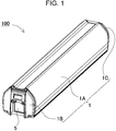
- Battery pack 100 illustrated in a perspective view of FIG. 1 and an exploded perspective view of FIG. 2 incorporates battery core pack 2 in outer case 1.
- Outer case 1 has a waterproof structure that prevents water from infiltrating from an outside, and allows air to freely flow in and out to prevent fluctuations in internal pressure.
- sub cases 1B, 1C are fixed in a watertight structure to opening portions at both ends of cylindrical main body case 1A via packings 14.
- one sub case 1B of outer case 1 is provided with gas discharge hole 3 and gas discharge hole 3 is closed by breathable waterproof sheet 4.
- Breathable waterproof sheet 4 is a sheet having innumerable fine voids through which air is allowed to pass and water is not allowed to pass.
- breathable waterproof sheet 4 discharges internal air to the outside by the pressure difference, and on the contrary, when the internal pressure becomes lower than the external pressure and a pressure difference occurs between the inside and the outside, breathable waterproof sheet 4 allows external air to flow into the inside by the pressure difference, to prevent the fluctuations of the internal pressure. Since air expands in proportion to a temperature rise, if outer case 1 has a sealing structure in order to achieve the waterproof structure, the internal pressure rises when a temperature rises, and the internal pressure falls when the temperature falls.
- gas discharge hole 3 is closed with breathable waterproof sheet 4 to prevent the fluctuations in the internal pressure due to temperature changes.
- Breathable waterproof sheet 4 is a thin sheet through which air is allowed to pass, and is easily damaged, and if damaged, a waterproof function is lost.
- a surface of breathable waterproof sheet 4 is covered with design sheet 5 in order to prevent damage to breathable waterproof sheet 4.
- Design sheet 5 is a tough sheet that has neither breathability nor water permeability and is superior in breaking strength to breathable waterproof sheet 4.
- Design sheet 5 is a plastic sheet, a metal sheet, or a laminated sheet of these.
- Design sheet 5 has a pattern or characters printed on its surface.
- design sheet 5 is a sheet having a larger area than an area of breathable waterproof sheet 4, and an outer peripheral edge of design sheet 5 is disposed on an outer side of an outer peripheral edge of breathable waterproof sheet 4 to cover and protect an entire surface of breathable waterproof sheet 4.
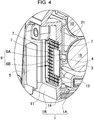
- FIGS. 4 and 5 illustrate adhesion portion between breathable waterproof sheet 4 and design sheet 5.
- Sub case 1B of outer case 1 is provided with gas discharge hole 3, and breathable waterproof sheet 4 is attached so as to close gas discharge hole 3.
- Sub case 1B, which is a part of outer case 1, is provided with first adhesive surface 6A to which breathable waterproof sheet 4 is attached, on an outer side of an outer peripheral edge of gas discharge hole 3.
- First adhesive surface 6A is, as illustrated in FIGS. 3 to 5 , a flat surface to which breathable waterproof sheet 4 is adhered and attached, which is sufficiently larger than an outer shape of gas discharge hole 3, and is disposed along the outer side of gas discharge hole 3 opening in a central portion.
- First adhesive surface 6A has a quadrangular shape, and is provided with quadrangular gas discharge hole 3 in a central portion.
- Breathable waterproof sheet 4 attached to first adhesive surface 6A closes gas discharge hole 3 opening in the central portion.
- Breathable waterproof sheet 4 is attached to first adhesive surface 6A without a gap by a method such as adhesion or welding to close gas discharge hole 3.
- Sub case 1B of outer case 1 is provided with second adhesive surface 6B along an outer side of first adhesive surface 6A.
- Second adhesive surface 6B in the figure has a quadrangular shape, and an outer shape thereof is larger than an outer shape of first adhesive surface 6A, and first adhesive surface 6A is disposed in a central portion of second adhesive surface 6B.
- Second adhesive surface 6B has a quadrangular shape, and is provided with quadrangular first adhesive surface 6A in the central portion of second adhesive surface 6B, and second adhesive surface 6B is disposed along an entire circumference of first adhesive surface 6A.
- design sheet 5 is attached to cover and protect breathable waterproof sheet 4 that adheres to first adhesive surface 6A.
- Design sheet 5 is attached to second adhesive surface 6B by a method such as adhesion or welding.
- Design sheet 5 is attached to second adhesive surface 6B and allows air to pass through design sheet 5 while protecting breathable waterproof sheet 4 from being damaged.
- Gas groove 7 is provided on second adhesive surface 6B in order to attach design sheet 5 to second adhesive surface 6B and allow air to pass through design sheet 5.
- Gas groove 7 is provided with an air passage on a back surface of design sheet 5 and allows air passing through breathable waterproof sheet 4 to pass through the air passage.
- Sub case 1B of FIGS. 3 and 4 is provided with a plurality of rows of gas grooves 7 in a grid pattern. Gas grooves 7 having this shape allow air to smoothly pass through the back surface of design sheet 5 and discharge the air to the outside. As illustrated in FIG.
- design sheet 5 is provided with passage gap 8 for allowing air to pass between the outer peripheral edge of design sheet 5 and sub case 1B in a state of being attached to second adhesive surface 6B.
- the air that has passed through gas grooves 7 is discharged to the outside from air passage gap 8 as shown by arrows in FIG. 5 .
- external air passes through passage gap 8 and gas grooves 7 and flows into the inside.
- Outer case 1 illustrated in FIGS. 3 to 5 is provided with large recess 11 on a surface side of sub case 1B, and a bottom surface of large recess 11 serves as second adhesive surface 6B, to which design sheet 5 is attached.
- Second adhesive surface 6B is provided with small recess 12 in a central portion of the bottom surface of second adhesive surface 6B, and a bottom surface of small recess 12 serves as first adhesive surface 6A, to which breathable waterproof sheet 4 is attached.
- Gas discharge hole 3 is opened in the central portion of first adhesive surface 6A, and gas discharge hole 3 is closed by breathable waterproof sheet 4 attached to first adhesive surface 6A.
- Design sheet 5 attached to second adhesive surface 6B is provided with air layer 9 between design sheet 5 and breathable waterproof sheet 4.
- Air layer 9 diffuses the air that has permeated breathable waterproof sheet 4 and guides the air to gas grooves 7.
- discharge gas damages breathable waterproof sheet 4 and diffuses in air layer 9 to pressurize an inner surface of design sheet 5 over a large area.
- the discharge gas that pressurizes the inner surface of design sheet 5 over a large area peels off or damages design sheet 5 and is instantaneously discharged to the outside.
- a structure in which sub case 1B of outer case 1 is provided with large recess 11 so that the bottom surface of large recess 11 serves as second adhesive surface 6B, and second adhesive surface 6B is provided with small recess 12 so that the bottom surface of small recess 12 serves as first adhesive surface 6A can be provided with air layer 9 between breathable waterproof sheet 4 and design sheet 5 by making a depth of large recess 11 deeper than a thickness of design sheet 5 so that design sheet 5 attached to second adhesive surface 6B does not protrude from a surface of outer case 1, and making a depth of small recess 12 deeper than a thickness of breathable waterproof sheet 4 so that breathable waterproof sheet 4 does not protrude from second adhesive surface 6B.
- the internal pressure fluctuations in outer case 1 due to the temperature changes are gentle, and causing a slight amount of air to flow in and out makes it possible to prevent the internal pressure fluctuations.
- the internal pressure of outer case 1 may rapidly rise. This is because a discharge valve (not illustrated) opens and gas is instantaneously ejected in the abnormal state of battery 10.
- Battery 10 is provided with the discharge valve (not illustrated) in order to prevent damage to a battery case due to an abnormal rise in the internal pressure.
- the discharge valve is opened and ejects the gas from the inside to prevent the battery case from bursting due to the rise in the internal pressure.
- the discharge valve In the abnormal state of battery 10, the discharge valve is opened and instantaneously ejects a large amount of high-temperature gas, and thus, in this state, the internal pressure of outer case 1 rises rapidly.
- the gas discharged from the discharge valve that is opened is instantaneously and vigorously ejected to damage breathable waterproof sheet 4.
- the discharge gas that has damaged breathable waterproof sheet 4 further damages or peels off design sheet 5 and is quickly discharged from outer case 1 to the outside.
- Breathable waterproof sheet 4 and design sheet 5 are set to have breaking strengths or attachment strengths at which breathable waterproof sheet 4 and design sheet 5 are damaged or peeled off by a gas pressure ejected in the abnormal state of battery 10.
- Battery core pack 2 incorporated in outer case 1 has a plurality of batteries 10 connected in series or in parallel.
- the plurality of batteries 10 is disposed at a fixed position in plastic battery holder 21 in parallel postures.
- circuit substrate 22 on which a protection circuit and the like for batteries 10 are mounted is fixed to battery holder 21.
- Each of batteries 10 of core pack 2 is a rechargeable lithium-ion secondary battery, but is not limited to a lithium-ion battery, and may be a non-aqueous electrolyte secondary battery other than the lithium-ion battery, a rechargeable battery such as a nickel metal hydride battery, or the like.
- Battery core pack 2 is fixed to outer case 1 and disposed in a fixed position without being housed in a waterproof bag.
- Battery core pack 2 is connected in a waterproof structure to an output terminal (not illustrated) provided to sub case 1C of outer case 1.
- a battery pack of the present invention is suitably used as a power source with a waterproof structure for an electric tool, an electrically assisted bicycle, an electric motorcycle, a hybrid electric car, an electric car, and the like.
- the battery pack is suitably used for applications such as power storage at home, stores, and the like.
Landscapes
- Chemical & Material Sciences (AREA)
- Chemical Kinetics & Catalysis (AREA)
- Electrochemistry (AREA)
- General Chemical & Material Sciences (AREA)
- Battery Mounting, Suspending (AREA)
- Gas Exhaust Devices For Batteries (AREA)
Abstract
Description
- The present invention relates to a battery pack with a waterproof structure.
- A battery pack with a waterproof structure is used as a power source for an electric tool, an electrically assisted bicycle, an electric motorcycle, a hybrid electric car, an electric car, and the like, and also used for applications such as power storage at home, stores, and the like. The battery pack with the waterproof structure is characterized by being able to be used safely by blocking infiltration of water. The battery pack can achieve the waterproof structure by putting, in a packaging bag, a battery core pack in which a circuit substrate and the like are connected to a plurality of batteries and incorporating the battery core pack in an outer case (see PTL 1).
- The battery pack that houses, in the outer case, the battery core pack housed in the packaging bag includes the large packaging bag with the waterproof structure in order to store the entire battery core pack, which increases costs of parts. In addition, there is a drawback that the battery core pack cannot be fixed at a fixed position in the outer case, and it takes time to dispose the battery core pack in the packaging bag at a predetermined position in the outer case, which also increases assembly costs.
- The above drawbacks can be solved if the outer case has a sealing structure. However, since internal air pressure fluctuates due to temperature changes, the outer case with the sealing structure requires a structure that prevents fluctuations in internal pressure due to temperature changes and the like. This structure can be achieved by opening a ventilation window in the outer case and closing the ventilation window with a breathable waterproof sheet (see PTL 2). The breathable waterproof sheet allows air to pass therethrough and does not allow water to pass therethrough, and thus can allow air to pass therethrough to prevent the internal pressure from fluctuating while the waterproof structure is maintained.
-
- PTL 1:
WO2014/184993 A - PTL 2: Unexamined Japanese Patent Publication No.
2009-158444 - The battery pack in which the ventilation window of the battery pack is closed by the breathable waterproof sheet can prevent the internal pressure from fluctuating while the waterproof structure is maintained, but has a drawback that the breathable waterproof sheet is easily damaged. This is because the breathable waterproof sheet is required to have a property of allowing air to freely pass therethrough, and thus it is difficult to form the breathable waterproof sheet with a structure that is thick and hardly damaged.
- The present invention has been made to solve such a problem, and an object of the present invention is to provide a battery pack capable of effectively preventing damage to a breathable waterproof sheet while a waterproof structure is achieved. In addition, another object of the present invention is to provide a battery pack capable of smoothly discharging high-temperature ejected gas discharged from an incorporated battery outside a case.
- A battery pack of the present invention is a battery pack including
battery core pack 2 housed inouter case 1 wheregas discharge hole 3 is closed with breathablewaterproof sheet 4, whereindesign sheet 5 covering breathablewaterproof sheet 4 is fixed toouter case 2,outer case 2 further includesgas groove 7 onadhesive surface 6 wheredesign sheet 5 is fixed, andgas groove 7 communicates with a discharge side of breathablewaterproof sheet 4. - The above battery pack is characterized by being capable of effectively preventing damage to the breathable waterproof sheet that air is allowed to permeate while the gas discharge hole is closed by the breathable waterproof sheet so that the outer case has a breathable waterproof structure, and further being capable of smoothly discharging high-temperature ejected gas ejected from a discharge valve of a battery in an abnormal state to an outside while the breathable waterproof sheet is protected. This is because, in the above battery pack, the design sheet is provided to cover the breathable waterproof sheet, the gas groove is provided between the design sheet and the adhesive surface, and the gas groove is coupled to the discharge side of the breathable waterproof sheet. The battery pack with this structure allows air to pass through the breathable waterproof sheet and diffuses the air passing through the breathable waterproof sheet with the gas groove to discharge the air to the outside when internal pressure of the outer case changes slowly due to temperature changes or the like. In addition, when the battery is in the abnormal state and the ejected gas instantaneously discharged from the discharge valve damages the breathable waterproof sheet, the battery pack diffuses, with the gas groove, the gas passing through the damaged breathable waterproof sheet to an inner surface of the design sheet, the diffused discharge gas pressurizes the design sheet from the inner surface over a large area to damage or peel off the design sheet, and is quickly discharged to the outside.
- Furthermore, in the battery pack of the present invention,
outer case 1 may include firstadhesive surface 6A where breathablewaterproof sheet 4 is attached, on an outer side of an outer peripheral edge ofgas discharge hole 3, and further include secondadhesive surface 6B wheredesign sheet 5 is attached, on an outer side of an outer peripheral edge of firstadhesive surface 6A,gas groove 7 may be provided on secondadhesive surface 6B, firstadhesive surface 6A may be disposed on an inner side of secondadhesive surface 6B, anddesign sheet 5 attached to the second adhesive surface may have a larger area than an area of breathablewaterproof sheet 4 attached to firstadhesive surface 6A, and cover an entire surface of breathablewaterproof sheet 4. - The above battery pack is characterized in that the large design sheet covers the entire surface of the breathable waterproof sheet, and damage can be reliably prevented. In addition, the ejected gas ejected from an abnormal battery can be diffused to a larger area with the gas groove and discharged to the outside.
- In addition, in the battery pack of the present invention, a plurality of rows of
gas grooves 7 may be provided on secondadhesive surface 6B. Furthermore, in the battery pack of the present invention,gas grooves 7 may be disposed in a grid pattern. - Furthermore, in the battery pack of the present invention,
large recess 11 may be provided on a surface ofouter case 1, a bottom oflarge recess 11 may serve as secondadhesive surface 6B,small recess 12 may be provided on secondadhesive surface 6A, a bottom surface ofsmall recess 12 may serve as firstadhesive surface 6A. - Furthermore, in the battery pack of the present invention,
large recess 11 may be deeper than a thickness ofdesign sheet 5, anddesign sheet 5 may be attached to secondadhesive surface 6B in a state where a surface ofdesign sheet 5 does not protrude from the surface ofouter case 1. - Furthermore, in the battery pack of the present invention,
small recess 12 may be deeper than a thickness of breathablewaterproof sheet 4,air layer 9 may be provided between breathablewaterproof sheet 4 anddesign sheet 5, andair layer 9 may communicate withgas groove 7. - Since the air layer is provided between the breathable waterproof sheet and the design sheet, in the battery pack, the air that has passed through the breathable waterproof sheet is diffused in the air layer to be guided to the gas groove. In addition, since the ejected gas that permeates the damaged breathable waterproof sheet is diffused in the air layer to be guided to the gas groove, the battery pack is characterized by being capable of rapidly damaging or peeling off the design sheet with the ejected gas to discharge the ejected gas to the outside more rapidly.
-
-
FIG. 1 is a perspective view of a battery pack according to an exemplary embodiment of the present invention. -
FIG. 2 is an exploded perspective view of the battery pack illustrated inFIG. 1 . -
FIG. 3 is an enlarged exploded perspective view of an end portion of the battery pack illustrated inFIG. 1 . -
FIG. 4 is an exploded sectional perspective view of the end portion of the battery pack illustrated inFIG. 1 . -
FIG. 5 is an enlarged sectional perspective view of the end portion of the battery pack illustrated inFIG. 1 . - An exemplary embodiment of the present invention will be described below with reference to the drawings. However, the following exemplary embodiment is merely an example of a battery pack for embodying the technical idea of the present invention, and does not limit a battery pack of the present invention.
- The battery pack of the present invention is mainly mounted on an electric vehicle and supplies electric power to a driving motor. The present invention is used, for example, as a power source for an assisted bicycle, an electric motorcycle, an electric wheelchair, an electric tricycle, an electric cart, and the like. However, the present invention does not limit an application of the battery pack, and can also be used as a power source for various electric devices used outdoors such as an electric tool.
-
Battery pack 100 illustrated in a perspective view ofFIG. 1 and an exploded perspective view ofFIG. 2 incorporatesbattery core pack 2 inouter case 1.Outer case 1 has a waterproof structure that prevents water from infiltrating from an outside, and allows air to freely flow in and out to prevent fluctuations in internal pressure. In order to achieve the waterproof structure, inouter case 1,sub cases main body case 1A viapackings 14. In order to allow air to freely flow in and out while the waterproof structure is maintained, onesub case 1B ofouter case 1 is provided withgas discharge hole 3 andgas discharge hole 3 is closed by breathablewaterproof sheet 4. - Breathable
waterproof sheet 4 is a sheet having innumerable fine voids through which air is allowed to pass and water is not allowed to pass. When the internal pressure ofouter case 1 becomes higher than external pressure and a pressure difference occurs between an inside and the outside, breathablewaterproof sheet 4 discharges internal air to the outside by the pressure difference, and on the contrary, when the internal pressure becomes lower than the external pressure and a pressure difference occurs between the inside and the outside, breathablewaterproof sheet 4 allows external air to flow into the inside by the pressure difference, to prevent the fluctuations of the internal pressure. Since air expands in proportion to a temperature rise, ifouter case 1 has a sealing structure in order to achieve the waterproof structure, the internal pressure rises when a temperature rises, and the internal pressure falls when the temperature falls. - In
outer case 1 illustrated in an enlarged exploded perspective view ofFIG. 3 ,gas discharge hole 3 is closed with breathablewaterproof sheet 4 to prevent the fluctuations in the internal pressure due to temperature changes. Breathablewaterproof sheet 4 is a thin sheet through which air is allowed to pass, and is easily damaged, and if damaged, a waterproof function is lost. Inouter case 1 ofFIG. 3 , a surface of breathablewaterproof sheet 4 is covered withdesign sheet 5 in order to prevent damage to breathablewaterproof sheet 4.Design sheet 5 is a tough sheet that has neither breathability nor water permeability and is superior in breaking strength to breathablewaterproof sheet 4.Design sheet 5 is a plastic sheet, a metal sheet, or a laminated sheet of these.Design sheet 5 has a pattern or characters printed on its surface. Furthermore,design sheet 5 is a sheet having a larger area than an area of breathablewaterproof sheet 4, and an outer peripheral edge ofdesign sheet 5 is disposed on an outer side of an outer peripheral edge of breathablewaterproof sheet 4 to cover and protect an entire surface of breathablewaterproof sheet 4. - Sectional perspective views of
FIGS. 4 and5 illustrate adhesion portion between breathablewaterproof sheet 4 anddesign sheet 5.Sub case 1B ofouter case 1 is provided withgas discharge hole 3, and breathablewaterproof sheet 4 is attached so as to closegas discharge hole 3.Sub case 1B, which is a part ofouter case 1, is provided with firstadhesive surface 6A to which breathablewaterproof sheet 4 is attached, on an outer side of an outer peripheral edge ofgas discharge hole 3. - First
adhesive surface 6A is, as illustrated inFIGS. 3 to 5 , a flat surface to which breathablewaterproof sheet 4 is adhered and attached, which is sufficiently larger than an outer shape ofgas discharge hole 3, and is disposed along the outer side ofgas discharge hole 3 opening in a central portion. Firstadhesive surface 6A has a quadrangular shape, and is provided with quadrangulargas discharge hole 3 in a central portion. Breathablewaterproof sheet 4 attached to firstadhesive surface 6A closesgas discharge hole 3 opening in the central portion. Breathablewaterproof sheet 4 is attached to firstadhesive surface 6A without a gap by a method such as adhesion or welding to closegas discharge hole 3. -
Sub case 1B ofouter case 1 is provided with secondadhesive surface 6B along an outer side of firstadhesive surface 6A. Secondadhesive surface 6B in the figure has a quadrangular shape, and an outer shape thereof is larger than an outer shape of firstadhesive surface 6A, and firstadhesive surface 6A is disposed in a central portion of secondadhesive surface 6B. Secondadhesive surface 6B has a quadrangular shape, and is provided with quadrangular firstadhesive surface 6A in the central portion of secondadhesive surface 6B, and secondadhesive surface 6B is disposed along an entire circumference of firstadhesive surface 6A. To secondadhesive surface 6B,design sheet 5 is attached to cover and protect breathablewaterproof sheet 4 that adheres to firstadhesive surface 6A.Design sheet 5 is attached to secondadhesive surface 6B by a method such as adhesion or welding. -
Design sheet 5 is attached to secondadhesive surface 6B and allows air to pass throughdesign sheet 5 while protecting breathablewaterproof sheet 4 from being damaged.Gas groove 7 is provided on secondadhesive surface 6B in order to attachdesign sheet 5 to secondadhesive surface 6B and allow air to pass throughdesign sheet 5.Gas groove 7 is provided with an air passage on a back surface ofdesign sheet 5 and allows air passing through breathablewaterproof sheet 4 to pass through the air passage.Sub case 1B ofFIGS. 3 and4 is provided with a plurality of rows ofgas grooves 7 in a grid pattern.Gas grooves 7 having this shape allow air to smoothly pass through the back surface ofdesign sheet 5 and discharge the air to the outside. As illustrated inFIG. 5 ,design sheet 5 is provided withpassage gap 8 for allowing air to pass between the outer peripheral edge ofdesign sheet 5 andsub case 1B in a state of being attached to secondadhesive surface 6B. The air that has passed throughgas grooves 7 is discharged to the outside fromair passage gap 8 as shown by arrows inFIG. 5 . In addition, external air passes throughpassage gap 8 andgas grooves 7 and flows into the inside. -
Outer case 1 illustrated inFIGS. 3 to 5 is provided withlarge recess 11 on a surface side ofsub case 1B, and a bottom surface oflarge recess 11 serves as secondadhesive surface 6B, to whichdesign sheet 5 is attached. Secondadhesive surface 6B is provided withsmall recess 12 in a central portion of the bottom surface of secondadhesive surface 6B, and a bottom surface ofsmall recess 12 serves as firstadhesive surface 6A, to which breathablewaterproof sheet 4 is attached.Gas discharge hole 3 is opened in the central portion of firstadhesive surface 6A, andgas discharge hole 3 is closed by breathablewaterproof sheet 4 attached to firstadhesive surface 6A.Design sheet 5 attached to secondadhesive surface 6B is provided withair layer 9 betweendesign sheet 5 and breathablewaterproof sheet 4.Air layer 9 diffuses the air that has permeated breathablewaterproof sheet 4 and guides the air togas grooves 7. In addition, in a state where gas is instantaneously discharged from incorporatedbattery 10, discharge gas damages breathablewaterproof sheet 4 and diffuses inair layer 9 to pressurize an inner surface ofdesign sheet 5 over a large area. The discharge gas that pressurizes the inner surface ofdesign sheet 5 over a large area peels off ordamages design sheet 5 and is instantaneously discharged to the outside. - As illustrated in
FIGS. 3 to 5 , a structure in whichsub case 1B ofouter case 1 is provided withlarge recess 11 so that the bottom surface oflarge recess 11 serves as secondadhesive surface 6B, and secondadhesive surface 6B is provided withsmall recess 12 so that the bottom surface ofsmall recess 12 serves as firstadhesive surface 6A can be provided withair layer 9 between breathablewaterproof sheet 4 anddesign sheet 5 by making a depth oflarge recess 11 deeper than a thickness ofdesign sheet 5 so thatdesign sheet 5 attached to secondadhesive surface 6B does not protrude from a surface ofouter case 1, and making a depth ofsmall recess 12 deeper than a thickness of breathablewaterproof sheet 4 so that breathablewaterproof sheet 4 does not protrude from secondadhesive surface 6B. - The internal pressure fluctuations in
outer case 1 due to the temperature changes are gentle, and causing a slight amount of air to flow in and out makes it possible to prevent the internal pressure fluctuations. However, whenbattery 10 is in an abnormal state, the internal pressure ofouter case 1 may rapidly rise. This is because a discharge valve (not illustrated) opens and gas is instantaneously ejected in the abnormal state ofbattery 10.Battery 10 is provided with the discharge valve (not illustrated) in order to prevent damage to a battery case due to an abnormal rise in the internal pressure. When the internal pressure rises to a set pressure, the discharge valve is opened and ejects the gas from the inside to prevent the battery case from bursting due to the rise in the internal pressure. In the abnormal state ofbattery 10, the discharge valve is opened and instantaneously ejects a large amount of high-temperature gas, and thus, in this state, the internal pressure ofouter case 1 rises rapidly. The gas discharged from the discharge valve that is opened is instantaneously and vigorously ejected to damage breathablewaterproof sheet 4. The discharge gas that has damaged breathablewaterproof sheet 4 further damages or peels offdesign sheet 5 and is quickly discharged fromouter case 1 to the outside. Breathablewaterproof sheet 4 anddesign sheet 5 are set to have breaking strengths or attachment strengths at which breathablewaterproof sheet 4 anddesign sheet 5 are damaged or peeled off by a gas pressure ejected in the abnormal state ofbattery 10. -
Battery core pack 2 incorporated inouter case 1 has a plurality ofbatteries 10 connected in series or in parallel. Inbattery core pack 2, the plurality ofbatteries 10 is disposed at a fixed position inplastic battery holder 21 in parallel postures. Inbattery core pack 2,circuit substrate 22 on which a protection circuit and the like forbatteries 10 are mounted is fixed tobattery holder 21. Each ofbatteries 10 ofcore pack 2 is a rechargeable lithium-ion secondary battery, but is not limited to a lithium-ion battery, and may be a non-aqueous electrolyte secondary battery other than the lithium-ion battery, a rechargeable battery such as a nickel metal hydride battery, or the like.Battery core pack 2 is fixed toouter case 1 and disposed in a fixed position without being housed in a waterproof bag.Battery core pack 2 is connected in a waterproof structure to an output terminal (not illustrated) provided to subcase 1C ofouter case 1. - A battery pack of the present invention is suitably used as a power source with a waterproof structure for an electric tool, an electrically assisted bicycle, an electric motorcycle, a hybrid electric car, an electric car, and the like. In addition, the battery pack is suitably used for applications such as power storage at home, stores, and the like.
-
- 100
- battery pack
- 1
- outer case
- 1A
- main body case
- 1B
- sub case
- 1C
- sub case
- 2
- core pack
- 3
- gas discharge hole
- 4
- breathable waterproof sheet
- 5
- design sheet
- 6
- adhesive surface
- 6A
- first adhesive surface
- 6B
- second adhesive surface
- 7
- gas groove
- 8
- passage gap
- 9
- air layer
- 10
- battery
- 11
- large recess
- 12
- small recess
- 14
- packing
- 21
- battery holder
- 22
- circuit substrate
Claims (7)
- A battery pack comprising a battery core pack housed in an outer case where a gas discharge hole is closed with a breathable waterproof sheet,
wherein a design sheet covering the breathable waterproof sheet is fixed to the outer case,
the outer case further includes a gas groove on an adhesive surface where the design sheet is fixed, and
the gas groove communicates with a discharge side of the breathable waterproof sheet. - The battery pack according to claim 1,
wherein the outer case includes a first adhesive surface where the breathable waterproof sheet is attached, on an outer side of an outer peripheral edge of the gas discharge hole, and
further includes a second adhesive surface where the design sheet is attached, on an outer side of an outer peripheral edge of the first adhesive surface,
the gas groove is provided on the second adhesive surface,
the first adhesive surface is disposed on an inner side of the second adhesive surface, and the design sheet attached to the second adhesive surface has a larger area than an area of the breathable waterproof sheet attached to the first adhesive surface, and covers an entire surface of the breathable waterproof sheet. - The battery pack according to claim 2,
wherein the gas groove includes a plurality of the gas grooves, and the plurality of the gas grooves comprise a plurality of rows of the plurality of the gas grooves provided on the second adhesive surface. - The battery pack according to claim 3,
wherein the plurality of the gas grooves are disposed in a grid pattern. - The battery pack according to any one of claims 2 to 4,
wherein a large recess is provided on a surface of the outer case,
a bottom of the large recess serves as the second adhesive surface,
a small recess is further provided on the second adhesive surface, and a bottom surface of the small recess serves as the first adhesive surface. - The battery pack according to claim 5,
wherein the large recess is deeper than a thickness of the design sheet, and
the design sheet is attached to the second adhesive surface in a state where a surface of the design sheet does not protrude from the surface of the outer case. - The battery pack according to claim 5 or 6,
wherein the small recess is deeper than a thickness of the breathable waterproof sheet,
an air layer is provided between the breathable waterproof sheet and the design sheet, and the air layer communicates with the gas groove.
Applications Claiming Priority (2)
| Application Number | Priority Date | Filing Date | Title |
|---|---|---|---|
| JP2018031717 | 2018-02-26 | ||
| PCT/JP2019/004527 WO2019163550A1 (en) | 2018-02-26 | 2019-02-08 | Battery pack |
Publications (3)
| Publication Number | Publication Date |
|---|---|
| EP3761391A1 true EP3761391A1 (en) | 2021-01-06 |
| EP3761391A4 EP3761391A4 (en) | 2021-04-21 |
| EP3761391B1 EP3761391B1 (en) | 2024-09-04 |
Family
ID=67687970
Family Applications (1)
| Application Number | Title | Priority Date | Filing Date |
|---|---|---|---|
| EP19757710.9A Active EP3761391B1 (en) | 2018-02-26 | 2019-02-08 | Battery pack |
Country Status (5)
| Country | Link |
|---|---|
| US (1) | US11431059B2 (en) |
| EP (1) | EP3761391B1 (en) |
| JP (1) | JP7301269B2 (en) |
| CN (1) | CN111771292B (en) |
| WO (1) | WO2019163550A1 (en) |
Families Citing this family (13)
| Publication number | Priority date | Publication date | Assignee | Title |
|---|---|---|---|---|
| US10141600B2 (en) | 2013-03-15 | 2018-11-27 | Apple Inc. | Thin film pattern layer battery systems |
| US10930915B2 (en) | 2014-09-02 | 2021-02-23 | Apple Inc. | Coupling tolerance accommodating contacts or leads for batteries |
| KR102807656B1 (en) * | 2020-05-13 | 2025-05-14 | 주식회사 엘지에너지솔루션 | Rechargeable battery |
| JP7543005B2 (en) * | 2020-06-22 | 2024-09-02 | パナソニックエナジー株式会社 | Battery pack |
| CN116134667A (en) * | 2020-07-31 | 2023-05-16 | 松下知识产权经营株式会社 | Battery packs and battery housings |
| US11824220B2 (en) | 2020-09-03 | 2023-11-21 | Apple Inc. | Electronic device having a vented battery barrier |
| EP4184696B1 (en) * | 2021-01-15 | 2026-05-06 | LG Energy Solution, Ltd. | Battery module and battery pack including same |
| WO2022197867A1 (en) * | 2021-03-17 | 2022-09-22 | Power.Global, Pbc | Battery module for vehicle or kiosk |
| US20220359905A1 (en) * | 2021-05-07 | 2022-11-10 | Michael A. VanderWal | Battery design for electric vehicles |
| KR20220170188A (en) * | 2021-06-22 | 2022-12-29 | 주식회사 엘지에너지솔루션 | Battery module and battery pack including the same |
| WO2023145277A1 (en) | 2022-01-27 | 2023-08-03 | パナソニックエナジ-株式会社 | Battery pack |
| WO2024048160A1 (en) | 2022-08-31 | 2024-03-07 | パナソニックエナジー株式会社 | Battery pack |
| US20250195924A1 (en) * | 2023-12-18 | 2025-06-19 | Cchangzhou Shine Science & Technology Co. Ltd. | Atmospheric pressure compensation control system for powered air-purifying respirator and method |
Family Cites Families (15)
| Publication number | Priority date | Publication date | Assignee | Title |
|---|---|---|---|---|
| JPS60133575U (en) | 1984-02-15 | 1985-09-05 | 日本電池株式会社 | Collective battery storage container |
| JPH05188457A (en) * | 1992-01-09 | 1993-07-30 | Fuji Photo Film Co Ltd | Waterproof case |
| JP2009158444A (en) | 2007-12-28 | 2009-07-16 | Kenwood Corp | Waterproof battery pack charging system |
| CN107257152B (en) | 2011-04-28 | 2021-04-09 | 佐尔循环公司 | System for updating data, operating parameters and/or software |
| CN202101079U (en) * | 2011-06-07 | 2012-01-04 | 广东诺博尔电子科技有限公司 | Traditional light source arc-shaped wall lamp |
| JP5993443B2 (en) | 2011-08-10 | 2016-09-14 | ゾール サーキュレイション インコーポレイテッド | Battery retention latch mechanism |
| JP5880109B2 (en) * | 2012-02-16 | 2016-03-08 | 日産自動車株式会社 | Battery pack explosion-proof valve |
| DE102012022346B4 (en) * | 2012-11-15 | 2018-03-22 | Mann+Hummel Gmbh | Battery Housing |
| WO2014184993A1 (en) | 2013-05-15 | 2014-11-20 | 三洋電機株式会社 | Battery pack and battery pack manufacturing method |
| CN104079106B (en) * | 2014-07-08 | 2017-02-01 | 上海博邦汽车技术有限公司 | Waterproof breathable film |
| CN118738693A (en) * | 2015-12-10 | 2024-10-01 | 宁德时代新能源科技股份有限公司 | Battery Pack |
| CN205583018U (en) * | 2016-05-04 | 2016-09-14 | 惠州市沃瑞科技有限公司 | Use quick pressure release balanced valve of battery package |
| KR101896367B1 (en) * | 2016-07-08 | 2018-10-24 | 주식회사 아모그린텍 | Breathable waterproof sheet |
| CN206098513U (en) | 2016-08-31 | 2017-04-12 | 浙江伊卡新能源汽车有限公司 | Explosion -proof valve |
| CN206349430U (en) * | 2016-11-03 | 2017-07-21 | 南京骏睿新能源汽车科技有限公司 | A kind of electric automobile power battery relief valve device |
-
2019
- 2019-02-08 WO PCT/JP2019/004527 patent/WO2019163550A1/en not_active Ceased
- 2019-02-08 EP EP19757710.9A patent/EP3761391B1/en active Active
- 2019-02-08 CN CN201980013032.6A patent/CN111771292B/en active Active
- 2019-02-08 US US16/975,467 patent/US11431059B2/en active Active
- 2019-02-08 JP JP2020501668A patent/JP7301269B2/en active Active
Also Published As
| Publication number | Publication date |
|---|---|
| CN111771292A (en) | 2020-10-13 |
| JP7301269B2 (en) | 2023-07-03 |
| JPWO2019163550A1 (en) | 2021-02-04 |
| US11431059B2 (en) | 2022-08-30 |
| WO2019163550A1 (en) | 2019-08-29 |
| EP3761391B1 (en) | 2024-09-04 |
| EP3761391A4 (en) | 2021-04-21 |
| US20210020884A1 (en) | 2021-01-21 |
| CN111771292B (en) | 2023-05-05 |
Similar Documents
| Publication | Publication Date | Title |
|---|---|---|
| US11431059B2 (en) | Battery pack | |
| TWI890834B (en) | Battery module, battery pack comprising the same, and vehicle | |
| JP3595346B2 (en) | Battery sealing plate coated with protective film and battery using the same | |
| US11962031B2 (en) | Ventilation device for battery and battery comprising the same | |
| ES2985263T3 (en) | Ventilation device and method of manufacturing it | |
| EP2262033A1 (en) | Electric storage device | |
| US12567644B2 (en) | Battery housing with a protective cap, battery and motor vehicle | |
| CN105189284A (en) | Boat with electric drive | |
| KR20160128214A (en) | Storage device | |
| EP2330655B1 (en) | Secondary battery | |
| JP4351642B2 (en) | Soft cell built-in rechargeable battery and method of manufacturing the same | |
| JP5456952B2 (en) | Battery with safety valve | |
| US20260058234A1 (en) | Battery pack | |
| JP4948038B2 (en) | Pack battery | |
| JP4064000B2 (en) | Battery pack and portable device using the battery pack | |
| JP4284172B2 (en) | Battery | |
| JP4925725B2 (en) | Pack battery | |
| CN117916970A (en) | Battery discharge port protector | |
| JP2020107552A (en) | Power storage device | |
| EP1657765B1 (en) | Safety device of battery | |
| US20080318117A1 (en) | Battery assembly including an electrolyte management system | |
| EP4224603B1 (en) | Battery pack | |
| US20060263682A1 (en) | Battery sheath having ferrite stainless steel layer and rechargeable battery using the same | |
| JP2002324526A (en) | Battery covering structure, method, and battery capable of preventing air from entering during abnormal heating | |
| KR100731425B1 (en) | Pouch Type Lithium Secondary Battery |
Legal Events
| Date | Code | Title | Description |
|---|---|---|---|
| STAA | Information on the status of an ep patent application or granted ep patent |
Free format text: STATUS: THE INTERNATIONAL PUBLICATION HAS BEEN MADE |
|
| PUAI | Public reference made under article 153(3) epc to a published international application that has entered the european phase |
Free format text: ORIGINAL CODE: 0009012 |
|
| STAA | Information on the status of an ep patent application or granted ep patent |
Free format text: STATUS: REQUEST FOR EXAMINATION WAS MADE |
|
| 17P | Request for examination filed |
Effective date: 20200917 |
|
| AK | Designated contracting states |
Kind code of ref document: A1 Designated state(s): AL AT BE BG CH CY CZ DE DK EE ES FI FR GB GR HR HU IE IS IT LI LT LU LV MC MK MT NL NO PL PT RO RS SE SI SK SM TR |
|
| AX | Request for extension of the european patent |
Extension state: BA ME |
|
| A4 | Supplementary search report drawn up and despatched |
Effective date: 20210324 |
|
| RIC1 | Information provided on ipc code assigned before grant |
Ipc: H01M 50/202 20210101AFI20210318BHEP Ipc: H01M 50/317 20210101ALI20210318BHEP Ipc: H01M 50/35 20210101ALI20210318BHEP Ipc: H01M 50/375 20210101ALI20210318BHEP Ipc: H01M 50/30 20210101ALI20210318BHEP Ipc: B32B 3/26 20060101ALI20210318BHEP |
|
| DAV | Request for validation of the european patent (deleted) | ||
| DAX | Request for extension of the european patent (deleted) | ||
| REG | Reference to a national code |
Ref country code: DE Ref legal event code: R079 Free format text: PREVIOUS MAIN CLASS: H01M0002100000 Ipc: H01M0050213000 Ref document number: 602019058317 Country of ref document: DE |
|
| GRAP | Despatch of communication of intention to grant a patent |
Free format text: ORIGINAL CODE: EPIDOSNIGR1 |
|
| RIC1 | Information provided on ipc code assigned before grant |
Ipc: B32B 3/26 20060101ALI20240216BHEP Ipc: H01M 50/30 20210101ALI20240216BHEP Ipc: H01M 50/375 20210101ALI20240216BHEP Ipc: H01M 50/35 20210101ALI20240216BHEP Ipc: H01M 50/317 20210101ALI20240216BHEP Ipc: H01M 50/24 20210101ALI20240216BHEP Ipc: H01M 50/213 20210101AFI20240216BHEP |
|
| STAA | Information on the status of an ep patent application or granted ep patent |
Free format text: STATUS: GRANT OF PATENT IS INTENDED |
|
| INTG | Intention to grant announced |
Effective date: 20240328 |
|
| GRAS | Grant fee paid |
Free format text: ORIGINAL CODE: EPIDOSNIGR3 |
|
| GRAA | (expected) grant |
Free format text: ORIGINAL CODE: 0009210 |
|
| STAA | Information on the status of an ep patent application or granted ep patent |
Free format text: STATUS: THE PATENT HAS BEEN GRANTED |
|
| RAP3 | Party data changed (applicant data changed or rights of an application transferred) |
Owner name: SANYO ELECTRIC CO., LTD. |
|
| RAP1 | Party data changed (applicant data changed or rights of an application transferred) |
Owner name: PANASONIC ENERGY CO., LTD. |
|
| AK | Designated contracting states |
Kind code of ref document: B1 Designated state(s): AL AT BE BG CH CY CZ DE DK EE ES FI FR GB GR HR HU IE IS IT LI LT LU LV MC MK MT NL NO PL PT RO RS SE SI SK SM TR |
|
| REG | Reference to a national code |
Ref country code: GB Ref legal event code: FG4D |
|
| REG | Reference to a national code |
Ref country code: CH Ref legal event code: EP |
|
| REG | Reference to a national code |
Ref country code: IE Ref legal event code: FG4D |
|
| REG | Reference to a national code |
Ref country code: DE Ref legal event code: R096 Ref document number: 602019058317 Country of ref document: DE |
|
| REG | Reference to a national code |
Ref country code: LT Ref legal event code: MG9D |
|
| REG | Reference to a national code |
Ref country code: NL Ref legal event code: MP Effective date: 20240904 |
|
| PG25 | Lapsed in a contracting state [announced via postgrant information from national office to epo] |
Ref country code: NO Free format text: LAPSE BECAUSE OF FAILURE TO SUBMIT A TRANSLATION OF THE DESCRIPTION OR TO PAY THE FEE WITHIN THE PRESCRIBED TIME-LIMIT Effective date: 20241204 |
|
| PG25 | Lapsed in a contracting state [announced via postgrant information from national office to epo] |
Ref country code: GR Free format text: LAPSE BECAUSE OF FAILURE TO SUBMIT A TRANSLATION OF THE DESCRIPTION OR TO PAY THE FEE WITHIN THE PRESCRIBED TIME-LIMIT Effective date: 20241205 Ref country code: PL Free format text: LAPSE BECAUSE OF FAILURE TO SUBMIT A TRANSLATION OF THE DESCRIPTION OR TO PAY THE FEE WITHIN THE PRESCRIBED TIME-LIMIT Effective date: 20240904 Ref country code: FI Free format text: LAPSE BECAUSE OF FAILURE TO SUBMIT A TRANSLATION OF THE DESCRIPTION OR TO PAY THE FEE WITHIN THE PRESCRIBED TIME-LIMIT Effective date: 20240904 |
|
| PG25 | Lapsed in a contracting state [announced via postgrant information from national office to epo] |
Ref country code: BG Free format text: LAPSE BECAUSE OF FAILURE TO SUBMIT A TRANSLATION OF THE DESCRIPTION OR TO PAY THE FEE WITHIN THE PRESCRIBED TIME-LIMIT Effective date: 20240904 |
|
| PG25 | Lapsed in a contracting state [announced via postgrant information from national office to epo] |
Ref country code: LV Free format text: LAPSE BECAUSE OF FAILURE TO SUBMIT A TRANSLATION OF THE DESCRIPTION OR TO PAY THE FEE WITHIN THE PRESCRIBED TIME-LIMIT Effective date: 20240904 |
|
| PG25 | Lapsed in a contracting state [announced via postgrant information from national office to epo] |
Ref country code: HR Free format text: LAPSE BECAUSE OF FAILURE TO SUBMIT A TRANSLATION OF THE DESCRIPTION OR TO PAY THE FEE WITHIN THE PRESCRIBED TIME-LIMIT Effective date: 20240904 |
|
| PG25 | Lapsed in a contracting state [announced via postgrant information from national office to epo] |
Ref country code: RS Free format text: LAPSE BECAUSE OF FAILURE TO SUBMIT A TRANSLATION OF THE DESCRIPTION OR TO PAY THE FEE WITHIN THE PRESCRIBED TIME-LIMIT Effective date: 20241204 Ref country code: ES Free format text: LAPSE BECAUSE OF FAILURE TO SUBMIT A TRANSLATION OF THE DESCRIPTION OR TO PAY THE FEE WITHIN THE PRESCRIBED TIME-LIMIT Effective date: 20240904 |
|
| PG25 | Lapsed in a contracting state [announced via postgrant information from national office to epo] |
Ref country code: RS Free format text: LAPSE BECAUSE OF FAILURE TO SUBMIT A TRANSLATION OF THE DESCRIPTION OR TO PAY THE FEE WITHIN THE PRESCRIBED TIME-LIMIT Effective date: 20241204 Ref country code: PL Free format text: LAPSE BECAUSE OF FAILURE TO SUBMIT A TRANSLATION OF THE DESCRIPTION OR TO PAY THE FEE WITHIN THE PRESCRIBED TIME-LIMIT Effective date: 20240904 Ref country code: NO Free format text: LAPSE BECAUSE OF FAILURE TO SUBMIT A TRANSLATION OF THE DESCRIPTION OR TO PAY THE FEE WITHIN THE PRESCRIBED TIME-LIMIT Effective date: 20241204 Ref country code: LV Free format text: LAPSE BECAUSE OF FAILURE TO SUBMIT A TRANSLATION OF THE DESCRIPTION OR TO PAY THE FEE WITHIN THE PRESCRIBED TIME-LIMIT Effective date: 20240904 Ref country code: HR Free format text: LAPSE BECAUSE OF FAILURE TO SUBMIT A TRANSLATION OF THE DESCRIPTION OR TO PAY THE FEE WITHIN THE PRESCRIBED TIME-LIMIT Effective date: 20240904 Ref country code: GR Free format text: LAPSE BECAUSE OF FAILURE TO SUBMIT A TRANSLATION OF THE DESCRIPTION OR TO PAY THE FEE WITHIN THE PRESCRIBED TIME-LIMIT Effective date: 20241205 Ref country code: FI Free format text: LAPSE BECAUSE OF FAILURE TO SUBMIT A TRANSLATION OF THE DESCRIPTION OR TO PAY THE FEE WITHIN THE PRESCRIBED TIME-LIMIT Effective date: 20240904 Ref country code: ES Free format text: LAPSE BECAUSE OF FAILURE TO SUBMIT A TRANSLATION OF THE DESCRIPTION OR TO PAY THE FEE WITHIN THE PRESCRIBED TIME-LIMIT Effective date: 20240904 Ref country code: BG Free format text: LAPSE BECAUSE OF FAILURE TO SUBMIT A TRANSLATION OF THE DESCRIPTION OR TO PAY THE FEE WITHIN THE PRESCRIBED TIME-LIMIT Effective date: 20240904 |
|
| REG | Reference to a national code |
Ref country code: AT Ref legal event code: MK05 Ref document number: 1721388 Country of ref document: AT Kind code of ref document: T Effective date: 20240904 |
|
| PG25 | Lapsed in a contracting state [announced via postgrant information from national office to epo] |
Ref country code: NL Free format text: LAPSE BECAUSE OF FAILURE TO SUBMIT A TRANSLATION OF THE DESCRIPTION OR TO PAY THE FEE WITHIN THE PRESCRIBED TIME-LIMIT Effective date: 20240904 |
|
| PG25 | Lapsed in a contracting state [announced via postgrant information from national office to epo] |
Ref country code: IS Free format text: LAPSE BECAUSE OF FAILURE TO SUBMIT A TRANSLATION OF THE DESCRIPTION OR TO PAY THE FEE WITHIN THE PRESCRIBED TIME-LIMIT Effective date: 20250104 Ref country code: PT Free format text: LAPSE BECAUSE OF FAILURE TO SUBMIT A TRANSLATION OF THE DESCRIPTION OR TO PAY THE FEE WITHIN THE PRESCRIBED TIME-LIMIT Effective date: 20250106 |
|
| PG25 | Lapsed in a contracting state [announced via postgrant information from national office to epo] |
Ref country code: RO Free format text: LAPSE BECAUSE OF FAILURE TO SUBMIT A TRANSLATION OF THE DESCRIPTION OR TO PAY THE FEE WITHIN THE PRESCRIBED TIME-LIMIT Effective date: 20240904 Ref country code: SM Free format text: LAPSE BECAUSE OF FAILURE TO SUBMIT A TRANSLATION OF THE DESCRIPTION OR TO PAY THE FEE WITHIN THE PRESCRIBED TIME-LIMIT Effective date: 20240904 |
|
| PG25 | Lapsed in a contracting state [announced via postgrant information from national office to epo] |
Ref country code: EE Free format text: LAPSE BECAUSE OF FAILURE TO SUBMIT A TRANSLATION OF THE DESCRIPTION OR TO PAY THE FEE WITHIN THE PRESCRIBED TIME-LIMIT Effective date: 20240904 Ref country code: AT Free format text: LAPSE BECAUSE OF FAILURE TO SUBMIT A TRANSLATION OF THE DESCRIPTION OR TO PAY THE FEE WITHIN THE PRESCRIBED TIME-LIMIT Effective date: 20240904 |
|
| PG25 | Lapsed in a contracting state [announced via postgrant information from national office to epo] |
Ref country code: CZ Free format text: LAPSE BECAUSE OF FAILURE TO SUBMIT A TRANSLATION OF THE DESCRIPTION OR TO PAY THE FEE WITHIN THE PRESCRIBED TIME-LIMIT Effective date: 20240904 |
|
| PG25 | Lapsed in a contracting state [announced via postgrant information from national office to epo] |
Ref country code: SK Free format text: LAPSE BECAUSE OF FAILURE TO SUBMIT A TRANSLATION OF THE DESCRIPTION OR TO PAY THE FEE WITHIN THE PRESCRIBED TIME-LIMIT Effective date: 20240904 Ref country code: IT Free format text: LAPSE BECAUSE OF FAILURE TO SUBMIT A TRANSLATION OF THE DESCRIPTION OR TO PAY THE FEE WITHIN THE PRESCRIBED TIME-LIMIT Effective date: 20240904 |
|
| REG | Reference to a national code |
Ref country code: DE Ref legal event code: R097 Ref document number: 602019058317 Country of ref document: DE |
|
| PG25 | Lapsed in a contracting state [announced via postgrant information from national office to epo] |
Ref country code: DK Free format text: LAPSE BECAUSE OF FAILURE TO SUBMIT A TRANSLATION OF THE DESCRIPTION OR TO PAY THE FEE WITHIN THE PRESCRIBED TIME-LIMIT Effective date: 20240904 |
|
| PLBE | No opposition filed within time limit |
Free format text: ORIGINAL CODE: 0009261 |
|
| STAA | Information on the status of an ep patent application or granted ep patent |
Free format text: STATUS: NO OPPOSITION FILED WITHIN TIME LIMIT |
|
| 26N | No opposition filed |
Effective date: 20250605 |
|
| PG25 | Lapsed in a contracting state [announced via postgrant information from national office to epo] |
Ref country code: SE Free format text: LAPSE BECAUSE OF FAILURE TO SUBMIT A TRANSLATION OF THE DESCRIPTION OR TO PAY THE FEE WITHIN THE PRESCRIBED TIME-LIMIT Effective date: 20240904 |
|
| PG25 | Lapsed in a contracting state [announced via postgrant information from national office to epo] |
Ref country code: MC Free format text: LAPSE BECAUSE OF FAILURE TO SUBMIT A TRANSLATION OF THE DESCRIPTION OR TO PAY THE FEE WITHIN THE PRESCRIBED TIME-LIMIT Effective date: 20240904 |
|
| REG | Reference to a national code |
Ref country code: CH Ref legal event code: PL |
|
| PG25 | Lapsed in a contracting state [announced via postgrant information from national office to epo] |
Ref country code: LU Free format text: LAPSE BECAUSE OF NON-PAYMENT OF DUE FEES Effective date: 20250208 |
|
| PG25 | Lapsed in a contracting state [announced via postgrant information from national office to epo] |
Ref country code: CH Free format text: LAPSE BECAUSE OF NON-PAYMENT OF DUE FEES Effective date: 20250228 |
|
| REG | Reference to a national code |
Ref country code: BE Ref legal event code: MM Effective date: 20250228 |
|
| PG25 | Lapsed in a contracting state [announced via postgrant information from national office to epo] |
Ref country code: BE Free format text: LAPSE BECAUSE OF NON-PAYMENT OF DUE FEES Effective date: 20250228 |
|
| PG25 | Lapsed in a contracting state [announced via postgrant information from national office to epo] |
Ref country code: IE Free format text: LAPSE BECAUSE OF NON-PAYMENT OF DUE FEES Effective date: 20250208 |
|
| PGFP | Annual fee paid to national office [announced via postgrant information from national office to epo] |
Ref country code: GB Payment date: 20260220 Year of fee payment: 8 |
|
| PGFP | Annual fee paid to national office [announced via postgrant information from national office to epo] |
Ref country code: DE Payment date: 20260218 Year of fee payment: 8 |
|
| PGFP | Annual fee paid to national office [announced via postgrant information from national office to epo] |
Ref country code: FR Payment date: 20260218 Year of fee payment: 8 |