EP3761145A1 - Procédé de commande d'aéronef - Google Patents
Procédé de commande d'aéronef Download PDFInfo
- Publication number
- EP3761145A1 EP3761145A1 EP20181119.7A EP20181119A EP3761145A1 EP 3761145 A1 EP3761145 A1 EP 3761145A1 EP 20181119 A EP20181119 A EP 20181119A EP 3761145 A1 EP3761145 A1 EP 3761145A1
- Authority
- EP
- European Patent Office
- Prior art keywords
- aircraft
- trajectory
- flight
- transition
- wing
- Prior art date
- Legal status (The legal status is an assumption and is not a legal conclusion. Google has not performed a legal analysis and makes no representation as to the accuracy of the status listed.)
- Granted
Links
- 238000000034 method Methods 0.000 title claims abstract description 40
- 230000007704 transition Effects 0.000 claims abstract description 49
- 238000004422 calculation algorithm Methods 0.000 claims abstract description 15
- RZVHIXYEVGDQDX-UHFFFAOYSA-N 9,10-anthraquinone Chemical compound C1=CC=C2C(=O)C3=CC=CC=C3C(=O)C2=C1 RZVHIXYEVGDQDX-UHFFFAOYSA-N 0.000 claims description 11
- 230000001133 acceleration Effects 0.000 claims description 3
- 238000005265 energy consumption Methods 0.000 claims description 2
- 230000001419 dependent effect Effects 0.000 claims 1
- 238000010586 diagram Methods 0.000 description 3
- 150000001875 compounds Chemical class 0.000 description 2
- 241000985905 Candidatus Phytoplasma solani Species 0.000 description 1
- 238000013528 artificial neural network Methods 0.000 description 1
- 238000004364 calculation method Methods 0.000 description 1
- 239000000446 fuel Substances 0.000 description 1
- 230000005484 gravity Effects 0.000 description 1
- 238000005312 nonlinear dynamic Methods 0.000 description 1
- 239000013598 vector Substances 0.000 description 1
Images


Classifications
-
- G—PHYSICS
- G05—CONTROLLING; REGULATING
- G05D—SYSTEMS FOR CONTROLLING OR REGULATING NON-ELECTRIC VARIABLES
- G05D1/00—Control of position, course, altitude or attitude of land, water, air or space vehicles, e.g. using automatic pilots
- G05D1/0005—Control of position, course, altitude or attitude of land, water, air or space vehicles, e.g. using automatic pilots with arrangements to save energy
-
- G—PHYSICS
- G05—CONTROLLING; REGULATING
- G05D—SYSTEMS FOR CONTROLLING OR REGULATING NON-ELECTRIC VARIABLES
- G05D1/00—Control of position, course, altitude or attitude of land, water, air or space vehicles, e.g. using automatic pilots
- G05D1/10—Simultaneous control of position or course in three dimensions
- G05D1/101—Simultaneous control of position or course in three dimensions specially adapted for aircraft
- G05D1/102—Simultaneous control of position or course in three dimensions specially adapted for aircraft specially adapted for vertical take-off of aircraft
-
- B—PERFORMING OPERATIONS; TRANSPORTING
- B64—AIRCRAFT; AVIATION; COSMONAUTICS
- B64C—AEROPLANES; HELICOPTERS
- B64C29/00—Aircraft capable of landing or taking-off vertically, e.g. vertical take-off and landing [VTOL] aircraft
- B64C29/0008—Aircraft capable of landing or taking-off vertically, e.g. vertical take-off and landing [VTOL] aircraft having its flight directional axis horizontal when grounded
- B64C29/0016—Aircraft capable of landing or taking-off vertically, e.g. vertical take-off and landing [VTOL] aircraft having its flight directional axis horizontal when grounded the lift during taking-off being created by free or ducted propellers or by blowers
- B64C29/0033—Aircraft capable of landing or taking-off vertically, e.g. vertical take-off and landing [VTOL] aircraft having its flight directional axis horizontal when grounded the lift during taking-off being created by free or ducted propellers or by blowers the propellers being tiltable relative to the fuselage
-
- G—PHYSICS
- G05—CONTROLLING; REGULATING
- G05D—SYSTEMS FOR CONTROLLING OR REGULATING NON-ELECTRIC VARIABLES
- G05D1/00—Control of position, course, altitude or attitude of land, water, air or space vehicles, e.g. using automatic pilots
- G05D1/10—Simultaneous control of position or course in three dimensions
- G05D1/101—Simultaneous control of position or course in three dimensions specially adapted for aircraft
- G05D1/106—Change initiated in response to external conditions, e.g. avoidance of elevated terrain or of no-fly zones
- G05D1/1062—Change initiated in response to external conditions, e.g. avoidance of elevated terrain or of no-fly zones specially adapted for avoiding bad weather conditions
-
- G—PHYSICS
- G08—SIGNALLING
- G08G—TRAFFIC CONTROL SYSTEMS
- G08G5/00—Traffic control systems for aircraft, e.g. air-traffic control [ATC]
- G08G5/003—Flight plan management
- G08G5/0034—Assembly of a flight plan
Definitions
- This disclosure relates to a method of control of an aircraft
- STOL, STOVL and VTOL aircraft are used where take-off and landing distances are restricted, for instance from ships at sea.
- Conventional VTOL aircraft include helicopters, tilt rotor aircraft and tilt wing aircraft.
- propulsors are mounted to the wings, which pivot such that the wing mounted propulsors provide either lift or forward thrust depending on the position of the wing.
- Prior tilt wing aircraft are known, such as the XC-142, Vertol VZ-2 Kaman K-16B, Hiller X-18 and the Canadair CL-84.
- Tilt-rotor aircraft are also known, for instance the Bell/Boeing V-22.
- the wing stays level relative to the fuselage, while the engines and rotors tilt to transition between hovering and forward flight.
- VTOL aircraft configurations are also known, such as vectored thrust aircraft, gyrocopters and helicopters, including compound helicopters.
- vectored thrust aircraft gyrocopters and helicopters
- helicopters including compound helicopters.
- either separate propulsors are provided for lifting and cruise flight, or engines must be tilted relative to the wings or fuselage between lifting and cruise flight. Flight during this "transition" between hovering / lifting flight and forward / cruising flight can be difficult to manage, even for skilled pilots.
- VTOL aircraft are to become more commonplace, it will be necessary to reduce the level of skill required to fly these aircraft types.
- optimisation of the flight profile may be difficult for a human pilot or for a conventional autopilot system, in view of competing demands for efficient flight within the various constraints, such as maintaining stability, altitude etc. Consequently, it is desirable to provide an automated system which automates at least part of the flight regime during transition between hovering and cruising flight in a VTOL aircraft, in order to provide for efficient, safe flight.
- a method of determining a flight trajectory of a vertical take-off aircraft having vectorable propulsion comprising:
- a method which automatically plans an aircraft flight trajectory during the transition phase which minimises the overall energy used during transition. This ensures that the aircraft is operated as efficiently as possible, using aircraft flight data, but within the aircraft flight constraints.
- the one or more aircraft flight constraints may comprise one or more of an aircraft flight corridor, an aircraft manoeuvring envelope, and a transition end schedule.
- the aircraft flight corridor may comprise maximum and / or minimum permitted altitudes for the transition trajectory, and may comprise a maximum / minimum aircraft slope.
- the aircraft manoeuvring envelope may comprise one or more of acceleration limits, roll, pitch or yaw rate limits, speed limits, propulsor power limits, propulsor power rate limits, aircraft orientation limits, wing angle of attack limits and actuator rate limits.
- the transition end schedule may comprise a maximum time and / or distance for completing the transition to forward flight.
- the method may comprise inputting live aircraft flight data to the trajectory planning algorithm to provide an updated trajectory.
- the live aircraft flight data may comprise one or more of current or projected speed, altitude, actuator feedbacks and weather data.
- the trajectory planning algorithm may comprise an aircraft flight model which relates aircraft flight control inputs to a corresponding computed trajectory.
- the aircraft flight inputs may comprise one or more of one or more propulsor thrusts, propulsor angles, wing and tail tilt angles, and aircraft flight control surface angles.
- the trajectory planning algorithm may comprise a cost function algorithm.
- the cost function algorithm may comprise a plurality of computed trajectories, and a total energy consumed by one or more propulsors for each computed trajectory.
- the method may comprise utilising the cost function algorithm to determine a computed trajectory having a minimum total propulsor energy consumption.
- the method may comprise inputting the computed trajectory to the aircraft flight model to determine the control schedule.
- the method may comprise outputting the control schedule to an autopilot system to control the aircraft to the control schedule.
- the method may comprise outputting the control schedule to a user interface to provide flight control input instructions to a pilot.
- an aircraft flight control system configured to control an aircraft having vectorable propulsion, the system comprising:
- an aircraft comprising one or more vectorable propulsors and the flight control system of the second aspect.
- the vectorable propulsors may be configured to provide vectorable thrust relative to one or more of an aircraft fuselage and an aircraft wing.
- the aircraft comprises a tilt-wing aircraft comprising one or more propulsors mounted fixedly to a wing, wherein the wing is pivotable relative to the aircraft fuselage.
- the tilt-wing aircraft may further comprise one or more cruise propulsors mounted fixed to the aircraft, and configured to provide forward thrust.
- the aircraft comprises a tilt-rotor aircraft comprising one or more propulsors pivotably mounted to a wing, wherein the wing is fixedly mounted relative to the aircraft fuselage.
- the tilt-rotor aircraft may further comprise one or more cruise propulsors mounted fixedly to the aircraft, and configured to provide forward thrust.
- a further aspect comprises a non-transitory medium comprising instructions to carry out the first aspect.
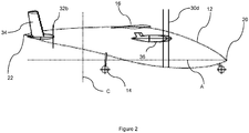
- the aircraft comprises a fuselage 12 supported by landing gear 14.
- the aircraft 10 further comprises a pair of forward main wings 16, which are located such that a centre of lift in flight of the main wings 16 is approximately adjacent a centre of gravity.
- the aircraft 10 further comprises a tail 22 (also known as an empennage), which comprises horizontal (relative to when the aircraft is in horizontal flight) tail surfaces 18 and vertical (relative to when the aircraft is in horizontal flight) tail surfaces 34 which extend from ends of each horizontal tail surface 18.
- the fuselage 12 comprises a nose 20, which defines a forward end of the aircraft 10, and the tail 22 which defines a rearward end of the aircraft 10.
- Each wing 16 mounts one or more propulsors in the form of propellers 30. Similarly, one or more further propulsors in the form of propellers 36 are mounted to the tail 22.
- a longitudinal direction A extends between the nose 20 and tail 22 in a generally horizontal direction when the aircraft 10 is in level flight or parked on the ground.
- a lateral direction (not shown) extends between tips of the main wings 16 in a direction normal to the longitudinal axis A in a generally horizontal direction.
- a vertical direction C extends in a direction generally normal to the ground when the aircraft is in level flight or parked on the ground.
- Both the main wings 16 and the horizontal tail surfaces 18 are pivotable together between a horizontal flight configuration (as shown in figure 1 ) and a vertical flight configuration (as shown in figure 4 ).
- the main propellers have a fixed angle relative to the main wing 16, with the main wing 16 being pivotable.
- the wings 16 and horizontal tail surfaces 18 present respective leading edges 26, 28 toward the forward, longitudinal direction A.
- the main wing 16 and horizontal tail surface 18 are configured to pivot about the lateral direction to transition to the hovering flight configuration, in which the leading edges 26, 28 are directed upwards, in the vertical direction, as shown in figure 1 .
- the aircraft normally starts on the ground with the wings 16 and tail 22 in the hovering configuration, as shown in figure 2 .
- the aircraft takes off in a vertical direction (though possibly with some horizontal component also), before transitioning to the horizontal flight mode as shown in figure 1 .
- the wings 16 and tail 22 pivot slowly from the hovering to the horizontal positions as speed increases.
- the aircraft transitions once more from the horizontal to the hovering modes.
- the transition phase for takeoff can be defined as the period between the aircraft wheels leaving the ground, and the aircraft having sufficient forward airspeed to maintain level flight without a vertical thrust component from the propellers 30, 32.
- the transition phase for landing can be defined as the period between the aircraft speed falling below the speed at which level flight can be maintained, and the wheels contacting the ground.
- Figure 3 shows a second aircraft 110, which is similar to the first aircraft 10, main wings 116 and a tail 122.
- Main propellers 130 are mounted to the main wings 116
- tail propellers 132 are mounted to the tail 122.
- the aircraft 110 differs from the aircraft 10, in that the aircraft 110 has fixed wings 116, which do not pivot between hovering and cruise flight. Instead, as can be seen from a comparison of the hovering flight configuration in figure 3 and the cruising flight configuration in figure 4 , the main wing and tail propellers 130, 132 pivot relative to the rest of the aircraft between the hovering and cruising configuration, while the tail 22 and main wing 16 stay level.
- Such a configuration is known as a "tilt rotor" aircraft.
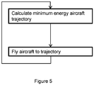
- Figure 5 shows an overview of a control scheme for controlling the aircraft 10 during the transition phase, either during takeoff or landing.
- the system is configured to first calculate a minimum energy aircraft trajectory using a reference trajectory controller.
- An autopilot then translates this reference trajectory into control inputs, to fly the aircraft 10.
- the trajectory is updated based on the actual trajectory flown, to recalculate a new minimum aircraft trajectory.
- FIG. 6 illustrates the system architecture in more detail.
- the system includes a reference trajectory controller 40.
- the reference trajectory controller determines an optimum aircraft trajectory during the transition phase (either for take-off or landing), which minimises the total propulsor energy used for the transition.
- the aircraft trajectory controller 40 calculates an aircraft trajectory, as shown in figure 7 .
- the trajectory typically comprises a path which the aircraft takes through space in the vertical plane, and may also comprise a path in the horizontal plane.
- the aircraft trajectory controller 40 outputs one or more aircraft dynamic commands, which are continually updated as the aircraft progresses through the transition phase.
- the dynamic commands include at least a height command and a forward velocity command. Consequently, the trajectory controller translates the aircraft trajectory to a series of height and forward velocity commands, which are broken down into individual time steps.
- the dynamic commands may also comprise a series of yaw, rolls and pitch commands for each time step.
- the flight controller comprises an aircraft flight model, which includes a model of how the aircraft will react to a given flight actuator input, and also includes aircraft actuator constraints, such as maximum and minimum flight actuator positions and authority, and maximum propulsor power settings and ramp rates, as well as aircraft dynamic constraints, such as flight surface angles of attack, acceleration, load and stability envelopes.
- the aircraft flight model typically also includes aircraft configuration variables, such as aircraft weight, as well as atmospheric variables, such as air temperature and pressure altitude.
- the flight controller determines how most efficiently to achieve the dynamic commands within the aircraft actuator and dynamic constraints. Once this is calculated, the flight controller outputs one or more actuator demands, such as main and tail propulsor 30, 32 demands, elevator, rudder and aileron position demands, flaps demands, and wing and tail tilt demands.
- actuator controllers 44 which use feedback loops to ensure that the actuators are in the commanded states at the correct times.
- an engine controller (not shown) is provided, which translates the required thrust demand to individual motor / engine control parameters to satisfy the thrust demand input from the flight controller 42.
- aircraft data sensors 46 continually sense aircraft dynamic parameters during flight.
- These data sensors may include air data sensors (such a pitot tubes), which provide air data such as air speeds, altitude etc.
- Further aircraft data sensors such as aircraft position sensors and attitude sensors (for instance, GPS controllers, gyroscopic sensors etc) give a full picture of the aircraft ground speed, altitude, position etc. Data from these sensors is then fed back to the flight controller 42, which updates the flight control demands to take into account deviations from the dynamic commands input to the actuators.
- the flight controller 42, actuator controllers 44 and aircraft data sensors 46 are continually updated, until the trajectory input from the reference trajectory controller is complete, and the transition period ends.
- the reference trajectory controller determines whether the aircraft significantly deviates from the optimum trajectory as determined by the reference trajectory controller. If the aircraft significantly deviates from the optimum trajectory as determined by the reference trajectory controller, data from the aircraft data sensors 46 is provided to the reference trajectory controller, which calculates an updated optimum trajectory based on the data. The process repeats as necessary, until the transition period ends, whereupon control is handed back to either a conventional autopilot, or to a human operator.
- FIG. 8 shows in more detail the process by which the reference trajectory is calculated by the reference trajectory controller 40.
- the reference trajectory controller 40 aims to provide an aircraft trajectory which minimise energy usage (i.e. fuel burn, electrical energy etc. by the propulsors) during the transition period, within certain constraints.
- the trajectory can be represented mathematically in Cartesian coordinates in the vertical plane as a series of positions from a notional origin in the horizontal (x-axis) and vertical (z-axis): x k
- k ) respectively denote future demands for the vehicle horizontal x and vertical position z at time instant k at i samples ahead, each sample being T seconds into the future.
- k denotes, at real time kTs, demand on the vehicle position at time (k+i)Ts.
- the positions x, z can take any value at any given time instant k.
- N represents the total number of time instants, which will be related to the maximum transition time, and the time resolution of the process.
- air traffic constraints may define a "flight corridor" for the aircraft, i.e. maximum and minimum heights c z and distances c x that the aircraft must fly within for a given position on the ground:
- a "flight corridor" for the aircraft i.e. maximum and minimum heights c z and distances c x that the aircraft must fly within for a given position on the ground:
- the reference trajectory controller 40 seeks to provide a trajectory which minimises the energy expenditure of the propulsion system over the time horizon of the transition period.
- the above constraints may not be present, such as where the aircraft has sufficient performance for these constraints not to impact the calculated flight trajectory, or where the aircraft is operating in uncontrolled airspace.
- Figure 7 illustrates an example trajectory (shown as a solid line), with the fight corridor defined by maximum and minimum height lines (shown as dotted lines). As can be seen, a variety of potential flight trajectories are possible within the flight corridor.
- Figure 8 illustrates the process of selecting a minimum energy aircraft trajectory in simplified terms.
- an aircraft flight model is generated, which is a state model representing the response of the aircraft over time to inputs, such as control inputs and power inputs.
- constraints e.g. airspace and aircraft constraints such as a bounded airspace, maximum and minimum flight speeds etc.
- Aircraft data such as takeoff weights may also be added.
- an initial seeded trajectory is entered to the flight model.
- the flight model is then used to determine propulsor variables necessary to enable the aircraft to follow a given trajectory, in order to calculate an energy cost for the flight trajectory.
- These propulsor variables are used as the subject of a cost function.
- the cost function explores the variables of the flight model, to find a set of variables which outputs a trajectory having a minimised energy associated with that trajectory. Details of this system are outlined below.
- X is some future state
- X is a current state
- ⁇ is a control input
- a state X can be a position in a coordinate system (such as Cartesian coordinates x, y, z), a velocity v (which may be a ground or airspeed, such as indicated airspeed), an attitude (expressed, say, as an angle), and an angular velocity.
- Control inputs may comprise aircraft main and tail propulsor 30, 32 thrust, propulsor / wing tilt angle, and flight control surface angles.
- a transition function f ( X, ⁇ ) in the form of an aircraft flight model is defined.
- the transition function includes ones or more equations of motion, which describe how the aircraft behaves in response to control inputs over time, and outputs corresponding future state vectors X.
- Typical aircraft control models are well known to the skilled person, and are for example, described in detail in Aircraft Dynamics and Automatic Control by McRuer & Graham, Flight Dynamics by Stengel.
- Other aircraft control models include Dynamic Inversion, described inter alia in " Non-Linear Dynamic Inversion of a Flexible Aircraft” by Ryan James Caverly et al, published in IFAC-PapersOnLine, Vol. 49, Issue 17, 2016, page 338 to 342 .
- the objective of the transition controller is to provide a feasible trajectory in terms of Airspeed (V), Flight Path Angle (y) and wing / tail tilt i w to transition into horizontal flight over some finite horizon time N, by computing nominal Wing and Tail thrust trajectory. Therefore the system chooses, wing, tail thrusts, speed V and flight path angles as well as wing angles, as manipulated variables: V k + i
- time horizon N for completing the transition must be finite and non-zero, and a maximum time horizon N may be chosen.
- tail tilt may be offset with wing by -5 to 5 degrees depending on design. In other cases, tail tilt may be varied independently of the wing tilt.
- VTOL transition controller produces feasible trajectories which ensure that this is the case.
- the trajectory may also ensure that the angles of attack on the wing and tail ⁇ w , ⁇ t are always below some critical angle (usually, around two degrees or more below a stall angle) ⁇ w k + N
- the wing and tail angles of attack are functions of speed, corresponding wing and tail thrusts (if the wing is blown by, for example, propellers mounted forward of the wing leading edge), flight path angle, and pitch angle.
- the total wing and tail thrusts are: T w k + i
- k ) can be related through the aircraft model, which may be similar to the aircraft model used by the flight controller 32. Consequently, correspondence between actual aircraft behaviour and the projected aircraft trajectory can be assured.
- This total propulsion power can then be integrated over the transition period, to give total energy consumed.
- This control system variable space can be explored by representing the energy consumed by the transition period by a given trajectory to be minimised in an optimisation problem using, for instance, a neural network or other suitable computerised optimisation problem solution, to select a minimum energy trajectory.
- the aircraft is a hybrid aircraft, in which power is drawn from one or more batteries, this may be subject to further constraints, such as battery energy contraints.
- a nominal set of control system variables or a reference trajectory may be "seeded" to the cost minimisation function as a starting point, to ensure rapid convergence.
- the system determines a minimum energy trajectory for the transition period in a vectorable propulsion system, and flies the aircraft to that trajectory.
- the inventors have determined that, in general, vectorable propulsion aircraft are less efficient during hovering / transition flight than they are in cruise flight, since lift is generated at least in part by the propulsors, rather than the wings, which generate lift more efficiently. Consequently, by controlling the aircraft to minimise the energy used in transition, total aircraft flight cycle energy usage is minimised.
- control scheme can be applied equally to the tilt-rotor aircraft 110 of figures 3 and 4 .
- wing tilt angle will be omitted from the calculations.
- control scheme could be applied to other aircraft configurations, such as those with vectored thrust jet propulsors, compound helicopters having vectored thrust systems, and other aircraft types.
Landscapes
- Engineering & Computer Science (AREA)
- Aviation & Aerospace Engineering (AREA)
- Physics & Mathematics (AREA)
- General Physics & Mathematics (AREA)
- Radar, Positioning & Navigation (AREA)
- Remote Sensing (AREA)
- Automation & Control Theory (AREA)
- Control Of Position, Course, Altitude, Or Attitude Of Moving Bodies (AREA)
- Traffic Control Systems (AREA)
Applications Claiming Priority (1)
| Application Number | Priority Date | Filing Date | Title |
|---|---|---|---|
| GBGB1909464.8A GB201909464D0 (en) | 2019-07-01 | 2019-07-01 | Aircraft control method |
Publications (2)
| Publication Number | Publication Date |
|---|---|
| EP3761145A1 true EP3761145A1 (fr) | 2021-01-06 |
| EP3761145B1 EP3761145B1 (fr) | 2024-07-03 |
Family
ID=67540052
Family Applications (1)
| Application Number | Title | Priority Date | Filing Date |
|---|---|---|---|
| EP20181119.7A Active EP3761145B1 (fr) | 2019-07-01 | 2020-06-19 | Procédé de commande d'aéronef |
Country Status (4)
| Country | Link |
|---|---|
| US (1) | US11474540B2 (fr) |
| EP (1) | EP3761145B1 (fr) |
| CN (1) | CN112180968A (fr) |
| GB (1) | GB201909464D0 (fr) |
Cited By (1)
| Publication number | Priority date | Publication date | Assignee | Title |
|---|---|---|---|---|
| CN114995126A (zh) * | 2022-05-07 | 2022-09-02 | 北京控制工程研究所 | 一种最优月面盘旋飞跃轨迹生成方法 |
Families Citing this family (6)
| Publication number | Priority date | Publication date | Assignee | Title |
|---|---|---|---|---|
| FR3064762B1 (fr) * | 2017-04-04 | 2020-07-31 | Thales Sa | Gestion de la phase de descente d'un aeronef |
| US20230205229A1 (en) * | 2021-12-23 | 2023-06-29 | Electra Aero, Inc. | System and method for controlling flight path of a blown lift aircraft |
| US11710413B1 (en) | 2021-12-29 | 2023-07-25 | Beta Air, Llc | System for flight plan generation of an electric vertical takeoff and landing (eVTOL) aircraft and a method for its use |
| US11697495B1 (en) | 2022-05-26 | 2023-07-11 | Beta Air, Llc | Apparatus for guiding a transition between flight modes of an electric aircraft |
| CN115525067B (zh) * | 2022-10-21 | 2024-05-31 | 北京航空航天大学 | 倾转旋翼机斜向起飞方式的实现方法 |
| US12030657B1 (en) | 2023-10-27 | 2024-07-09 | Rtx Corporation | System and methods for power split algorithm design for aircraft hybrid electric propulsion based on combined actor-critic RL agent and control barrier function filter |
Citations (2)
| Publication number | Priority date | Publication date | Assignee | Title |
|---|---|---|---|---|
| WO2016109408A1 (fr) * | 2015-01-03 | 2016-07-07 | Seale Joseph B | Décollage et atterrissage verticaux à voilure tournante comprenant un mode de vol vers l'avant à voilure fixe |
| US20160288903A1 (en) * | 2015-03-24 | 2016-10-06 | U.S.A. As Represented By The Administrator Of The National Aeronautics And Space Administration | Aerodynamically Actuated Thrust Vectoring Devices |
Family Cites Families (12)
| Publication number | Priority date | Publication date | Assignee | Title |
|---|---|---|---|---|
| TWI538852B (zh) * | 2011-07-19 | 2016-06-21 | 季航空股份有限公司 | 個人飛機 |
| US10427784B2 (en) | 2011-12-05 | 2019-10-01 | Aurora Flight Sciences Corporation | System and method for improving transition lift-fan performance |
| IL222053A (en) | 2012-09-23 | 2016-11-30 | Israel Aerospace Ind Ltd | A device, method, and computerized product for aircraft management |
| US9971354B2 (en) * | 2014-06-10 | 2018-05-15 | Sikorsky Aircraft Corporation | Tail-sitter flight management system |
| US9365290B1 (en) * | 2015-08-27 | 2016-06-14 | Martin Uav, Llc | Vertical take off aircraft |
| BR112018073801A2 (pt) * | 2016-05-18 | 2019-02-26 | A^3 By Airbus, Llc | aeronave elétrica pilotada automaticamente para executar decolagens e aterrissagens verticais e método para controlar uma aeronave |
| US10633087B2 (en) | 2016-07-01 | 2020-04-28 | Textron Innovations Inc. | Aircraft having hover stability in inclined flight attitudes |
| CN106777739B (zh) * | 2016-12-28 | 2020-10-20 | 南京航空航天大学 | 一种倾转旋翼机倾转过渡过程的求解方法 |
| EP3695284A4 (fr) * | 2017-10-10 | 2021-04-14 | The Government of the United States of America, as represented by the Secretary of the Navy | Procédé d'identification de trajets de véhicule optimaux lorsque l'énergie est une métrique ou une contrainte clé |
| US11117657B2 (en) * | 2018-01-19 | 2021-09-14 | Aerhart, LLC | Aeronautical apparatus |
| IL263301B2 (en) * | 2018-11-25 | 2023-09-01 | Israel Aerospace Ind Ltd | Aircraft and the method of operation of aircraft |
| JP7275272B2 (ja) * | 2018-12-07 | 2023-05-17 | ジョビー エアロ,インコーポレイテッド | 航空機制御システム及び方法 |
-
2019
- 2019-07-01 GB GBGB1909464.8A patent/GB201909464D0/en not_active Ceased
-
2020
- 2020-06-19 EP EP20181119.7A patent/EP3761145B1/fr active Active
- 2020-06-22 US US16/907,617 patent/US11474540B2/en active Active
- 2020-06-24 CN CN202010589544.1A patent/CN112180968A/zh active Pending
Patent Citations (2)
| Publication number | Priority date | Publication date | Assignee | Title |
|---|---|---|---|---|
| WO2016109408A1 (fr) * | 2015-01-03 | 2016-07-07 | Seale Joseph B | Décollage et atterrissage verticaux à voilure tournante comprenant un mode de vol vers l'avant à voilure fixe |
| US20160288903A1 (en) * | 2015-03-24 | 2016-10-06 | U.S.A. As Represented By The Administrator Of The National Aeronautics And Space Administration | Aerodynamically Actuated Thrust Vectoring Devices |
Non-Patent Citations (2)
| Title |
|---|
| MCRUERGRAHAM: "Aircraft Dynamics and Automatic Control", FLIGHT DYNAMICS BY STENGEL |
| RYAN JAMES CAVERLY ET AL.: "Non-Linear Dynamic Inversion of a Flexible Aircraft", IFAC-PAPERSONLINE, vol. 49, no. 17, 2016, pages 338 - 342 |
Cited By (1)
| Publication number | Priority date | Publication date | Assignee | Title |
|---|---|---|---|---|
| CN114995126A (zh) * | 2022-05-07 | 2022-09-02 | 北京控制工程研究所 | 一种最优月面盘旋飞跃轨迹生成方法 |
Also Published As
| Publication number | Publication date |
|---|---|
| US20210103297A1 (en) | 2021-04-08 |
| EP3761145B1 (fr) | 2024-07-03 |
| GB201909464D0 (en) | 2019-08-14 |
| US11474540B2 (en) | 2022-10-18 |
| CN112180968A (zh) | 2021-01-05 |
Similar Documents
| Publication | Publication Date | Title |
|---|---|---|
| EP3761145A1 (fr) | Procédé de commande d'aéronef | |
| US12071231B2 (en) | Online optimization-based flight control system | |
| KR102104887B1 (ko) | 항공기 조종을 위한 시스템, 방법 및 컴퓨터 프로그램 제품 | |
| EP3445652B1 (fr) | Commande combinée de poussée vers l'avant et de tangage pour systèmes d'aéronef sans pilote | |
| EP1587733B1 (fr) | Systemes de commande de vol ameliores et procedes se rapportant a un aeronef a reaction trimode | |
| EP2802952B1 (fr) | Système et procédé pour maneuvrer un véhicule aérien avec une unité de propulsion basculante | |
| EP2474470B1 (fr) | Procédé et appareil de contrôle de vol pour appareil à rotors basculants | |
| EP3764189B1 (fr) | Augmentation de la stabilité de décollage/d'atterrissage par détection active de rafales de vent | |
| Ostermann et al. | Control concept of a tiltwing uav during low speed manoeuvring | |
| Comer et al. | Flight control system architecture for urban air mobility simplified vehicle operations | |
| Comer et al. | Full envelope flight control system design and optimization for a tilt-wing aircraft | |
| Comer et al. | Total energy flight control architecture optimization for a tilt-wing aircraft | |
| Kang et al. | Scheduled Flight Control System of Tilt-Rotor VTOL PAV | |
| Santamaría et al. | Towards autonomous autorotation landing for small size unmanned helicopters | |
| Aba | Implementation of a comprehensive real-time simulation model of a tilt-rotor aircraft | |
| Gilyard | In-flight transport performance optimization: an experimental flight research program and an operational scenario | |
| MURAOKA et al. | Flight Verification of Automatic Flight and Transition System for Lift/Cruise Thrust Type VTOL Aircraft | |
| Garzon Galindo et al. | Operational Safety Areas Explored for Supersonic Transport Aircraft in one-engine inoperative Situations | |
| JP2021112961A (ja) | 形態遷移制御装置、垂直離着陸機、形態遷移制御方法及びプログラム | |
| Rawnsley et al. | Future STOVL flight control: development of two-inceptor trimmap based pitch plane control law for the VAAC research aircraft | |
| Rawnsley | 0 w D’Mello2 |
Legal Events
| Date | Code | Title | Description |
|---|---|---|---|
| PUAI | Public reference made under article 153(3) epc to a published international application that has entered the european phase |
Free format text: ORIGINAL CODE: 0009012 |
|
| STAA | Information on the status of an ep patent application or granted ep patent |
Free format text: STATUS: THE APPLICATION HAS BEEN PUBLISHED |
|
| AK | Designated contracting states |
Kind code of ref document: A1 Designated state(s): AL AT BE BG CH CY CZ DE DK EE ES FI FR GB GR HR HU IE IS IT LI LT LU LV MC MK MT NL NO PL PT RO RS SE SI SK SM TR |
|
| AX | Request for extension of the european patent |
Extension state: BA ME |
|
| STAA | Information on the status of an ep patent application or granted ep patent |
Free format text: STATUS: REQUEST FOR EXAMINATION WAS MADE |
|
| 17P | Request for examination filed |
Effective date: 20210517 |
|
| RBV | Designated contracting states (corrected) |
Designated state(s): AL AT BE BG CH CY CZ DE DK EE ES FI FR GB GR HR HU IE IS IT LI LT LU LV MC MK MT NL NO PL PT RO RS SE SI SK SM TR |
|
| STAA | Information on the status of an ep patent application or granted ep patent |
Free format text: STATUS: EXAMINATION IS IN PROGRESS |
|
| 17Q | First examination report despatched |
Effective date: 20210723 |
|
| REG | Reference to a national code |
Ref country code: DE Ref legal event code: R079 Ref document number: 602020033203 Country of ref document: DE Free format text: PREVIOUS MAIN CLASS: G05D0001100000 Ipc: G05D0001000000 Ref country code: DE Ref legal event code: R079 Free format text: PREVIOUS MAIN CLASS: G05D0001100000 Ipc: G05D0001000000 |
|
| GRAP | Despatch of communication of intention to grant a patent |
Free format text: ORIGINAL CODE: EPIDOSNIGR1 |
|
| STAA | Information on the status of an ep patent application or granted ep patent |
Free format text: STATUS: GRANT OF PATENT IS INTENDED |
|
| RIC1 | Information provided on ipc code assigned before grant |
Ipc: G05D 1/00 20060101AFI20240322BHEP |
|
| INTG | Intention to grant announced |
Effective date: 20240424 |
|
| GRAS | Grant fee paid |
Free format text: ORIGINAL CODE: EPIDOSNIGR3 |
|
| GRAA | (expected) grant |
Free format text: ORIGINAL CODE: 0009210 |
|
| STAA | Information on the status of an ep patent application or granted ep patent |
Free format text: STATUS: THE PATENT HAS BEEN GRANTED |
|
| P01 | Opt-out of the competence of the unified patent court (upc) registered |
Effective date: 20240430 |
|
| AK | Designated contracting states |
Kind code of ref document: B1 Designated state(s): AL AT BE BG CH CY CZ DE DK EE ES FI FR GB GR HR HU IE IS IT LI LT LU LV MC MK MT NL NO PL PT RO RS SE SI SK SM TR |
|
| REG | Reference to a national code |
Ref country code: CH Ref legal event code: EP |
|
| REG | Reference to a national code |
Ref country code: DE Ref legal event code: R096 Ref document number: 602020033203 Country of ref document: DE |