EP3761097A1 - Camera module - Google Patents
Camera module Download PDFInfo
- Publication number
- EP3761097A1 EP3761097A1 EP19760433.3A EP19760433A EP3761097A1 EP 3761097 A1 EP3761097 A1 EP 3761097A1 EP 19760433 A EP19760433 A EP 19760433A EP 3761097 A1 EP3761097 A1 EP 3761097A1
- Authority
- EP
- European Patent Office
- Prior art keywords
- lens
- camera module
- supporting component
- face
- sloped portion
- Prior art date
- Legal status (The legal status is an assumption and is not a legal conclusion. Google has not performed a legal analysis and makes no representation as to the accuracy of the status listed.)
- Granted
Links
Images







Classifications
-
- G—PHYSICS
- G02—OPTICS
- G02B—OPTICAL ELEMENTS, SYSTEMS OR APPARATUS
- G02B7/00—Mountings, adjusting means, or light-tight connections, for optical elements
- G02B7/02—Mountings, adjusting means, or light-tight connections, for optical elements for lenses
-
- G—PHYSICS
- G03—PHOTOGRAPHY; CINEMATOGRAPHY; ANALOGOUS TECHNIQUES USING WAVES OTHER THAN OPTICAL WAVES; ELECTROGRAPHY; HOLOGRAPHY
- G03B—APPARATUS OR ARRANGEMENTS FOR TAKING PHOTOGRAPHS OR FOR PROJECTING OR VIEWING THEM; APPARATUS OR ARRANGEMENTS EMPLOYING ANALOGOUS TECHNIQUES USING WAVES OTHER THAN OPTICAL WAVES; ACCESSORIES THEREFOR
- G03B17/00—Details of cameras or camera bodies; Accessories therefor
- G03B17/02—Bodies
-
- G—PHYSICS
- G02—OPTICS
- G02B—OPTICAL ELEMENTS, SYSTEMS OR APPARATUS
- G02B1/00—Optical elements characterised by the material of which they are made; Optical coatings for optical elements
- G02B1/10—Optical coatings produced by application to, or surface treatment of, optical elements
- G02B1/11—Anti-reflection coatings
-
- G—PHYSICS
- G02—OPTICS
- G02B—OPTICAL ELEMENTS, SYSTEMS OR APPARATUS
- G02B13/00—Optical objectives specially designed for the purposes specified below
- G02B13/001—Miniaturised objectives for electronic devices, e.g. portable telephones, webcams, PDAs, small digital cameras
-
- G—PHYSICS
- G02—OPTICS
- G02B—OPTICAL ELEMENTS, SYSTEMS OR APPARATUS
- G02B5/00—Optical elements other than lenses
- G02B5/20—Filters
- G02B5/208—Filters for use with infrared or ultraviolet radiation, e.g. for separating visible light from infrared and/or ultraviolet radiation
-
- H—ELECTRICITY
- H04—ELECTRIC COMMUNICATION TECHNIQUE
- H04N—PICTORIAL COMMUNICATION, e.g. TELEVISION
- H04N23/00—Cameras or camera modules comprising electronic image sensors; Control thereof
- H04N23/50—Constructional details
- H04N23/55—Optical parts specially adapted for electronic image sensors; Mounting thereof
-
- H—ELECTRICITY
- H04—ELECTRIC COMMUNICATION TECHNIQUE
- H04N—PICTORIAL COMMUNICATION, e.g. TELEVISION
- H04N23/00—Cameras or camera modules comprising electronic image sensors; Control thereof
- H04N23/57—Mechanical or electrical details of cameras or camera modules specially adapted for being embedded in other devices
-
- G—PHYSICS
- G03—PHOTOGRAPHY; CINEMATOGRAPHY; ANALOGOUS TECHNIQUES USING WAVES OTHER THAN OPTICAL WAVES; ELECTROGRAPHY; HOLOGRAPHY
- G03B—APPARATUS OR ARRANGEMENTS FOR TAKING PHOTOGRAPHS OR FOR PROJECTING OR VIEWING THEM; APPARATUS OR ARRANGEMENTS EMPLOYING ANALOGOUS TECHNIQUES USING WAVES OTHER THAN OPTICAL WAVES; ACCESSORIES THEREFOR
- G03B2205/00—Adjustment of optical system relative to image or object surface other than for focusing
- G03B2205/0053—Driving means for the movement of one or more optical element
- G03B2205/0069—Driving means for the movement of one or more optical element using electromagnetic actuators, e.g. voice coils
Definitions
- the present technology relates to a camera module, and more particularly, to a camera module that is enabled to have a lower height.
- Patent Document 1 describes a technology for reducing or preventing the occurrence of a ghost in a camera module.
- Patent Document 1 Japanese Patent Application Laid-Open No. 2006-208865
- the camera module described in Patent Document 1 includes a supporting component that supports an infra red cut-off filter (IRCF), and the supporting component has an opening disposed for the purpose of passing light from a lens so that the light passing through the opening is incident on an imaging element.
- IRCF infra red cut-off filter
- a distance needs to be secured between the supporting component and the lens to prevent the supporting component and the lens from interfering with each other. Therefore, it has been difficult to shorten the distance between the lens and the imaging element, and thus a lens having a longer back focus (BF) has been needed. Furthermore, it has been difficult to reduce the height of the camera module.
- BF back focus
- the present technology has been made in view of such circumstances, and is intended to enable the camera module to have a lower height.
- a camera module includes a supporting component that includes an opening through which light from a lens collecting the light passes, the supporting component supporting an optical component between the lens and an imaging element that performs photoelectric conversion of the light, the optical component being placed so as to cover the opening and being supported on a side of the supporting component closer to the imaging element, in which the camera module is configured such that: a sloped portion inclined in a thickness direction of the supporting component is disposed around the opening; the supporting component is placed such that a slope of the sloped portion and the lens face each other; and a portion of the lens is placed closer to a first face of the supporting component beyond a second face of the supporting component, the portion facing the supporting component, the optical component being placed on the first face, and the second face being opposite to the first face.
- the supporting component includes an opening through which light from a lens collecting the light passes, the supporting component supporting an optical component between the lens and an imaging element that performs photoelectric conversion of the light, the optical component being placed so as to cover the opening and being supported on a side of the supporting component closer to the imaging element.
- the opening there is disposed a sloped portion inclined in the thickness direction of the supporting component, and the supporting component is placed such that the slope of the sloped portion and the lens face each other.
- a portion of the lens is placed closer to a first face of the supporting component beyond a second face of the supporting component, the portion facing the supporting component, the optical component being placed on the first face, and the second face being opposite to the first face.
- the height of a camera module can be reduced.
- Fig. 1 is a cross-sectional view illustrating an example configuration of a camera module.
- a camera module 10 illustrated in Fig. 1 includes a lens unit 20 and an imaging unit 30.
- the lens unit 20 includes a lens 21, a lens barrel (barrel) 22, a lens holder 23, a coil 24, a spring 25, an actuator unit 26, and a magnet 27.
- the imaging unit 30 includes a substrate 31, a supporting component 32, an IRCF 35, an imaging element 36, and a mounted component 38.
- the lens 21 is built inside the lens barrel 22, and the lens barrel 22 is held by the lens holder 23.
- the lens holder 23 is supported in the actuator unit 26 by the spring 25 so as to be able to move in the actuator unit 26 in the vertical direction in the figure.
- the focus is adjusted by vertical movement of the lens holder 23.
- All the cross-sectional views of the camera module herein represent the state where the lens 21 is at "micromechanical end", which means the lens 21 is at a lowest position (closer to the imaging element).
- a coil 24 is disposed on a side face of the lens holder 23.
- a magnet 27 is disposed on the actuator unit 26 in a place facing the coil 24.
- the lens unit 20 (the actuator unit 26 of the lens unit 20) is bonded to the supporting component 32 with an adhesive 28 with the optical axis of the lens 21 aligned with the center of effective pixels 37 of the imaging element 36 directly above the imaging element 36 disposed on the substrate 31.
- the supporting component 32 has an opening 33 through which light from the lens 21 is to pass, the opening 33 being disposed directly above the imaging element 36 (above the effective pixels 37 of the imaging element 36).
- the opening 33 there is disposed a sloped portion 34 inclined in the thickness direction of the supporting component 32, and the supporting component 32 is placed such that the slope of the sloped portion 34 and the imaging element 36 face each other.
- the supporting component 32 is formed to have a height that enables the IRCF 35 to be fixed at an appropriate height from the imaging element 36, and the supporting component 32 is bonded to the substrate 31 with an adhesive 40.
- a portion of the opening 33 of the supporting component 32, the portion facing the imaging element 36, is referred to as a lower opening 33D, while a portion of the opening 33 of the supporting component 32, the portion facing the lens 21, is referred to as an upper opening 33U.
- the IRCF 35 is bonded to the lower face of the supporting component 32 (the face facing the imaging element 36) with an adhesive or the like so as to cover the opening 33 of the supporting component 32.
- the imaging element 36 is disposed on the substrate 31 and electrically connected to the substrate 31 by a gold wire (wire) 39.
- the mounted component 38 is, for example, a capacitor, a resistor, an electronic component such as an integrated circuit (IC), or the like, and placed at a predetermined position on the substrate 31 to be electrically connected.
- IC integrated circuit
- the lens 21 collects light, and the light passes through the opening 33 and illuminates the imaging element 36 via the IRCF 35.
- the imaging element 36 the light illuminating the imaging element 36 undergoes photoelectric conversion in the effective pixels 37, whereby an image is taken.
- the slope of the sloped portion 34 is disposed so as to face the imaging element 36.
- the lens 21 is placed such that the bottom (lowermost) portion (the portion facing the supporting component 32) of the lens 21 is at the same height as, or slightly higher than, the upper opening 33U, in order that the tip (of the slope) of the sloped portion 34 does not interfere with the lens 21.
- the lens 21 needs to be placed so as not to interfere with the tip of the sloped portion 34, which is disposed such that the slope faces the imaging element 36. Thus, it is difficult to bring down the lens 21 to a position lower than the upper opening 33U. Therefore, it is difficult to reduce the height of the camera module 10.
- the opening 33 needs to be formed such that the upper opening 33U has at least a certain size, in order to prevent the tip of the sloped portion 34 from interfering with (the bottom of) the lens 21. Therefore, it is difficult to reduce the size of the opening 33 disposed in the supporting component 32.
- the camera module 10 is highly prone to ghosts and flares (gold wire ghosts and flares) caused by the light coming from the lens 21, passing through the opening 33, incident on a region other than the effective pixels 37 of the imaging element 36, for example, incident on the gold wire 39, and reflected from the gold wire 39.
- ghosts and flares gold wire ghosts and flares
- the IRCF 35 disposed on the underside of the supporting component 32 so as to cover the opening 33 needs to be large enough, and the camera module 10 becomes more costly as the IRCF 35 is larger in size.
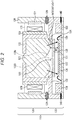
- Fig. 2 is a cross-sectional view illustrating an example configuration of a camera module to which the present technology is applied according to a first embodiment.
- a camera module 110 illustrated in Fig. 2 includes a lens unit 120 and an imaging unit 130.
- the lens unit 120 includes a lens 121, a lens barrel (barrel) 122, a lens holder 123, a coil 124, a spring 125, an actuator unit 126, and a magnet 127.
- the imaging unit 130 includes a substrate 131, a supporting component 132, an IRCF 135, an imaging element 136, and a mounted component 138.
- the lens 121, the lens barrel 122, the lens holder 123, the coil 124, the spring 125, the actuator unit 126, and the magnet 127 in the lens unit 120 correspond to the lens 21, the lens barrel 22, the lens holder 23, the coil 24, the spring 25, the actuator unit 26, and the magnet 27 in the lens unit 20 illustrated in Fig. 1 , respectively.
- the substrate 131, the supporting component 132, the IRCF 135, the imaging element 136, and the mounted component 138 in the imaging unit 130 correspond to the substrate 31, the supporting component 32, the IRCF 35, the imaging element 36, and the mounted component 38 in the imaging unit 30 illustrated in Fig. 1 , respectively.
- the supporting component 132 has an opening 133 through which light from the lens 121 is to pass, the opening 133 being disposed directly above the imaging element 136 (above the effective pixels 137 of the imaging element 136).
- the opening 133 there is disposed a sloped portion 134 inclined in the thickness direction of the supporting component 132, and the supporting component 132 is placed such that the slope of the sloped portion 134 and the lens 121 face each other. Therefore, the supporting component 132 is significantly different from the supporting component 32, which is disposed such that the slope of the sloped portion 34 faces the imaging element 36, in that the supporting component 132 is disposed such that the slope of the sloped portion 134 faces the lens 121.
- the supporting component 132 is formed to have a height enabling the IRCF 135 to be fixed at an appropriate height from the imaging element 136, and the supporting component 132 is bonded to the substrate 131 with an adhesive 140.
- the tip of the sloped portion 34 is located on the upper face (the face facing the lens 21) of the supporting component 32, whereas in the camera module 110, the tip of the sloped portion 134 is located on the lower face (a first face) of the supporting component 132. That is, in the camera module 110, the tip of the sloped portion 134 is located lower than the tip of the sloped portion 34 in the camera module 10. Therefore, in the camera module 110, the lens 121 can be placed lower than the lens 21 in the camera module 10.
- a portion of the opening 133 of the supporting component 132, the portion facing the imaging element 136, is referred to as a lower opening 133D, while a portion of the opening 133 of the supporting component 132, the portion facing the lens 121, is referred to as an upper opening 133U.
- the sloped portion 134 is formed such that the slope faces the lens 121. Therefore, the lens 121 can be placed lower than the lens 21 as long as the upper opening 133U is made larger than the upper opening 33U, even if the opening 133 is formed to be smaller than the opening 33 by making the upper opening 133U smaller than the lower opening 33D and making the lower opening 133D smaller than the upper opening 33U. That is, in the camera module 110, the bottom of the lens 121 (the portion facing the supporting component 132) can be placed closer to the lower face of the supporting component 132 beyond the upper face (a second face) opposite to the lower face of the supporting component 132. In Fig. 2 , the lens 121 is placed such that the bottom of the lens 121 is located between the upper opening 133U (the second face) and the lower opening 133D (the first face).
- the camera module 110 in Fig. 2 has a function of cutting infrared rays separately from the IRCF 135, the camera module 110 can employ, for example, a transparent and plate-like optical component such as a transparent cover film or a transparent cover glass instead of the IRCF 135, and the optical component can be supported by the supporting component 132.
- a transparent and plate-like optical component such as a transparent cover film or a transparent cover glass
- the focus can be adjusted by vertical movement of the lens holder 123 in Fig. 2 , but the lens holder 123 may be fixed to the imaging unit 130 so as not to move in the vertical direction.
- the camera module 110 can be configured without providing the spring 125, the actuator unit 126, and the magnet 127.
- Fig. 3 is a plan view illustrating an example configuration of the imaging unit 130 in Fig. 2 .
- the opening 133 being substantially rectangular is formed in the center of the supporting component 132 being substantially rectangular as viewed from above.
- the sloped portion 134 inclined in the thickness direction of the supporting component 132 is disposed.
- the slope of the sloped portion 134 is formed on the upper face (the face facing the lens 121) of the supporting component 132.
- the IRCF 135 is disposed on the supporting component 132 by being bonded to the lower face (the face facing the imaging element 136) of the supporting component 132 so as to cover (fill) the opening 133.
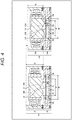
- Fig. 4 is a cross-sectional view for comparing the camera module 10 with the camera module 110.
- the tip of the sloped portion 134 is present lower (closer to the imaging element 136) than the tip of the sloped portion 34 in the camera module 10. Therefore, for example, when the lens 121 of the camera module 110 is at the same position as the lens 21 of the camera module 10, the distance between the tip of the sloped portion 134 and the lens 121 is longer than the distance between the tip of the sloped portion 34 and the lens 21. Therefore, the tip of the sloped portion 134 and the lens 121 in the camera module 110 are less likely to interfere with each other than in the camera module 10.
- the slope of the sloped portion 134 is formed on the upper face (the face facing the lens 121) of the supporting component 132, the size of the upper opening 133U of the opening 133 is inevitably larger than the size A2 of the lower opening 133D.
- the size A2 of the lower opening 133D in the camera module 110 is smaller than the size A1 of the upper opening 33U in the camera module 10 because the size A2 of the lower opening 133D is smaller than the size of the upper opening 133U. Therefore, the opening 133 in the camera module 110 can be made smaller in size than the opening 33 in the camera module 10.
- the IRCF 35 and the IRCF 135 are disposed on the underside of the supporting component 32 and the supporting component 132 so as to cover the opening 33 and the opening 133, respectively. Therefore, the IRCF 35 needs to have a size B1 larger than the lower opening 33D in the camera module 10, whereas the IRCF 135 needs to have a size B2 larger than the size A2 of the lower opening 133D in the camera module 110.
- the slope of the sloped portion 34 is formed on the lower face (the face facing the imaging element 36) of the supporting component 32, the size of the lower opening 33D of the opening 33 is inevitably larger than the size A1 of the upper opening 33U.
- the size of the lower opening 33D is larger than the size A2 of the lower opening 133D in the camera module 110 because the size of the lower opening 33D is larger than the size A1 of the upper opening 33U. That is, the size A2 of the lower opening 133D is smaller than the size of the lower opening 33D. Therefore, the size B2 of the IRCF 135 disposed so as to cover the lower opening 133D can be made smaller than the size B1 of the IRCF 35 disposed so as to cover the lower opening 33D.
- the lens 121 can be placed at a position lower than the lens 21 to be closer to the imaging element 136.
- the height C2 of the lens unit 120 in the camera module 110 can be made less than the height C1 of the lens unit 20 in the camera module 10, and resultingly, the overall height (total height) of the lens unit 120 can be made smaller, and thus the height of the camera module 110 can be reduced.
- the height of the camera module 110 can be reduced more effectively.
- the sloped portion 134 can be formed to have a reflection control structure in which reflection of light coming from the lens 121 is restricted.
- Fig. 5 is a cross-sectional view illustrating a first example configuration of the sloped portion 134.
- (the slope of) the sloped portion 134 in the camera module 110 is formed to have a stair-shaped structure as the reflection control structure.
- the sloped portion 134 is formed into a stair shape as above, the light coming from the lens 121 is incident on the sloped portion 134 at a greater incident angle than in the sloped portion 134 having a continuous (smooth) slope, and thus the light coming from the lens 121 and incident on the sloped portion 134 is more likely to be reflected toward the outside of the lens 121. Therefore, the light reflected from the sloped portion 134 can be inhibited from returning (or being reflected toward) the lens 121. As a result, ghosts and flares caused by the light reflected from the sloped portion 134 can be reduced.
- Fig. 6 is a cross-sectional view for explaining the slope of the first example configuration of the sloped portion 134.
- the sloped portion 134 can be configured such that an inclination angle of the sloped portion 134 with respect to the optical axis of the lens 121 is greater than an angle of light (an incident angle of light) coming from the lens 121 and incident on the tip of the sloped portion 134 with respect to the optical axis of the lens 121.
- the incident angle of the light coming from the lens 121 and incident on the tip of the sloped portion 134 is 38 degrees
- the angle of inclination (hereinafter also referred to as an inclination angle) of the sloped portion 134 with respect to the optical axis of the lens 121 is 60 degrees, which is greater than 38 degrees.
- the riser (upright wall) portion (vertical portion) of the stair of the sloped portion 134 is lower. Therefore, the light reflected from the tread portion (horizontal portion) of the stair of the sloped portion 134 can be inhibited from being further reflected from the riser portion of the stair.
- the occurrence of ghosts and flares caused by secondary reflected light can be suppressed, the secondary reflected light being generated when the light coming from the lens 121 and incident on the sloped portion 134 is reflected from the riser portion of the stair.
- Fig. 7 is a cross-sectional view illustrating a second example configuration of the sloped portion 134.
- the sloped portion 134 of the camera module 110 has, as a reflection control structure, a structure in which an antireflection film that prevents reflection of light is formed on the slope of the sloped portion 134.
- the antireflection film can be formed by, for example, applying an antireflection agent or sticking an antireflection sheet to the slope, or the like.
- sloped portion 134 in Fig. 7 is continuously inclined, but the sloped portion 134 may be formed into a stair shape as illustrated in Fig. 5 and an antireflection film can be formed on the stair-shaped sloped portion 134.
- Fig. 8 is a cross-sectional view for explaining an example of a relationship between the slope of the sloped portion 134 and the lens 121.
- the slope of the sloped portion 134 can be formed into, in a cross-sectional view, a linear shape that is substantially parallel to a tangent line to the face of a lower portion of the lens 121 (a portion facing the supporting component 132).
- the lens 121 can be placed further lower (closer to the imaging element 136). Accordingly, the overall height of the lens unit 120 can be further reduced, and resultingly, the height of the camera module 110 can be further reduced.
- sloped portion 134 in Fig. 8 is formed into a stair shape, but the sloped portion 134 may be formed, for example, to have a continuous slope as illustrated in Fig. 7 .
- Fig. 9 is a cross-sectional view for explaining another example of the relationship between the slope of the sloped portion 134 and the lens 121.
- the slope of the sloped portion 134 can be formed into, in a cross-sectional view, a curved shape (a non-linear shape) that is substantially parallel to the face of a lower portion of the lens 121 (a portion facing the supporting component 132) .
- the lens 121 can be placed further lower. Accordingly, the overall height of the lens unit 120 can be further reduced, and resultingly, the height of the camera module 110 can be further reduced.
- sloped portion 134 in Fig. 9 is formed into a stair shape, but the sloped portion 134 may be formed, for example, to have a continuous slope as illustrated in Fig. 7 .
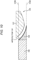
- Fig. 10 is a cross-sectional view for explaining an example of the relationship between the slope of the sloped portion 134 and the lens 121 in a case where the sloped portion 134 is continuously inclined.
- the sloped portion 134 in Fig. 10 is formed to be continuously inclined, and the slope of the sloped portion 134 is formed into, in a cross-sectional view, a curved shape substantially parallel to the face of a lower portion of the lens 121 (a portion facing the supporting component 132). Furthermore, in Fig. 10 , an antireflection film is formed on the sloped portion 134.
- the lens 121 can be placed further lower. Accordingly, the overall height of the lens unit 120 can be further reduced, and resultingly, the height of the camera module 110 can be further reduced.
- Fig. 11 is a cross-sectional view illustrating a third example configuration of the sloped portion 134.
- the sloped portion 134 is formed into a stair shape as in Fig. 5 .
- a resin reservoir 150 which is a groove recessed from the tip of the sloped portion 134, is disposed in the sloped portion 134 on the lower face of the supporting component 132.
- the IRCF 135 is bonded to the lower face of the supporting component 132 across a predetermined adhesion width W.
- Examples of an adhesive that can be employed for bonding the IRCF 135 include a resin such as an ultra violet (UV) adhesive.
- the UV adhesive on the IRCF 135 flowing toward the resin reservoir 150 can be held in the resin reservoir 150. Therefore, the UV adhesive can be prevented from flowing out of the tip of the sloped portion 134 of the supporting component 132.
- Fig. 12 is a cross-sectional view illustrating a fourth example configuration of the sloped portion 134.
- the sloped portion 134 in Fig. 12 is configured in a similar manner to the sloped portion in Fig. 11 showing that the slope is formed into a stair shape, except that the sloped portion 134 is continuously inclined and an antireflection film is formed thereon.
- thermoplastic resin or a thermosetting resin As an adhesive for bonding the IRCF 135 to the supporting component 132, a thermoplastic resin or a thermosetting resin can be employed as well as a UV adhesive. As a thermoplastic resin or thermosetting resin serving as an adhesive, a black thermoplastic resin or thermosetting resin can be employed.
- the resin reservoir 150 disposed at the tip of the sloped portion 134 as illustrated in Figs. 11 and 12 may not necessarily be provided because the light from the lens 121 is prevented from being reflected from the thermoplastic resin or thermosetting resin that flows out of the adhesion between the supporting component 132 and the IRCF 135.
- the sloped portion 134 can be configured without providing the resin reservoir 150.
- FIG. 13 and 14 is a cross-sectional view illustrating an example of adhesion between the supporting component 132 and the IRCF 135 in a case where a black thermoplastic resin or thermosetting resin is employed as an adhesive.
- the supporting component 132 can be configured without disposing the resin reservoir 150 at the tip of the sloped portion 134, and the supporting component 132 can be bonded to the IRCF 135.
- the sloped portion 134 is formed into a stair shape in Fig. 13 , and, in Fig. 14 , the sloped portion 134 is formed to have a continuous slope and an antireflection film is formed on the slope.
- the IRCF 135 is bonded to the lower face of the supporting component 132 with a black thermoplastic resin or thermosetting resin, even if the black thermoplastic resin or thermosetting resin flows out of the tip of the sloped portion 134 of the supporting component 132, the light coming from the lens 121 and incident on the flowing out black thermoplastic resin or thermosetting resin can be prevented from being reflected. Therefore, ghosts and flares caused by the light coming from the lens 121 and reflected from the flowing out black thermoplastic resin or thermosetting resin can be reduced without disposing the resin reservoir 150 illustrated in Figs. 11 and 12 .
- the size of the IRCF 135 can be made smaller if the adhesion width W same to the adhesion width applicable to the case where the resin reservoir 150 is disposed is secured.
- the resin reservoir 150 can be disposed even when a black thermoplastic resin or thermosetting resin is employed as the adhesive.
- the tip of the sloped portion 134 is present lower (closer to the imaging element 136) than the tip of the sloped portion 34 in the camera module 10. Therefore, the distance between the tip of the sloped portion 134 and the bottom portion of the lens 121 is longer, and resultingly, the tip of the sloped portion 134 is less likely to interfere with the bottom portion of the lens 121. Therefore, as compared with the camera module 10, the camera module 110 imposes less strict physical restriction on the position where the lens 121 is placed.
- the lens 121 can be placed on the lower side (closer to the imaging element 136) in the camera module 110 to make the distance between the lens 121 and the imaging element 136 shorter. Therefore, a lens having a shorter BF can be employed as the lens 121. Furthermore, the flexibility in designing the lens 121 can be improved, and a lens having better characteristics (performance) can be designed and employed as the lens 121.
- the overall height of the lens 121 and the height of camera module 110 can be reduced.
- the reduction in height of the camera module 110 can be replaced with additional flexibility in designing the lens to improve the performance of the lens 121.
- the size of the opening 133 in the camera module 110 can be reduced.
- the size of the IRCF 135 disposed to cover the opening 133 (the lower opening 133D of the opening 133) can be made smaller than the size of the IRCF 35 disposed to cover the opening 33 (the lower opening 33D of the opening 33).
- the cost of the IRCF 135 can be reduced.
- the size of the opening 133 in the camera module 110 can be reduced, the light coming from the lens 121 and passing through the opening 133 can be inhibited from entering the outside of the effective pixels 137 of the imaging element 136, such as the gold wire 139 or an electrode pad (not illustrated).
- the effective pixels 137 of the imaging element 136 such as the gold wire 139 or an electrode pad (not illustrated).
- Fig. 15 is a cross-sectional view illustrating an example configuration of a camera module to which the present technology is applied according to a second embodiment.
- the camera module 210 illustrated in Fig. 15 includes the lens unit 120 and an imaging unit 230.
- the camera module 210 is in common with the camera module 110 in Fig. 2 in that the lens unit 120 is included.
- the camera module 210 is different from the camera module 110 in that an imaging unit 230 is disposed in place of the imaging unit 130.
- the imaging unit 230 includes the substrate 131, the supporting component 132, the IRCF 135, the mounted component 138, and an imaging element 236.
- the imaging unit 230 is in common with the imaging unit 130 in Fig. 2 in that the imaging unit 230 includes the substrate 131, the supporting component 132, the IRCF 135, and the mounted component 138.
- the imaging unit 230 is different from the imaging unit 130 in that the imaging element 236 is disposed in place of the imaging element 136.
- the imaging element 236 is a semiconductor device called a wafer level chip size package (WLCSP). On its light-receiving face (the upper side) to receive light, a protective glass 240 is disposed.
- WLCSP wafer level chip size package
- a solder ball 239 serving as an electrical contact with the outside is disposed on the imaging element 236 being a WLCSP.
- the imaging element 236 is mounted on the substrate 131 by flip chip bonding, and is electrically connected to the substrate 131 via the solder ball 239.
- ghosts or flares may be caused by the light passing through the opening 133 and reflected from a side face of the protective glass 240 disposed on the upper side of the imaging element 236, which is a WLCSP.
- the size of the opening 133 in the camera module 210 can be reduced, it is possible to inhibit the light from being reflected from a side face of the protective glass 240; that is, it is possible to inhibit the light from being incident on a side face of the protective glass 240, and thus ghosts and flares caused by reflection of light from a side face of the protective glass 240 can be reduced.
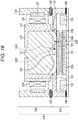
- Fig. 16 is a cross-sectional view illustrating an example configuration of a camera module to which the present technology is applied according to a third embodiment.
- the camera module 310 illustrated in Fig. 16 includes the lens unit 120 and an imaging unit 330.
- the camera module 310 is in common with the camera module 210 in Fig. 15 in that the lens unit 120 is included.
- the camera module 310 is different from the camera module 210 in that the imaging unit 330 is disposed in place of the imaging unit 230.
- the imaging unit 330 includes the substrate 131, the supporting component 132, the IRCF 135, the mounted component 138, the imaging element 236, and a wafer level lens (WLL) 400.
- WLL wafer level lens
- the imaging unit 330 is in common with the imaging unit 230 in Fig. 15 in that the imaging unit 330 includes the substrate 131, the supporting component 132, the IRCF 135, the mounted component 138, and the imaging element 236.
- the imaging unit 330 is different from the imaging unit 230, which does not include the WLL 400, in that the WLL 400 is additionally disposed in the imaging unit 330.
- the WLL 400 is disposed on top of the imaging element 236 (on top of the protective glass 240 disposed on the upper side the imaging element 236).
- a WLCSP provided with a WLL is called a wafer level lens chip size package (WLLCSP). Therefore, the imaging element 236 provided with the WLL 400 constitutes a WLLCSP.
- WLLCSP wafer level lens chip size package
- ghosts or flares may be caused by the light passing through the opening 133 and reflected from a side face of the protective glass 240 included in the WLLCSP or from a side face of the WLL 400.
- the size of the opening 133 in the camera module 310 can be reduced, it is possible to inhibit the light from being reflected from a side face of the protective glass 240 or a side face of the WLL 400; that is, it is possible to inhibit the light from being incident on a side face of the protective glass 240 or of the WLL 400, and thus ghosts and flares caused by reflection of light from a side face of the protective glass 240 or a side face of the WLL 400 can be reduced.
- Fig. 17 is a diagram illustrating example usage of the camera modules 110, 210, and 310 to which the present technology is applied.
- the camera module 110 can be used for various electronic devices that sense light such as visible light, infrared light, ultraviolet light, and X-rays, as described below. The same applies to the camera module 210 in Fig. 15 and the camera module 310 in Fig. 16 .
- Embodiments of the present technology are not limited to the above-described embodiments, and various modifications can be made thereto without departing from the gist of the present technology.
- the present technology may have the following configurations.
Landscapes
- Physics & Mathematics (AREA)
- General Physics & Mathematics (AREA)
- Optics & Photonics (AREA)
- Engineering & Computer Science (AREA)
- Multimedia (AREA)
- Signal Processing (AREA)
- Health & Medical Sciences (AREA)
- Toxicology (AREA)
- Studio Devices (AREA)
- Lens Barrels (AREA)
- Camera Bodies And Camera Details Or Accessories (AREA)
Abstract
Description
- The present technology relates to a camera module, and more particularly, to a camera module that is enabled to have a lower height.
- For example, Patent Document 1 describes a technology for reducing or preventing the occurrence of a ghost in a camera module.
- Patent Document 1: Japanese Patent Application Laid-Open No.
2006-208865 - The camera module described in Patent Document 1 includes a supporting component that supports an infra red cut-off filter (IRCF), and the supporting component has an opening disposed for the purpose of passing light from a lens so that the light passing through the opening is incident on an imaging element.
- In the camera module, a distance needs to be secured between the supporting component and the lens to prevent the supporting component and the lens from interfering with each other. Therefore, it has been difficult to shorten the distance between the lens and the imaging element, and thus a lens having a longer back focus (BF) has been needed. Furthermore, it has been difficult to reduce the height of the camera module.
- The present technology has been made in view of such circumstances, and is intended to enable the camera module to have a lower height.
- A camera module according to the present technology includes a supporting component that includes an opening through which light from a lens collecting the light passes, the supporting component supporting an optical component between the lens and an imaging element that performs photoelectric conversion of the light, the optical component being placed so as to cover the opening and being supported on a side of the supporting component closer to the imaging element, in which the camera module is configured such that: a sloped portion inclined in a thickness direction of the supporting component is disposed around the opening; the supporting component is placed such that a slope of the sloped portion and the lens face each other; and a portion of the lens is placed closer to a first face of the supporting component beyond a second face of the supporting component, the portion facing the supporting component, the optical component being placed on the first face, and the second face being opposite to the first face.
- In the camera module according to the present technology, the supporting component includes an opening through which light from a lens collecting the light passes, the supporting component supporting an optical component between the lens and an imaging element that performs photoelectric conversion of the light, the optical component being placed so as to cover the opening and being supported on a side of the supporting component closer to the imaging element. Around the opening, there is disposed a sloped portion inclined in the thickness direction of the supporting component, and the supporting component is placed such that the slope of the sloped portion and the lens face each other. A portion of the lens is placed closer to a first face of the supporting component beyond a second face of the supporting component, the portion facing the supporting component, the optical component being placed on the first face, and the second face being opposite to the first face.
- According to the present technology, the height of a camera module can be reduced.
- Note that the effects described above are not restrictive, and any of effects described in the present disclosure may be included.
-
-
Fig. 1 is a cross-sectional view illustrating an example configuration of a camera module. -
Fig. 2 is a cross-sectional view illustrating an example configuration of a camera module to which the present technology is applied according to a first embodiment. -
Fig. 3 is a plan view illustrating an example configuration of animaging unit 130 inFig. 2 . -
Fig. 4 is a cross-sectional view for comparing acamera module 10 with acamera module 110. -
Fig. 5 is a cross-sectional view illustrating a first example configuration of a slopedportion 134. -
Fig. 6 is a cross-sectional view for explaining a slope of the first example configuration of the slopedportion 134. -
Fig. 7 is a cross-sectional view illustrating a second example configuration of the slopedportion 134. -
Fig. 8 is a cross-sectional view for explaining an example of a relationship between the slope of the slopedportion 134 and thelens 121. -
Fig. 9 is a cross-sectional view for explaining another example of the relationship between the slope of the slopedportion 134 and thelens 121. -
Fig. 10 is a cross-sectional view for explaining an example of the relationship between the slope of the slopedportion 134 and thelens 121 in a case where the slopedportion 134 is continuously inclined. -
Fig. 11 is a cross-sectional view illustrating a third example configuration of the slopedportion 134. -
Fig. 12 is a cross-sectional view illustrating a fourth example configuration of the slopedportion 134. -
Fig. 13 is a cross-sectional view illustrating an example of adhesion between a supportingcomponent 132 and anIRCF 135 in a case where a black thermoplastic resin or thermosetting resin is employed as an adhesive. -
Fig. 14 is a cross-sectional view illustrating an example of adhesion between the supportingcomponent 132 and theIRCF 135 in a case where a black thermoplastic resin or thermosetting resin is employed as an adhesive. -
Fig. 15 is a cross-sectional view illustrating an example configuration of a camera module to which the present technology is applied according to a second embodiment. -
Fig. 16 is a cross-sectional view illustrating an example configuration of a camera module to which the present technology is applied according to a third embodiment. -
Fig. 17 is a diagram illustrating example usage of thecamera modules -
Fig. 1 is a cross-sectional view illustrating an example configuration of a camera module. - A
camera module 10 illustrated inFig. 1 includes alens unit 20 and animaging unit 30. - The
lens unit 20 includes alens 21, a lens barrel (barrel) 22, alens holder 23, acoil 24, aspring 25, anactuator unit 26, and amagnet 27. Theimaging unit 30 includes asubstrate 31, a supportingcomponent 32, anIRCF 35, animaging element 36, and a mountedcomponent 38. - In the
lens unit 20, thelens 21 is built inside thelens barrel 22, and thelens barrel 22 is held by thelens holder 23. Thelens holder 23 is supported in theactuator unit 26 by thespring 25 so as to be able to move in theactuator unit 26 in the vertical direction in the figure. In thelens unit 20, the focus is adjusted by vertical movement of thelens holder 23. All the cross-sectional views of the camera module herein represent the state where thelens 21 is at "micromechanical end", which means thelens 21 is at a lowest position (closer to the imaging element). - A
coil 24 is disposed on a side face of thelens holder 23. Amagnet 27 is disposed on theactuator unit 26 in a place facing thecoil 24. When a current flows through thecoil 24, thelens holder 23 on which thecoil 24 is disposed is moved in the vertical direction by a magnetic field generated by themagnet 27, that is, thelens 21 moves along the optical axis, to adjust the focus. - The lens unit 20 (the
actuator unit 26 of the lens unit 20) is bonded to the supportingcomponent 32 with anadhesive 28 with the optical axis of thelens 21 aligned with the center ofeffective pixels 37 of theimaging element 36 directly above theimaging element 36 disposed on thesubstrate 31. - The supporting
component 32 has anopening 33 through which light from thelens 21 is to pass, the opening 33 being disposed directly above the imaging element 36 (above theeffective pixels 37 of the imaging element 36). Around the opening 33, there is disposed a slopedportion 34 inclined in the thickness direction of the supportingcomponent 32, and the supportingcomponent 32 is placed such that the slope of thesloped portion 34 and theimaging element 36 face each other. - The supporting
component 32 is formed to have a height that enables theIRCF 35 to be fixed at an appropriate height from theimaging element 36, and the supportingcomponent 32 is bonded to thesubstrate 31 with an adhesive 40. - Here, a portion of the opening 33 of the supporting
component 32, the portion facing theimaging element 36, is referred to as alower opening 33D, while a portion of the opening 33 of the supportingcomponent 32, the portion facing thelens 21, is referred to as anupper opening 33U. - The IRCF 35 is bonded to the lower face of the supporting component 32 (the face facing the imaging element 36) with an adhesive or the like so as to cover the
opening 33 of the supportingcomponent 32. - The
imaging element 36 is disposed on thesubstrate 31 and electrically connected to thesubstrate 31 by a gold wire (wire) 39. - The mounted
component 38 is, for example, a capacitor, a resistor, an electronic component such as an integrated circuit (IC), or the like, and placed at a predetermined position on thesubstrate 31 to be electrically connected. - In the
camera module 10 configured as above, thelens 21 collects light, and the light passes through theopening 33 and illuminates theimaging element 36 via the IRCF 35. On theimaging element 36, the light illuminating theimaging element 36 undergoes photoelectric conversion in theeffective pixels 37, whereby an image is taken. - In the
camera module 10, the slope of the slopedportion 34 is disposed so as to face theimaging element 36. In addition, in thecamera module 10, thelens 21 is placed such that the bottom (lowermost) portion (the portion facing the supporting component 32) of thelens 21 is at the same height as, or slightly higher than, theupper opening 33U, in order that the tip (of the slope) of thesloped portion 34 does not interfere with thelens 21. - In the
camera module 10, thelens 21 needs to be placed so as not to interfere with the tip of thesloped portion 34, which is disposed such that the slope faces theimaging element 36. Thus, it is difficult to bring down thelens 21 to a position lower than the upper opening 33U. Therefore, it is difficult to reduce the height of thecamera module 10. - Furthermore, in the
camera module 10, theopening 33 needs to be formed such that theupper opening 33U has at least a certain size, in order to prevent the tip of the slopedportion 34 from interfering with (the bottom of) thelens 21. Therefore, it is difficult to reduce the size of theopening 33 disposed in the supportingcomponent 32. - As a result, the
camera module 10 is highly prone to ghosts and flares (gold wire ghosts and flares) caused by the light coming from thelens 21, passing through theopening 33, incident on a region other than theeffective pixels 37 of theimaging element 36, for example, incident on thegold wire 39, and reflected from thegold wire 39. - Moreover, in the
camera module 10, since the slopedportion 34 is disposed such that the slope faces theimaging element 36, thelower opening 33D of theopening 33 is inevitably larger than theupper opening 33U in size. Accordingly, theIRCF 35 disposed on the underside of the supportingcomponent 32 so as to cover theopening 33 needs to be large enough, and thecamera module 10 becomes more costly as theIRCF 35 is larger in size. -
Fig. 2 is a cross-sectional view illustrating an example configuration of a camera module to which the present technology is applied according to a first embodiment. - A
camera module 110 illustrated inFig. 2 includes alens unit 120 and animaging unit 130. - The
lens unit 120 includes alens 121, a lens barrel (barrel) 122, alens holder 123, acoil 124, aspring 125, anactuator unit 126, and amagnet 127. Theimaging unit 130 includes asubstrate 131, a supportingcomponent 132, anIRCF 135, animaging element 136, and amounted component 138. - Here, the
lens 121, thelens barrel 122, thelens holder 123, thecoil 124, thespring 125, theactuator unit 126, and themagnet 127 in thelens unit 120 correspond to thelens 21, thelens barrel 22, thelens holder 23, thecoil 24, thespring 25, theactuator unit 26, and themagnet 27 in thelens unit 20 illustrated inFig. 1 , respectively. - Furthermore, the
substrate 131, the supportingcomponent 132, theIRCF 135, theimaging element 136, and the mountedcomponent 138 in theimaging unit 130 correspond to thesubstrate 31, the supportingcomponent 32, theIRCF 35, theimaging element 36, and the mountedcomponent 38 in theimaging unit 30 illustrated inFig. 1 , respectively. - Note that the supporting
component 132 has anopening 133 through which light from thelens 121 is to pass, theopening 133 being disposed directly above the imaging element 136 (above theeffective pixels 137 of the imaging element 136). Around theopening 133, there is disposed a slopedportion 134 inclined in the thickness direction of the supportingcomponent 132, and the supportingcomponent 132 is placed such that the slope of the slopedportion 134 and thelens 121 face each other. Therefore, the supportingcomponent 132 is significantly different from the supportingcomponent 32, which is disposed such that the slope of the slopedportion 34 faces theimaging element 36, in that the supportingcomponent 132 is disposed such that the slope of the slopedportion 134 faces thelens 121. - The supporting
component 132 is formed to have a height enabling theIRCF 135 to be fixed at an appropriate height from theimaging element 136, and the supportingcomponent 132 is bonded to thesubstrate 131 with an adhesive 140. - In the
camera module 10 inFig. 1 , the tip of the slopedportion 34 is located on the upper face (the face facing the lens 21) of the supportingcomponent 32, whereas in thecamera module 110, the tip of the slopedportion 134 is located on the lower face (a first face) of the supportingcomponent 132. That is, in thecamera module 110, the tip of the slopedportion 134 is located lower than the tip of the slopedportion 34 in thecamera module 10. Therefore, in thecamera module 110, thelens 121 can be placed lower than thelens 21 in thecamera module 10. - Here, a portion of the
opening 133 of the supportingcomponent 132, the portion facing theimaging element 136, is referred to as alower opening 133D, while a portion of theopening 133 of the supportingcomponent 132, the portion facing thelens 121, is referred to as anupper opening 133U. - In the
camera module 110, the slopedportion 134 is formed such that the slope faces thelens 121. Therefore, thelens 121 can be placed lower than thelens 21 as long as theupper opening 133U is made larger than theupper opening 33U, even if theopening 133 is formed to be smaller than theopening 33 by making theupper opening 133U smaller than thelower opening 33D and making thelower opening 133D smaller than theupper opening 33U. That is, in thecamera module 110, the bottom of the lens 121 (the portion facing the supporting component 132) can be placed closer to the lower face of the supportingcomponent 132 beyond the upper face (a second face) opposite to the lower face of the supportingcomponent 132. InFig. 2 , thelens 121 is placed such that the bottom of thelens 121 is located between theupper opening 133U (the second face) and thelower opening 133D (the first face). - Note that, in a case where the
camera module 110 inFig. 2 has a function of cutting infrared rays separately from theIRCF 135, thecamera module 110 can employ, for example, a transparent and plate-like optical component such as a transparent cover film or a transparent cover glass instead of theIRCF 135, and the optical component can be supported by the supportingcomponent 132. - Furthermore, the focus can be adjusted by vertical movement of the
lens holder 123 inFig. 2 , but thelens holder 123 may be fixed to theimaging unit 130 so as not to move in the vertical direction. In this case, thecamera module 110 can be configured without providing thespring 125, theactuator unit 126, and themagnet 127. -
Fig. 3 is a plan view illustrating an example configuration of theimaging unit 130 inFig. 2 . - As illustrated in
Fig. 3 , theopening 133 being substantially rectangular is formed in the center of the supportingcomponent 132 being substantially rectangular as viewed from above. Around theopening 133, the slopedportion 134 inclined in the thickness direction of the supportingcomponent 132 is disposed. The slope of the slopedportion 134 is formed on the upper face (the face facing the lens 121) of the supportingcomponent 132. TheIRCF 135 is disposed on the supportingcomponent 132 by being bonded to the lower face (the face facing the imaging element 136) of the supportingcomponent 132 so as to cover (fill) theopening 133. -
Fig. 4 is a cross-sectional view for comparing thecamera module 10 with thecamera module 110. - In the
camera module 110, the tip of the slopedportion 134 is present lower (closer to the imaging element 136) than the tip of the slopedportion 34 in thecamera module 10. Therefore, for example, when thelens 121 of thecamera module 110 is at the same position as thelens 21 of thecamera module 10, the distance between the tip of the slopedportion 134 and thelens 121 is longer than the distance between the tip of the slopedportion 34 and thelens 21. Therefore, the tip of the slopedportion 134 and thelens 121 in thecamera module 110 are less likely to interfere with each other than in thecamera module 10. - Furthermore, in the
camera module 110, since the slope of the slopedportion 134 is formed on the upper face (the face facing the lens 121) of the supportingcomponent 132, the size of theupper opening 133U of theopening 133 is inevitably larger than the size A2 of thelower opening 133D. - Supposing that the size A1 of the
upper opening 33U in thecamera module 10 is same to the size of theupper opening 133U in thecamera module 110, the size A2 of thelower opening 133D in thecamera module 110 is smaller than the size A1 of theupper opening 33U in thecamera module 10 because the size A2 of thelower opening 133D is smaller than the size of theupper opening 133U. Therefore, theopening 133 in thecamera module 110 can be made smaller in size than theopening 33 in thecamera module 10. - Furthermore, the
IRCF 35 and theIRCF 135 are disposed on the underside of the supportingcomponent 32 and the supportingcomponent 132 so as to cover theopening 33 and theopening 133, respectively. Therefore, theIRCF 35 needs to have a size B1 larger than thelower opening 33D in thecamera module 10, whereas theIRCF 135 needs to have a size B2 larger than the size A2 of thelower opening 133D in thecamera module 110. - In the
camera module 10, since the slope of the slopedportion 34 is formed on the lower face (the face facing the imaging element 36) of the supportingcomponent 32, the size of thelower opening 33D of theopening 33 is inevitably larger than the size A1 of theupper opening 33U. - Supposing that the size A2 of the
lower opening 133D is same to the size A1 of theupper opening 33U, the size of thelower opening 33D is larger than the size A2 of thelower opening 133D in thecamera module 110 because the size of thelower opening 33D is larger than the size A1 of theupper opening 33U. That is, the size A2 of thelower opening 133D is smaller than the size of thelower opening 33D. Therefore, the size B2 of theIRCF 135 disposed so as to cover thelower opening 133D can be made smaller than the size B1 of theIRCF 35 disposed so as to cover thelower opening 33D. - Furthermore, supposing that the
lens 121 is disposed in thecamera module 110 at the same position (height) as thelens 21, the tip of the slopedportion 134 and thelens 121 are less likely to interfere with each other than in thecamera module 10, and therefore, thelens 121 can be placed at a position lower than thelens 21 to be closer to theimaging element 136. In this case, the height C2 of thelens unit 120 in thecamera module 110 can be made less than the height C1 of thelens unit 20 in thecamera module 10, and resultingly, the overall height (total height) of thelens unit 120 can be made smaller, and thus the height of thecamera module 110 can be reduced. - Here, in the
lens unit 120, in a case where the lower portion of thelens 121, that is, the portion facing the supportingcomponent 132 in thelens 121, protrudes from the bottom of thelens barrel 122, the height of thecamera module 110 can be reduced more effectively. - An overall configuration of the
camera module 110 has been described above. The following describes in detail a configuration of the slopedportion 134 of the supportingcomponent 132 in thecamera module 110. - The sloped
portion 134 can be formed to have a reflection control structure in which reflection of light coming from thelens 121 is restricted. -
Fig. 5 is a cross-sectional view illustrating a first example configuration of the slopedportion 134. - In
Fig. 5 , (the slope of) the slopedportion 134 in thecamera module 110 is formed to have a stair-shaped structure as the reflection control structure. - Since the sloped
portion 134 is formed into a stair shape as above, the light coming from thelens 121 is incident on the slopedportion 134 at a greater incident angle than in the slopedportion 134 having a continuous (smooth) slope, and thus the light coming from thelens 121 and incident on the slopedportion 134 is more likely to be reflected toward the outside of thelens 121. Therefore, the light reflected from the slopedportion 134 can be inhibited from returning (or being reflected toward) thelens 121. As a result, ghosts and flares caused by the light reflected from the slopedportion 134 can be reduced. -
Fig. 6 is a cross-sectional view for explaining the slope of the first example configuration of the slopedportion 134. - The sloped
portion 134 can be configured such that an inclination angle of the slopedportion 134 with respect to the optical axis of thelens 121 is greater than an angle of light (an incident angle of light) coming from thelens 121 and incident on the tip of the slopedportion 134 with respect to the optical axis of thelens 121. - In
Fig. 6 , the incident angle of the light coming from thelens 121 and incident on the tip of the slopedportion 134 is 38 degrees, whereas the angle of inclination (hereinafter also referred to as an inclination angle) of the slopedportion 134 with respect to the optical axis of thelens 121 is 60 degrees, which is greater than 38 degrees. - As described above, in a case where the inclination angle of the sloped
portion 134 formed into a stair shape is larger than the incident angle of the light coming from thelens 121 and incident on the tip of the slopedportion 134, the riser (upright wall) portion (vertical portion) of the stair of the slopedportion 134 is lower. Therefore, the light reflected from the tread portion (horizontal portion) of the stair of the slopedportion 134 can be inhibited from being further reflected from the riser portion of the stair. As a result, the occurrence of ghosts and flares caused by secondary reflected light can be suppressed, the secondary reflected light being generated when the light coming from thelens 121 and incident on the slopedportion 134 is reflected from the riser portion of the stair. -
Fig. 7 is a cross-sectional view illustrating a second example configuration of the slopedportion 134. - In
Fig. 7 , the slopedportion 134 of thecamera module 110 has, as a reflection control structure, a structure in which an antireflection film that prevents reflection of light is formed on the slope of the slopedportion 134. - The antireflection film can be formed by, for example, applying an antireflection agent or sticking an antireflection sheet to the slope, or the like.
- In a case where an antireflection film is formed on the sloped
portion 134 as above, the light coming from thelens 121 and incident on the slopedportion 134 can be prevented from being reflected. Therefore, ghosts and flares caused by the light reflected from the slopedportion 134 can be reduced. - Note that the sloped
portion 134 inFig. 7 is continuously inclined, but the slopedportion 134 may be formed into a stair shape as illustrated inFig. 5 and an antireflection film can be formed on the stair-shapedsloped portion 134. -
Fig. 8 is a cross-sectional view for explaining an example of a relationship between the slope of the slopedportion 134 and thelens 121. - The slope of the sloped
portion 134 can be formed into, in a cross-sectional view, a linear shape that is substantially parallel to a tangent line to the face of a lower portion of the lens 121 (a portion facing the supporting component 132). - In a case where the slope of the sloped
portion 134 is formed into a shape substantially parallel to a tangent line to the face of a lower portion of thelens 121 as above, thelens 121 can be placed further lower (closer to the imaging element 136). Accordingly, the overall height of thelens unit 120 can be further reduced, and resultingly, the height of thecamera module 110 can be further reduced. - Note that the sloped
portion 134 inFig. 8 is formed into a stair shape, but the slopedportion 134 may be formed, for example, to have a continuous slope as illustrated inFig. 7 . -
Fig. 9 is a cross-sectional view for explaining another example of the relationship between the slope of the slopedportion 134 and thelens 121. - The slope of the sloped
portion 134 can be formed into, in a cross-sectional view, a curved shape (a non-linear shape) that is substantially parallel to the face of a lower portion of the lens 121 (a portion facing the supporting component 132) . - In a case where the slope of the sloped
portion 134 is formed into a shape substantially parallel to the face of a lower portion of thelens 121 as above, thelens 121 can be placed further lower. Accordingly, the overall height of thelens unit 120 can be further reduced, and resultingly, the height of thecamera module 110 can be further reduced. - Note that the sloped
portion 134 inFig. 9 is formed into a stair shape, but the slopedportion 134 may be formed, for example, to have a continuous slope as illustrated inFig. 7 . -
Fig. 10 is a cross-sectional view for explaining an example of the relationship between the slope of the slopedportion 134 and thelens 121 in a case where the slopedportion 134 is continuously inclined. - The sloped
portion 134 inFig. 10 is formed to be continuously inclined, and the slope of the slopedportion 134 is formed into, in a cross-sectional view, a curved shape substantially parallel to the face of a lower portion of the lens 121 (a portion facing the supporting component 132). Furthermore, inFig. 10 , an antireflection film is formed on the slopedportion 134. - In a case where the slope of the sloped
portion 134 is formed into a shape substantially parallel to the face of a lower portion of thelens 121 as above, thelens 121 can be placed further lower. Accordingly, the overall height of thelens unit 120 can be further reduced, and resultingly, the height of thecamera module 110 can be further reduced. -
Fig. 11 is a cross-sectional view illustrating a third example configuration of the slopedportion 134. - In
Fig. 11 , the slopedportion 134 is formed into a stair shape as inFig. 5 . - Furthermore, in
Fig. 11 , aresin reservoir 150, which is a groove recessed from the tip of the slopedportion 134, is disposed in the slopedportion 134 on the lower face of the supportingcomponent 132. - The
IRCF 135 is bonded to the lower face of the supportingcomponent 132 across a predetermined adhesion width W. Examples of an adhesive that can be employed for bonding theIRCF 135 include a resin such as an ultra violet (UV) adhesive. - In a case where the
resin reservoir 150 is disposed in the slopedportion 134 as above, when theIRCF 135 is bonded to the lower face of the supportingcomponent 132 with an UV adhesive, the UV adhesive on theIRCF 135 flowing toward theresin reservoir 150 can be held in theresin reservoir 150. Therefore, the UV adhesive can be prevented from flowing out of the tip of the slopedportion 134 of the supportingcomponent 132. - As a result, it is made possible to suppress reflection of the light coming from the
lens 121 and reflected from the UV adhesive, if any, that flows out of the tip of the slopedportion 134 of the supportingcomponent 132, and to reduce ghosts and flares caused by the light reflected from the UV adhesive. -
Fig. 12 is a cross-sectional view illustrating a fourth example configuration of the slopedportion 134. - Note that the portions in the figure corresponding to the portions in
Fig. 11 are given the same reference numerals, and descriptions of these portions are omitted below as appropriate. - The sloped
portion 134 inFig. 12 is configured in a similar manner to the sloped portion inFig. 11 showing that the slope is formed into a stair shape, except that the slopedportion 134 is continuously inclined and an antireflection film is formed thereon. - Therefore, as in
Fig. 11 , ghosts and flares caused by reflection of light from the UV adhesive can be reduced inFig. 12 . - As an adhesive for bonding the
IRCF 135 to the supportingcomponent 132, a thermoplastic resin or a thermosetting resin can be employed as well as a UV adhesive. As a thermoplastic resin or thermosetting resin serving as an adhesive, a black thermoplastic resin or thermosetting resin can be employed. - In a case where a black thermoplastic resin or thermosetting resin is employed as an adhesive for bonding the
IRCF 135 to the supportingcomponent 132, theresin reservoir 150 disposed at the tip of the slopedportion 134 as illustrated inFigs. 11 and12 may not necessarily be provided because the light from thelens 121 is prevented from being reflected from the thermoplastic resin or thermosetting resin that flows out of the adhesion between the supportingcomponent 132 and theIRCF 135. - That is, in a case where a black thermoplastic resin or thermosetting resin is employed as an adhesive for bonding the
IRCF 135 to the supportingcomponent 132, the slopedportion 134 can be configured without providing theresin reservoir 150. - Each of
Figs. 13 and14 is a cross-sectional view illustrating an example of adhesion between the supportingcomponent 132 and theIRCF 135 in a case where a black thermoplastic resin or thermosetting resin is employed as an adhesive. - In a case where a black thermoplastic resin or thermosetting resin is employed as the adhesive, the supporting
component 132 can be configured without disposing theresin reservoir 150 at the tip of the slopedportion 134, and the supportingcomponent 132 can be bonded to theIRCF 135. - Note that the sloped
portion 134 is formed into a stair shape inFig. 13 , and, inFig. 14 , the slopedportion 134 is formed to have a continuous slope and an antireflection film is formed on the slope. - In a case where the
IRCF 135 is bonded to the lower face of the supportingcomponent 132 with a black thermoplastic resin or thermosetting resin, even if the black thermoplastic resin or thermosetting resin flows out of the tip of the slopedportion 134 of the supportingcomponent 132, the light coming from thelens 121 and incident on the flowing out black thermoplastic resin or thermosetting resin can be prevented from being reflected. Therefore, ghosts and flares caused by the light coming from thelens 121 and reflected from the flowing out black thermoplastic resin or thermosetting resin can be reduced without disposing theresin reservoir 150 illustrated inFigs. 11 and12 . - Furthermore, as compared with the case where the
resin reservoir 150 is disposed, a greater adhesion width W for theIRCF 135 can be secured without disposing theresin reservoir 150. Therefore, in a case where theresin reservoir 150 is not disposed, the size of theIRCF 135 can be made smaller if the adhesion width W same to the adhesion width applicable to the case where theresin reservoir 150 is disposed is secured. - Note that the
resin reservoir 150 can be disposed even when a black thermoplastic resin or thermosetting resin is employed as the adhesive. - As described above, in a case where the
lens 121 in thecamera module 110 is placed at the same position (height) as thelens 21 in thecamera module 10 while the supportingcomponent 132 is placed such that the slope of the slopedportion 134 faces thelens 121, the tip of the slopedportion 134 is present lower (closer to the imaging element 136) than the tip of the slopedportion 34 in thecamera module 10. Therefore, the distance between the tip of the slopedportion 134 and the bottom portion of thelens 121 is longer, and resultingly, the tip of the slopedportion 134 is less likely to interfere with the bottom portion of thelens 121. Therefore, as compared with thecamera module 10, thecamera module 110 imposes less strict physical restriction on the position where thelens 121 is placed. - As a result, the
lens 121 can be placed on the lower side (closer to the imaging element 136) in thecamera module 110 to make the distance between thelens 121 and theimaging element 136 shorter. Therefore, a lens having a shorter BF can be employed as thelens 121. Furthermore, the flexibility in designing thelens 121 can be improved, and a lens having better characteristics (performance) can be designed and employed as thelens 121. - Moreover, the overall height of the
lens 121 and the height ofcamera module 110 can be reduced. - Note that the reduction in height of the
camera module 110 can be replaced with additional flexibility in designing the lens to improve the performance of thelens 121. - Furthermore, the size of the
opening 133 in thecamera module 110 can be reduced. In other words, it is possible to make the size of thelower opening 133D in thecamera module 110 smaller than the size of thelower opening 33D in thecamera module 10. Therefore, the size of theIRCF 135 disposed to cover the opening 133 (thelower opening 133D of the opening 133) can be made smaller than the size of theIRCF 35 disposed to cover the opening 33 (thelower opening 33D of the opening 33). As a result, the cost of theIRCF 135 can be reduced. - Furthermore, since the size of the
opening 133 in thecamera module 110 can be reduced, the light coming from thelens 121 and passing through theopening 133 can be inhibited from entering the outside of theeffective pixels 137 of theimaging element 136, such as thegold wire 139 or an electrode pad (not illustrated). As a result, it is made possible to reduce stray light coming from thelens 121 and reflected from the outside of theeffective pixels 137 of theimaging element 136, and thus ghosts and flares caused by such stray light can be reduced. -
Fig. 15 is a cross-sectional view illustrating an example configuration of a camera module to which the present technology is applied according to a second embodiment. - Note that the portions in the figure corresponding to the portions in
Fig. 2 are given the same reference numerals, and descriptions of these portions are omitted below as appropriate. - The
camera module 210 illustrated inFig. 15 includes thelens unit 120 and animaging unit 230. - Therefore, the
camera module 210 is in common with thecamera module 110 inFig. 2 in that thelens unit 120 is included. - However, the
camera module 210 is different from thecamera module 110 in that animaging unit 230 is disposed in place of theimaging unit 130. - The
imaging unit 230 includes thesubstrate 131, the supportingcomponent 132, theIRCF 135, the mountedcomponent 138, and animaging element 236. - Therefore, the
imaging unit 230 is in common with theimaging unit 130 inFig. 2 in that theimaging unit 230 includes thesubstrate 131, the supportingcomponent 132, theIRCF 135, and the mountedcomponent 138. - However, the
imaging unit 230 is different from theimaging unit 130 in that theimaging element 236 is disposed in place of theimaging element 136. - The
imaging element 236 is a semiconductor device called a wafer level chip size package (WLCSP). On its light-receiving face (the upper side) to receive light, aprotective glass 240 is disposed. - On the
imaging element 236 being a WLCSP, asolder ball 239 serving as an electrical contact with the outside is disposed. Theimaging element 236 is mounted on thesubstrate 131 by flip chip bonding, and is electrically connected to thesubstrate 131 via thesolder ball 239. - In the
camera module 210, ghosts or flares may be caused by the light passing through theopening 133 and reflected from a side face of theprotective glass 240 disposed on the upper side of theimaging element 236, which is a WLCSP. However, since the size of theopening 133 in thecamera module 210 can be reduced, it is possible to inhibit the light from being reflected from a side face of theprotective glass 240; that is, it is possible to inhibit the light from being incident on a side face of theprotective glass 240, and thus ghosts and flares caused by reflection of light from a side face of theprotective glass 240 can be reduced. -
Fig. 16 is a cross-sectional view illustrating an example configuration of a camera module to which the present technology is applied according to a third embodiment. - Note that the portions in the figure corresponding to the portions in
Fig. 15 are given the same reference numerals, and descriptions of these portions are omitted below as appropriate. - The
camera module 310 illustrated inFig. 16 includes thelens unit 120 and animaging unit 330. - Therefore, the
camera module 310 is in common with thecamera module 210 inFig. 15 in that thelens unit 120 is included. - However, the
camera module 310 is different from thecamera module 210 in that theimaging unit 330 is disposed in place of theimaging unit 230. - The
imaging unit 330 includes thesubstrate 131, the supportingcomponent 132, theIRCF 135, the mountedcomponent 138, theimaging element 236, and a wafer level lens (WLL) 400. - Therefore, the
imaging unit 330 is in common with theimaging unit 230 inFig. 15 in that theimaging unit 330 includes thesubstrate 131, the supportingcomponent 132, theIRCF 135, the mountedcomponent 138, and theimaging element 236. - However, the
imaging unit 330 is different from theimaging unit 230, which does not include theWLL 400, in that theWLL 400 is additionally disposed in theimaging unit 330. - The
WLL 400 is disposed on top of the imaging element 236 (on top of theprotective glass 240 disposed on the upper side the imaging element 236). - A WLCSP provided with a WLL is called a wafer level lens chip size package (WLLCSP). Therefore, the
imaging element 236 provided with theWLL 400 constitutes a WLLCSP. - In the
camera module 310, ghosts or flares may be caused by the light passing through theopening 133 and reflected from a side face of theprotective glass 240 included in the WLLCSP or from a side face of theWLL 400. However, since the size of theopening 133 in thecamera module 310 can be reduced, it is possible to inhibit the light from being reflected from a side face of theprotective glass 240 or a side face of theWLL 400; that is, it is possible to inhibit the light from being incident on a side face of theprotective glass 240 or of theWLL 400, and thus ghosts and flares caused by reflection of light from a side face of theprotective glass 240 or a side face of theWLL 400 can be reduced. - <Example usage of camera module>
-
Fig. 17 is a diagram illustrating example usage of thecamera modules - For example, the
camera module 110 can be used for various electronic devices that sense light such as visible light, infrared light, ultraviolet light, and X-rays, as described below. The same applies to thecamera module 210 inFig. 15 and thecamera module 310 inFig. 16 . - Electronic devices that take images for appreciation, such as digital cameras and mobile devices with camera functions
- Electronic devices used for traffic for the purpose of automatic stop and other safe driving, recognition of the state of a driver, and the like, such as car-mounted sensors that take images of the front, rear, surroundings, and inside of a car, monitoring cameras that monitor running vehicles and roads, distance measuring sensors that measure the distance between vehicles, and the like
- Electronic devices used for home appliances for the purpose of taking images of the user's gesture and operating the appliance in accordance with the gesture, such as TVs, refrigerators, and air conditioners
- Electronic devices used for medical care and healthcare, such as endoscopes, electron microscopes, and devices that receive infrared light to image blood vessels
- Electronic devices used for security, such as monitoring cameras for security and cameras for person authentication
- Electronic devices used for beauty care, such as skin measuring devices that take images of skins and microscopes that take images of scalp
- Electronic devices used for sports, such as action cameras and wearable cameras for sports application and the like
- Electronic devices used for agriculture, such as cameras for monitoring the condition of farms and crops
- Embodiments of the present technology are not limited to the above-described embodiments, and various modifications can be made thereto without departing from the gist of the present technology.
- Note that the effects described herein are examples only and are not restrictive, and other effects not described herein may be provided.
- The present technology may have the following configurations.
- (1) A camera module including:
a supporting component that includes an opening through which light from a lens collecting the light passes, the supporting component supporting an optical component between the lens and an imaging element that performs photoelectric conversion of the light, the optical component being placed so as to cover the opening and being supported on a side of the supporting component closer to the imaging element, in which the camera module is configured such that:- a sloped portion inclined in a thickness direction of the supporting component is disposed around the opening;
- the supporting component is placed so that a slope of the sloped portion and the lens face each other; and
- a portion of the lens is placed closer to a first face of the supporting component beyond a second face of the supporting component, the portion facing the supporting component, the optical component being placed on the first face, and the second face being opposite to the first face.
- (2) The camera module according to (1), in which
the sloped portion includes a reflection control structure in which reflection of the light coming from the lens is controlled. - (3) The camera module according to (2), in which
the sloped portion includes a stair shape as the reflection control structure. - (4) The camera module according to (3), in which
an inclination angle of the sloped portion with respect to an optical axis of the lens is greater than an angle of the light with respect to the optical axis, the light coming from the lens and being incident on a tip of the sloped portion. - (5) The camera module according to (2), in which
as the reflection control structure, an antireflection film that prevents reflection of light is formed on the sloped portion. - (6) The camera module according to any one of (1) to (5), in which
the sloped portion includes a shape parallel to a tangent line to a face of a portion of the lens, the portion facing the supporting component. - (7) The camera module according to any one of (1) to (5), in which
the sloped portion includes a shape parallel to a face of a portion of the lens, the portion facing the supporting component. - (8) The camera module according to any one of (1) to (7), in which
a groove recessed from a tip of the sloped portion is disposed on the first face of the supporting component. - (9) The camera module according to (8), in which
the optical component is bonded to the first face of the supporting component with an adhesive. - (10) The camera module according to any one of (1) to (9), in which
the optical component is bonded to the first face of the supporting component with a thermoplastic resin or a thermosetting resin. - (11) The camera module according to any one of (1) to (10), in which
the optical component includes an infrared cut-off filter (IRCF) . -
- 10
- Camera module
- 20
- Lens unit
- 21
- Lens
- 22
- Lens barrel
- 23
- Lens holder
- 24
- Coil
- 25
- Spring
- 26
- Actuator unit
- 27
- Magnet
- 28
- Adhesive
- 30
- Imaging unit
- 31
- Substrate
- 32
- Supporting component
- 33
- Opening
- 33U
- Upper opening
- 33D
- Lower opening
- 34
- Sloped portion
- 35
- IRCF
- 36
- Imaging element
- 37
- Effective pixels
- 38
- Mounted component
- 39
- Gold wire
- 40
- Adhesive
- 110
- Camera module
- 120
- Lens unit
- 121
- Lens
- 122
- Lens barrel
- 123
- Lens holder
- 124
- Coil
- 125
- Spring
- 126
- Actuator unit
- 127
- Magnet
- 128
- Adhesive
- 130
- Imaging unit
- 131
- Substrate
- 132
- Supporting component
- 133
- Opening
- 133U
- Upper opening
- 133D
- Lower opening
- 134
- Sloped portion
- 135
- IRCF
- 136
- Imaging element
- 137
- Effective pixels
- 138
- Mounted component
- 139
- Gold wire
- 140
- Adhesive
- 150
- Resin reservoir
- 210
- Camera module
- 230
- Imaging unit
- 236
- Imaging element
- 239
- Solder ball
- 240
- Protective glass
- 310
- Camera module
- 400
- WLL
Claims (11)
- A camera module comprising:a supporting component that includes an opening through which light from a lens collecting the light passes, the supporting component supporting an optical component between the lens and an imaging element that performs photoelectric conversion of the light, the optical component being placed so as to cover the opening and being supported on a side of the supporting component closer to the imaging element, whereinthe camera module is configured such that:a sloped portion inclined in a thickness direction of the supporting component is disposed around the opening;the supporting component is placed such that a slope of the sloped portion and the lens face each other; anda portion of the lens is placed closer to a first face of the supporting component beyond a second face of the supporting component, the portion facing the supporting component, the optical component being placed on the first face, and the second face being opposite to the first face.
- The camera module according to claim 1, wherein
the sloped portion includes a reflection control structure in which reflection of the light coming from the lens is controlled. - The camera module according to claim 2, wherein
the sloped portion includes a stair shape as the reflection control structure. - The camera module according to claim 3, wherein
an inclination angle of the sloped portion with respect to an optical axis of the lens is greater than an angle of the light with respect to the optical axis, the light coming from the lens and being incident on a tip of the sloped portion. - The camera module according to claim 2, wherein
as the reflection control structure, an antireflection film that prevents reflection of light is formed on the sloped portion. - The camera module according to claim 1, wherein
the sloped portion includes a shape parallel to a tangent line to a face of a portion of the lens, the portion facing the supporting component. - The camera module according to claim 1, wherein
the sloped portion includes a shape parallel to a face of a portion of the lens, the portion facing the supporting component. - The camera module according to claim 1, wherein
a groove recessed from a tip of the sloped portion is disposed on the first face of the supporting component. - The camera module according to claim 8, wherein
the optical component is bonded to the first face of the supporting component with an adhesive. - The camera module according to claim 1, wherein
the optical component is bonded to the first face of the supporting component with a thermoplastic resin or a thermosetting resin. - The camera module according to claim 1, wherein
the optical component includes an infrared cut-off filter (IRCF) .
Applications Claiming Priority (2)
| Application Number | Priority Date | Filing Date | Title |
|---|---|---|---|
| JP2018033206A JP2019148698A (en) | 2018-02-27 | 2018-02-27 | Camera module |
| PCT/JP2019/004932 WO2019167607A1 (en) | 2018-02-27 | 2019-02-13 | Camera module |
Publications (3)
| Publication Number | Publication Date |
|---|---|
| EP3761097A1 true EP3761097A1 (en) | 2021-01-06 |
| EP3761097A4 EP3761097A4 (en) | 2021-04-07 |
| EP3761097B1 EP3761097B1 (en) | 2025-09-03 |
Family
ID=67806111
Family Applications (1)
| Application Number | Title | Priority Date | Filing Date |
|---|---|---|---|
| EP19760433.3A Active EP3761097B1 (en) | 2018-02-27 | 2019-02-13 | Camera module |
Country Status (5)
| Country | Link |
|---|---|
| US (1) | US11960139B2 (en) |
| EP (1) | EP3761097B1 (en) |
| JP (1) | JP2019148698A (en) |
| CN (1) | CN111656239A (en) |
| WO (1) | WO2019167607A1 (en) |
Families Citing this family (4)
| Publication number | Priority date | Publication date | Assignee | Title |
|---|---|---|---|---|
| JP7277268B2 (en) * | 2019-06-06 | 2023-05-18 | キヤノン株式会社 | Optical element, optical equipment, imaging device, and method for manufacturing optical element |
| CN113114899B (en) | 2021-04-15 | 2022-02-25 | 维沃移动通信有限公司 | Imaging device and electronic apparatus |
| EP4277244B1 (en) * | 2021-06-04 | 2025-11-12 | Samsung Electronics Co., Ltd. | Electronic device comprising window for optical module |
| US20230411540A1 (en) * | 2022-06-16 | 2023-12-21 | Taiwan Semiconductor Manufacturing Company Limited | Semiconductor device and method of making |
Family Cites Families (10)
| Publication number | Priority date | Publication date | Assignee | Title |
|---|---|---|---|---|
| JP4365743B2 (en) | 2004-07-27 | 2009-11-18 | 富士通マイクロエレクトロニクス株式会社 | Imaging device |
| JP2006208865A (en) | 2005-01-28 | 2006-08-10 | Mitsumi Electric Co Ltd | The camera module |
| WO2007097158A1 (en) * | 2006-02-20 | 2007-08-30 | Nitto Denko Corporation | Liquid crystal panel and liquid crystal display employing same |
| JP2007233262A (en) * | 2006-03-03 | 2007-09-13 | Konica Minolta Opto Inc | Imaging device and portable terminal |
| JP4999508B2 (en) * | 2007-03-20 | 2012-08-15 | 日立マクセル株式会社 | Lens unit |
| JP4764942B2 (en) * | 2008-09-25 | 2011-09-07 | シャープ株式会社 | Optical element, optical element wafer, optical element wafer module, optical element module, optical element module manufacturing method, electronic element wafer module, electronic element module manufacturing method, electronic element module, and electronic information device |
| JP2012247365A (en) * | 2011-05-30 | 2012-12-13 | Three M Innovative Properties Co | Film laminate body for pressure sensitive fingerprint sensor, and pressure sensitive fingerprint sensor using such film laminate body |
| JP2014096622A (en) * | 2012-11-07 | 2014-05-22 | Konica Minolta Inc | Camera module and portable terminal |
| JP2015099262A (en) * | 2013-11-19 | 2015-05-28 | ソニー株式会社 | Solid-state imaging device, camera module, and electronic device |
| JP6430206B2 (en) | 2014-10-16 | 2018-11-28 | 富士フイルム株式会社 | The camera module |
-
2018
- 2018-02-27 JP JP2018033206A patent/JP2019148698A/en active Pending
-
2019
- 2019-02-13 CN CN201980010291.3A patent/CN111656239A/en active Pending
- 2019-02-13 EP EP19760433.3A patent/EP3761097B1/en active Active
- 2019-02-13 US US16/970,773 patent/US11960139B2/en active Active
- 2019-02-13 WO PCT/JP2019/004932 patent/WO2019167607A1/en not_active Ceased
Also Published As
| Publication number | Publication date |
|---|---|
| EP3761097B1 (en) | 2025-09-03 |
| US20210096318A1 (en) | 2021-04-01 |
| US11960139B2 (en) | 2024-04-16 |
| JP2019148698A (en) | 2019-09-05 |
| CN111656239A (en) | 2020-09-11 |
| WO2019167607A1 (en) | 2019-09-06 |
| EP3761097A4 (en) | 2021-04-07 |
Similar Documents
| Publication | Publication Date | Title |
|---|---|---|
| EP3761097B1 (en) | Camera module | |
| US11774708B2 (en) | Lens system, fingerprint identification apparatus and terminal device | |
| US11366290B2 (en) | Lens system, fingerprint identification apparatus and terminal device | |
| US10763286B2 (en) | Semiconductor device, manufacturing method thereof, and electronic apparatus | |
| CN115516846B (en) | Distance measuring camera device | |
| US11262485B2 (en) | Image sensor and electronic apparatus | |
| WO2020133344A1 (en) | Fingerprint identification device and electronic equipment | |
| US20180286902A1 (en) | Solid-state imaging device package and manufacturing method, and electronic apparatus | |
| CN209640878U (en) | Fingerprint identification device and electronic equipment | |
| WO2020146985A1 (en) | Fingerprint recognition apparatus and electronic device | |
| CN107683526A (en) | Imaging sensor and electronic installation | |
| CN108885696A (en) | Under-screen biometric devices and electronic devices | |
| CN108701696A (en) | Glass intermediary layer module, imaging device and electronic equipment | |
| WO2020243934A1 (en) | Optical image acquisition apparatus and electronic device | |
| KR102354606B1 (en) | Camera module and optical apparatus | |
| CN208888838U (en) | Optical image acquisition unit, optical image acquisition device, and electronic equipment | |
| CN100481471C (en) | Image forming apparatus and setting method thereof | |
| US20180359437A1 (en) | Solid-state imaging device, manufacturing method of solid-state imaging device, and electronic device | |
| US20200303438A1 (en) | Solid-state imaging element, manufacturing method, and electronic apparatus | |
| US20190305031A1 (en) | Solid-state imaging element, imaging device, and electronic device | |
| CN208589448U (en) | Chip-packaging structure and terminal device | |
| US11356583B2 (en) | Image capturing apparatus, electronic equipment and terminal | |
| CN100448014C (en) | Image sensing chip set | |
| US20170371124A1 (en) | Imaging apparatus and electronic device | |
| WO2025153682A1 (en) | Camera modules incorporating metasurfaces |
Legal Events
| Date | Code | Title | Description |
|---|---|---|---|
| STAA | Information on the status of an ep patent application or granted ep patent |
Free format text: STATUS: THE INTERNATIONAL PUBLICATION HAS BEEN MADE |
|
| PUAI | Public reference made under article 153(3) epc to a published international application that has entered the european phase |
Free format text: ORIGINAL CODE: 0009012 |
|
| STAA | Information on the status of an ep patent application or granted ep patent |
Free format text: STATUS: REQUEST FOR EXAMINATION WAS MADE |
|
| 17P | Request for examination filed |
Effective date: 20200716 |
|
| AK | Designated contracting states |
Kind code of ref document: A1 Designated state(s): AL AT BE BG CH CY CZ DE DK EE ES FI FR GB GR HR HU IE IS IT LI LT LU LV MC MK MT NL NO PL PT RO RS SE SI SK SM TR |
|
| AX | Request for extension of the european patent |
Extension state: BA ME |
|
| A4 | Supplementary search report drawn up and despatched |
Effective date: 20210304 |
|
| RIC1 | Information provided on ipc code assigned before grant |
Ipc: H04N 5/225 20060101ALI20210226BHEP Ipc: G03B 17/02 20210101ALI20210226BHEP Ipc: G02B 7/02 20210101AFI20210226BHEP |
|
| DAV | Request for validation of the european patent (deleted) | ||
| DAX | Request for extension of the european patent (deleted) | ||
| STAA | Information on the status of an ep patent application or granted ep patent |
Free format text: STATUS: EXAMINATION IS IN PROGRESS |
|
| 17Q | First examination report despatched |
Effective date: 20230628 |
|
| REG | Reference to a national code |
Ref country code: DE Free format text: PREVIOUS MAIN CLASS: G02B0007020000 Ref country code: DE Ref legal event code: R079 Ref document number: 602019075166 Country of ref document: DE Free format text: PREVIOUS MAIN CLASS: G02B0007020000 Ipc: G03B0017020000 |
|
| GRAP | Despatch of communication of intention to grant a patent |
Free format text: ORIGINAL CODE: EPIDOSNIGR1 |
|
| STAA | Information on the status of an ep patent application or granted ep patent |
Free format text: STATUS: GRANT OF PATENT IS INTENDED |
|
| RIC1 | Information provided on ipc code assigned before grant |
Ipc: H04N 23/57 20230101ALI20250317BHEP Ipc: H04N 23/55 20230101ALI20250317BHEP Ipc: G03B 30/00 20210101ALI20250317BHEP Ipc: G02B 13/00 20060101ALI20250317BHEP Ipc: G03B 17/02 20210101AFI20250317BHEP |
|
| INTG | Intention to grant announced |
Effective date: 20250403 |
|
| GRAS | Grant fee paid |
Free format text: ORIGINAL CODE: EPIDOSNIGR3 |
|
| GRAA | (expected) grant |
Free format text: ORIGINAL CODE: 0009210 |
|
| STAA | Information on the status of an ep patent application or granted ep patent |
Free format text: STATUS: THE PATENT HAS BEEN GRANTED |
|
| AK | Designated contracting states |
Kind code of ref document: B1 Designated state(s): AL AT BE BG CH CY CZ DE DK EE ES FI FR GB GR HR HU IE IS IT LI LT LU LV MC MK MT NL NO PL PT RO RS SE SI SK SM TR |
|
| P01 | Opt-out of the competence of the unified patent court (upc) registered |
Free format text: CASE NUMBER: UPC_APP_2113_3761097/2025 Effective date: 20250731 |
|
| REG | Reference to a national code |
Ref country code: CH Ref legal event code: EP |
|
| REG | Reference to a national code |
Ref country code: DE Ref legal event code: R096 Ref document number: 602019075166 Country of ref document: DE |
|
| REG | Reference to a national code |
Ref country code: IE Ref legal event code: FG4D |
|
| REG | Reference to a national code |
Ref country code: NL Ref legal event code: MP Effective date: 20250903 |
|
| PG25 | Lapsed in a contracting state [announced via postgrant information from national office to epo] |
Ref country code: NO Free format text: LAPSE BECAUSE OF FAILURE TO SUBMIT A TRANSLATION OF THE DESCRIPTION OR TO PAY THE FEE WITHIN THE PRESCRIBED TIME-LIMIT Effective date: 20251203 |
|
| REG | Reference to a national code |
Ref country code: LT Ref legal event code: MG9D |
|
| PG25 | Lapsed in a contracting state [announced via postgrant information from national office to epo] |
Ref country code: FI Free format text: LAPSE BECAUSE OF FAILURE TO SUBMIT A TRANSLATION OF THE DESCRIPTION OR TO PAY THE FEE WITHIN THE PRESCRIBED TIME-LIMIT Effective date: 20250903 |
|
| PG25 | Lapsed in a contracting state [announced via postgrant information from national office to epo] |
Ref country code: HR Free format text: LAPSE BECAUSE OF FAILURE TO SUBMIT A TRANSLATION OF THE DESCRIPTION OR TO PAY THE FEE WITHIN THE PRESCRIBED TIME-LIMIT Effective date: 20250903 |
|
| PG25 | Lapsed in a contracting state [announced via postgrant information from national office to epo] |
Ref country code: GR Free format text: LAPSE BECAUSE OF FAILURE TO SUBMIT A TRANSLATION OF THE DESCRIPTION OR TO PAY THE FEE WITHIN THE PRESCRIBED TIME-LIMIT Effective date: 20251204 |
|
| PG25 | Lapsed in a contracting state [announced via postgrant information from national office to epo] |
Ref country code: SE Free format text: LAPSE BECAUSE OF FAILURE TO SUBMIT A TRANSLATION OF THE DESCRIPTION OR TO PAY THE FEE WITHIN THE PRESCRIBED TIME-LIMIT Effective date: 20250903 |
|
| PG25 | Lapsed in a contracting state [announced via postgrant information from national office to epo] |
Ref country code: LV Free format text: LAPSE BECAUSE OF FAILURE TO SUBMIT A TRANSLATION OF THE DESCRIPTION OR TO PAY THE FEE WITHIN THE PRESCRIBED TIME-LIMIT Effective date: 20250903 |
|
| PG25 | Lapsed in a contracting state [announced via postgrant information from national office to epo] |
Ref country code: BG Free format text: LAPSE BECAUSE OF FAILURE TO SUBMIT A TRANSLATION OF THE DESCRIPTION OR TO PAY THE FEE WITHIN THE PRESCRIBED TIME-LIMIT Effective date: 20250903 Ref country code: PL Free format text: LAPSE BECAUSE OF FAILURE TO SUBMIT A TRANSLATION OF THE DESCRIPTION OR TO PAY THE FEE WITHIN THE PRESCRIBED TIME-LIMIT Effective date: 20250903 |
|
| PG25 | Lapsed in a contracting state [announced via postgrant information from national office to epo] |
Ref country code: RS Free format text: LAPSE BECAUSE OF FAILURE TO SUBMIT A TRANSLATION OF THE DESCRIPTION OR TO PAY THE FEE WITHIN THE PRESCRIBED TIME-LIMIT Effective date: 20251203 |
|
| PG25 | Lapsed in a contracting state [announced via postgrant information from national office to epo] |
Ref country code: ES Free format text: LAPSE BECAUSE OF FAILURE TO SUBMIT A TRANSLATION OF THE DESCRIPTION OR TO PAY THE FEE WITHIN THE PRESCRIBED TIME-LIMIT Effective date: 20250903 |
|
| REG | Reference to a national code |
Ref country code: AT Ref legal event code: MK05 Ref document number: 1833773 Country of ref document: AT Kind code of ref document: T Effective date: 20250903 |
|
| PG25 | Lapsed in a contracting state [announced via postgrant information from national office to epo] |
Ref country code: NL Free format text: LAPSE BECAUSE OF FAILURE TO SUBMIT A TRANSLATION OF THE DESCRIPTION OR TO PAY THE FEE WITHIN THE PRESCRIBED TIME-LIMIT Effective date: 20250903 |
|
| PG25 | Lapsed in a contracting state [announced via postgrant information from national office to epo] |
Ref country code: SM Free format text: LAPSE BECAUSE OF FAILURE TO SUBMIT A TRANSLATION OF THE DESCRIPTION OR TO PAY THE FEE WITHIN THE PRESCRIBED TIME-LIMIT Effective date: 20250903 |
|
| PGFP | Annual fee paid to national office [announced via postgrant information from national office to epo] |
Ref country code: DE Payment date: 20260121 Year of fee payment: 8 |
|
| PG25 | Lapsed in a contracting state [announced via postgrant information from national office to epo] |
Ref country code: AT Free format text: LAPSE BECAUSE OF FAILURE TO SUBMIT A TRANSLATION OF THE DESCRIPTION OR TO PAY THE FEE WITHIN THE PRESCRIBED TIME-LIMIT Effective date: 20250903 |
|
| PG25 | Lapsed in a contracting state [announced via postgrant information from national office to epo] |
Ref country code: IT Free format text: LAPSE BECAUSE OF FAILURE TO SUBMIT A TRANSLATION OF THE DESCRIPTION OR TO PAY THE FEE WITHIN THE PRESCRIBED TIME-LIMIT Effective date: 20250903 |
|
| PG25 | Lapsed in a contracting state [announced via postgrant information from national office to epo] |
Ref country code: IS Free format text: LAPSE BECAUSE OF FAILURE TO SUBMIT A TRANSLATION OF THE DESCRIPTION OR TO PAY THE FEE WITHIN THE PRESCRIBED TIME-LIMIT Effective date: 20260103 |
|
| PG25 | Lapsed in a contracting state [announced via postgrant information from national office to epo] |
Ref country code: PT Free format text: LAPSE BECAUSE OF FAILURE TO SUBMIT A TRANSLATION OF THE DESCRIPTION OR TO PAY THE FEE WITHIN THE PRESCRIBED TIME-LIMIT Effective date: 20260105 Ref country code: CZ Free format text: LAPSE BECAUSE OF FAILURE TO SUBMIT A TRANSLATION OF THE DESCRIPTION OR TO PAY THE FEE WITHIN THE PRESCRIBED TIME-LIMIT Effective date: 20250903 |
|
| PG25 | Lapsed in a contracting state [announced via postgrant information from national office to epo] |
Ref country code: SK Free format text: LAPSE BECAUSE OF FAILURE TO SUBMIT A TRANSLATION OF THE DESCRIPTION OR TO PAY THE FEE WITHIN THE PRESCRIBED TIME-LIMIT Effective date: 20250903 Ref country code: EE Free format text: LAPSE BECAUSE OF FAILURE TO SUBMIT A TRANSLATION OF THE DESCRIPTION OR TO PAY THE FEE WITHIN THE PRESCRIBED TIME-LIMIT Effective date: 20250903 |