EP3761052B1 - Simultaneous multi-slice 2d magnetic resonance imaging with compressed sensing - Google Patents
Simultaneous multi-slice 2d magnetic resonance imaging with compressed sensing Download PDFInfo
- Publication number
- EP3761052B1 EP3761052B1 EP19184389.5A EP19184389A EP3761052B1 EP 3761052 B1 EP3761052 B1 EP 3761052B1 EP 19184389 A EP19184389 A EP 19184389A EP 3761052 B1 EP3761052 B1 EP 3761052B1
- Authority
- EP
- European Patent Office
- Prior art keywords
- space
- phase
- magnetic resonance
- sampling
- different
- Prior art date
- Legal status (The legal status is an assumption and is not a legal conclusion. Google has not performed a legal analysis and makes no representation as to the accuracy of the status listed.)
- Active
Links
- 238000002595 magnetic resonance imaging Methods 0.000 title claims description 48
- 238000000034 method Methods 0.000 claims description 75
- 238000005070 sampling Methods 0.000 claims description 64
- 238000003384 imaging method Methods 0.000 claims description 25
- 238000002592 echocardiography Methods 0.000 claims description 14
- 238000004590 computer program Methods 0.000 claims description 12
- 238000012545 processing Methods 0.000 claims description 6
- RGCLLPNLLBQHPF-HJWRWDBZSA-N phosphamidon Chemical compound CCN(CC)C(=O)C(\Cl)=C(/C)OP(=O)(OC)OC RGCLLPNLLBQHPF-HJWRWDBZSA-N 0.000 claims description 5
- 238000003860 storage Methods 0.000 claims description 5
- 230000009467 reduction Effects 0.000 description 12
- 238000011161 development Methods 0.000 description 9
- 230000018109 developmental process Effects 0.000 description 9
- 230000008901 benefit Effects 0.000 description 6
- 239000011159 matrix material Substances 0.000 description 6
- 238000013507 mapping Methods 0.000 description 5
- XLYOFNOQVPJJNP-UHFFFAOYSA-N water Substances O XLYOFNOQVPJJNP-UHFFFAOYSA-N 0.000 description 5
- 238000013459 approach Methods 0.000 description 4
- 230000001427 coherent effect Effects 0.000 description 3
- 230000006870 function Effects 0.000 description 3
- 238000005259 measurement Methods 0.000 description 3
- 230000008569 process Effects 0.000 description 3
- 230000004913 activation Effects 0.000 description 2
- 238000001994 activation Methods 0.000 description 2
- 230000001419 dependent effect Effects 0.000 description 2
- 229940079593 drug Drugs 0.000 description 2
- 239000003814 drug Substances 0.000 description 2
- 230000000694 effects Effects 0.000 description 2
- 230000005284 excitation Effects 0.000 description 2
- 230000006872 improvement Effects 0.000 description 2
- 230000035945 sensitivity Effects 0.000 description 2
- 230000009466 transformation Effects 0.000 description 2
- 101000650822 Homo sapiens Semaphorin-4B Proteins 0.000 description 1
- 102100027717 Semaphorin-4B Human genes 0.000 description 1
- 230000001133 acceleration Effects 0.000 description 1
- 230000009286 beneficial effect Effects 0.000 description 1
- 230000000747 cardiac effect Effects 0.000 description 1
- 239000012141 concentrate Substances 0.000 description 1
- 230000001351 cycling effect Effects 0.000 description 1
- 238000000354 decomposition reaction Methods 0.000 description 1
- 230000003111 delayed effect Effects 0.000 description 1
- 238000001514 detection method Methods 0.000 description 1
- 238000009826 distribution Methods 0.000 description 1
- 238000001914 filtration Methods 0.000 description 1
- 238000002075 inversion recovery Methods 0.000 description 1
- 238000004519 manufacturing process Methods 0.000 description 1
- 230000010363 phase shift Effects 0.000 description 1
- 239000000126 substance Substances 0.000 description 1
Images


Classifications
-
- G—PHYSICS
- G01—MEASURING; TESTING
- G01R—MEASURING ELECTRIC VARIABLES; MEASURING MAGNETIC VARIABLES
- G01R33/00—Arrangements or instruments for measuring magnetic variables
- G01R33/20—Arrangements or instruments for measuring magnetic variables involving magnetic resonance
- G01R33/44—Arrangements or instruments for measuring magnetic variables involving magnetic resonance using nuclear magnetic resonance [NMR]
- G01R33/48—NMR imaging systems
- G01R33/54—Signal processing systems, e.g. using pulse sequences ; Generation or control of pulse sequences; Operator console
- G01R33/56—Image enhancement or correction, e.g. subtraction or averaging techniques, e.g. improvement of signal-to-noise ratio and resolution
- G01R33/565—Correction of image distortions, e.g. due to magnetic field inhomogeneities
- G01R33/56545—Correction of image distortions, e.g. due to magnetic field inhomogeneities caused by finite or discrete sampling, e.g. Gibbs ringing, truncation artefacts, phase aliasing artefacts
-
- G—PHYSICS
- G01—MEASURING; TESTING
- G01R—MEASURING ELECTRIC VARIABLES; MEASURING MAGNETIC VARIABLES
- G01R33/00—Arrangements or instruments for measuring magnetic variables
- G01R33/20—Arrangements or instruments for measuring magnetic variables involving magnetic resonance
- G01R33/44—Arrangements or instruments for measuring magnetic variables involving magnetic resonance using nuclear magnetic resonance [NMR]
- G01R33/48—NMR imaging systems
- G01R33/483—NMR imaging systems with selection of signals or spectra from particular regions of the volume, e.g. in vivo spectroscopy
- G01R33/4833—NMR imaging systems with selection of signals or spectra from particular regions of the volume, e.g. in vivo spectroscopy using spatially selective excitation of the volume of interest, e.g. selecting non-orthogonal or inclined slices
- G01R33/4835—NMR imaging systems with selection of signals or spectra from particular regions of the volume, e.g. in vivo spectroscopy using spatially selective excitation of the volume of interest, e.g. selecting non-orthogonal or inclined slices of multiple slices
-
- G—PHYSICS
- G01—MEASURING; TESTING
- G01R—MEASURING ELECTRIC VARIABLES; MEASURING MAGNETIC VARIABLES
- G01R33/00—Arrangements or instruments for measuring magnetic variables
- G01R33/20—Arrangements or instruments for measuring magnetic variables involving magnetic resonance
- G01R33/44—Arrangements or instruments for measuring magnetic variables involving magnetic resonance using nuclear magnetic resonance [NMR]
- G01R33/48—NMR imaging systems
- G01R33/4818—MR characterised by data acquisition along a specific k-space trajectory or by the temporal order of k-space coverage, e.g. centric or segmented coverage of k-space
-
- G—PHYSICS
- G01—MEASURING; TESTING
- G01R—MEASURING ELECTRIC VARIABLES; MEASURING MAGNETIC VARIABLES
- G01R33/00—Arrangements or instruments for measuring magnetic variables
- G01R33/20—Arrangements or instruments for measuring magnetic variables involving magnetic resonance
- G01R33/44—Arrangements or instruments for measuring magnetic variables involving magnetic resonance using nuclear magnetic resonance [NMR]
- G01R33/48—NMR imaging systems
- G01R33/4828—Resolving the MR signals of different chemical species, e.g. water-fat imaging
-
- G—PHYSICS
- G01—MEASURING; TESTING
- G01R—MEASURING ELECTRIC VARIABLES; MEASURING MAGNETIC VARIABLES
- G01R33/00—Arrangements or instruments for measuring magnetic variables
- G01R33/20—Arrangements or instruments for measuring magnetic variables involving magnetic resonance
- G01R33/44—Arrangements or instruments for measuring magnetic variables involving magnetic resonance using nuclear magnetic resonance [NMR]
- G01R33/48—NMR imaging systems
- G01R33/54—Signal processing systems, e.g. using pulse sequences ; Generation or control of pulse sequences; Operator console
- G01R33/56—Image enhancement or correction, e.g. subtraction or averaging techniques, e.g. improvement of signal-to-noise ratio and resolution
- G01R33/561—Image enhancement or correction, e.g. subtraction or averaging techniques, e.g. improvement of signal-to-noise ratio and resolution by reduction of the scanning time, i.e. fast acquiring systems, e.g. using echo-planar pulse sequences
- G01R33/5611—Parallel magnetic resonance imaging, e.g. sensitivity encoding [SENSE], simultaneous acquisition of spatial harmonics [SMASH], unaliasing by Fourier encoding of the overlaps using the temporal dimension [UNFOLD], k-t-broad-use linear acquisition speed-up technique [k-t-BLAST], k-t-SENSE
-
- G—PHYSICS
- G01—MEASURING; TESTING
- G01R—MEASURING ELECTRIC VARIABLES; MEASURING MAGNETIC VARIABLES
- G01R33/00—Arrangements or instruments for measuring magnetic variables
- G01R33/20—Arrangements or instruments for measuring magnetic variables involving magnetic resonance
- G01R33/44—Arrangements or instruments for measuring magnetic variables involving magnetic resonance using nuclear magnetic resonance [NMR]
- G01R33/48—NMR imaging systems
- G01R33/54—Signal processing systems, e.g. using pulse sequences ; Generation or control of pulse sequences; Operator console
- G01R33/56—Image enhancement or correction, e.g. subtraction or averaging techniques, e.g. improvement of signal-to-noise ratio and resolution
- G01R33/561—Image enhancement or correction, e.g. subtraction or averaging techniques, e.g. improvement of signal-to-noise ratio and resolution by reduction of the scanning time, i.e. fast acquiring systems, e.g. using echo-planar pulse sequences
- G01R33/5615—Echo train techniques involving acquiring plural, differently encoded, echo signals after one RF excitation, e.g. using gradient refocusing in echo planar imaging [EPI], RF refocusing in rapid acquisition with relaxation enhancement [RARE] or using both RF and gradient refocusing in gradient and spin echo imaging [GRASE]
Definitions
- the present invention refers to a method for 2D magnetic resonance imaging (MRI), and corresponding MRI device, computer program, and computer-readable storage medium.
- MRI magnetic resonance imaging
- phase-encoding direction should be a direction of minimal body extent of a respective subject to reduce certain artefacts. Consequently, rotating the phase-encoding direction can in many cases lead to artefacts, such as flow artefacts, in resulting MR images which is obviously an undesirable result.
- Document US 2016/341807 A1 is related to systems and methods for simultaneous multislice magnetic resonance imaging, in which a random blip gradient encoding scheme is utilized to impart a different phase to each of a plurality of different slice locations. During the application of each phase encoding gradient blip, a magnetic field gradient blip is also played out along the slice encoding direction
- Document 2015/301145 A1 describes a method for producing images of a subject with a magnetic resonance imaging system.
- An excitation field in combination with a slice-select magnetic gradient field along a slice-select direction is provided.
- At least one readout magnetic field gradient is established along a frequency-encoding direction and at least one phase encoding magnetic field gradient along a phase-encoding direction.
- a sequence of phase shifts is imparted to the formed echo signals such that image data corresponding to an adjacent slice location is incoherently aliased across a field-of-view of a current slice location.
- the simultaneous slices may be encoded in a pseudo-random manner such that only incoherent slice-aliasing exists in the acquired data.
- Document US 2018/306880 A1 discloses systems and methods for simultaneous multi-slice imaging. An acquisition and reconstruction approach utilizing simultaneous excitation of 2-4 slices to maximize the data sampling time for each slice is described.
- a method according to the present invention is defined in independent claim 1.
- the method is designed for 2D magnetic resonance imaging of a subject, such as a patient or a part of a patient.
- One step of this method comprises acquiring an undersampled k-space dataset for or of the respective subject using a simultaneous multi-slice technique (SMS MRI).
- SMS MRI simultaneous multi-slice technique
- an encoding for selecting the respective k-space points to be sampled for the k-space dataset is created.
- phase-encoding gradient in slice-direction in a pseudo-random manner and/or by pseudo-randomly imposing or impressing a phase on excitation-RF-pulses that are used in acquiring the k-space dataset, i.e. played out during the respective data- or imageacquisition.
- a pseudo-random phase variation is generated for or as the k z -encoding.
- SMS MRI the acquisition of the k-space dataset can be seen as filling a multidimensional, in particular 3-dimensional, k-space or k-space matrix, wherein the imposing or impression of a phase by either of the above-mentioned means can be interpreted as a shift in the respective k-space direction or -dimension, e.g. in k z -direction.
- CS compressed sensing
- the compressed sensing reconstruction exploits a sparsity of a signal to recover it from fewer samples than required by the Nyquist sampling theorem.
- the compressed sensing reconstruction comprises an iterative optimisation process using non-linear Fourier transformation.
- the compressed sensing reconstruction comprises thresholding of intermediate reconstructed images. The basic idea here is that since it is known that traditional MR images can be compressed after reconstruction, it should be possible to only acquire a limited dataset in the first place that allows for a reconstruction of an MR image with an image quality that is at least comparable to that of a compressed traditional MR image. To accomplish this, typically an incoherent undersampling, a sparsifying transformation, and an iterative reconstruction process is required.
- Undersampling means that only a portion of the full k-space is measured, which allows for a significant reduction in data acquisition time.
- undersampling means that the sampling rate is below the Nyquist sampling rate.
- the k-space is fully sampled if the Nyquist sampling theorem is meet.
- Typical partial data acquisition schemes such as for example, sampling or measuring only every second k-space point or k-space line are, however, inadvisable, since such a coherent, i.e. predictable sampling pattern typically creates unwanted ghost artefacts.
- the undersampling for the present method is performed in an incoherent, i.e. pseudo- or semi-random, manner. This avoids the ghost artefacts and instead distributes a diffuse noise across the entire firstly reconstructed image. This noise can then be removed or reduced as part of the compressed sensing reconstruction.
- Sparsity refers to an extent or degree to which a matrix - in this case a k-space matrix partly filled with the acquired k-space dataset - is filled with meaningful or non-zero data. Even if the initial k-space matrix or k-space dataset is not sparse, this can typically be achieved by applying a sparsifying transform, for example based on wavelets.
- initial image can be created from the original acquired k-space dataset.
- This initial image may contain the mentioned diffuse noise.
- a sparsifying transform such as wavelet decomposition
- wavelet decomposition is applied to concentrate meaningful image characteristics into a reduced number of relatively high-intensity pixels.
- the diffuse noise can then be of lower intensity and distributed over many pixels, mostly in an image background.
- a denoising step can be performed, for example by zeroing out pixels with values below a predetermined threshold, by digital filtering, and/or a subtraction.
- the inverse of the sparsifying transform and an inverse Fourier transform is applied to convert the denoised image-space data back into k-space data.
- the original k-space matrix or k-space dataset and the denoised k-space data can then be subtracted from each other to generate a difference k-space matrix or difference k-space dataset.
- the latter is then Fourier transformed into a corresponding difference image that is then compared to the initial image.
- the initial image and the difference image can then be added together to generate an updated or intermediate image.
- a comparison between the initial image and the respective updated intermediate image shows a significant disparity or difference, for example a difference greater than a predetermined threshold, then another iteration is performed, starting with applying the sparsifying transform to the respective updated or intermediate image that is in this iteration then used instead of the initial image. If no significant disparity or difference is detected in the last step of one iteration, the respective updated or intermediate image is used as a final reconstructed MR image.
- Simultaneous multi-slice (SMS) MRI is a method or technique, wherein multiple slices of the respective subject are simultaneously excited or stimulated using a single RF pulse.
- This technique can in and of itself lead to a reduction of total acquisition time.
- RARE rapid acquisition with refocused echoes
- TSE turbulent spin echo
- a possible reduction or variation of a repetition time TR can lead to variations in an image contrast when using TSE-imaging, which is unwanted in typical practical or clinical imaging applications.
- the presently proposed combination of an SMS imaging technique with a compressed sensing reconstruction advantageously enables a further reduction in acquisition time, in particular for 2D TSE-based MR-imaging without introducing the mentioned image contrast variations or ghost artefacts.
- This is mainly the case, because of the possibility of acquiring or sampling the k-space dataset with an increased incoherence, for example by at least pseudo-randomly reducing a number of echo trains. This means that even in scenarios where the repetition time TR cannot be reduced an effective reduction in total acquisition time can be achieved without a significant reduction of image quality.
- a blipped phase-encoding gradient can refer to an intermittent application of that gradient or gradient field. This means that there can be multiple times or instances where the blipped phase-encoding gradient is applied or turned on, i.e. active, and these times or instances are interrupted by times where the phase-encoding gradient is not applied, i.e. turned off or inactive.
- the blipped phase-encoding gradient can therefore also be regarded as a slow gradient as opposed to typical fast gradients that are basically continually applied with switching directions or polarities. While these fast gradients also move through points of zero intensity. These zero points are arbitrarily short, while the zero- or off-times between individual applications or activations, i.e.
- the blipped phase-encoding gradient can advance a sampling position with each application, i.e. with each blip, for example in the k y -direction or along the k y -axis.
- the blipped phase-encoding gradient is also varied in the slice- or slice-select-direction within each echo train so that different echoes in a specific echo train can sample k-space points from different coordinates in or along the at least one k-space direction, e.g. from different k z coordinates.
- a boundary condition for the incoherent undersampling it is ensured that the k-space centre is sampled at essentially the same relative time within all of the echo trains.
- the boundary condition can, for example, be applied as a predetermined factor or requirement for a function or algorithm that can be used to generate the incoherent sampling pattern for acquiring the k-space dataset.
- a sampling probability for k-space points in a central portion or central region of the k-space is higher than for k-space points in or closer to a k-space periphery as a boundary condition for the incoherent, i.e. pseudo-random undersampling.
- a corresponding pseudo-random sampling pattern can, in other words, be density-weighted with higher weights and therefore a higher density of sampling points at or near to the k-space centre compared to the k-space periphery. This is particularly advantageous, since the central region of k-space typically contains more essential or important information for the final MR image than the k-space periphery.
- the boundary condition may for example be applied by including a predetermined density-function with predetermined weights in a function or algorithm for generating the pseudo-random sampling pattern.
- the k-space dataset is acquired using a GRAPPA technique (GeneRalised Auto calibrating Partial Parallel Acquisition) for parallel imaging.
- GRAPPA GeneRalised Auto calibrating Partial Parallel Acquisition
- the k-space data of the k-space points in the central portion or region of the k-space is used as reference data.
- the current parallel imaging techniques for accelerated imaging, such as GRAPPA typically require a fully encoded reference dataset - for example to estimate a spatial coil sensitivity. In traditional approaches this reference data is acquired separately from the respective k-space data for the actual MR image using a separate sequence. This obviously requires additional acquisition time.
- the additional acquisition time for the reference data can be avoided using the presently proposed approach based on the insight that due to the higher sampling probability or higher sampling density in the central region of the k-space corresponding k-space data may be good enough, i.e. complete enough to use as the reference data for the GRAPPA technique.
- This can apply to slice-GRAPPA as well and to in-plain-GRAPPA reconstruction techniques. Consequently, a total measurement time or data acquisition time can be further reduced to advantageously decrease stress for the respective subject even more.
- multiple different image contrasts are acquired and the undersampling is also incoherently performed in a corresponding additional sampling dimension that depends on the types of the different contrasts.
- Different image contrasts in this sense can, for example, be T1, T2, inversion recovery, proton-density (pd) and the like. Acquisition of such different image contrasts advantageously enables reconstruction of corresponding differently weighted MR images, which can show different details or yield different insights for improved diagnostics.
- the proposed method of a pseudo-randomised sampling scheme can be applied with particular advantage when acquiring multiple different image contrasts.
- the additional dimension also means that a sparsity of the acquired k-space dataset is increased, which is also beneficial for the compressed sensing reconstruction. Examples for the different contrasts and the corresponding additional sampling dimension are given below.
- the echo time is used as the additional sampling dimension so that echo times are at least pseudo-randomised across the acquisitions of the different image contrasts.
- a mapping-method such as T2-mapping or multi-parameter-mapping can be used.
- a respective time at which a central k-space echo is measured within a respective echo train can be varied to increase overall incoherence. This can advantageously result in reduced artefacts in the final MR image.
- a Dixon technique such as a 2-, 3-, or multipoint-Dixon imaging method.
- the additional sampling dimension is spanned by a phase state of different signals so that differently pseudo-randomised sampling patterns are used for in-phase and out-of-phase echoes.
- Dixon techniques capitalise on chemical shift differences between different molecules such as fat and water and use the in-phase/out-of-phase cycling of these different molecules.
- two sets of spin echoes can be acquired with slightly different echo times, a first with - for example - fat and water signals in phase at a centre of the echo and a second with the echo time varied or adjusted, for example by a few milliseconds so that fat and water signals are out of phase.
- in-phase and out-of-phase images can be combined so that for example fat-only and water-only MR images can be created.
- sampling points or k-space points for the in-phase echoes and the out-of-phase or opposed phase echoes incoherence can be achieved in this additional dimension, thereby increasing the overall total incoherence, which again can benefit the compressed sensing reconstruction and result in an improved image quality of the final MR image.
- the different sampling patterns for the in-phase and the out-of-phase echoes can preferably be used or at least differ from each other in the k-space periphery.
- the sampling density might as described be increased to the point where essentially every k-space point in the central region is sampled, meaning that effectively the same complete sampling pattern can be used for both types of echoes in the central k-space region. Differing sampling patterns in the k-space periphery can, however, still be advantageous.
- MRI device magnetic resonance imaging device
- the magnetic resonance imaging device is adapted to, in particular automatically or semi-automatically, execute or carry out at least one embodiment of the method according to the present invention.
- the imaging system can comprise essentially state-of-the-art components such as magnets, a signal generator, an amplifier, measurement or signal detection electronics, a data store, a processor connected therewith, and/or the like.
- Another aspect of the present invention is a computer program in accordance with claim 9 comprising instructions to cause the magnetic resonance imaging device according to the present invention to execute or carry out at least one embodiment of the method according to the present invention.
- the method according to the present invention can, in other words, essentially be a computerimplemented method in form of the computer program according to the present invention.
- This computer program can then be executed by a processor of the magnetic resonance imaging device or a computer or data processing device directly or indirectly connected to a magnetic resonance imaging device and/or comprising an interface over which the acquired undersampled k-space dataset is provided.
- the computer program according to the present invention may comprise additional instructions and/or parts, for example to interface with additional software and/or hardware modules, to capture user input, to provide a user interface (GUI), and/or the like.
- GUI user interface
- Another aspect of the present invention is a computer-readable storage medium having stored thereon a computer program according to the present invention in at least one embodiment.
- the magnetic resonance imaging device may be adapted to execute the method according to the present invention by comprising or being provided with a computer-readable storage medium according to the present invention, which can in particular be connected to a processor of the magnetic resonance imaging device.
- FIG 1 schematically shows an exemplary flow chart 1 for a magnetic resonance imaging method with process steps S1, S2, and S3. This method will be described with reference to the other figures and can, for example, be carried out using a magnetic resonance imaging device, such as the MRI device 2 schematically shown in FIG 2 .
- a magnetic resonance imaging device such as the MRI device 2 schematically shown in FIG 2 .
- the MRI device 2 is presently used for imaging a patient 3.
- the MRI device 2 comprises an imaging system 4 that is only hinted at schematically but can comprise multiple different magnets as well as a signal generator for generating RF-pulses to excite multiple slices of the patient 3 at once.
- the MRI device 2 further comprises a data processing device 5.
- the data processing device 5 itself comprises at least a processor 6, and connected thereto to a memory 7 on which a computer program is stored.
- This computer program implements at least some of the process steps S1, S2, and S3 indicated in FIG 1 .
- these process steps can represent functions or modules of the computer program.
- a monitor 8 is provided as part of the MRI device 2 or connected thereto.
- the monitor 8 can be used to output MRI images generated by the MRI device 2 in general or by the data processing device 5 specifically.
- the presently described magnetic resonance imaging method aims at further reducing a total required acquisition time over the state of the art.
- Conventional 2D MRI imaging methods such as TSE, up to now allow only for an undersampling in one phase-encoding direction which severely limits the possibilities for generating an incoherently undersampled k-space dataset.
- TSE 2D MRI imaging methods
- the possibilities for a reduction in acquisition time are very limited even when using an SMS technique.
- process step S1 the acquisition of the k-space dataset is prepared. This can comprise automatically or manually selecting slices of the patient to be imaged, selecting an acquisition method or sequence to be used, and generating a pseudo-randomised sampling pattern.
- process step S2 the k-space dataset is acquired using the pseudo-randomised sampling pattern with incoherent undersampling.
- a compressed sensing reconstruction is performed based on the acquired k-space dataset. If applicable, a GRAPPA reconstruction can be performed here as well using calibration k-space data from a densely or even completely sampled central k-space region 25 (see FIG 6 ) as reference data, for example to estimate coil sensitivities of multiple coils that might have been used in process step S2 for parallel imaging.
- a final MR image of the patient 3 is generated. This final MR image can then be stored on the memory 7 and/or output to the monitor 8, and/or to another device or software over a corresponding interface.
- the k-space should be incoherently undersampled and the acquired k-space dataset should be transformable into a sparse representation, for example, using a wavelet-transform. While the latter is generally possible, the possibilities for incoherent undersampling can be dependent on a type of the used acquisition method or sequence. For example, it is generally easier to achieve an undersampling with sufficient incoherence for a multi-dimensional base dataset. Suitable examples include time resolved datasets such as GRASP-VIBE or CS Cardiac CINE, 3D-datasets like CS SPACE, and datasets with an additional encoded k-space dimension, such as CS SEMAC.
- FIG 3 schematically illustrates a conventional sampling scheme 9 for a blipped CAIPIRINHA method (controlled aliasing in parallel imaging results in higher acceleration).
- CAIPIRINHA is a parallel imaging technique using a group of unique k-space sampling patterns to reduce pixel aliasing and overlap on reconstructed images. Therein, acquired points in k-space are shifted from one another by applying additional offsets to the phase-encoding gradient tables. SMS MRI with blipped CAIPIRINHA can be seen as filling a three-dimensional k-space, wherein an application or impression of a phase by means of a gradient in slice direction k z or an application or impression of a phase onto an RF-pulse can be interpreted as a shift in the k z -direction.
- FIG 3 as well as the following figures three sets of k-space points, namely a first set 10, a second set 11, and a third set 12 are shown. Not all of these k-space points 13 are actually measured or sampled. Rather, a partial but coherent regular sampling pattern is used, comprising a first echo train 14 on the first set 10, a second echo train 15 on the second set 11, and a third echo train 16 on the third set 12.
- Each of the echo trains 14, 15, 16 comprises multiple regularly spaced k-space points 13.
- the echo trains 14, 15, 16 show the same spacing, the same number of sampled k-space points 13 per echo train 14, 15, 16, and the same number of sampled k-space points 13 for each slice or k z coordinate, that is, for each of the sets 10, 11, 12.
- FIG 4 illustrates a randomised sampling scheme 17 with varying density, i.e. with randomised or pseudo-randomised spacing between the actually sampled k-space points 13 in each of the echo trains 14, 15, 16.
- the randomised sampling scheme 17 advantageously introduces randomness or incoherence, which enables a successful execution of the compressed sensing reconstruction.
- the random sampling scheme, 17 can be relatively easily implemented and executed. Since a respective applied, i.e.
- phase can be the same for each of the echo trains 14, 15, 16, this can, however, result in different weighting of the k-space centre 19 (see FIG 5 ) within the different echo trains 14, 15, 16.
- the (pseudo-)randomness of the random sampling scheme 17 can be limited by the boundary condition that for each k z -coordinate the same total number of k-space points 13 is sampled or measured, since all of the echo trains 14, 15, 16 may have to comprise the same number of recorded echoes.
- FIG 5 schematically illustrates a double randomised sampling scheme 18 that can be used to further improve the proposed method.
- a respective imposed or impressed phase within each of the echo trains 14, 15, 16 is varied so that the k-space centre 19 is sampled essentially at the same relative point in time within each of the echo trains 14, 15, 16.
- the double randomised sampling scheme 18 is not limited by the boundary condition that for each k z -coordinate the same number of k-space points 13 must be sampled, which advantageously further increases the overall incoherence and thus the performance of the compressed sensing reconstruction.
- each of the sets 10, 11, 12 can be sampled by multiple ones of the echo trains 14, 15, 16. This may result in different numbers of sampled k-space points 13 for the sets 10, 11, 12.
- FIG 6 schematically illustrates a randomised Dixon sampling scheme 20, wherein at least partially different ones of the k-space points 13 are sampled for in-phase echoes 21 than for out-of-phase echoes 22.
- sampled in-phase points 23 are differently distributed than sampled out-of-phase points 24. Therefore, an additional randomness or incoherence is introduced in the additional phase state dimension. To improve clarity and readability only some of the sampled in-phase points 23 and only some of the sampled out-of-phase points 24 are indicated and both are shown homogeneously but can in practice be acquired through multiple echo trains similarly to the echo trains 14, 15, 16 indicated in FIGs 3-5 .
- sampled points 23, 24 are not distributed completely randomly. Rather, a density-weighted distribution is used, meaning that a probabilitydistribution describing whether or not one of the k-space points 13 is actually sampled prioritises or emphasises the central k-space region 25 over the k-space periphery 26.
- k-space points 13 in the central k-space reached 25 may be fully or almost fully sampled. This advantageously also opens up the possibility to use k-space data from the central k-space region 25 as reference data for use in a GRAPPA technique.
- each echo train 14, 15, 16 can be sampled two times using a linear sampling from -k y to +k y , wherein a respective sampling direction is switched for the respective second sampling to +k y to -k y .
- a respective sampling direction is switched for the respective second sampling to +k y to -k y .
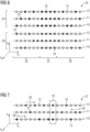
- FIG 7 schematically illustrates a corresponding randomised antiblurring sampling scheme 27.
- the different echo trains 14, 15, 16 are sampled in switching sampling directions 28 as indicated by corresponding arrows.
- the sampling direction 28 is switched after each of the echo trains.
- the described methods can be used to increase a reduction in total acquisition time that can be achieved with 2D compressed sensing by means of an increased data incoherence. This can in particular be achieved through a reduction in the number of echo trains. In this manner, even scenarios where SMS MRI is used and thus no reduction of the repetition time is feasible can benefit from a reduced total acquisition time.
- a combination of a randomised blipping scheme and a compressed sensing reconstruction is applied to SMS MRI.
- the described examples show how a method for accelerated 2D compressed sensing using SMS MRI can be realised.
Description
- The present invention refers to a method for 2D magnetic resonance imaging (MRI), and corresponding MRI device, computer program, and computer-readable storage medium.
- Even though magnetic resonance imaging - MR imaging, or MRI for short - is by now an established technique to create images of subjects such as patients, development of further improvements is still ongoing. One aim is to reduce acquisition time of MRI data to reduce stress for respective patients.
- One avenue for reducing the acquisition time lies in the relatively recently developed compressed sensing technique which refers to a group of methods for accelerated MR data acquisition based on pseudo- or semi-random, incomplete sampling of k-space. For slice-wise 2D MR-imaging the possibilities to create a random sampling are, however, very limited. In "Pseudo 2D Random Sampling for Compressed sensing MRI" by H. Wang, D. Liang, and L. Ying, published in Conference Proceedings Annual International Conference of the IEEE Engineering in Medicine and Biology Society, September 2009, DOI: 10.1109/IEMBS.2009.5334086 it is proposed to achieve the required incoherence by switching a phase-encoding direction by 90° during data acquisition. In practical applications, however, this method is difficult to implement, since typically the phase-encoding direction should be a direction of minimal body extent of a respective subject to reduce certain artefacts. Consequently, rotating the phase-encoding direction can in many cases lead to artefacts, such as flow artefacts, in resulting MR images which is obviously an undesirable result.
- Document
US 2016/341807 A1 is related to systems and methods for simultaneous multislice magnetic resonance imaging, in which a random blip gradient encoding scheme is utilized to impart a different phase to each of a plurality of different slice locations. During the application of each phase encoding gradient blip, a magnetic field gradient blip is also played out along the slice encoding direction - Document
2015/301145 A1 describes a method for producing images of a subject with a magnetic resonance imaging system. An excitation field in combination with a slice-select magnetic gradient field along a slice-select direction is provided. At least one readout magnetic field gradient is established along a frequency-encoding direction and at least one phase encoding magnetic field gradient along a phase-encoding direction. A sequence of phase shifts is imparted to the formed echo signals such that image data corresponding to an adjacent slice location is incoherently aliased across a field-of-view of a current slice location. Instead of using slice shifting to create coherent aliasing, the simultaneous slices may be encoded in a pseudo-random manner such that only incoherent slice-aliasing exists in the acquired data. - Document
US 2018/306880 A1 discloses systems and methods for simultaneous multi-slice imaging. An acquisition and reconstruction approach utilizing simultaneous excitation of 2-4 slices to maximize the data sampling time for each slice is described. - The publication M. Lustig et al.: "Compressive Chemical-shift-based Rapid Fat/Water Imaging", Proceedings of the International Society for Magnetic Resonance in Medicine, vol. 17, 2646, proposes to acquire phase-encodes randomly with varying density. To this end, echo-times are delayed randomly. A chemical-shift multi-dimensional image is reconstructed from undersampled data.
- It is an object of the present invention to enable a reduction in acquisition time in magnetic resonance imaging. This object is achieved by the subject matter of the independent claims. Advantageous embodiments with expedient developments of the present invention are indicated in the dependent claims as well as in the description and in the drawings.
- A method according to the present invention is defined in independent claim 1. The method is designed for 2D magnetic resonance imaging of a subject, such as a patient or a part of a patient. One step of this method comprises acquiring an undersampled k-space dataset for or of the respective subject using a simultaneous multi-slice technique (SMS MRI). Therein, to achieve an incoherent undersampling in at least one k-space direction - which as an example can be the kz-direction - an encoding for selecting the respective k-space points to be sampled for the k-space dataset is created. This is achieved by applying a blipped phase-encoding gradient in slice-direction in a pseudo-random manner and/or by pseudo-randomly imposing or impressing a phase on excitation-RF-pulses that are used in acquiring the k-space dataset, i.e. played out during the respective data- or imageacquisition. In any case, a pseudo-random phase variation is generated for or as the kz-encoding. In SMS MRI the acquisition of the k-space dataset can be seen as filling a multidimensional, in particular 3-dimensional, k-space or k-space matrix, wherein the imposing or impression of a phase by either of the above-mentioned means can be interpreted as a shift in the respective k-space direction or -dimension, e.g. in kz-direction. In another step of the method according to the present invention a compressed sensing (CS) reconstruction is performed based on the acquired undersampled k-space dataset to generate an MR image or a set of MR images of the respective subject.
- Typically, the compressed sensing reconstruction exploits a sparsity of a signal to recover it from fewer samples than required by the Nyquist sampling theorem. Typically, the compressed sensing reconstruction comprises an iterative optimisation process using non-linear Fourier transformation. Typically, the compressed sensing reconstruction comprises thresholding of intermediate reconstructed images. The basic idea here is that since it is known that traditional MR images can be compressed after reconstruction, it should be possible to only acquire a limited dataset in the first place that allows for a reconstruction of an MR image with an image quality that is at least comparable to that of a compressed traditional MR image. To accomplish this, typically an incoherent undersampling, a sparsifying transformation, and an iterative reconstruction process is required.
- Undersampling means that only a portion of the full k-space is measured, which allows for a significant reduction in data acquisition time. Preferably, undersampling means that the sampling rate is below the Nyquist sampling rate. Typically, the k-space is fully sampled if the Nyquist sampling theorem is meet. Typical partial data acquisition schemes such as for example, sampling or measuring only every second k-space point or k-space line are, however, inadvisable, since such a coherent, i.e. predictable sampling pattern typically creates unwanted ghost artefacts. In contrast, the undersampling for the present method is performed in an incoherent, i.e. pseudo- or semi-random, manner. This avoids the ghost artefacts and instead distributes a diffuse noise across the entire firstly reconstructed image. This noise can then be removed or reduced as part of the compressed sensing reconstruction.
- Sparsity refers to an extent or degree to which a matrix - in this case a k-space matrix partly filled with the acquired k-space dataset - is filled with meaningful or non-zero data. Even if the initial k-space matrix or k-space dataset is not sparse, this can typically be achieved by applying a sparsifying transform, for example based on wavelets.
- For the iterative reconstruction process, and initial image can be created from the original acquired k-space dataset. This initial image may contain the mentioned diffuse noise.
- Then, a sparsifying transform, such as wavelet decomposition, is applied to concentrate meaningful image characteristics into a reduced number of relatively high-intensity pixels. The diffuse noise can then be of lower intensity and distributed over many pixels, mostly in an image background. Next, a denoising step can be performed, for example by zeroing out pixels with values below a predetermined threshold, by digital filtering, and/or a subtraction.
- To a resulting sparsified dataset the inverse of the sparsifying transform and an inverse Fourier transform is applied to convert the denoised image-space data back into k-space data. The original k-space matrix or k-space dataset and the denoised k-space data can then be subtracted from each other to generate a difference k-space matrix or difference k-space dataset. The latter is then Fourier transformed into a corresponding difference image that is then compared to the initial image. The initial image and the difference image can then be added together to generate an updated or intermediate image.
- If a comparison between the initial image and the respective updated intermediate image shows a significant disparity or difference, for example a difference greater than a predetermined threshold, then another iteration is performed, starting with applying the sparsifying transform to the respective updated or intermediate image that is in this iteration then used instead of the initial image. If no significant disparity or difference is detected in the last step of one iteration, the respective updated or intermediate image is used as a final reconstructed MR image.
- Simultaneous multi-slice (SMS) MRI is a method or technique, wherein multiple slices of the respective subject are simultaneously excited or stimulated using a single RF pulse. This technique can in and of itself lead to a reduction of total acquisition time. There are, however, limitations in an achievable reduction of acquisition time, in particular for RARE (rapid acquisition with refocused echoes) techniques, such as TSE (turbo spin echo) imaging, which comprise a bulk of routinely performed measurements. For example, a possible reduction or variation of a repetition time TR can lead to variations in an image contrast when using TSE-imaging, which is unwanted in typical practical or clinical imaging applications.
- The presently proposed combination of an SMS imaging technique with a compressed sensing reconstruction advantageously enables a further reduction in acquisition time, in particular for 2D TSE-based MR-imaging without introducing the mentioned image contrast variations or ghost artefacts. This is mainly the case, because of the possibility of acquiring or sampling the k-space dataset with an increased incoherence, for example by at least pseudo-randomly reducing a number of echo trains. This means that even in scenarios where the repetition time TR cannot be reduced an effective reduction in total acquisition time can be achieved without a significant reduction of image quality.
- In terms of the present invention a blipped phase-encoding gradient can refer to an intermittent application of that gradient or gradient field. This means that there can be multiple times or instances where the blipped phase-encoding gradient is applied or turned on, i.e. active, and these times or instances are interrupted by times where the phase-encoding gradient is not applied, i.e. turned off or inactive. The blipped phase-encoding gradient can therefore also be regarded as a slow gradient as opposed to typical fast gradients that are basically continually applied with switching directions or polarities. While these fast gradients also move through points of zero intensity. These zero points are arbitrarily short, while the zero- or off-times between individual applications or activations, i.e. between individual blips of the slow blipped phase-encoding gradient are extended periods of time, each of which can be at least on the same time-scale as or even longer than an individual blip or activation time of the blipped phase-encoding gradient. The blipped phase-encoding gradient can advance a sampling position with each application, i.e. with each blip, for example in the ky-direction or along the ky-axis.
- According to the present invention, the blipped phase-encoding gradient is also varied in the slice- or slice-select-direction within each echo train so that different echoes in a specific echo train can sample k-space points from different coordinates in or along the at least one k-space direction, e.g. from different kzcoordinates. Therein, as a boundary condition for the incoherent undersampling it is ensured that the k-space centre is sampled at essentially the same relative time within all of the echo trains. By varying or pseudo-randomising the imposed or impressed phase for each echo train a greater incoherence can be achieved, advantageously aiding the compressed sensing reconstruction. On the other hand, varying or pseudo-randomising the imposed or impressed phase in each echo train so that the k-space centre is essentially sampled at the same relative time has the advantage of ensuring that a wanted predetermined image contrast is actually achieved, which can advantageously reduce artefacts or unwanted variations in the resulting MR images. As described above, the boundary condition can, for example, be applied as a predetermined factor or requirement for a function or algorithm that can be used to generate the incoherent sampling pattern for acquiring the k-space dataset.
- In an advantageous development of the present invention it is ensured that a sampling probability for k-space points in a central portion or central region of the k-space is higher than for k-space points in or closer to a k-space periphery as a boundary condition for the incoherent, i.e. pseudo-random undersampling. A corresponding pseudo-random sampling pattern can, in other words, be density-weighted with higher weights and therefore a higher density of sampling points at or near to the k-space centre compared to the k-space periphery. This is particularly advantageous, since the central region of k-space typically contains more essential or important information for the final MR image than the k-space periphery. Therefore, employing the incoherent undersampling while simultaneously ensuring that at or near the k-space centre more k-space points are measured then further towards the periphery can result in an optimal compromise between the desired randomness or incoherence and the quality or importance of the actually sampled or measured, i.e. acquired k-space dataset. Consequently, the proposed approach can lead to an optimal image quality of the resulting MR image while simultaneously reducing acquisition time compared to the state of the art. For a practical application, the boundary condition may for example be applied by including a predetermined density-function with predetermined weights in a function or algorithm for generating the pseudo-random sampling pattern.
- In a further advantageous development of the present invention the k-space dataset is acquired using a GRAPPA technique (GeneRalised Auto calibrating Partial Parallel Acquisition) for parallel imaging. Therein, the k-space data of the k-space points in the central portion or region of the k-space is used as reference data. The current parallel imaging techniques for accelerated imaging, such as GRAPPA, typically require a fully encoded reference dataset - for example to estimate a spatial coil sensitivity. In traditional approaches this reference data is acquired separately from the respective k-space data for the actual MR image using a separate sequence. This obviously requires additional acquisition time. The additional acquisition time for the reference data can be avoided using the presently proposed approach based on the insight that due to the higher sampling probability or higher sampling density in the central region of the k-space corresponding k-space data may be good enough, i.e. complete enough to use as the reference data for the GRAPPA technique. This can apply to slice-GRAPPA as well and to in-plain-GRAPPA reconstruction techniques. Consequently, a total measurement time or data acquisition time can be further reduced to advantageously decrease stress for the respective subject even more.
- In a further advantageous development of the present invention different numbers of sampled k-space points are allowed for different coordinates in or of the at least one k-space direction, e.g. for different kz-coordinates in the incoherent undersampling, i.e., in the incoherent acquisition of the k-space dataset. There is, in other words, no boundary condition requiring that for each slice, i.e. for every kz-coordinate a respective total number of sampling points must be the same. This can advantageously further increase the total incoherence or pseudo-randomness of the k-space dataset. This in turn can advantageously improve a performance of the compressed sensing reconstruction, ultimately resulting in an improved image quality of the final MR image.
- In an advantageous development of the present invention multiple different image contrasts are acquired and the undersampling is also incoherently performed in a corresponding additional sampling dimension that depends on the types of the different contrasts. Different image contrasts in this sense can, for example, be T1, T2, inversion recovery, proton-density (pd) and the like. Acquisition of such different image contrasts advantageously enables reconstruction of corresponding differently weighted MR images, which can show different details or yield different insights for improved diagnostics. The proposed method of a pseudo-randomised sampling scheme can be applied with particular advantage when acquiring multiple different image contrasts. This is the case, because when acquiring multiple image contrasts, a corresponding additional dimension is spanned and the incoherence can also be applied in this dimension which aids the compressed sensing reconstruction. Additionally, the additional dimension also means that a sparsity of the acquired k-space dataset is increased, which is also beneficial for the compressed sensing reconstruction. Examples for the different contrasts and the corresponding additional sampling dimension are given below.
- In a further advantageous development of the present invention the echo time is used as the additional sampling dimension so that echo times are at least pseudo-randomised across the acquisitions of the different image contrasts. In other words, a mapping-method, such as T2-mapping or multi-parameter-mapping can be used. Here, a respective time at which a central k-space echo is measured within a respective echo train can be varied to increase overall incoherence. This can advantageously result in reduced artefacts in the final MR image.
- In a further advantageous development of the present invention a Dixon technique, such as a 2-, 3-, or multipoint-Dixon imaging method, is used. The additional sampling dimension is spanned by a phase state of different signals so that differently pseudo-randomised sampling patterns are used for in-phase and out-of-phase echoes. Dixon techniques capitalise on chemical shift differences between different molecules such as fat and water and use the in-phase/out-of-phase cycling of these different molecules. For example, two sets of spin echoes can be acquired with slightly different echo times, a first with - for example - fat and water signals in phase at a centre of the echo and a second with the echo time varied or adjusted, for example by a few milliseconds so that fat and water signals are out of phase. An underlying idea here is that the corresponding in-phase and out-of-phase images can be combined so that for example fat-only and water-only MR images can be created. By using at least partially different sampling points or k-space points for the in-phase echoes and the out-of-phase or opposed phase echoes incoherence can be achieved in this additional dimension, thereby increasing the overall total incoherence, which again can benefit the compressed sensing reconstruction and result in an improved image quality of the final MR image.
- The different sampling patterns for the in-phase and the out-of-phase echoes can preferably be used or at least differ from each other in the k-space periphery. In a central region of the k-space, the sampling density might as described be increased to the point where essentially every k-space point in the central region is sampled, meaning that effectively the same complete sampling pattern can be used for both types of echoes in the central k-space region. Differing sampling patterns in the k-space periphery can, however, still be advantageous.
- Another aspect of the present invention is a magnetic resonance imaging device (MRI device), in accordance with
independent claim 8, comprising an imaging system for acquiring k-space data of or for a subject, and further comprising means for processing the acquired k-space data. The magnetic resonance imaging device according to the present invention is adapted to, in particular automatically or semi-automatically, execute or carry out at least one embodiment of the method according to the present invention. The imaging system can comprise essentially state-of-the-art components such as magnets, a signal generator, an amplifier, measurement or signal detection electronics, a data store, a processor connected therewith, and/or the like. - Another aspect of the present invention is a computer program in accordance with
claim 9 comprising instructions to cause the magnetic resonance imaging device according to the present invention to execute or carry out at least one embodiment of the method according to the present invention. The method according to the present invention can, in other words, essentially be a computerimplemented method in form of the computer program according to the present invention. This computer program can then be executed by a processor of the magnetic resonance imaging device or a computer or data processing device directly or indirectly connected to a magnetic resonance imaging device and/or comprising an interface over which the acquired undersampled k-space dataset is provided. The computer program according to the present invention may comprise additional instructions and/or parts, for example to interface with additional software and/or hardware modules, to capture user input, to provide a user interface (GUI), and/or the like. - Another aspect of the present invention is a computer-readable storage medium having stored thereon a computer program according to the present invention in at least one embodiment.
- The magnetic resonance imaging device according to the present invention may be adapted to execute the method according to the present invention by comprising or being provided with a computer-readable storage medium according to the present invention, which can in particular be connected to a processor of the magnetic resonance imaging device.
- The embodiments and developments of the present invention described herein for at least one aspect of the present invention, that is, at least for the method, the magnetic resonance imaging device, the computer program, and the computer-readable storage medium, as well as the corresponding advantages may be applied to any and all aspects of the present invention.
- Further advantages, features, and details of the present invention derive from the following description of preferred embodiments of the present invention as well as from the drawings pertaining to the present invention. The features and feature combinations previously mentioned in the description as well as the features and feature combinations mentioned in the following description of the figures and/or shown in the figures alone can be employed not only in the respectively indicated combination but also in other combinations or taken alone.
- In the drawings
- FIG 1
- schematically shows an exemplary flow chart for a magnetic resonance imaging method;
- FIG 2
- schematically shows a magnetic resonance imaging device for carrying out the method;
- FIG 3
- illustrates a state of the art SMS sampling scheme;
- FIG 4
- illustrates a randomised SMS sampling scheme;
- FIG 5
- illustrates an improved randomised SMS sampling scheme;
- FIG 6
- illustrates a randomised sampling scheme for the Dixon sampling technique; and
- FIG 7
- illustrates a randomised sampling scheme to reduce blurring effects.
- The examples described below refer to preferred embodiments of the present invention. Therein, individual components and process steps of the embodiments each constitute individual, independent features of the present invention that can further develop the invention independently of each other as well as in combinations not explicitly described. The described embodiments can be further developed or supplemented by features, components and/or steps already described above.
- In the figures features that are the same, functionally the same or correspond to each other are indicated by the same reference signs.
-
FIG 1 schematically shows an exemplary flow chart 1 for a magnetic resonance imaging method with process steps S1, S2, and S3. This method will be described with reference to the other figures and can, for example, be carried out using a magnetic resonance imaging device, such as theMRI device 2 schematically shown inFIG 2 . - The
MRI device 2 is presently used for imaging apatient 3. For this purpose, theMRI device 2 comprises animaging system 4 that is only hinted at schematically but can comprise multiple different magnets as well as a signal generator for generating RF-pulses to excite multiple slices of thepatient 3 at once. TheMRI device 2 further comprises adata processing device 5. Thedata processing device 5 itself comprises at least aprocessor 6, and connected thereto to amemory 7 on which a computer program is stored. This computer program implements at least some of the process steps S1, S2, and S3 indicated inFIG 1 . Correspondingly, these process steps can represent functions or modules of the computer program. - Additionally, a
monitor 8 is provided as part of theMRI device 2 or connected thereto. Themonitor 8 can be used to output MRI images generated by theMRI device 2 in general or by thedata processing device 5 specifically. - The presently described magnetic resonance imaging method aims at further reducing a total required acquisition time over the state of the art. Conventional 2D MRI imaging methods, such as TSE, up to now allow only for an undersampling in one phase-encoding direction which severely limits the possibilities for generating an incoherently undersampled k-space dataset. Combined with the typical requirement of constant repetition times to achieve the desired image contrast the possibilities for a reduction in acquisition time are very limited even when using an SMS technique.
- In process step S1 the acquisition of the k-space dataset is prepared. This can comprise automatically or manually selecting slices of the patient to be imaged, selecting an acquisition method or sequence to be used, and generating a pseudo-randomised sampling pattern.
- In process step S2 the k-space dataset is acquired using the pseudo-randomised sampling pattern with incoherent undersampling.
- In process step S3 a compressed sensing reconstruction is performed based on the acquired k-space dataset. If applicable, a GRAPPA reconstruction can be performed here as well using calibration k-space data from a densely or even completely sampled central k-space region 25 (see
FIG 6 ) as reference data, for example to estimate coil sensitivities of multiple coils that might have been used in process step S2 for parallel imaging. In process step S3 using the compressed sensing reconstruction a final MR image of thepatient 3 is generated. This final MR image can then be stored on thememory 7 and/or output to themonitor 8, and/or to another device or software over a corresponding interface. - As described above for successful execution of the compressed sensing reconstruction the k-space should be incoherently undersampled and the acquired k-space dataset should be transformable into a sparse representation, for example, using a wavelet-transform. While the latter is generally possible, the possibilities for incoherent undersampling can be dependent on a type of the used acquisition method or sequence. For example, it is generally easier to achieve an undersampling with sufficient incoherence for a multi-dimensional base dataset. Suitable examples include time resolved datasets such as GRASP-VIBE or CS Cardiac CINE, 3D-datasets like CS SPACE, and datasets with an additional encoded k-space dimension, such as CS SEMAC.
- With reference to
FIGs 3 to 7 additional details regarding the incoherent sampling or acquisition of the k-space dataset will now be described. -
FIG 3 schematically illustrates aconventional sampling scheme 9 for a blipped CAIPIRINHA method (controlled aliasing in parallel imaging results in higher acceleration). - CAIPIRINHA is a parallel imaging technique using a group of unique k-space sampling patterns to reduce pixel aliasing and overlap on reconstructed images. Therein, acquired points in k-space are shifted from one another by applying additional offsets to the phase-encoding gradient tables. SMS MRI with blipped CAIPIRINHA can be seen as filling a three-dimensional k-space, wherein an application or impression of a phase by means of a gradient in slice direction kz or an application or impression of a phase onto an RF-pulse can be interpreted as a shift in the kz-direction.
- In
FIG 3 as well as the following figures three sets of k-space points, namely afirst set 10, asecond set 11, and athird set 12 are shown. Not all of these k-space points 13 are actually measured or sampled. Rather, a partial but coherent regular sampling pattern is used, comprising afirst echo train 14 on thefirst set 10, asecond echo train 15 on thesecond set 11, and athird echo train 16 on thethird set 12. Each of the echo trains 14, 15, 16 comprises multiple regularly spaced k-space points 13. InFIG 3 the echo trains 14, 15, 16 show the same spacing, the same number of sampled k-space points 13 perecho train space points 13 for each slice or kzcoordinate, that is, for each of thesets - For the sake of clarity and readability only some of the k-
space points 13 and some of the sampled points are indicated. - Other than shown in
FIG 3 a pseudo-randomised incoherent sampling pattern can be used for the presently proposed magnetic resonance imaging method that can combine an incoherent undersampling with the described compressed sensing reconstruction for 2D SMS MRI. For example,FIG 4 illustrates a randomisedsampling scheme 17 with varying density, i.e. with randomised or pseudo-randomised spacing between the actually sampled k-space points 13 in each of the echo trains 14, 15, 16. The randomisedsampling scheme 17 advantageously introduces randomness or incoherence, which enables a successful execution of the compressed sensing reconstruction. At the same time, the random sampling scheme, 17 can be relatively easily implemented and executed. Since a respective applied, i.e. imposed or impressed, phase can be the same for each of the echo trains 14, 15, 16, this can, however, result in different weighting of the k-space centre 19 (seeFIG 5 ) within the different echo trains 14, 15, 16. Also, the (pseudo-)randomness of therandom sampling scheme 17 can be limited by the boundary condition that for each kz-coordinate the same total number of k-space points 13 is sampled or measured, since all of the echo trains 14, 15, 16 may have to comprise the same number of recorded echoes. -
FIG 5 schematically illustrates a double randomisedsampling scheme 18 that can be used to further improve the proposed method. Therein, a respective imposed or impressed phase within each of the echo trains 14, 15, 16 is varied so that the k-space centre 19 is sampled essentially at the same relative point in time within each of the echo trains 14, 15, 16. Also, the double randomisedsampling scheme 18 is not limited by the boundary condition that for each kz-coordinate the same number of k-space points 13 must be sampled, which advantageously further increases the overall incoherence and thus the performance of the compressed sensing reconstruction. Since the double randomisedsampling scheme 18 introduces a variation or randomness in terms of the kz-coordinate within each of the echo trains 14, 15, 16, each of thesets space points 13 for thesets - It can be particularly advantageous to combine an incoherent undersampling with an acquisition of multiple image contrasts. This can, for example, mean that a mapping-method, such as T2-mapping or multi-parameter-mapping as in the known MDME-sequence (multi-delay multi-echo), or a multipoint-Dixon-imaging method can be used. In these methods an additional dimension for the compressed sensing reconstruction is spanned, which can advantageously increase a sparsity of the k-space dataset. As an example,
FIG 6 schematically illustrates a randomisedDixon sampling scheme 20, wherein at least partially different ones of the k-space points 13 are sampled for in-phase echoes 21 than for out-of-phase echoes 22. It can clearly be seen that sampled in-phase points 23 are differently distributed than sampled out-of-phase points 24. Therefore, an additional randomness or incoherence is introduced in the additional phase state dimension. To improve clarity and readability only some of the sampled in-phase points 23 and only some of the sampled out-of-phase points 24 are indicated and both are shown homogeneously but can in practice be acquired through multiple echo trains similarly to the echo trains 14, 15, 16 indicated inFIGs 3-5 . - It is also clearly visible that the sampled points 23, 24 are not distributed completely randomly. Rather, a density-weighted distribution is used, meaning that a probabilitydistribution describing whether or not one of the k-
space points 13 is actually sampled prioritises or emphasises the central k-space region 25 over the k-space periphery 26. Correspondingly, k-space points 13 in the central k-space reached 25 may be fully or almost fully sampled. This advantageously also opens up the possibility to use k-space data from the central k-space region 25 as reference data for use in a GRAPPA technique. - As a further improvement, in particular to reduce blurring effects due to T2-decay when using a TSE imaging sequence, each
echo train FIG 7 schematically illustrates a corresponding randomisedantiblurring sampling scheme 27. Here, the different echo trains 14, 15, 16 are sampled in switchingsampling directions 28 as indicated by corresponding arrows. Thesampling direction 28 is switched after each of the echo trains. - While
different sampling directions 28 are used for the different echo trains 14, 15, 16, the k-space centre 19 is still sampled at the same time within each of the echo trains 14, 15, 16. - Since the described methods are used in SMS MRI, multiple slices of the
patient 3 are excited at the same time. This means that a definite mapping between a respective kzcoordinate - represented here as the threesets - Advantageously, the described methods can be used to increase a reduction in total acquisition time that can be achieved with 2D compressed sensing by means of an increased data incoherence. This can in particular be achieved through a reduction in the number of echo trains. In this manner, even scenarios where SMS MRI is used and thus no reduction of the repetition time is feasible can benefit from a reduced total acquisition time. For this purpose a combination of a randomised blipping scheme and a compressed sensing reconstruction is applied to SMS MRI. In summary, the described examples show how a method for accelerated 2D compressed sensing using SMS MRI can be realised.
Claims (10)
- Method (1) for 2D magnetic resonance imaging of a subject (3) comprising the steps of- acquiring an undersampled k-space dataset for the subject (3) using a simultaneous multi-slice technique, wherein- to achieve an incoherent undersampling scheme in at least one k-space direction (kz) an encoding for selecting the respective k-space points (13) to be sampled for the k-space dataset is created by applying a blipped phase-encoding gradient in slice-direction in a pseudo-random manner and/or by pseudo-randomly impressing a phase on RF pulses used in acquiring the k-space dataset, and- performing a compressed sensing reconstruction based on the acquired k-space dataset to generate an MR image of the subject (3),
wherein- the blipped phase-encoding gradient is also varied in the slice direction within each echo train (14, 15, 16) of the incoherent undersampling scheme so that different echoes in a specific echo train (14, 15, 16) of the incoherent undersampling scheme can sample k-space points (13) from different k-space coordinates (10, 11, 12) in the at least one k-space direction (kz), wherein as a boundary condition for the incoherent undersampling scheme it is ensured that the k-space centre (19) is sampled at essentially the same relative time within all of the echo trains (14, 15, 16). - Method (1) according to claim 1, characterised in that as a boundary condition for the incoherent undersampling scheme it is ensured that a sampling probability for k-space points (13) in a central portion (25) of the k-space is higher than for k-space points (13) in or closer to a k-space periphery (26).
- Method (1) according to claim 2, characterised in that the k-space dataset is acquired using a GRAPPA technique for parallel imaging, wherein the k-space data of the k-space points (13) in the central portion (25) of the k-space is used as reference data for the GRAPPA technique.
- Method (1) according to one of the preceding claims, characterised in that for the incoherent undersampling scheme different numbers of sampled k-space points (13) are allowed for different coordinates (10, 11, 12) in the at least one k-space direction (kz).
- Method (1) according to any of the preceding claims, characterised in that multiple different image contrasts are acquired and the incoherent undersampling scheme is also incoherently performed in a corresponding additional sampling dimension that depends on the types of the different contrasts.
- Method (1) according to claim 5, characterised in that the echo time is used as the additional sampling dimension so that echo times are at least pseudo-randomised across the acquisitions of the different image contrasts.
- Method (1) according to claim 5 or claim 6, characterised in that a Dixon technique is used and the additional sampling dimension is spanned by a phase state of different signals so that differently pseudo-randomised sampling patterns are used for in-phase echoes (21) and out-of-phase echoes (22).
- Magnetic resonance imaging device (2) comprising an imaging system (4) for acquiring k-space data of a subject (3), and means (5, 6) for processing the acquired k-space data, wherein the magnetic resonance imaging device (2) is adapted to execute a method (1) according to any of claims 1 to 7.
- Computer program (1) comprising instructions (S1, S2, S3) which, when executed on the magnetic resonance imaging device (2) of claim 8, cause said magnetic resonance imaging device to execute a method (1) according to any of claims 1 to 7.
- Computer-readable storage medium (7) having stored thereon a computer program (1) according to claim 9.
Priority Applications (2)
| Application Number | Priority Date | Filing Date | Title |
|---|---|---|---|
| EP19184389.5A EP3761052B1 (en) | 2019-07-04 | 2019-07-04 | Simultaneous multi-slice 2d magnetic resonance imaging with compressed sensing |
| US16/914,780 US11313934B2 (en) | 2019-07-04 | 2020-06-29 | Method for 2D magnetic resonance imaging, corresponding MRI device, computer program, and computer-readable storage medium |
Applications Claiming Priority (1)
| Application Number | Priority Date | Filing Date | Title |
|---|---|---|---|
| EP19184389.5A EP3761052B1 (en) | 2019-07-04 | 2019-07-04 | Simultaneous multi-slice 2d magnetic resonance imaging with compressed sensing |
Publications (2)
| Publication Number | Publication Date |
|---|---|
| EP3761052A1 EP3761052A1 (en) | 2021-01-06 |
| EP3761052B1 true EP3761052B1 (en) | 2023-02-22 |
Family
ID=67180633
Family Applications (1)
| Application Number | Title | Priority Date | Filing Date |
|---|---|---|---|
| EP19184389.5A Active EP3761052B1 (en) | 2019-07-04 | 2019-07-04 | Simultaneous multi-slice 2d magnetic resonance imaging with compressed sensing |
Country Status (2)
| Country | Link |
|---|---|
| US (1) | US11313934B2 (en) |
| EP (1) | EP3761052B1 (en) |
Family Cites Families (10)
| Publication number | Priority date | Publication date | Assignee | Title |
|---|---|---|---|---|
| US7659718B1 (en) * | 2008-07-31 | 2010-02-09 | The Board Of Trustees Of The Leland Stanford Junior University | Blip design for random sampling compressed sensing of flyback 3D-MRSI |
| US9069050B2 (en) * | 2012-04-12 | 2015-06-30 | Jeffrey Duerk | Varying blipped trajectory in MRI |
| US9392958B2 (en) * | 2012-05-30 | 2016-07-19 | Siemens Aktiengesellschaft | Method of attenuation correction of positron emission tomography data and combined positron emission tomography and magnetic resonance tomography system |
| US10436866B2 (en) * | 2014-01-31 | 2019-10-08 | The General Hospital Corporation | Simultaneous multislice MRI with random gradient encoding |
| US9841481B2 (en) * | 2014-04-16 | 2017-12-12 | The Board Of Trustees Of The Leland Stanford Junior University | Multislice acquisition with incoherent aliasing |
| WO2015190508A1 (en) * | 2014-06-12 | 2015-12-17 | 株式会社 日立メディコ | Magnetic resonance imaging device and method for creating water-fat separation image |
| EP3333584B1 (en) * | 2017-04-12 | 2022-05-25 | Siemens Healthcare GmbH | Optimisation of the simultaneous detection of mr data in multiple volume elements or slices |
| US10753994B2 (en) * | 2017-04-21 | 2020-08-25 | University Of Virginia Patent Foundation | Systems and methods for simultaneous multi-slice imaging |
| JP6956509B2 (en) * | 2017-04-21 | 2021-11-02 | キヤノンメディカルシステムズ株式会社 | Magnetic resonance imaging device |
| EP3413072A1 (en) | 2017-06-06 | 2018-12-12 | Siemens Healthcare GmbH | Method for simultaneous multi-slice magnetic resonance imaging |
-
2019
- 2019-07-04 EP EP19184389.5A patent/EP3761052B1/en active Active
-
2020
- 2020-06-29 US US16/914,780 patent/US11313934B2/en active Active
Also Published As
| Publication number | Publication date |
|---|---|
| EP3761052A1 (en) | 2021-01-06 |
| US11313934B2 (en) | 2022-04-26 |
| US20210003654A1 (en) | 2021-01-07 |
Similar Documents
| Publication | Publication Date | Title |
|---|---|---|
| CN106461746B (en) | Multi-echo MRI using repeated sampling of k-lines in a different sequence order per repeat | |
| Hansen et al. | Image reconstruction: an overview for clinicians | |
| EP2233940B1 (en) | Simultaneous excitation and acquisition in magnetic resonance | |
| US8155389B2 (en) | Method and system for motion correction in imaging systems | |
| EP1506420B1 (en) | Magnetic resonance imaging method with accelerated data acquisition | |
| US10901061B2 (en) | Accelerated diffusion-weighted magnetic resonance imaging with self-navigated, phase corrected tilted kernel reconstruction of phase encoded and point spread function encoded k-space | |
| WO2015036340A1 (en) | Metal resistant mr imaging | |
| JP2023109791A (en) | Parallel multi-slice MR imaging | |
| US9535148B2 (en) | Dynamic contrast enhanced magnetic resonance imaging with high spatial-temporal resolution | |
| JP5882469B2 (en) | Method and system for high speed MRI acquisition (RATE) using tailored signal excitation module | |
| WO2018114554A1 (en) | Dixon-type water/fat separation mr imaging | |
| JP7023954B2 (en) | Propeller MR imaging | |
| EP3761052B1 (en) | Simultaneous multi-slice 2d magnetic resonance imaging with compressed sensing | |
| US20230341493A1 (en) | Magnetic resonance imaging with prior knowledge and oversampling | |
| Kabasawa et al. | Pulse sequences and reconstruction in Fast MR imaging of the liver | |
| EP3185029A1 (en) | Mr imaging using propeller acquisition with t2 decay correction | |
| EP3432019A1 (en) | Parallel multi-slice mr imaging using signal averaging | |
| US20210270918A1 (en) | Method for generating a magnetic resonance image | |
| She et al. | Simultaneous image reconstruction and sensitivity estimation in parallel MRI using blind compressed sensing | |
| Mayer et al. | Metabolic Imaging with Dynamic Hyperpolarized NMR | |
| CN116953582A (en) | Multiple coil sensitivity maps and SENSE reconstruction for a magnetic resonance imaging apparatus | |
| Chang et al. | A kernel approach to compressed sensing parallel MRI | |
| Sumpf | Model-based T2 Relaxometry using Undersampled Magnetic Resonance Imaging | |
| WO2016188974A1 (en) | Mri using sense with acquisition of undersampled reference data via an ultrashort echo time sequence |
Legal Events
| Date | Code | Title | Description |
|---|---|---|---|
| PUAI | Public reference made under article 153(3) epc to a published international application that has entered the european phase |
Free format text: ORIGINAL CODE: 0009012 |
|
| STAA | Information on the status of an ep patent application or granted ep patent |
Free format text: STATUS: THE APPLICATION HAS BEEN PUBLISHED |
|
| AK | Designated contracting states |
Kind code of ref document: A1 Designated state(s): AL AT BE BG CH CY CZ DE DK EE ES FI FR GB GR HR HU IE IS IT LI LT LU LV MC MK MT NL NO PL PT RO RS SE SI SK SM TR |
|
| AX | Request for extension of the european patent |
Extension state: BA ME |
|
| STAA | Information on the status of an ep patent application or granted ep patent |
Free format text: STATUS: REQUEST FOR EXAMINATION WAS MADE |
|
| 17P | Request for examination filed |
Effective date: 20210119 |
|
| RBV | Designated contracting states (corrected) |
Designated state(s): AL AT BE BG CH CY CZ DE DK EE ES FI FR GB GR HR HU IE IS IT LI LT LU LV MC MK MT NL NO PL PT RO RS SE SI SK SM TR |
|
| RIC1 | Information provided on ipc code assigned before grant |
Ipc: G01R 33/48 20060101ALN20220830BHEP Ipc: G01R 33/561 20060101ALI20220830BHEP Ipc: G01R 33/483 20060101AFI20220830BHEP |
|
| GRAP | Despatch of communication of intention to grant a patent |
Free format text: ORIGINAL CODE: EPIDOSNIGR1 |
|
| STAA | Information on the status of an ep patent application or granted ep patent |
Free format text: STATUS: GRANT OF PATENT IS INTENDED |
|
| RIC1 | Information provided on ipc code assigned before grant |
Ipc: G01R 33/48 20060101ALN20220920BHEP Ipc: G01R 33/561 20060101ALI20220920BHEP Ipc: G01R 33/483 20060101AFI20220920BHEP |
|
| INTG | Intention to grant announced |
Effective date: 20221010 |
|
| GRAS | Grant fee paid |
Free format text: ORIGINAL CODE: EPIDOSNIGR3 |
|
| GRAA | (expected) grant |
Free format text: ORIGINAL CODE: 0009210 |
|
| STAA | Information on the status of an ep patent application or granted ep patent |
Free format text: STATUS: THE PATENT HAS BEEN GRANTED |
|
| AK | Designated contracting states |
Kind code of ref document: B1 Designated state(s): AL AT BE BG CH CY CZ DE DK EE ES FI FR GB GR HR HU IE IS IT LI LT LU LV MC MK MT NL NO PL PT RO RS SE SI SK SM TR |
|
| REG | Reference to a national code |
Ref country code: GB Ref legal event code: FG4D |
|
| REG | Reference to a national code |
Ref country code: CH Ref legal event code: EP |
|
| REG | Reference to a national code |
Ref country code: DE Ref legal event code: R096 Ref document number: 602019025449 Country of ref document: DE |
|
| REG | Reference to a national code |
Ref country code: AT Ref legal event code: REF Ref document number: 1549874 Country of ref document: AT Kind code of ref document: T Effective date: 20230315 Ref country code: IE Ref legal event code: FG4D |
|
| REG | Reference to a national code |
Ref country code: LT Ref legal event code: MG9D |
|
| REG | Reference to a national code |
Ref country code: NL Ref legal event code: MP Effective date: 20230222 |
|
| REG | Reference to a national code |
Ref country code: AT Ref legal event code: MK05 Ref document number: 1549874 Country of ref document: AT Kind code of ref document: T Effective date: 20230222 |
|
| PG25 | Lapsed in a contracting state [announced via postgrant information from national office to epo] |
Ref country code: RS Free format text: LAPSE BECAUSE OF FAILURE TO SUBMIT A TRANSLATION OF THE DESCRIPTION OR TO PAY THE FEE WITHIN THE PRESCRIBED TIME-LIMIT Effective date: 20230222 Ref country code: PT Free format text: LAPSE BECAUSE OF FAILURE TO SUBMIT A TRANSLATION OF THE DESCRIPTION OR TO PAY THE FEE WITHIN THE PRESCRIBED TIME-LIMIT Effective date: 20230622 Ref country code: NO Free format text: LAPSE BECAUSE OF FAILURE TO SUBMIT A TRANSLATION OF THE DESCRIPTION OR TO PAY THE FEE WITHIN THE PRESCRIBED TIME-LIMIT Effective date: 20230522 Ref country code: NL Free format text: LAPSE BECAUSE OF FAILURE TO SUBMIT A TRANSLATION OF THE DESCRIPTION OR TO PAY THE FEE WITHIN THE PRESCRIBED TIME-LIMIT Effective date: 20230222 Ref country code: LV Free format text: LAPSE BECAUSE OF FAILURE TO SUBMIT A TRANSLATION OF THE DESCRIPTION OR TO PAY THE FEE WITHIN THE PRESCRIBED TIME-LIMIT Effective date: 20230222 Ref country code: LT Free format text: LAPSE BECAUSE OF FAILURE TO SUBMIT A TRANSLATION OF THE DESCRIPTION OR TO PAY THE FEE WITHIN THE PRESCRIBED TIME-LIMIT Effective date: 20230222 Ref country code: HR Free format text: LAPSE BECAUSE OF FAILURE TO SUBMIT A TRANSLATION OF THE DESCRIPTION OR TO PAY THE FEE WITHIN THE PRESCRIBED TIME-LIMIT Effective date: 20230222 Ref country code: ES Free format text: LAPSE BECAUSE OF FAILURE TO SUBMIT A TRANSLATION OF THE DESCRIPTION OR TO PAY THE FEE WITHIN THE PRESCRIBED TIME-LIMIT Effective date: 20230222 Ref country code: AT Free format text: LAPSE BECAUSE OF FAILURE TO SUBMIT A TRANSLATION OF THE DESCRIPTION OR TO PAY THE FEE WITHIN THE PRESCRIBED TIME-LIMIT Effective date: 20230222 |
|
| PG25 | Lapsed in a contracting state [announced via postgrant information from national office to epo] |
Ref country code: SE Free format text: LAPSE BECAUSE OF FAILURE TO SUBMIT A TRANSLATION OF THE DESCRIPTION OR TO PAY THE FEE WITHIN THE PRESCRIBED TIME-LIMIT Effective date: 20230222 Ref country code: PL Free format text: LAPSE BECAUSE OF FAILURE TO SUBMIT A TRANSLATION OF THE DESCRIPTION OR TO PAY THE FEE WITHIN THE PRESCRIBED TIME-LIMIT Effective date: 20230222 Ref country code: IS Free format text: LAPSE BECAUSE OF FAILURE TO SUBMIT A TRANSLATION OF THE DESCRIPTION OR TO PAY THE FEE WITHIN THE PRESCRIBED TIME-LIMIT Effective date: 20230622 Ref country code: GR Free format text: LAPSE BECAUSE OF FAILURE TO SUBMIT A TRANSLATION OF THE DESCRIPTION OR TO PAY THE FEE WITHIN THE PRESCRIBED TIME-LIMIT Effective date: 20230523 Ref country code: FI Free format text: LAPSE BECAUSE OF FAILURE TO SUBMIT A TRANSLATION OF THE DESCRIPTION OR TO PAY THE FEE WITHIN THE PRESCRIBED TIME-LIMIT Effective date: 20230222 |
|
| PG25 | Lapsed in a contracting state [announced via postgrant information from national office to epo] |
Ref country code: SM Free format text: LAPSE BECAUSE OF FAILURE TO SUBMIT A TRANSLATION OF THE DESCRIPTION OR TO PAY THE FEE WITHIN THE PRESCRIBED TIME-LIMIT Effective date: 20230222 Ref country code: RO Free format text: LAPSE BECAUSE OF FAILURE TO SUBMIT A TRANSLATION OF THE DESCRIPTION OR TO PAY THE FEE WITHIN THE PRESCRIBED TIME-LIMIT Effective date: 20230222 Ref country code: EE Free format text: LAPSE BECAUSE OF FAILURE TO SUBMIT A TRANSLATION OF THE DESCRIPTION OR TO PAY THE FEE WITHIN THE PRESCRIBED TIME-LIMIT Effective date: 20230222 Ref country code: DK Free format text: LAPSE BECAUSE OF FAILURE TO SUBMIT A TRANSLATION OF THE DESCRIPTION OR TO PAY THE FEE WITHIN THE PRESCRIBED TIME-LIMIT Effective date: 20230222 Ref country code: CZ Free format text: LAPSE BECAUSE OF FAILURE TO SUBMIT A TRANSLATION OF THE DESCRIPTION OR TO PAY THE FEE WITHIN THE PRESCRIBED TIME-LIMIT Effective date: 20230222 |
|
| PGFP | Annual fee paid to national office [announced via postgrant information from national office to epo] |
Ref country code: GB Payment date: 20230807 Year of fee payment: 5 |
|
| REG | Reference to a national code |
Ref country code: DE Ref legal event code: R097 Ref document number: 602019025449 Country of ref document: DE |
|
| PG25 | Lapsed in a contracting state [announced via postgrant information from national office to epo] |
Ref country code: SK Free format text: LAPSE BECAUSE OF FAILURE TO SUBMIT A TRANSLATION OF THE DESCRIPTION OR TO PAY THE FEE WITHIN THE PRESCRIBED TIME-LIMIT Effective date: 20230222 |
|
| PGFP | Annual fee paid to national office [announced via postgrant information from national office to epo] |
Ref country code: FR Payment date: 20230720 Year of fee payment: 5 Ref country code: DE Payment date: 20230918 Year of fee payment: 5 |
|
| PLBE | No opposition filed within time limit |
Free format text: ORIGINAL CODE: 0009261 |
|
| STAA | Information on the status of an ep patent application or granted ep patent |
Free format text: STATUS: NO OPPOSITION FILED WITHIN TIME LIMIT |
|
| 26N | No opposition filed |
Effective date: 20231123 |
|
| PG25 | Lapsed in a contracting state [announced via postgrant information from national office to epo] |
Ref country code: SI Free format text: LAPSE BECAUSE OF FAILURE TO SUBMIT A TRANSLATION OF THE DESCRIPTION OR TO PAY THE FEE WITHIN THE PRESCRIBED TIME-LIMIT Effective date: 20230222 |
|
| PG25 | Lapsed in a contracting state [announced via postgrant information from national office to epo] |
Ref country code: MC Free format text: LAPSE BECAUSE OF FAILURE TO SUBMIT A TRANSLATION OF THE DESCRIPTION OR TO PAY THE FEE WITHIN THE PRESCRIBED TIME-LIMIT Effective date: 20230222 |
|
| REG | Reference to a national code |
Ref country code: DE Ref legal event code: R081 Ref document number: 602019025449 Country of ref document: DE Owner name: SIEMENS HEALTHINEERS AG, DE Free format text: FORMER OWNER: SIEMENS HEALTHCARE GMBH, MUENCHEN, DE |
|
| PG25 | Lapsed in a contracting state [announced via postgrant information from national office to epo] |
Ref country code: MC Free format text: LAPSE BECAUSE OF FAILURE TO SUBMIT A TRANSLATION OF THE DESCRIPTION OR TO PAY THE FEE WITHIN THE PRESCRIBED TIME-LIMIT Effective date: 20230222 |
|
| REG | Reference to a national code |
Ref country code: CH Ref legal event code: PL |
|
| PG25 | Lapsed in a contracting state [announced via postgrant information from national office to epo] |
Ref country code: LU Free format text: LAPSE BECAUSE OF NON-PAYMENT OF DUE FEES Effective date: 20230704 |
|
| PG25 | Lapsed in a contracting state [announced via postgrant information from national office to epo] |
Ref country code: LU Free format text: LAPSE BECAUSE OF NON-PAYMENT OF DUE FEES Effective date: 20230704 |