EP3760985B1 - Elektrooptischer flüssigkeitssensor - Google Patents
Elektrooptischer flüssigkeitssensor Download PDFInfo
- Publication number
- EP3760985B1 EP3760985B1 EP20183566.7A EP20183566A EP3760985B1 EP 3760985 B1 EP3760985 B1 EP 3760985B1 EP 20183566 A EP20183566 A EP 20183566A EP 3760985 B1 EP3760985 B1 EP 3760985B1
- Authority
- EP
- European Patent Office
- Prior art keywords
- light
- liquid
- amount
- sensor
- electro
- Prior art date
- Legal status (The legal status is an assumption and is not a legal conclusion. Google has not performed a legal analysis and makes no representation as to the accuracy of the status listed.)
- Active
Links
Images







Classifications
-
- G—PHYSICS
- G01—MEASURING; TESTING
- G01F—MEASURING VOLUME, VOLUME FLOW, MASS FLOW OR LIQUID LEVEL; METERING BY VOLUME
- G01F23/00—Indicating or measuring liquid level or level of fluent solid material, e.g. indicating in terms of volume or indicating by means of an alarm
- G01F23/22—Indicating or measuring liquid level or level of fluent solid material, e.g. indicating in terms of volume or indicating by means of an alarm by measuring physical variables, other than linear dimensions, pressure or weight, dependent on the level to be measured, e.g. by difference of heat transfer of steam or water
- G01F23/28—Indicating or measuring liquid level or level of fluent solid material, e.g. indicating in terms of volume or indicating by means of an alarm by measuring physical variables, other than linear dimensions, pressure or weight, dependent on the level to be measured, e.g. by difference of heat transfer of steam or water by measuring the variations of parameters of electromagnetic or acoustic waves applied directly to the liquid or fluent solid material
- G01F23/284—Electromagnetic waves
- G01F23/292—Light, e.g. infrared or ultraviolet
-
- G—PHYSICS
- G01—MEASURING; TESTING
- G01D—MEASURING NOT SPECIALLY ADAPTED FOR A SPECIFIC VARIABLE; ARRANGEMENTS FOR MEASURING TWO OR MORE VARIABLES NOT COVERED IN A SINGLE OTHER SUBCLASS; TARIFF METERING APPARATUS; MEASURING OR TESTING NOT OTHERWISE PROVIDED FOR
- G01D11/00—Component parts of measuring arrangements not specially adapted for a specific variable
- G01D11/24—Housings ; Casings for instruments
- G01D11/26—Windows; Cover glasses; Sealings therefor
-
- G—PHYSICS
- G01—MEASURING; TESTING
- G01F—MEASURING VOLUME, VOLUME FLOW, MASS FLOW OR LIQUID LEVEL; METERING BY VOLUME
- G01F23/00—Indicating or measuring liquid level or level of fluent solid material, e.g. indicating in terms of volume or indicating by means of an alarm
- G01F23/22—Indicating or measuring liquid level or level of fluent solid material, e.g. indicating in terms of volume or indicating by means of an alarm by measuring physical variables, other than linear dimensions, pressure or weight, dependent on the level to be measured, e.g. by difference of heat transfer of steam or water
- G01F23/28—Indicating or measuring liquid level or level of fluent solid material, e.g. indicating in terms of volume or indicating by means of an alarm by measuring physical variables, other than linear dimensions, pressure or weight, dependent on the level to be measured, e.g. by difference of heat transfer of steam or water by measuring the variations of parameters of electromagnetic or acoustic waves applied directly to the liquid or fluent solid material
- G01F23/284—Electromagnetic waves
- G01F23/292—Light, e.g. infrared or ultraviolet
- G01F23/2921—Light, e.g. infrared or ultraviolet for discrete levels
- G01F23/2922—Light, e.g. infrared or ultraviolet for discrete levels with light-conducting sensing elements, e.g. prisms
Definitions
- the present invention relates generally to liquid sensors, and in particular to a method of operating an electro-optic liquid sensor.
- sensors have been developed for detecting the presence of fluid.
- One sensor type is an electro-optic sensor including a light source, a prism, and a light detector.
- light emitted from the light source may be returned to the light detector by the prism only if no liquid is present. If liquid is present, no light or limited light may be returned to the light detector.
- EP3318849A1 relates to a method for operating an electro-optic liquid sensor, involving determining whether liquid is present in a liquid chamber, based on a first and a second amount of light, in which a first sensitivity level is different from a second sensitivity level.
- the present invention is a method of operating an electro-optic sensor which comprises disposing at least a portion of the electro-optic sensor in a liquid chamber; testing, via a timer, for a timeout occurrence associated with the timer, the timer including a timing circuit; if there is a timeout occurrence, then indicating that the electro-optic sensor (16) is not functioning; if there is no timeout occurrence associated with the timer, then providing light from a light source of the electro-optic sensor at a first intensity; driving a light detector of the electro-optic sensor at a first sensitivity level; receiving, via the light detector, a first amount of light from the light source; determining whether liquid is present in the liquid chamber according to the first amount of light, providing light from the light source at a second intensity; driving the light detector at a second sensitivity level; receiving, via the light detector, a second amount of light from the light source; and confirming whether liquid is present in the liquid chamber according to the second amount of light.
- the first sensitivity level is different from the second sensitivity level.
- the electro-optic sensor includes a prism and a reflective optical member.
- the reflective optical member is arranged to reflect light emitted by the light source to the light detector when a liquid is disposed between the light source and the reflective optical member.
- the electro-optic sensor includes a photo diode-based sensor, the light source includes an LED, and the timing circuit is configured to cap an amount of energy through a circuit of the electro-optic sensor. Determining whether liquid is present in the liquid chamber according to the first amount of light may include comparing the first amount of light to a threshold value, and determining that liquid is not present if the first amount of light is greater than the threshold value.
- the second intensity may be greater than the first intensity and the second sensitivity level may be more sensitive than the first sensitivity level.
- Confirming whether liquid is present in the liquid chamber may include confirming that liquid is present if the second amount of light is greater than a second threshold value and determining an error has occurred if the second amount of light is not greater than the second threshold value.
- the second intensity may be less than the first intensity and the second sensitivity level may be less sensitive than the first sensitivity level (e.g., effectively a third intensity and a third sensitivity).
- Confirming whether liquid is present in the liquid chamber may include confirming that liquid is not present if the second amount of light is less than a third threshold value and determining an error has occurred if the second amount of light is not less than the third threshold value.
- the light detector may include an optical head assembly disposed in the liquid chamber and an electronic module assembly disposed outside of the liquid chamber.
- the optical head assembly may be connected to the electronic module assembly via one or more fiber optic cables.
- At least one fiber optic cable of the one or more fiber optic cables may be connected to a wall of the liquid chamber via a hermetically sealed fitting.
- the one or more fiber optic cables may include a single fiber.
- the method may include disposing all active components of the electro-optic sensor outside of the liquid chamber.
- a method of operating an electro-optic sensor may include providing a liquid chamber; providing the electro-optic sensor including a light source and a light detector that may include a photodiode-based transimpedance amplifier; conducting a first test of the electro-optic sensor without liquid in the liquid chamber and with the light source off; conducting a second test of the electro-optic sensor without liquid in the liquid chamber and with the light source on; conducting a third test of the electro-optic sensor with liquid in the liquid chamber and with the light source off; conducting a fourth test of the electro-optic sensor with liquid in the liquid chamber and with the light source on; setting a threshold value for the electro-optic sensor according to results of the fourth test; and/or operating the electro-optic sensor in a normal operating mode, including determining that liquid is present in the liquid chamber if at least one of an intensity and an amount of light received by the light detector is less than the threshold value.
- An electro-optic sensor may include a first connector connected to the second end of the first section of the fiber optic cable, and a second connector connected to the first end of the second section of the fiber optic cable. The first connector and the second connector may be configured to be connected together.
- An electro-optic sensor may include a third connector connected to the second end of the second section of the fiber optic cable.
- the electronic module assembly may include a connector configured to be connected with the third connector. At least one of the first section and the second section may include a single fiber.
- An electro-optic sensor may include a light source configured to be driven at a plurality of intensities. The optical head assembly may be configured to receive light from the light source.
- Liquid sensors that may be used in the claimed method may improve on other electro-optic liquid sensors by providing capability for assessing the operational state of the sensor in the presence of liquid.
- some electro-optic sensors are generally only capable of being tested while not in liquid. Accordingly, electro-optic sensors that may be used in the claimed method may enable improved testing and functionality over other electro-optic liquid sensors.
- FIG. 1 is a block diagram view of a system 10 including a component 12 for which determining the presence of liquid may be desirable.
- the component 12 may include a liquid chamber 14, and the system 10 may include a liquid sensor 16 and/or an electronic control unit (ECU) 18.
- ECU electronice control unit
- the component 12 may be any component in any field that includes or may be exposed to liquid in its operation.
- the component 12 may be or may be included in a mechanical, electrical, hydraulic, pneumatic, and/or other known actuator or actuation system.
- the component 12 may include a liquid chamber 14 configured to store and/or receive a liquid.
- the liquid may be, for example only, of a type necessary for the functionality of the component 12 (e.g., hydraulic fluid, liquid for lubrication, fuel, etc.), liquid incidental to the environment of the component 12, and/or liquid that is detrimental to the function of the component 12.
- the liquid sensor 16 may be coupled with the component 12.
- the liquid sensor 16 may be disposed at least partially within the liquid chamber 14 of the component 12.
- the liquid sensor 16 is an electro-optic sensor, such as that described in conjunction with FIGS. 2-4 and/or FIGS. 8 and 9 .
- an ECU 18 may be electrically coupled to the sensor 16 and may be configured to drive the sensor 16, receive feedback from the sensor 16, assess whether liquid is present or absent in the liquid chamber 14, and/or assess the operational state of the sensor 16.
- An ECU 18 may comprise, one or more of a processor, a non-volatile computer-readable memory, an application-specific integrated circuit (ASIC), field-programmable gate array (FPGA), and/or other known processing or memory devices.
- the ECU 18 may be or may comprise a dedicated processing resource for the sensor 16, or may be or may comprise processing resources for numerous sensors, components, and/or systems.
- the ECU 18 may be electrically coupled to the sensor 16 through known wired and/or wireless connections.
- the ECU 18 may be configured to perform various functions, including those described in greater detail herein, with appropriate programming instructions and/or code embodied in software, hardware, and/or other media.
- the ECU 18 may include a plurality of controllers.
- the ECU 18 may include and/or be connected to an input/output (I/O) interface and/or a display.
- I/O input/output
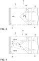
- FIG. 2 is a diagrammatic view of an example of the electro-optic liquid sensor 16 that may be used in the claimed method.
- the sensor 16 includes a light source 20, a light detector 22, a prism 24, and a reflective optical member 26 (which may also be referred to as an optical shield), which may be generally disposed within a housing 28.
- the housing 28 may include one or more liquid ports 30 for permitting liquid to flow into and out of a chamber 32 of the housing 28.
- the chamber 32 may define a gap between the prism 24 and the optical member 26 of a size d.
- d may be about 2,54 cm (an inch) or less. Of course, other dimensions may be employed as appropriate for particular applications.
- the light source 20 may be configured to emit light of one or more chosen frequencies and powers/intensities appropriate for a given application (e.g., appropriate for the characteristics of the other elements of the sensor 16, such as shape, orientation, materials, reflectivity, etc., and/or according to characteristics of the liquid to be detected, such as density, scattering properties, etc.).
- a light frequency should be understood to include either or both of a specific frequency of light and a frequency band.
- the light source 20 may be configured to emit light in the infrared portion and/or the near-infrared portion of the electromagnetic spectrum.
- the light source 20 includes light-emitting diode (LED), or, according to examples not encompassed by the wording of the claims, a laser, or other known light source.
- the light detector 22 may be configured to detect light of one or more frequencies of light, including at least the frequency of light emitted by the light source 20.
- the light detector 22 includes a photo diode-based sensor, or, according to examples not encompassed by the wording of the claims, one or more of a phototransistor, photodiode, and/or other light detecting device.
- the prism 24 may include a member, article, and/or device comprising one or more components that may be configured in size, shape, and/or materials to reflect light/a light signal from the light source 20 to the light detector 22 in certain conditions and to pass light from the light source 20 through the prism 24 in certain conditions.
- the prism 24 may be configured to reflect light from the light source 20 to the light detector 22 when liquid is not present around the prism 24, and to pass light from the light source through the prism 24 when liquid is present around and/or near the prism 24 (e.g., in chamber 32).
- the prism 24 may comprise borosilicate glass, fused silica (quartz), one or more polymers, etc., that is optically transmissive at least to light of the frequency or frequencies emitted by the light source 20.
- the prism 24 may be optically-transmissive to light in the infrared and/or near-infrared portions of the electromagnetic spectrum, for example only.
- the reflective optical member 26 is arranged and configured to reflect light emitted by the light source 20 to the light detector 22, in certain conditions.
- the optical member 26 may have a degree of reflectivity for one or more frequencies of light that may be tailored for a particular application.
- the optical member 26 may have complete or near-complete reflectivity for the frequency or frequencies of light emitted by the light source 20.
- the optical member 26 may have less-than-complete reflectivity for the frequency or frequencies of light emitted by the light source 20.
- the reflective optical member 26 may be disposed on/at a side of the housing 28 opposite the light source 20 and the light detector 22.
- the light source 20 may emit light in the direction of the optical member 26.
- the prism 24 may be disposed at least partially between the light source 20 and the optical member 26 and at least partially between the light detector 22 and the optical member 26. Accordingly, in the example generally illustrated in FIG. 2 , light may travel from the light source 20, through the prism 24, through the chamber 32, to the optical member 26, and may be reflected by the optical member 26 back through the chamber 32 and prism 24 to the light detector 22, in certain conditions.
- the distance d between the optical member 26 and the prism 24 may be tailored to the geometric relationship between the optical member 26, prism 24, light detector 22, and light source 20 for the optical member 26 to effectively reflect light emitted by the light source 20 to be returned to the light detector 22.
- the electro-optic liquid sensor 16 may be configured to detect the presence of liquid by returning a different amount of light from the light source 20 to the light detector 22 when liquid is present in the chamber 32 than when liquid is not present in the chamber 32.
- the prism 24 may return a first amount of light from the light source 20 to the light detector 22.
- the prism 24 may return substantially all light emitted by the light source 20 to the light detector 22 when no liquid is present.
- the prism 24 when the chamber 32 is filled with liquid, the prism 24 may return very little of or none of the light from the light source 20 to the light detector 22.
- the prism 24 may pass some portion of the light emitted by the light source 20, some of which light may disperse in the liquid, and some of which light may propagate to the optical member 26, be reflected by the optical member 26 to the light detector 22, and be received by the light detector 22. Accordingly, a relatively higher amount of light received by the light detector 22 may be associated with the absence of liquid from the chamber 32, and a relatively smaller amount of light received by the light detector 22 may be associated with the presence of liquid in the chamber 32.
- Examples that may be used in the claimed method of an electro-optic liquid sensor 16 may improve on other electro-optic sensors by enabling the sensor 16 to be tested in the presence of liquid.
- Other electro-optic sensors generally do not provide any means by which a light signal may be returned to the light detector in the presence of liquid. As a result, a faulty sensor may be indistinguishable from the presence of liquid in known sensors.
- the electro-optic sensor 16 may return a light signal to the light detector 22 in the presence of liquid, a faulty sensor (which may always indicate zero light received by the light detector 22) may be distinguished from the presence of fluid (which may indicate a nonzero amount of light received by the light detector, but less light received by the light detector 22 than when liquid is absent).
- an ECU 18 may be configured to operate the electro-optic sensor 16 to determine whether liquid is present in the chamber 32 and to determine whether the sensor 16 is or is not operating properly (e.g., assess the operational state of the sensor 16). Accordingly, in an embodiment, the ECU 18 may be configured to operate the sensor 16 in a liquid detection mode and a test mode. The liquid detection mode and the test mode may be implemented separately by the ECU, or may be implemented together.
- FIG. 5 is a flow chart generally illustrating a method 40 of operating an electro-optic sensor 16 not according to the claimed invention, but useful to understand it.
- One or more steps of the method 40 may be performed by the ECU 18 shown in FIG. 1 to operate the sensor 16 of FIG. 2 .
- the method 40 may include steps for implementing a liquid detection mode and a test mode of the electro-optic sensor 16 together.
- the method 40 may begin with a first driving step 42 that includes driving (e.g., providing light from) the light source 20 at a first frequency and intensity.
- the frequency and intensity may be selected according to the characteristics of the components of the sensor 16 and/or according to the liquid to be detected.
- the method 40 may continue to a first receiving step 44 that may include receiving reflected light with the light detector 22.
- the received light may be of the same frequency as that emitted by the light source 20 in the first driving step 42.
- a first comparison step 46 the amount or intensity or light received, R1, may be compared to a first threshold, T1.
- the method 40 may continue to a second driving step 48 that includes driving the light source 20 at a second frequency and intensity.
- the second frequency may be the same as the first frequency, in an embodiment.
- the second intensity may be the same as the first intensity.
- the second frequency and/or intensity may be different from the first frequency and/or intensity.
- the second intensity may be greater than the first intensity.
- a higher intensity may be used in the second driving step 48 than in the first driving step 42 to ensure that, if liquid is present, the light will have sufficient energy to propagate through the liquid from the light source 20 to the optical member 26 and back to the light detector 22.
- the frequency and intensity of light in the second driving step 48 may be selected according to the type of liquid to be detected and the characteristics of the elements of the sensor.
- the method 40 may continue to a second receiving step 50 that includes receiving reflected light with the light detector 22.
- the received light may be of the same frequency as that emitted by the light source 20 in the second driving step 48.
- the amount or intensity or light received, R2 may be compared to a second threshold, T2. If the amount or intensity of light received is greater than the second threshold (e.g., if R2 > T2 ), it may be concluded at a first conclusion step 54 that liquid is present and that the sensor 16 is functioning properly. If the amount or intensity of light received R2 is not greater than the second threshold T2, it may be concluded at a second conclusion step 56 that the sensor 16 is not functioning properly.
- the method 40 may advance to a third driving step 58 that may include driving the light source 20 at a third frequency and intensity.
- the third frequency may be the same as either or both of the first frequency and the second frequency.
- the third intensity may be the same as either or both of the first intensity and the second intensity.
- the third frequency and/or intensity may be different from either or both of the first and second frequency and/or intensity.
- the frequency and intensity of light in the third driving step 58 may be selected according to the type of liquid to be detected and the characteristics of the elements of the sensor.
- the method 40 may continue to a third receiving step 60 that includes receiving reflected light with the light detector 22.
- the received light may be of the same frequency as that emitted by the light source 20 in the third driving step 58.
- the amount or intensity or light received, R3, may be compared to a third threshold, T3.
- the third threshold T3 may be set to an amount or intensity of light that is higher than a properly-functioning sensor could detect given the amount or intensity of light emitted in the third driving step 58. If the amount or intensity of light R3 received is less than the third threshold T3, it may be concluded at a third conclusion step 64 that no liquid is present and that the sensor 16 is functioning properly. If the amount or intensity of light received R3 is greater than the third threshold T3, it may be concluded again at the second conclusion step 56 that the sensor 16 is not functioning properly.
- the thresholds T1, T2, T3 for determining whether liquid is present and whether the sensor 16 is functioning properly may be selected according to the characteristics of the liquid to be detected and the characteristics of the elements of the sensor 16. Additionally or alternatively, the thresholds T1, T2, T3 may be experimentally determined.
- the steps of the method 40 may be performed to assess whether liquid is present and whether the sensor 16 is functioning properly on an ongoing basis. That is, a continuous loop of driving the light source 20, receiving light with the light detector 22, and comparing the amount or intensity of light received to one or more thresholds may be executed.
- the first, second, and third driving steps 42, 48, 58 utilize the same frequency and intensity of light
- the light source 20 may be continuously driven at a single frequency and intensity.
- the third driving, receiving, and comparing steps 58, 60, 62 may be omitted and, if the first amount of received light R1 is greater than the first threshold T1, it may be concluded that no liquid is present.
- the first driving, receiving, and comparing steps 42, 44, 46 may be considered steps in an example of a method of assessing the presence of liquid (e.g., a liquid detection mode).
- the second and third driving, receiving, and comparing steps 48, 50, 52, 58, 60, 62 may be considered steps in an example of a method of assessing the operational state of the sensor (e.g., a testing mode).
- the liquid presence assessment method may be performed separately and independently from the operational state assessment method.
- the operational state assessment method steps 48, 50, 52, 58, 60, 62 may be performed on a less-frequent basis than the liquid presence assessment steps 42, 44, 46.
- operational state assessment steps e.g., steps 48, 50, 52, 58, 60, 62
- liquid presence assessment steps e.g., steps 42, 44, 46
- operational state assessment steps 48, 50, 52, 58, 60, 62 may be performed regardless of performance of the liquid presence assessment steps 42, 44, 46.
- Increasing the intensity of the light source 20 may involve providing a relatively high electrical current to the light source 20 and/or creating a temporary current spike in sensor power consumption.
- the degree to which the intensity of light from light source 20 can be increased may be limited. For example, and without limitation, there may be limits on available electrical current and/or electrical voltage, high electrical currents may strain components of sensor 16, and/or other related components may not be fully compatible with higher currents.
- the sensitivity level of the light detector 22 may be modified.
- the light detector 22 may include, for example, a photodiode-based transimpedance amplifier (TIA) receiver, and may be driven at various sensitivity levels that may correspond with the frequency and/or intensity of light of the light source 20.
- a photodiode TIA receiver may be more easily adjusted than a photo-IC and a photo transistor.
- Sensor 16 and/or ECU 18 may, in at least some circumstances, be configured to operate the photodiode-based TIA receiver in a linear region.
- a method 140 not according to the claimed invention, but useful to understand it, of operating an electro-optic sensor 16 that includes modifying light intensity and/or detector sensitivity may include initiating a built-in-test (step 142). The method may continue with driving the light source 20 at a first frequency and intensity (step 144). The frequency and intensity may be selected according to the characteristics of the components of the sensor 16 and according to the liquid to be detected.
- the method 140 may include driving the light detector 22 at a first sensitivity level (step 146).
- the method 140 may continue to a first receiving step 148 that includes receiving reflected light R1 with the light detector 22 with the first sensitivity level.
- a first comparison step 150 the received light R1 may be compared to the first threshold T1.
- the method 140 may continue to a second driving step 160 that includes driving the light source 20 at a second frequency and intensity.
- the second frequency may be the same as the first frequency.
- the second intensity may be the same as the first intensity.
- the second frequency and/or intensity may be different from the first frequency and/or intensity.
- the second intensity may be higher than the first intensity.
- a higher intensity may be used in the second driving step than in the first driving step to ensure that, if liquid is present, the light will have sufficient energy to propagate through the liquid from the light source 20 to the optical member 26 and back to the light detector 22.
- the method 140 may include driving the light detector 22 at a second sensitivity level that may be the same or similar to the first sensitivity level (step 162). Additionally or alternatively, the second sensitivity of the light detector 22 may be modified (e.g., increased), which may help ensure that light is detected. Thus, as in the first driving step 144, the frequency and intensity of light and the detector sensitivity in the second driving steps 160, 162 may be selected according to the type of liquid to be detected and the characteristics of the elements of the sensor 16.
- the method 140 may continue to a second receiving step 164 that may include receiving reflected light with the light detector 22 with the second sensitivity level.
- the received light may be of substantially the same frequency as that emitted by the light source 20 in the second driving step.
- a second comparison step 166 the amount or intensity of light received, R2 may be compared to the second threshold, T2. If the amount or intensity of light received is greater than the second threshold (e.g., if R2 > T2 ), it may be concluded at a first conclusion step 168 that liquid is present and that the sensor 16 is functioning properly. If the amount or intensity of light received R2 is not greater than the second threshold T2, it may be concluded at a second conclusion step that the sensor 16 is not functioning properly (step 170).
- Increasing both the intensity of the light and the sensitivity of the detector may achieve at least similar functionality/sensing ability and include a smaller increase in total current than configurations in which only the light intensity is increased.
- the method 140 may advance to a third light driving step 180 that may include driving the light source 20 at a third frequency and intensity, and/or a third detector driving step 182 that may include driving the light detector 22 at a third sensitivity level.
- the third frequency may or may not be the same as either or both of the first frequency and the second frequency.
- the third intensity may or may not be the same as either or both of the first intensity and the second intensity.
- the third frequency, intensity, and sensitivity level may be different from (e.g., less than) either or both of the first and second frequency, intensity, and/or sensitivity.
- the frequency, intensity, and sensitivity level in the third driving steps 180, 182 may be selected according to the type of liquid to be detected and the characteristics of the elements of the sensor 16.
- the method 140 may continue to a third receiving step 184 that includes receiving reflected light with the light detector 22 at the third sensitivity level.
- the received light may be of substantially the same frequency as that emitted by the light source 20 in the third driving step.
- the amount or intensity of light received, R3, may be compared to a third threshold, T3.
- the third threshold T3 may be set to an amount or intensity of light that is higher than a properly-functioning sensor could detect given the amount or intensity of light emitted in the third driving step. If the amount or intensity of light received R3 is less than the third threshold T3, it may be concluded at a third conclusion step 188 that no liquid is present and that the sensor 16 is functioning properly. If the amount or intensity of light received R3 is greater than the third threshold T3, it may be concluded at the second conclusion step 170 that the sensor 16 is not functioning properly.
- a method 240 of operating an electro-optic sensor 16 is generally illustrated.
- One or more steps of the method 240 may be used for testing and/or calibration of the sensor 16 (e.g., a test mode) and one or more steps may be used for normal operation (e.g., a liquid detection mode).
- a first step 242 if the light detector 22 of the electro-optic sensor 16 includes a photo-IC receiver (or some other type of receiver), a photodiode TIA receiver may be added and/or used instead.
- the light detector 22 may detect a first amount of light (e.g., ambient light). If the first amount of light is above an expected amount of ambient light, which may be very little or no light, the ECU 18 may detect a malfunction, such as with the light detector 22.
- the light source 20 may be turned on and the light detector 22 may detect a second amount of light (e.g., including reflected light from the light source 20). If the second amount of light is below an expected amount of reflected light, the ECU 18 may detect a malfunction, such as, for example, with the light source 20 and/or with the prism 24.
- the electrical current driving the light source 20 may be adjusted so that the photodiode TIA of the light detector 22 is not saturated.
- the method may continue to a fourth step 248 in which the sensor 16 may be disposed at least partially in a fluid and/or liquid.
- the light detector 22 may detect a third amount of light with the light source 20 off. If the third amount of light is greater than an expected amount of light, the sensor 16 may detect a malfunction.
- the light source 20 may be turned on and the light detector 22 may detect a fourth amount of light, which ECU 18 may use as and/or use to calculate a threshold amount that may be used during normal operation. Such a threshold may be used, for example and without limitation, for threshold T1 in connection with method 140.
- the ECU 18 may transition the sensor 16 to normal operation (e.g., liquid detection mode).
- the light detector 22 may detect a current amount of light, which may be compared to the threshold amount. If the current amount of light detected is less than the threshold, the sensor 16 may determine that there is fluid present (step 256). If the current amount of light detected is not less than the threshold, the sensor 16 may determine that fluid is not present (step 258).
- One or more of the steps of the method 140 and/or of the method 240 may be omitted, modified, and/or duplicated for certain applications.
- One or more steps of the method 140 and the method 240 may be carried out, at least in part, via the ECU 18.
- a light detector 22 may include an optical head assembly 300 with a prism 302 and/or an optical shield 304, and an electronic module assembly 310.
- the optical head assembly 300 may be connected to the electronic module assembly 310 via one or more fiber optic cables (or one or more connected fiber optic segments).
- a fiber optic cable may comprise at least a first section 312, and/or a first section 312 and a second section 330.
- the fiber optic cable may comprise a first section 312 that may be connected to the optical head assembly 300 at a first end 314 and connected to a first connector 318 at a second end 316.
- the first section 312 may extend and/or be connected or connecting through a wall 320 of a liquid chamber 14 (e.g., a fuel tank wall), such as via a fitting 322 (e.g., a hermetically sealed bulkhead fitting).
- a first end 332 of a second section 330 may be connected with a second connector 336 and a second end 334 of the second section 330 may be connected with a third connector 338.
- the second connector 336 may be configured for connection with the first connector 318.
- the third connector 338 may be configured for connection with a connector 340 of the electronic module assembly 310.
- the first section 312 may be connected to the optical head assembly 300 via a pair of corresponding connectors 342, 344.
- the optical head assembly 300 may be configured to be disposed in a liquid chamber 14 (e.g., a tank) that may include volatile and/or explosive materials, such as fuel or other flammable chemicals or gases.
- a hermetically sealed bulkhead fitting 322 may prevent materials from exiting the liquid chamber 14. While the optical head assembly 300 may be disposed in a volatile environment, the electronic module assembly 310 may be disposed outside of the volatile environment (e.g., outside the liquid chamber 14), and the fiber optic cable(s) (e.g., cable sections 312, 330) may allow for communication between the optical head assembly 300 and the electronic module assembly 310.
- passive components may be the only components of the sensor 16 and/or light detector 22 disposed in the volatile environment.
- Active components such as the electronic module assembly 310, may be disposed outside of and/or at a safe distance from the volatile environment. Disposing only passive components in the volatile environment may significantly reduce or even eliminate the possibility of causing a spark or otherwise potentially igniting material in the volatile environment. Other designs intended to limit the possibility of a spark/ignition may not be as effective, may be more expensive, and/or may be more complicated/time consuming.
- the one or more fiber optic cable(s) (e.g., cable sections 312, 330) of the light detector 22 may include a single fiber.
- the electronic module assembly 310 may be configured to separate incoming signals received via the single fiber.
- the received signals may correspond to light received, such as from the light source 20, and may include an intensity and/or a frequency.
- the electronic module assembly 310 may be configured to provide an output corresponding to the amount, intensity, and/or frequency of light received at the optical head assembly 300.
- the electronic module assembly 310 may be connected to and/or incorporated with the ECU 18.
- Fiber optic cables including single fiber cables, may be relatively lightweight (e.g., up to or about 10 times lighter) compared to copper wiring, which may allow for greater cable lengths to be used (and for the electronic module assembly 310 to be disposed at greater distances from the optical head assembly 300 and/or at more convenient locations). Lighter cables may be particularly advantageous in applications in which weight is a significant design factor (e.g., airplanes). Fiber optic cables may also be smaller (e.g., in diameter) and/or more flexible than copper wiring.
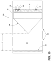
- FIGS. 10 and 11 are diagrammatic views of examples of electro-optic liquid sensors that may be used in the claimed method which are generally indicated as 16A and 16B, respectively.
- the sensor 16A,16B includes a light source 20, a photo sensor (or light detector) 22, a prism 24, and a reflective optical member 26 (which may also be referred to as an optical shield), which may be generally disposed within a housing 28.
- the housing 28 may include one or more liquid ports 30 for permitting liquid to flow into and out of a chamber 32 of the housing 28.
- the chamber 32 may define a gap between the prism 24 (or an extent thereof) and the optical member 26, such as generally illustrated in connection with dimension d.
- d may be about 2,54 cm (an inch) or less. Of course, other dimensions may be employed as appropriate for particular applications.
- electro-optic liquid sensors may include an optically isolating chassis 34.
- An optically isolating chassis 34 may, for example, be disposed between two separate photo sensors 22 and/or between a photo sensor 22 and a light source 20.
- an optically isolating chassis may additionally be disposed on a side of the same side of a prism 24 as a light source 20 and/or opposite a reflective optical member 26.
- one or more photo sensors and a light source may be provided between portions or segments of an optically isolating chassis.
- an LED is used to change a light intensity (e.g., high/low) as necessary or desired to interrogate a sensor with respect to an in-fluid or an in-air state.
- the sensors use a photo-IC (e.g., a photo diode-based sensor) or, according to examples not encompassed by the wording of the claims, may use a transistor.
- a high dynamic range e.g., to allow for reliable fluid absence/presence detection
- a BIT function may be modified or improved to include an optical power compensation circuit (such as a photo diode), which may provide for more consistent/continuous interrogation of a light source irrespective of a sensor's physical environment (e.g. in-air or in-fluid).
- an optical power compensation circuit such as a photo diode
- the inclusion of a photo diode based circuit, which may operate in a linear region may address certain limitations.
- the inclusion of a timing circuit caps an amount of energy that is permitted through a circuit.
- including a photo diode based circuit may provide for a better operational dynamic range, may reduce sensor power management requirements, may improve sensor reliability (for example by lowering thermal stresses on primary components), many improve sensor safety in fuel/gaseous environments, and/or may better control sensor threshold sensitivity.
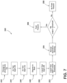
- FIG. 12 an embodiment of a method 140 of operating an electro-optic sensor 16 according to the claimed invention is generally illustrated.
- the method may have a number of similarities to the method disclosed in connection with FIG. 6 .
- the illustrated embodiment of FIG. 12 includes, inter alia, a timer that is associated with and/or follow a built-in-test step (e.g., step 142). If there is no timeout occurrence or event associated with the timer, the method proceeds with (i) driving receiver at 1st threshold (step 146) and/or (ii) driving light source at 1st frequency and intensity (step 144). However, if there is a timeout occurrence or event associated with the timer, the methods moves to a timeout related action (for example, step 170) - which may, for example, indicate that a sensor is not functioning.
- a timeout related action for example, step 170
- FIG. 13 is a diagrammatic view of an example of an in-liquid electro-optic testing configuration/arrangement, which is generally indicated as 16C.
- the configuration/arrangement 16C may include a sensor prism 24', a light source 20', and a photo sensor 22'.
- a light path ( LP ) is shown in a fluid.
- a sensor prism 24' may be immersed in a fluid.
- residual light reflection ( RL ) within the prism may be directed as indicated.
- Such residual light reflection ( RL ) may comprise an always present low level light signal.
- a system can be provided that, inter alia, monitors sensor performance (e.g., health) continuously (e.g., in real time) regardless of whether a sensor head is in liquid or in air.
- sensor performance e.g., health
- continuously e.g., in real time
- references to a single element are not necessarily so limited and may include one or more of such element.
- Any directional references e.g., plus, minus, upper, lower, upward, downward, left, right, leftward, rightward, top, bottom, above, below, vertical, horizontal, clockwise, and counterclockwise
- Any directional references are only used for identification purposes to aid the reader's understanding of the present invention, and do not create limitations, particularly as to the position, orientation, or use of embodiments.
- joinder references are to be construed broadly and may include intermediate members between a connection of elements and relative movement between elements. As such, joinder references do not necessarily imply that two elements are directly connected/coupled and in fixed relation to each other.
- the use of "e.g.” in the specification is to be construed broadly and is used to provide non-limiting examples of embodiments of the invention, and the invention is not limited to such examples.
- Uses of "and” and “or” are to be construed broadly (e.g., to be treated as "and/or”). For example and without limitation, uses of "and” do not necessarily require all elements or features listed, and uses of "or” are intended to be inclusive unless such a construction would be illogical.
Landscapes
- Physics & Mathematics (AREA)
- Electromagnetism (AREA)
- General Physics & Mathematics (AREA)
- Thermal Sciences (AREA)
- Fluid Mechanics (AREA)
- Investigating Or Analysing Materials By Optical Means (AREA)
- Measurement Of Levels Of Liquids Or Fluent Solid Materials (AREA)
Claims (7)
- Verfahren (140) zum Betreiben eines elektrooptischen Sensors (16), wobei das Verfahren umfasst:Anordnen mindestens eines Teils des elektrooptischen Sensors (16) in einer Flüssigkeitskammer (14);Testen auf das Auftreten einer Zeitüberschreitung, die dem Zeitgeber zugeordnet ist, über einen Zeitgeber, wobei der Zeitgeber eine Zeitgeberschaltung einschließt;wenn das Auftreten einer Zeitüberschreitung vorliegt, dann Anzeigen, dass der elektrooptische Sensor (16) nicht funktioniert;wenn kein Auftreten einer Zeitüberschreitung, die dem Zeitgeber zugeordnet ist, vorliegt, dann:Bereitstellen von Licht von einer Lichtquelle (20) des elektrooptischen Sensors (16) mit einer ersten Intensität;Ansteuern eines Lichtdetektors (22) des elektrooptischen Sensors (16) mit einem ersten Empfindlichkeitsniveau;Empfangen einer ersten Lichtmenge von der Lichtquelle (20) über den Lichtdetektor (22);Bestimmen, ob Flüssigkeit in der Flüssigkeitskammer (14) vorhanden ist, in Abhängigkeit von der ersten Lichtmenge;Bereitstellen von Licht von der Lichtquelle (20) mit einer zweiten Intensität;Ansteuern des Lichtdetektors (22) mit einem zweiten Empfindlichkeitsniveau;Empfangen einer zweiten Lichtmenge von der Lichtquelle (20) über den Lichtdetektor (22);Bestätigen, ob Flüssigkeit in der Flüssigkeitskammer (14) vorhanden ist, in Abhängigkeit von der zweiten Lichtmenge;wobei sich das erste Empfindlichkeitsniveau von dem zweiten Empfindlichkeitsniveau unterscheidet; undwobei der elektrooptische Sensor (16) ein Prisma (24) und ein reflektierendes optisches Element (26) einschließt, wobei das reflektierende optische Element (26) so angeordnet ist, dass es von der Lichtquelle (20) emittiertes Licht zu dem Lichtdetektor (22) reflektiert, wenn sich eine Flüssigkeit zwischen der Lichtquelle (20) und dem reflektierenden optischen Element (26) befindet;wobei der elektrooptische Sensor (16) einen Sensor auf Fotodiodenbasis einschließt,die Lichtquelle (20) eine LED einschließt, unddie Zeitgeberschaltung so konfiguriert ist, dass sie eine Energiemenge durch einen Schaltkreis des elektrooptischen Sensors (16) begrenzt.
- Verfahren nach Anspruch 1, wobei das Bestimmen, ob Flüssigkeit in der Flüssigkeitskammer (14) vorhanden ist, gemäß der ersten Lichtmenge das Vergleichen der ersten Lichtmenge mit einem Schwellenwert, und das Bestimmen, dass keine Flüssigkeit vorhanden ist, wenn die erste Lichtmenge größer als der Schwellenwert ist, einschließt.
- Verfahren nach Anspruch 1, wobei, wenn die erste Lichtmenge kleiner als ein erster Schwellenwert ist, die zweite Intensität größer als die erste Intensität ist und das zweite Empfindlichkeitsniveau empfindlicher als das erste Empfindlichkeitsniveau ist, -dann das Bestätigen, ob Flüssigkeit in der Flüssigkeitskammer (14) vorhanden ist, das Bestätigen, dass Flüssigkeit vorhanden ist, wenn die zweite Lichtmenge größer als ein zweiter Schwellenwert ist, und das Bestimmen, dass ein Fehler aufgetreten ist, wenn die zweite Lichtmenge nicht größer als der zweite Schwellenwert ist, einschließt.
- Verfahren nach Anspruch 3, wobei, wenn die erste Lichtmenge größer als der erste Schwellenwert ist, die zweite Intensität kleiner als die erste Intensität ist und das zweite Empfindlichkeitsniveau weniger empfindlich als das erste Empfindlichkeitsniveau ist, dann das Bestätigen, ob Flüssigkeit in der Flüssigkeitskammer (14) vorhanden ist, das Bestätigen, dass keine Flüssigkeit vorhanden ist, wenn eine dritte Lichtmenge kleiner als ein dritter Schwellenwert ist, und das Bestimmen, dass ein Fehler aufgetreten ist, wenn die dritte Lichtmenge nicht kleiner als der dritte Schwellenwert ist, einschließt.
- Verfahren nach Anspruch 1, wobei der Lichtdetektor (22) eine optische Kopfbaugruppe (300), die in der Flüssigkeitskammer (14) angeordnet ist, und eine elektronische Modulbaugruppe (310) einschließt, die außerhalb der Flüssigkeitskammer (14) angeordnet ist.
- Verfahren nach Anspruch 5, wobei die optische Kopfbaugruppe mit der elektronischen Modulbaugruppe (310) über ein oder mehrere faseroptische Kabel (312, 330) verbunden ist.
- Verfahren nach Anspruch 6, wobei das eine oder die mehreren faseroptischen Kabel (312, 330) eine einzelne Faser einschließen.
Applications Claiming Priority (2)
| Application Number | Priority Date | Filing Date | Title |
|---|---|---|---|
| US201962869789P | 2019-07-02 | 2019-07-02 | |
| US16/914,922 US11300438B2 (en) | 2019-07-02 | 2020-06-29 | Electro-optic liquid sensor |
Publications (2)
| Publication Number | Publication Date |
|---|---|
| EP3760985A1 EP3760985A1 (de) | 2021-01-06 |
| EP3760985B1 true EP3760985B1 (de) | 2025-05-28 |
Family
ID=71452065
Family Applications (1)
| Application Number | Title | Priority Date | Filing Date |
|---|---|---|---|
| EP20183566.7A Active EP3760985B1 (de) | 2019-07-02 | 2020-07-01 | Elektrooptischer flüssigkeitssensor |
Country Status (2)
| Country | Link |
|---|---|
| US (1) | US11300438B2 (de) |
| EP (1) | EP3760985B1 (de) |
Families Citing this family (3)
| Publication number | Priority date | Publication date | Assignee | Title |
|---|---|---|---|---|
| US10620032B2 (en) | 2013-09-10 | 2020-04-14 | Eaton Intelligent Power Limited | Electro-optic liquid sensor with the use of reflected residual light to enable a test of the sensor |
| US11977166B2 (en) * | 2019-08-16 | 2024-05-07 | WeRide Corp. | Optical system, method and apparatus for diagnosing the same |
| US20230236058A1 (en) * | 2022-01-21 | 2023-07-27 | Eaton Intelligent Power Limited | Methods and systems for testing electro optic sensors |
Citations (1)
| Publication number | Priority date | Publication date | Assignee | Title |
|---|---|---|---|---|
| KR20080002056A (ko) * | 2006-06-30 | 2008-01-04 | 한국 고덴시 주식회사 | 광학식 액체 레벨 센서 및 그의 제조 방법 |
Family Cites Families (9)
| Publication number | Priority date | Publication date | Assignee | Title |
|---|---|---|---|---|
| US4354180A (en) * | 1980-12-19 | 1982-10-12 | Genelco, Inc. | Electro-optical liquid level sensor |
| US5257539A (en) * | 1992-05-21 | 1993-11-02 | Gale Danny E | Electronic oil level indicator |
| US5514920A (en) * | 1993-12-30 | 1996-05-07 | Key; William D. | Fuel dispenser leak detector |
| US6049088A (en) * | 1998-01-09 | 2000-04-11 | Scully Signal Company | Fluid overfill probe with anti-reflective guard |
| US6040897A (en) * | 1998-04-29 | 2000-03-21 | Laser Technology, Inc. | Remote sensor head for laser level measurement devices |
| JP2009014660A (ja) | 2007-07-09 | 2009-01-22 | Tsuuden:Kk | 2液漏液センサ及びそのためのプリズム |
| US10620032B2 (en) * | 2013-09-10 | 2020-04-14 | Eaton Intelligent Power Limited | Electro-optic liquid sensor with the use of reflected residual light to enable a test of the sensor |
| WO2015038514A1 (en) | 2013-09-10 | 2015-03-19 | Eaton Corporation | Electro-optic liquid sensor enabling in-liquid testing |
| EP3318849A1 (de) | 2016-11-08 | 2018-05-09 | Eaton Corporation | Elektrooptischer flüssigkeitssensor |
-
2020
- 2020-06-29 US US16/914,922 patent/US11300438B2/en active Active
- 2020-07-01 EP EP20183566.7A patent/EP3760985B1/de active Active
Patent Citations (1)
| Publication number | Priority date | Publication date | Assignee | Title |
|---|---|---|---|---|
| KR20080002056A (ko) * | 2006-06-30 | 2008-01-04 | 한국 고덴시 주식회사 | 광학식 액체 레벨 센서 및 그의 제조 방법 |
Non-Patent Citations (1)
| Title |
|---|
| ANONYMOUS: "Watchdog timer - Wikipedia", 7 December 2014 (2014-12-07), XP055619509, Retrieved from the Internet <URL:https://en.wikipedia.org/w/index.php?title=Watchdog_timer&oldid=637036335> [retrieved on 20190906] * |
Also Published As
| Publication number | Publication date |
|---|---|
| US20210003441A1 (en) | 2021-01-07 |
| EP3760985A1 (de) | 2021-01-06 |
| US11300438B2 (en) | 2022-04-12 |
Similar Documents
| Publication | Publication Date | Title |
|---|---|---|
| US11680840B2 (en) | Method of operating an electro-optic liquid sensor to determine presence of liquid based on an amount of reflected light | |
| US10627281B2 (en) | Electro-optic liquid sensor enabling in-liquid testing | |
| US11300438B2 (en) | Electro-optic liquid sensor | |
| US20200309909A1 (en) | Time of flight assembly, terminal device and control method for time of flight assembly | |
| US20120126991A1 (en) | Device and Method of Determining Safety in a Battery Pack | |
| EP3318849A1 (de) | Elektrooptischer flüssigkeitssensor | |
| WO2017015960A1 (zh) | 基于声发射的健康监测方法和系统 | |
| US20170003118A1 (en) | Bolt sensor | |
| EP2604991B1 (de) | Flüssigkeitsdetektor und system zur identifizierung von flüssigkeiten | |
| CN111794954A (zh) | 隔膜破裂监测 | |
| CN110260947A (zh) | 一种光纤液位传感器及传感方法 | |
| CN113405703B (zh) | 一种光学传感器及消防报警装置 | |
| KR100726935B1 (ko) | 정전용량형 누수 감지 센서 | |
| EP3859288B1 (de) | Elektrooptischer sensor | |
| JP5415376B2 (ja) | センサヘッド、および光学式センサ | |
| GB2036326A (en) | Liquid level sensor | |
| EP2144207A1 (de) | Glasfasereindringungsschutzsystem | |
| US10795148B2 (en) | Micromechanical component, micromirror-based laser system, and method for monitoring a micromirror-based laser system comprising dual sensor diodes for sensing temperature and light intensity | |
| CN205451348U (zh) | 一种智能防盗地垫 | |
| CN112362134A (zh) | 一种液面位置检测装置和检测方法 | |
| US8558156B2 (en) | Device for capturing and preserving an energy beam which penetrates into an interior of said device and method therefor | |
| CN106990072A (zh) | 一种开放式气体浓度检测装置 | |
| CN205451349U (zh) | 一种光纤智能防盗系统 | |
| US9329079B2 (en) | Reflector having a detector to detect the presence of light beam against the reflector and to indicate a state of alignment used in a reflex mode detection device | |
| KR102689347B1 (ko) | 누액감지센서 |
Legal Events
| Date | Code | Title | Description |
|---|---|---|---|
| PUAI | Public reference made under article 153(3) epc to a published international application that has entered the european phase |
Free format text: ORIGINAL CODE: 0009012 |
|
| STAA | Information on the status of an ep patent application or granted ep patent |
Free format text: STATUS: REQUEST FOR EXAMINATION WAS MADE |
|
| 17P | Request for examination filed |
Effective date: 20200701 |
|
| AK | Designated contracting states |
Kind code of ref document: A1 Designated state(s): AL AT BE BG CH CY CZ DE DK EE ES FI FR GB GR HR HU IE IS IT LI LT LU LV MC MK MT NL NO PL PT RO RS SE SI SK SM TR |
|
| AX | Request for extension of the european patent |
Extension state: BA ME |
|
| STAA | Information on the status of an ep patent application or granted ep patent |
Free format text: STATUS: EXAMINATION IS IN PROGRESS |
|
| 17Q | First examination report despatched |
Effective date: 20230119 |
|
| P01 | Opt-out of the competence of the unified patent court (upc) registered |
Effective date: 20230521 |
|
| GRAP | Despatch of communication of intention to grant a patent |
Free format text: ORIGINAL CODE: EPIDOSNIGR1 |
|
| STAA | Information on the status of an ep patent application or granted ep patent |
Free format text: STATUS: GRANT OF PATENT IS INTENDED |
|
| INTG | Intention to grant announced |
Effective date: 20241219 |
|
| GRAS | Grant fee paid |
Free format text: ORIGINAL CODE: EPIDOSNIGR3 |
|
| GRAA | (expected) grant |
Free format text: ORIGINAL CODE: 0009210 |
|
| STAA | Information on the status of an ep patent application or granted ep patent |
Free format text: STATUS: THE PATENT HAS BEEN GRANTED |
|
| AK | Designated contracting states |
Kind code of ref document: B1 Designated state(s): AL AT BE BG CH CY CZ DE DK EE ES FI FR GB GR HR HU IE IS IT LI LT LU LV MC MK MT NL NO PL PT RO RS SE SI SK SM TR |
|
| REG | Reference to a national code |
Ref country code: GB Ref legal event code: FG4D |
|
| REG | Reference to a national code |
Ref country code: CH Ref legal event code: EP |
|
| REG | Reference to a national code |
Ref country code: IE Ref legal event code: FG4D Ref country code: DE Ref legal event code: R096 Ref document number: 602020051948 Country of ref document: DE |
|
| REG | Reference to a national code |
Ref country code: NL Ref legal event code: MP Effective date: 20250528 |
|
| PG25 | Lapsed in a contracting state [announced via postgrant information from national office to epo] |
Ref country code: FI Free format text: LAPSE BECAUSE OF FAILURE TO SUBMIT A TRANSLATION OF THE DESCRIPTION OR TO PAY THE FEE WITHIN THE PRESCRIBED TIME-LIMIT Effective date: 20250528 Ref country code: ES Free format text: LAPSE BECAUSE OF FAILURE TO SUBMIT A TRANSLATION OF THE DESCRIPTION OR TO PAY THE FEE WITHIN THE PRESCRIBED TIME-LIMIT Effective date: 20250528 |
|
| PGFP | Annual fee paid to national office [announced via postgrant information from national office to epo] |
Ref country code: DE Payment date: 20250829 Year of fee payment: 6 |
|
| REG | Reference to a national code |
Ref country code: LT Ref legal event code: MG9D |
|
| PG25 | Lapsed in a contracting state [announced via postgrant information from national office to epo] |
Ref country code: GR Free format text: LAPSE BECAUSE OF FAILURE TO SUBMIT A TRANSLATION OF THE DESCRIPTION OR TO PAY THE FEE WITHIN THE PRESCRIBED TIME-LIMIT Effective date: 20250829 Ref country code: NO Free format text: LAPSE BECAUSE OF FAILURE TO SUBMIT A TRANSLATION OF THE DESCRIPTION OR TO PAY THE FEE WITHIN THE PRESCRIBED TIME-LIMIT Effective date: 20250828 |
|
| PG25 | Lapsed in a contracting state [announced via postgrant information from national office to epo] |
Ref country code: PL Free format text: LAPSE BECAUSE OF FAILURE TO SUBMIT A TRANSLATION OF THE DESCRIPTION OR TO PAY THE FEE WITHIN THE PRESCRIBED TIME-LIMIT Effective date: 20250528 Ref country code: NL Free format text: LAPSE BECAUSE OF FAILURE TO SUBMIT A TRANSLATION OF THE DESCRIPTION OR TO PAY THE FEE WITHIN THE PRESCRIBED TIME-LIMIT Effective date: 20250528 |
|
| PG25 | Lapsed in a contracting state [announced via postgrant information from national office to epo] |
Ref country code: BG Free format text: LAPSE BECAUSE OF FAILURE TO SUBMIT A TRANSLATION OF THE DESCRIPTION OR TO PAY THE FEE WITHIN THE PRESCRIBED TIME-LIMIT Effective date: 20250528 |
|
| PGFP | Annual fee paid to national office [announced via postgrant information from national office to epo] |
Ref country code: GB Payment date: 20250828 Year of fee payment: 6 |
|
| PG25 | Lapsed in a contracting state [announced via postgrant information from national office to epo] |
Ref country code: HR Free format text: LAPSE BECAUSE OF FAILURE TO SUBMIT A TRANSLATION OF THE DESCRIPTION OR TO PAY THE FEE WITHIN THE PRESCRIBED TIME-LIMIT Effective date: 20250528 |
|
| PGFP | Annual fee paid to national office [announced via postgrant information from national office to epo] |
Ref country code: FR Payment date: 20250829 Year of fee payment: 6 |
|
| PG25 | Lapsed in a contracting state [announced via postgrant information from national office to epo] |
Ref country code: RS Free format text: LAPSE BECAUSE OF FAILURE TO SUBMIT A TRANSLATION OF THE DESCRIPTION OR TO PAY THE FEE WITHIN THE PRESCRIBED TIME-LIMIT Effective date: 20250828 |
|
| PG25 | Lapsed in a contracting state [announced via postgrant information from national office to epo] |
Ref country code: IS Free format text: LAPSE BECAUSE OF FAILURE TO SUBMIT A TRANSLATION OF THE DESCRIPTION OR TO PAY THE FEE WITHIN THE PRESCRIBED TIME-LIMIT Effective date: 20250928 |
|
| PG25 | Lapsed in a contracting state [announced via postgrant information from national office to epo] |
Ref country code: LV Free format text: LAPSE BECAUSE OF FAILURE TO SUBMIT A TRANSLATION OF THE DESCRIPTION OR TO PAY THE FEE WITHIN THE PRESCRIBED TIME-LIMIT Effective date: 20250528 |
|
| REG | Reference to a national code |
Ref country code: AT Ref legal event code: MK05 Ref document number: 1798818 Country of ref document: AT Kind code of ref document: T Effective date: 20250528 |
|
| PG25 | Lapsed in a contracting state [announced via postgrant information from national office to epo] |
Ref country code: DK Free format text: LAPSE BECAUSE OF FAILURE TO SUBMIT A TRANSLATION OF THE DESCRIPTION OR TO PAY THE FEE WITHIN THE PRESCRIBED TIME-LIMIT Effective date: 20250528 Ref country code: SM Free format text: LAPSE BECAUSE OF FAILURE TO SUBMIT A TRANSLATION OF THE DESCRIPTION OR TO PAY THE FEE WITHIN THE PRESCRIBED TIME-LIMIT Effective date: 20250528 Ref country code: AT Free format text: LAPSE BECAUSE OF FAILURE TO SUBMIT A TRANSLATION OF THE DESCRIPTION OR TO PAY THE FEE WITHIN THE PRESCRIBED TIME-LIMIT Effective date: 20250528 |
|
| PG25 | Lapsed in a contracting state [announced via postgrant information from national office to epo] |
Ref country code: CZ Free format text: LAPSE BECAUSE OF FAILURE TO SUBMIT A TRANSLATION OF THE DESCRIPTION OR TO PAY THE FEE WITHIN THE PRESCRIBED TIME-LIMIT Effective date: 20250528 |
|
| PG25 | Lapsed in a contracting state [announced via postgrant information from national office to epo] |
Ref country code: EE Free format text: LAPSE BECAUSE OF FAILURE TO SUBMIT A TRANSLATION OF THE DESCRIPTION OR TO PAY THE FEE WITHIN THE PRESCRIBED TIME-LIMIT Effective date: 20250528 |
|
| PG25 | Lapsed in a contracting state [announced via postgrant information from national office to epo] |
Ref country code: SK Free format text: LAPSE BECAUSE OF FAILURE TO SUBMIT A TRANSLATION OF THE DESCRIPTION OR TO PAY THE FEE WITHIN THE PRESCRIBED TIME-LIMIT Effective date: 20250528 |
|
| PG25 | Lapsed in a contracting state [announced via postgrant information from national office to epo] |
Ref country code: IT Free format text: LAPSE BECAUSE OF FAILURE TO SUBMIT A TRANSLATION OF THE DESCRIPTION OR TO PAY THE FEE WITHIN THE PRESCRIBED TIME-LIMIT Effective date: 20250528 |
|
| REG | Reference to a national code |
Ref country code: CH Ref legal event code: H13 Free format text: ST27 STATUS EVENT CODE: U-0-0-H10-H13 (AS PROVIDED BY THE NATIONAL OFFICE) Effective date: 20260224 |
|
| REG | Reference to a national code |
Ref country code: DE Ref legal event code: R097 Ref document number: 602020051948 Country of ref document: DE |
|
| PG25 | Lapsed in a contracting state [announced via postgrant information from national office to epo] |
Ref country code: RO Free format text: LAPSE BECAUSE OF FAILURE TO SUBMIT A TRANSLATION OF THE DESCRIPTION OR TO PAY THE FEE WITHIN THE PRESCRIBED TIME-LIMIT Effective date: 20250528 Ref country code: LU Free format text: LAPSE BECAUSE OF NON-PAYMENT OF DUE FEES Effective date: 20250701 |
|
| REG | Reference to a national code |
Ref country code: BE Ref legal event code: MM Effective date: 20250731 |
|
| PLBE | No opposition filed within time limit |
Free format text: ORIGINAL CODE: 0009261 |
|
| STAA | Information on the status of an ep patent application or granted ep patent |
Free format text: STATUS: NO OPPOSITION FILED WITHIN TIME LIMIT |
|
| REG | Reference to a national code |
Ref country code: CH Ref legal event code: L10 Free format text: ST27 STATUS EVENT CODE: U-0-0-L10-L00 (AS PROVIDED BY THE NATIONAL OFFICE) Effective date: 20260409 |
|
| PG25 | Lapsed in a contracting state [announced via postgrant information from national office to epo] |
Ref country code: BE Free format text: LAPSE BECAUSE OF NON-PAYMENT OF DUE FEES Effective date: 20250731 |
|
| PG25 | Lapsed in a contracting state [announced via postgrant information from national office to epo] |
Ref country code: CH Free format text: LAPSE BECAUSE OF NON-PAYMENT OF DUE FEES Effective date: 20250731 |
|
| 26N | No opposition filed |
Effective date: 20260303 |