EP3760959A1 - Heat dissipation device - Google Patents
Heat dissipation device Download PDFInfo
- Publication number
- EP3760959A1 EP3760959A1 EP20181545.3A EP20181545A EP3760959A1 EP 3760959 A1 EP3760959 A1 EP 3760959A1 EP 20181545 A EP20181545 A EP 20181545A EP 3760959 A1 EP3760959 A1 EP 3760959A1
- Authority
- EP
- European Patent Office
- Prior art keywords
- water cooling
- heat
- heat dissipation
- fins
- dissipation device
- Prior art date
- Legal status (The legal status is an assumption and is not a legal conclusion. Google has not performed a legal analysis and makes no representation as to the accuracy of the status listed.)
- Granted
Links
Images


Classifications
-
- F—MECHANICAL ENGINEERING; LIGHTING; HEATING; WEAPONS; BLASTING
- F28—HEAT EXCHANGE IN GENERAL
- F28D—HEAT-EXCHANGE APPARATUS, NOT PROVIDED FOR IN ANOTHER SUBCLASS, IN WHICH THE HEAT-EXCHANGE MEDIA DO NOT COME INTO DIRECT CONTACT
- F28D15/00—Heat-exchange apparatus with the intermediate heat-transfer medium in closed tubes passing into or through the conduit walls ; Heat-exchange apparatus employing intermediate heat-transfer medium or bodies
- F28D15/02—Heat-exchange apparatus with the intermediate heat-transfer medium in closed tubes passing into or through the conduit walls ; Heat-exchange apparatus employing intermediate heat-transfer medium or bodies in which the medium condenses and evaporates, e.g. heat pipes
- F28D15/0275—Arrangements for coupling heat-pipes together or with other structures, e.g. with base blocks; Heat pipe cores
-
- H—ELECTRICITY
- H05—ELECTRIC TECHNIQUES NOT OTHERWISE PROVIDED FOR
- H05K—PRINTED CIRCUITS; CASINGS OR CONSTRUCTIONAL DETAILS OF ELECTRIC APPARATUS; MANUFACTURE OF ASSEMBLAGES OF ELECTRICAL COMPONENTS
- H05K7/00—Constructional details common to different types of electric apparatus
- H05K7/20—Modifications to facilitate cooling, ventilating, or heating
- H05K7/20218—Modifications to facilitate cooling, ventilating, or heating using a liquid coolant without phase change in electronic enclosures
- H05K7/20272—Accessories for moving fluid, for expanding fluid, for connecting fluid conduits, for distributing fluid, for removing gas or for preventing leakage, e.g. pumps, tanks or manifolds
-
- H—ELECTRICITY
- H05—ELECTRIC TECHNIQUES NOT OTHERWISE PROVIDED FOR
- H05K—PRINTED CIRCUITS; CASINGS OR CONSTRUCTIONAL DETAILS OF ELECTRIC APPARATUS; MANUFACTURE OF ASSEMBLAGES OF ELECTRICAL COMPONENTS
- H05K7/00—Constructional details common to different types of electric apparatus
- H05K7/20—Modifications to facilitate cooling, ventilating, or heating
- H05K7/20218—Modifications to facilitate cooling, ventilating, or heating using a liquid coolant without phase change in electronic enclosures
- H05K7/20254—Cold plates transferring heat from heat source to coolant
-
- H—ELECTRICITY
- H05—ELECTRIC TECHNIQUES NOT OTHERWISE PROVIDED FOR
- H05K—PRINTED CIRCUITS; CASINGS OR CONSTRUCTIONAL DETAILS OF ELECTRIC APPARATUS; MANUFACTURE OF ASSEMBLAGES OF ELECTRICAL COMPONENTS
- H05K7/00—Constructional details common to different types of electric apparatus
- H05K7/20—Modifications to facilitate cooling, ventilating, or heating
- H05K7/2029—Modifications to facilitate cooling, ventilating, or heating using a liquid coolant with phase change in electronic enclosures
- H05K7/20336—Heat pipes, e.g. wicks or capillary pumps
-
- H—ELECTRICITY
- H10—SEMICONDUCTOR DEVICES; ELECTRIC SOLID-STATE DEVICES NOT OTHERWISE PROVIDED FOR
- H10W—GENERIC PACKAGES, INTERCONNECTIONS, CONNECTORS OR OTHER CONSTRUCTIONAL DETAILS OF DEVICES COVERED BY CLASS H10
- H10W40/00—Arrangements for thermal protection or thermal control
- H10W40/40—Arrangements for thermal protection or thermal control involving heat exchange by flowing fluids
- H10W40/47—Arrangements for thermal protection or thermal control involving heat exchange by flowing fluids by flowing liquids, e.g. forced water cooling
-
- H—ELECTRICITY
- H10—SEMICONDUCTOR DEVICES; ELECTRIC SOLID-STATE DEVICES NOT OTHERWISE PROVIDED FOR
- H10W—GENERIC PACKAGES, INTERCONNECTIONS, CONNECTORS OR OTHER CONSTRUCTIONAL DETAILS OF DEVICES COVERED BY CLASS H10
- H10W40/00—Arrangements for thermal protection or thermal control
- H10W40/70—Fillings or auxiliary members in containers or in encapsulations for thermal protection or control
- H10W40/73—Fillings or auxiliary members in containers or in encapsulations for thermal protection or control for cooling by change of state
-
- F—MECHANICAL ENGINEERING; LIGHTING; HEATING; WEAPONS; BLASTING
- F28—HEAT EXCHANGE IN GENERAL
- F28D—HEAT-EXCHANGE APPARATUS, NOT PROVIDED FOR IN ANOTHER SUBCLASS, IN WHICH THE HEAT-EXCHANGE MEDIA DO NOT COME INTO DIRECT CONTACT
- F28D21/00—Heat-exchange apparatus not covered by any of the groups F28D1/00 - F28D20/00
- F28D2021/0019—Other heat exchangers for particular applications; Heat exchange systems not otherwise provided for
- F28D2021/0028—Other heat exchangers for particular applications; Heat exchange systems not otherwise provided for for cooling heat generating elements, e.g. for cooling electronic components or electric devices
- F28D2021/0029—Heat sinks
-
- H—ELECTRICITY
- H10—SEMICONDUCTOR DEVICES; ELECTRIC SOLID-STATE DEVICES NOT OTHERWISE PROVIDED FOR
- H10W—GENERIC PACKAGES, INTERCONNECTIONS, CONNECTORS OR OTHER CONSTRUCTIONAL DETAILS OF DEVICES COVERED BY CLASS H10
- H10W40/00—Arrangements for thermal protection or thermal control
- H10W40/20—Arrangements for cooling
- H10W40/22—Arrangements for cooling characterised by their shape, e.g. having conical or cylindrical projections
- H10W40/226—Arrangements for cooling characterised by their shape, e.g. having conical or cylindrical projections characterised by projecting parts, e.g. fins to increase surface area
Definitions
- the invention relates to a heat dissipation device, and in particular to a heat dissipation device capable of dissipating heat from a plurality of heat sources.
- a water cooling head heat dissipation device is often disposed on a circuit board to dissipate heat from a heat source on the circuit board.
- the common water cooling head heat dissipation devices may be categorized into closed water cooling structures and open water cooling structures; in either structure, a part of the water cooling head heat dissipation device is usually thermally coupled to the heat source, and the heat of the heat source is transmitted to heat dissipation fins through liquid, so as to dissipate the heat energy.
- the invention provides a heat dissipation device capable of dissipating heat from plural heat sources.
- the heat dissipation device provided in an embodiment of the invention is adapted to be disposed on a primary heat source and a secondary heat source.
- the heat dissipation device includes a water cooling head module and a heat conducting member.
- the water cooling head module is disposed on the primary heat source.
- the heat conducting member is thermally coupled to the secondary heat source and extends into the water cooling head module.
- the water cooling head module has a water cooling tank and a plurality of fins.
- the fins extend along a first direction and are arranged in parallel along a second direction in the water cooling tank.
- the fins sleeve on one portion of the heat conducting member in the second direction.
- the heat conducting member includes a heat pipe.
- the water cooling head module has a water cooling tank, a water inlet, a water outlet, and a plurality of fins.
- the water inlet and the water outlet respectively communicate with the water cooling tank.
- the fins extend along the first direction and are arranged in parallel along the second direction in the water cooling tank.
- the water cooling head module includes at least one side wall and at least one inner partition board.
- the at least one side wall extends along the first direction and is located on at least one side of fin, and the at least one inner partition board extends along the second direction and is connected to the at least one side wall and at least one outermost fin of the fins.
- the at least one side wall includes two side walls
- the at least one inner partition board includes two inner partition boards.
- the two side walls extend along the first direction and are located at both sides of the fins
- the two inner partition boards extend along the second direction and are connected to two outermost fins of the fins.
- the water inlet is located at one side of a line connecting the two side walls
- the water outlet is located at the other side of the line connecting the two side walls.
- the water cooling head module has a water cooling tank, a water inlet, a water outlet, and a plurality of fins.
- the water cooling tank includes a first region and a second region.
- the water inlet is connected to the first region, and the water outlet is connected to the second region.
- the fins extend from the first region to the second region.
- the heat conducting member has a first terminal, a second terminal opposite to the first terminal, and a middle segment located between the first terminal and the second terminal. The middle segment is thermally coupled to the secondary heat source, the first terminal extends into and communicates with the first region of the water cooling tank, and the second terminal extends into and communicates with the second region of the water cooling tank.
- the heat conducting member is a runner pipe, and an inner diameter of the first terminal of the runner pipe is greater than an inner diameter of the second terminal.
- the heat dissipation device further includes a heat sink disposed on the secondary heat source, and the heat conducting member is thermally coupled to the secondary heat source through the heat sink.
- the water cooling head module further includes a bottom plate disposed on the primary heat source, and the heat conducting member contacts the bottom plate.
- the water cooling head module further includes a bottom plate disposed on the primary heat source, and the heat conducting member is suspended from the bottom plate.
- the heat dissipation device provided in one or more embodiments of the invention includes the water cooling head module and the heat conducting member.
- the water cooling head module is thermally coupled to the primary heat source, one portion of the heat conducting member extends into the water cooling head module, and the other portion is thermally coupled to the secondary heat source.
- the heat dissipation device provided in one or more embodiments of the invention dissipates heat from plural heat sources at the same time with use of one water cooling head module.
- the heat dissipation device provided in one or more embodiments of the invention may achieve heat dissipation effects within a limited space in a more efficient manner and may be more extensively applied..
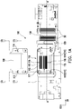
- FIG. 1A is a schematic assembly view illustrating that a heat dissipation device disposed on a circuit board according to an embodiment of the invention.
- a heat dissipation device 100 is adapted to be disposed on a primary heat source 10 (FIG. ID) and a secondary heat source 50 and is configured to dissipate heat from the primary heat source 10 and the secondary heat source 50.
- FIG. ID primary heat source 10
- FIG. ID primary heat source 10
- secondary heat source 50 the number of the primary heat source 10 shown in the drawings is plural; however, the number of the primary heat source 10 and the secondary heat source 50 should not be construed as a limitation in the invention.
- the heat dissipation device 100 provided in the invention is disposed on the circuit board 1 and is responsible for dissipating heat from the primary heat source 10 and the secondary heat source 50 on the circuit board 1.
- the circuit board 1 is an expansion card, for instance, the primary heat source 10 is, for instance, a graphics processing unit (GPU), and the secondary heat source 50 is, for instance, a metal-oxide-semiconductor field-effect transistor (MOSFET) chip.
- the heat source providing the heat dissipated by the heat dissipation device 100 is not limited in the invention, and the circuit board 1 may also be a motherboard.
- the structure of an upper cover 118 is omitted from the other figures.
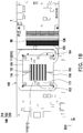
- FIG. 1B is a schematic top view illustrating that the heat dissipation device in FIG. 1A is disposed on a circuit board.
- the heat dissipation device 100 includes a water cooling head module 110 and a heat conducting member 120.
- the water cooling head module 110 is disposed on the primary heat source 10, one portion of the heat conducting member 120 extends into the water cooling head module 110, and the other portion is thermally coupled to the secondary heat source 50 on the circuit board 1.
- the primary heat source 10 provided in the embodiment is thermally coupled to the water cooling head module 110. Therefore, the heat energy generated by the primary heat source 10 is directly exported through the water cooling head module 110.
- the heat energy generated by the secondary heat source 50 provided in the embodiment may also be transmitted to the water cooling head module 110 through the heat conducting member 120 in a thermally conductive manner and also exported through the water cooling head module 110.
- the heat dissipation device provided in the embodiment 100 may achieve the overall heat dissipation of the circuit board 1 through one water cooling head module 110. That is, the heat dissipation device 100 provided in the embodiment may simultaneously dissipate the heat from the primary heat source 10 (CPU) and the secondary heat source 50 (other components) in no need of occupying too much space.
- the primary heat source 10 CPU
- the secondary heat source 50 other components
- the heat dissipation device provided in the embodiment 100 may also be equipped with a heat sink 130 on the secondary heat source 50, and the heat conducting member 120 is thermally coupled to the secondary heat source 50 through the heat sink 130.
- This design allows the heat sink 130 to simultaneously perform the heat conduction function and the function of dissipating the heat energy from the secondary heat source 50 to the air.
- the type and the form of the heat sink are not limited in the invention, and it is not required for the secondary heat source 50 to have the heat sink 130 thereon.
- the heat sink 130 may be partially disposed on the secondary heat source 50, or the heat conducting member 120 may be directly thermally coupled to the secondary heat source 50.
- the water cooling head module provided in the embodiment 110 has a water cooling tank 111, and the water cooling tank 111 includes the upper cover 118 ( FIG. 1A ).
- the water cooling tank 111 has an opening H ( FIG. 1C ) corresponding to the outer contour of the heat conducting member 120, and the shape of the heat conducting member 120 is a U shape according to the embodiment. Further, one section of the U-shaped heat conducting member 120 extends into the water cooling tank 111 through the opening H, and the other corresponding section of the U-shaped heat conducting member 120 is thermally coupled to the secondary heat source 50.
- the shape of the heat conducting member 120 should not be construed as a limitation in the invention.
- an O-ring (not shown) is further disposed between the inner wall of the opening H ( FIG. 1C ) and the heat conducting member 120 of the embodiment to prevent leakage of the heat dissipation fluid.
- the form of the O-ring is not limited in the invention; in other embodiments, other forms of anti-leakage structures or components may also be selected, and the invention is not limited thereto.
- the heat dissipation fluid in the liquid form inside the water cooling tank 111, for instance, in other embodiments, the heat dissipation fluid may be two-phase fluid or other heat dissipation media in other non-liquid form.
- the type of the heat dissipation medium is not limited in the invention.
- the heat conducting member 120 is a heat pipe.
- the heat pipe (the heat conducting member 120) is a closed cavity (not shown) containing two-phase fluid and dissipates heat through convection by the liquid and vapor changes of the two-phase fluid.
- the form of the heat conducting member 120 is not limited in the invention.
- the water cooling head module 110 includes a plurality of fins 112 disposed in the water cooling tank 111, and the fins 112 extend along a first direction D1 and are arranged in parallel along a second direction D2 on a bottom plate 117 of the water cooling tank 111.
- the bottom plate 117 of the water cooling tank 111 is coupled to the primary heat source 10.
- the heat pipe is disposed beside the fins 112 and spaced apart from the fins 112 by a distance.
- the heat pipe may be adhered to the fins, or the fins 112 sleeve on the heat pipe, which should however not be construed as a limitation in the invention.
- the arrangement manner of the fins 112 is not limited in the invention.
- the water cooling head module 110 provided in the embodiment has a water outlet 114 and a water inlet 113 communicating with the water cooling tank 111.
- the water outlet 114 and the water inlet 113 provided in the embodiment are disposed at the upper cover 118 of the water cooling head module 110, and the heat dissipation fluid flows into and out of the water cooling tank 111 in a direction perpendicular to the upper cover 118.
- the form and the location of the water outlet 114 and the water inlet 113 are not limited in the invention.
- the water outlet 114 and the water inlet 113 may also be disposed on a side of the water cooling tank 111 or may be designed in other appropriate manner, which should not be construed as a limitation in the invention.
- the water cooling head module 110 includes at least one side wall 115 and at least one inner partition board 116.
- the number of the side walls 115 is four, and the number of the inner partition boards 116 is two.
- Two of the four side walls 115 extend along the first direction D1 and are located at opposite sides of the fins 112, and the two inner partition boards 116 extend along the second direction D2 and are connected to the two side walls 115 and two outermost fins of the fins 112.
- the water inlet 113 is located at one side of a line connecting the two side walls 115, and the water outlet 114 is located at the other side of the line.
- the water cooling tank 111 includes a first region 1112 and a second region 1114.
- the water inlet 113 communicates with the first region 1112
- the water outlet 114 communicates with the second region 1114.
- the first region 1112 and the second region 1114 are partitioned by the inner partition board 116, and the fins 112 extend from the first region 1112 to the second region 1114.
- the heat dissipation fluid flows into the first region 1112 through the water inlet 113, flows into the second region 1114 through the fins 112, and then flows out of the water outlet 114.
- the inner partition boards 116 may also be disposed at other locations, or the water cooling tank 111 may be equipped with one or no inner partition board 116.
- one side of the fins 112 may directly lean against one of the side walls 115, and the inner partition boards 116 are connected to the other side (the outermost side) of the fins 112 and the corresponding side walls 115.
- the fins 112 may also be arranged in parallel from one of the side walls 115 (e.g., the side wall 115 on the upper portion of FIG. 1B ) to the other side wall 115 (e.g., the side wall 115 on the lower portion of FIG. 1B ) along the second direction D2, the water outlet 114 and the water inlet 113 are arranged along the first direction D1 at both terminals of the fins 112.
- the water cooling head module 110 does not need to be equipped with any inner partition board 116, and the heat dissipation fluid may still flow through the fins 112.
- the invention is not limited thereto, given that the fluid can flow toward the water outlet 114 through the fins 112 to ensure the good heat dissipation effects.
- the number of the side walls 115, the number of the inner partition boards 116, the location of the inner partition boards 116, and the location of the fins 112 are not limited in the invention.
- FIG. 1C is a schematic view illustrating that the heat dissipation device in FIG. 1A is disposed on a circuit board at another view angle.
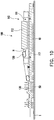
- FIG. ID is a schematic partial cross-sectional view illustrating that the heat dissipation device in FIG. 1A is disposed on a circuit board along a sectional line A-A'.
- the opening H of the water cooling tank 111 in the embodiment is higher than the bottom plate 117 of the water cooling tank 111. In other words, there is a certain distance between the edge of the opening H and the bottom plate 117. Hence, when the heat conducting member 120 is disposed on the opening H, the heat conducting member 120 is suspended from the bottom plate 117.
- the heat dissipation fluid may flow through the bottom surface of the heat conducting member 120, so as to increase the heat dissipation efficiency.
- the heat conducting member 120 may also directly contact the bottom plate 117, and the relative location of the heat conducting member 120 and the bottom plate 117 is not limited in the invention.
- the water cooling head module 110 of the heat dissipation device 100 may adopt a standard design, and the shape and the length of the heat conducting member 120 may be adjusted according to the location of the secondary heat source 50 generated heat to be dissipated by the heat conducting member 120.
- Designers may select a specific heat conducting member 120 matching the water cooling head module 110 of uniform size according to the location of the secondary heat source 50 on different circuit boards 1.
- the heat dissipation device 100 can have a good cost-performance ratio, and it is not necessary to make mold to produce specific heat dissipation device 100 tailored for the corresponding circuit board 1.
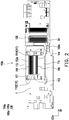
- FIG. 2 is a schematic view illustrating that a heat dissipation device is disposed on a circuit board according to another embodiment of the invention.
- the main difference between the heat dissipation device 100a provided in the embodiment and the heat dissipation device 100 provided in the previous embodiment lies in that in the fins 112a of the water cooling head module 110a sleeve on one portion of the heat conducting member 120a (the heat pipe) along the second direction D2.
- the heat dissipation fluid flows through the fins 112a, most of the heat dissipation fluid inevitably flows through the heat conducting member 120a, so that the conduction efficiency of the heat conducting member 120a may be increased.
- the fins 112a on the right side may sleeve on the heat conducting member 120a shown in FIG. 2 .
- the fins 112 (in the direction of FIG. 2 ) in the middle or on the left side may sleeve on the heat conducting member 120, which should not be construed as a limitation in the invention.
- FIG. 3 is a schematic top view illustrating that a heat dissipation device is disposed on a circuit board according to yet another embodiment of the invention.
- the main difference between the heat dissipation device provided in the embodiment 100b and the heat dissipation device provided in the previous embodiment lies in that the heat conducting member 120b in the embodiment is a hollow runner pipe. That is, the heat dissipation fluid in the water cooling tank 111b of the water cooling head module 110b provided in the embodiment may be circulated in the heat conducting member (the runner pipe) 120b and the water cooling tank 111b.
- the heat conducting member 120b (the runner pipe) has a first terminal 122b, a second terminal 124b opposite to the first terminal 122b, and a middle segment 126b located between the first terminal 122b and the second terminal 124b. Further, the middle segment 126b of the heat conducting member 120b (the runner pipe) is thermally coupled to the secondary heat source 50, the first terminal 122b of the heat conducting member 120b (the runner pipe) extends into and communicates with the first region 1112 of the water cooling tank 111, and the second terminal 124b extends into and communicates with the second region 1114 of the water cooling tank 111.
- the heat dissipation fluid may flow from the first region 1112 into the first terminal 122b of the heat conducting member 120b (the runner pipe) through the middle segment 126b and then flow from the second terminal 124b to the second region 1114, so as to bring the heat of the secondary heat source 50 to the second region 1114 of the water cooling tank 111b.
- an inner diameter of the first terminal 122b of the heat conducting member 120b is larger than an inner diameter of the second terminal 124b.
- the inner diameter of the heat conducting member 120b (the runner pipe) extending from the first terminal 122b to the middle segment 126b thermally coupled the secondary heat source 50 is greater than the inner diameter of the heat conducting member 120b (the runner pipe) extending from the middle segment 126b thermally coupled to the secondary heat source 50 to the second terminal 124b.
- the flow resistance of the first terminal 122b of the heat conducting member 120b may be smaller than the flow resistance of the second terminal 124b, so that the flow direction of the heat dissipation fluid is from the first region 1112 to the second region 1114, thereby preventing the heat dissipation fluid from flowing back and affecting the heat dissipation efficiency.
- the heat conducting member 120b (the runner pipe) provided in the embodiment allows the heat dissipation fluid to flow through a wider region, so as to efficiently dissipate the heat generated by the primary heat source 10 and the secondary heat source on the entire circuit board 1.
- the heat conducting member 120b (the runner pipe) is, for instance, a hollow copper pipe.
- the material of the runner pipe may be another thermally conductive metal material or another non-metallic thermally conductive material, which should not be construed as a limitation in the invention.
- the heat dissipation device provided in one or more embodiments of the invention includes the water cooling head module and the heat conducting member.
- the water cooling head module is thermally coupled to the primary heat source, one portion of the heat conducting member extends into the water cooling head module, and the other portion is thermally coupled to the secondary heat source.
- the heat dissipation device provided in one or more embodiments of the invention dissipates heat from plural heat sources at the same time with use of one water cooling head module.
- the heat dissipation device provided in one or more embodiments of the invention may achieve heat dissipation effects within a limited space in a more efficient manner and may be more extensively applied.
- the fins provided in one or more embodiments of the invention may directly sleeve on the heat conducting member, or the heat dissipation fluid may flow to the secondary heat source through the fins, so that the water cooling head module provided herein may achieve favorable heat dissipation.
Landscapes
- Engineering & Computer Science (AREA)
- Microelectronics & Electronic Packaging (AREA)
- Physics & Mathematics (AREA)
- Thermal Sciences (AREA)
- Life Sciences & Earth Sciences (AREA)
- Sustainable Development (AREA)
- Mechanical Engineering (AREA)
- General Engineering & Computer Science (AREA)
- Cooling Or The Like Of Electrical Apparatus (AREA)
Abstract
Description
- The invention relates to a heat dissipation device, and in particular to a heat dissipation device capable of dissipating heat from a plurality of heat sources.
- In general, a water cooling head heat dissipation device is often disposed on a circuit board to dissipate heat from a heat source on the circuit board. The common water cooling head heat dissipation devices may be categorized into closed water cooling structures and open water cooling structures; in either structure, a part of the water cooling head heat dissipation device is usually thermally coupled to the heat source, and the heat of the heat source is transmitted to heat dissipation fins through liquid, so as to dissipate the heat energy.
- Nowadays, computer devices have been developed to achieve high performance and occupy small size, and there are usually plural heat sources on a circuit board. In view of the above, how to dissipate heat from plural heat sources simultaneously and improve the overall heat dissipation effects with use of a simple device occupying small space has become an issue that requires prompt resolution.
- The invention provides a heat dissipation device capable of dissipating heat from plural heat sources.
- The heat dissipation device provided in an embodiment of the invention is adapted to be disposed on a primary heat source and a secondary heat source. The heat dissipation device includes a water cooling head module and a heat conducting member. The water cooling head module is disposed on the primary heat source. The heat conducting member is thermally coupled to the secondary heat source and extends into the water cooling head module.
- In an embodiment of the invention, the water cooling head module has a water cooling tank and a plurality of fins. The fins extend along a first direction and are arranged in parallel along a second direction in the water cooling tank. The fins sleeve on one portion of the heat conducting member in the second direction.
- In an embodiment of the invention, the heat conducting member includes a heat pipe.
- In an embodiment of the invention, the water cooling head module has a water cooling tank, a water inlet, a water outlet, and a plurality of fins. The water inlet and the water outlet respectively communicate with the water cooling tank. The fins extend along the first direction and are arranged in parallel along the second direction in the water cooling tank. The water cooling head module includes at least one side wall and at least one inner partition board. The at least one side wall extends along the first direction and is located on at least one side of fin, and the at least one inner partition board extends along the second direction and is connected to the at least one side wall and at least one outermost fin of the fins.
- In an embodiment of the invention, the at least one side wall includes two side walls, and the at least one inner partition board includes two inner partition boards. The two side walls extend along the first direction and are located at both sides of the fins, and the two inner partition boards extend along the second direction and are connected to two outermost fins of the fins. The water inlet is located at one side of a line connecting the two side walls, and the water outlet is located at the other side of the line connecting the two side walls.
- In an embodiment of the invention, the water cooling head module has a water cooling tank, a water inlet, a water outlet, and a plurality of fins. The water cooling tank includes a first region and a second region. The water inlet is connected to the first region, and the water outlet is connected to the second region. The fins extend from the first region to the second region. The heat conducting member has a first terminal, a second terminal opposite to the first terminal, and a middle segment located between the first terminal and the second terminal. The middle segment is thermally coupled to the secondary heat source, the first terminal extends into and communicates with the first region of the water cooling tank, and the second terminal extends into and communicates with the second region of the water cooling tank.
- In an embodiment of the invention, the heat conducting member is a runner pipe, and an inner diameter of the first terminal of the runner pipe is greater than an inner diameter of the second terminal.
- In an embodiment of the invention, the heat dissipation device further includes a heat sink disposed on the secondary heat source, and the heat conducting member is thermally coupled to the secondary heat source through the heat sink.
- In an embodiment of the invention, the water cooling head module further includes a bottom plate disposed on the primary heat source, and the heat conducting member contacts the bottom plate.
- In an embodiment of the invention, the water cooling head module further includes a bottom plate disposed on the primary heat source, and the heat conducting member is suspended from the bottom plate.
- Based on the above, the heat dissipation device provided in one or more embodiments of the invention includes the water cooling head module and the heat conducting member. The water cooling head module is thermally coupled to the primary heat source, one portion of the heat conducting member extends into the water cooling head module, and the other portion is thermally coupled to the secondary heat source. Thereby, the heat dissipation device provided in one or more embodiments of the invention dissipates heat from plural heat sources at the same time with use of one water cooling head module. In other words, the heat dissipation device provided in one or more embodiments of the invention may achieve heat dissipation effects within a limited space in a more efficient manner and may be more extensively applied..
-
-
FIG. 1A is a schematic assembly view illustrating that a heat dissipation device disposed on a circuit board according to an embodiment of the invention. -
FIG. 1B is a schematic top view illustrating that the heat dissipation device inFIG. 1A is disposed on a circuit board. -
FIG. 1C is a schematic view illustrating that the heat dissipation device inFIG. 1A is disposed on a circuit board at another view angle. - FIG. ID is a schematic partial cross-sectional view illustrating that the heat dissipation device in
FIG. 1A is disposed on a circuit board along a sectional line A-A'. -
FIG. 2 is a schematic view illustrating that a heat dissipation device is disposed on a circuit board according to another embodiment of the invention. -
FIG. 3 is a schematic top view illustrating that a heat dissipation device is disposed on a circuit board according to yet another embodiment of the invention. -
FIG. 1A is a schematic assembly view illustrating that a heat dissipation device disposed on a circuit board according to an embodiment of the invention. With reference toFIG. 1A , in the embodiment, aheat dissipation device 100 is adapted to be disposed on a primary heat source 10 (FIG. ID) and asecondary heat source 50 and is configured to dissipate heat from theprimary heat source 10 and thesecondary heat source 50. According to the embodiment, note that the number of theprimary heat source 10 shown in the drawings is one, for instance, and the number of thesecondary heat source 50 shown in the drawings is plural; however, the number of theprimary heat source 10 and thesecondary heat source 50 should not be construed as a limitation in the invention. - It is worth mentioning that the
heat dissipation device 100 provided in the invention is disposed on thecircuit board 1 and is responsible for dissipating heat from theprimary heat source 10 and thesecondary heat source 50 on thecircuit board 1. In the embodiment, thecircuit board 1 is an expansion card, for instance, theprimary heat source 10 is, for instance, a graphics processing unit (GPU), and thesecondary heat source 50 is, for instance, a metal-oxide-semiconductor field-effect transistor (MOSFET) chip. Certainly, the heat source providing the heat dissipated by theheat dissipation device 100 is not limited in the invention, and thecircuit board 1 may also be a motherboard. In addition, in order to clearly describe the internal structure of theheat dissipation device 100 of the invention, except forFIG. 1A , the structure of anupper cover 118 is omitted from the other figures. -
FIG. 1B is a schematic top view illustrating that the heat dissipation device inFIG. 1A is disposed on a circuit board. With reference toFIG. 1A andFIG. 1B , in the embodiment, theheat dissipation device 100 includes a watercooling head module 110 and aheat conducting member 120. The watercooling head module 110 is disposed on theprimary heat source 10, one portion of theheat conducting member 120 extends into the watercooling head module 110, and the other portion is thermally coupled to thesecondary heat source 50 on thecircuit board 1. Further, theprimary heat source 10 provided in the embodiment is thermally coupled to the watercooling head module 110. Therefore, the heat energy generated by theprimary heat source 10 is directly exported through the watercooling head module 110. In addition, the heat energy generated by thesecondary heat source 50 provided in the embodiment may also be transmitted to the watercooling head module 110 through theheat conducting member 120 in a thermally conductive manner and also exported through the watercooling head module 110. - In view of said design, the heat dissipation device provided in the
embodiment 100 may achieve the overall heat dissipation of thecircuit board 1 through one watercooling head module 110. That is, theheat dissipation device 100 provided in the embodiment may simultaneously dissipate the heat from the primary heat source 10 (CPU) and the secondary heat source 50 (other components) in no need of occupying too much space. - Besides, as shown in
FIG. 1A andFIG. 1B , the heat dissipation device provided in theembodiment 100 may also be equipped with aheat sink 130 on thesecondary heat source 50, and theheat conducting member 120 is thermally coupled to thesecondary heat source 50 through theheat sink 130. This design allows theheat sink 130 to simultaneously perform the heat conduction function and the function of dissipating the heat energy from thesecondary heat source 50 to the air. Certainly, the type and the form of the heat sink are not limited in the invention, and it is not required for thesecondary heat source 50 to have theheat sink 130 thereon. Alternatively, theheat sink 130 may be partially disposed on thesecondary heat source 50, or theheat conducting member 120 may be directly thermally coupled to thesecondary heat source 50. - As shown in
FIG. 1A andFIG. 1B , the water cooling head module provided in theembodiment 110 has awater cooling tank 111, and thewater cooling tank 111 includes the upper cover 118 (FIG. 1A ). In detail, thewater cooling tank 111 has an opening H (FIG. 1C ) corresponding to the outer contour of theheat conducting member 120, and the shape of theheat conducting member 120 is a U shape according to the embodiment. Further, one section of the U-shapedheat conducting member 120 extends into thewater cooling tank 111 through the opening H, and the other corresponding section of the U-shapedheat conducting member 120 is thermally coupled to thesecondary heat source 50. Certainly, the shape of theheat conducting member 120 should not be construed as a limitation in the invention. - Further, in the present embodiment, there may be heat dissipation fluid inside the
water cooling tank 111, for instance. Hence, an O-ring (not shown) is further disposed between the inner wall of the opening H (FIG. 1C ) and theheat conducting member 120 of the embodiment to prevent leakage of the heat dissipation fluid. Certainly, the form of the O-ring is not limited in the invention; in other embodiments, other forms of anti-leakage structures or components may also be selected, and the invention is not limited thereto. According to the embodiment, although there is the heat dissipation fluid in the liquid form inside thewater cooling tank 111, for instance, in other embodiments, the heat dissipation fluid may be two-phase fluid or other heat dissipation media in other non-liquid form. The type of the heat dissipation medium is not limited in the invention. - According to the embodiment, the
heat conducting member 120 is a heat pipe. In detail, the heat pipe (the heat conducting member 120) is a closed cavity (not shown) containing two-phase fluid and dissipates heat through convection by the liquid and vapor changes of the two-phase fluid. Certainly, the form of theheat conducting member 120 is not limited in the invention. - Further, in the embodiment, the water
cooling head module 110 includes a plurality offins 112 disposed in thewater cooling tank 111, and thefins 112 extend along a first direction D1 and are arranged in parallel along a second direction D2 on abottom plate 117 of thewater cooling tank 111. Thebottom plate 117 of thewater cooling tank 111 is coupled to theprimary heat source 10. In the embodiment, the heat pipe is disposed beside thefins 112 and spaced apart from thefins 112 by a distance. Certainly, in other embodiments, the heat pipe may be adhered to the fins, or thefins 112 sleeve on the heat pipe, which should however not be construed as a limitation in the invention. Besides, in other embodiments, the arrangement manner of thefins 112 is not limited in the invention. - As shown in
FIG. 1A andFIG. 1B , the watercooling head module 110 provided in the embodiment has awater outlet 114 and awater inlet 113 communicating with thewater cooling tank 111. InFIG. 1 , thewater outlet 114 and thewater inlet 113 provided in the embodiment are disposed at theupper cover 118 of the watercooling head module 110, and the heat dissipation fluid flows into and out of thewater cooling tank 111 in a direction perpendicular to theupper cover 118. Certainly, the form and the location of thewater outlet 114 and thewater inlet 113 are not limited in the invention. In other embodiments, thewater outlet 114 and thewater inlet 113 may also be disposed on a side of thewater cooling tank 111 or may be designed in other appropriate manner, which should not be construed as a limitation in the invention. - In detail, as shown in
FIG. 1B , in the embodiment, the watercooling head module 110 includes at least oneside wall 115 and at least oneinner partition board 116. For instance, in the embodiment, the number of theside walls 115 is four, and the number of theinner partition boards 116 is two. Two of the fourside walls 115 extend along the first direction D1 and are located at opposite sides of thefins 112, and the twoinner partition boards 116 extend along the second direction D2 and are connected to the twoside walls 115 and two outermost fins of thefins 112. In addition, thewater inlet 113 is located at one side of a line connecting the twoside walls 115, and thewater outlet 114 is located at the other side of the line. - Further, in the embodiment, the
water cooling tank 111 includes afirst region 1112 and asecond region 1114. Specifically, thewater inlet 113 communicates with thefirst region 1112, and thewater outlet 114 communicates with thesecond region 1114. Thefirst region 1112 and thesecond region 1114 are partitioned by theinner partition board 116, and thefins 112 extend from thefirst region 1112 to thesecond region 1114. Thereby, the heat dissipation fluid flows into thefirst region 1112 through thewater inlet 113, flows into thesecond region 1114 through thefins 112, and then flows out of thewater outlet 114. - Certainly, in other embodiments, the
inner partition boards 116 may also be disposed at other locations, or thewater cooling tank 111 may be equipped with one or noinner partition board 116. For instance, in an embodiment, one side of thefins 112 may directly lean against one of theside walls 115, and theinner partition boards 116 are connected to the other side (the outermost side) of thefins 112 and thecorresponding side walls 115. - Alternatively, in another embodiment, the
fins 112 may also be arranged in parallel from one of the side walls 115 (e.g., theside wall 115 on the upper portion ofFIG. 1B ) to the other side wall 115 (e.g., theside wall 115 on the lower portion ofFIG. 1B ) along the second direction D2, thewater outlet 114 and thewater inlet 113 are arranged along the first direction D1 at both terminals of thefins 112. Thereby, the watercooling head module 110 does not need to be equipped with anyinner partition board 116, and the heat dissipation fluid may still flow through thefins 112. Certainly, the invention is not limited thereto, given that the fluid can flow toward thewater outlet 114 through thefins 112 to ensure the good heat dissipation effects. Moreover, the number of theside walls 115, the number of theinner partition boards 116, the location of theinner partition boards 116, and the location of thefins 112 are not limited in the invention. -
FIG. 1C is a schematic view illustrating that the heat dissipation device inFIG. 1A is disposed on a circuit board at another view angle. FIG. ID is a schematic partial cross-sectional view illustrating that the heat dissipation device inFIG. 1A is disposed on a circuit board along a sectional line A-A'. As shown inFIG. 1C and FIG. ID, the opening H of thewater cooling tank 111 in the embodiment is higher than thebottom plate 117 of thewater cooling tank 111. In other words, there is a certain distance between the edge of the opening H and thebottom plate 117. Hence, when theheat conducting member 120 is disposed on the opening H, theheat conducting member 120 is suspended from thebottom plate 117. As such, the heat dissipation fluid may flow through the bottom surface of theheat conducting member 120, so as to increase the heat dissipation efficiency. Certainly, in other embodiments, theheat conducting member 120 may also directly contact thebottom plate 117, and the relative location of theheat conducting member 120 and thebottom plate 117 is not limited in the invention. - According to the embodiment, it is worth mentioning that the water
cooling head module 110 of theheat dissipation device 100 may adopt a standard design, and the shape and the length of theheat conducting member 120 may be adjusted according to the location of thesecondary heat source 50 generated heat to be dissipated by theheat conducting member 120. Designers may select a specificheat conducting member 120 matching the watercooling head module 110 of uniform size according to the location of thesecondary heat source 50 ondifferent circuit boards 1. As such, theheat dissipation device 100 can have a good cost-performance ratio, and it is not necessary to make mold to produce specificheat dissipation device 100 tailored for thecorresponding circuit board 1. - Other embodiments are provided below for explanation. The same or similar structural configurations, design principles, and technical effects in each embodiment are not further explained, but the design differences between the embodiments will be mainly described.
-
FIG. 2 is a schematic view illustrating that a heat dissipation device is disposed on a circuit board according to another embodiment of the invention. With reference toFIG. 2 , the main difference between theheat dissipation device 100a provided in the embodiment and theheat dissipation device 100 provided in the previous embodiment lies in that in thefins 112a of the watercooling head module 110a sleeve on one portion of theheat conducting member 120a (the heat pipe) along the second direction D2. As such, when the heat dissipation fluid flows through thefins 112a, most of the heat dissipation fluid inevitably flows through theheat conducting member 120a, so that the conduction efficiency of theheat conducting member 120a may be increased. - Note that that some of the
fins 112a on the right side (in the direction ofFIG. 2 ) may sleeve on theheat conducting member 120a shown inFIG. 2 . Certainly, in other embodiments, the fins 112 (in the direction ofFIG. 2 ) in the middle or on the left side may sleeve on theheat conducting member 120, which should not be construed as a limitation in the invention. -
FIG. 3 is a schematic top view illustrating that a heat dissipation device is disposed on a circuit board according to yet another embodiment of the invention. With reference toFIG. 3 , the main difference between the heat dissipation device provided in the embodiment 100b and the heat dissipation device provided in the previous embodiment lies in that theheat conducting member 120b in the embodiment is a hollow runner pipe. That is, the heat dissipation fluid in the water cooling tank 111b of the watercooling head module 110b provided in the embodiment may be circulated in the heat conducting member (the runner pipe) 120b and the water cooling tank 111b. - In detail, according to the embodiment, the
heat conducting member 120b (the runner pipe) has afirst terminal 122b, asecond terminal 124b opposite to thefirst terminal 122b, and amiddle segment 126b located between thefirst terminal 122b and thesecond terminal 124b. Further, themiddle segment 126b of theheat conducting member 120b (the runner pipe) is thermally coupled to thesecondary heat source 50, the first terminal 122b of theheat conducting member 120b (the runner pipe) extends into and communicates with thefirst region 1112 of thewater cooling tank 111, and thesecond terminal 124b extends into and communicates with thesecond region 1114 of thewater cooling tank 111. Thereby, the heat dissipation fluid may flow from thefirst region 1112 into the first terminal 122b of theheat conducting member 120b (the runner pipe) through themiddle segment 126b and then flow from the second terminal 124b to thesecond region 1114, so as to bring the heat of thesecondary heat source 50 to thesecond region 1114 of the water cooling tank 111b. - Moreover, in the embodiment, an inner diameter of the first terminal 122b of the
heat conducting member 120b (the runner pipe) is larger than an inner diameter of thesecond terminal 124b. As shown inFIG. 3 , the inner diameter of theheat conducting member 120b (the runner pipe) extending from the first terminal 122b to themiddle segment 126b thermally coupled thesecondary heat source 50 is greater than the inner diameter of theheat conducting member 120b (the runner pipe) extending from themiddle segment 126b thermally coupled to thesecondary heat source 50 to thesecond terminal 124b. Thereby, the flow resistance of the first terminal 122b of theheat conducting member 120b (the runner pipe) may be smaller than the flow resistance of thesecond terminal 124b, so that the flow direction of the heat dissipation fluid is from thefirst region 1112 to thesecond region 1114, thereby preventing the heat dissipation fluid from flowing back and affecting the heat dissipation efficiency. Through the design of the hollow pipe, theheat conducting member 120b (the runner pipe) provided in the embodiment allows the heat dissipation fluid to flow through a wider region, so as to efficiently dissipate the heat generated by theprimary heat source 10 and the secondary heat source on theentire circuit board 1. - In addition, in the embodiment, the
heat conducting member 120b (the runner pipe) is, for instance, a hollow copper pipe. Certainly, in other embodiments, the material of the runner pipe may be another thermally conductive metal material or another non-metallic thermally conductive material, which should not be construed as a limitation in the invention. - To sum up, the heat dissipation device provided in one or more embodiments of the invention includes the water cooling head module and the heat conducting member. The water cooling head module is thermally coupled to the primary heat source, one portion of the heat conducting member extends into the water cooling head module, and the other portion is thermally coupled to the secondary heat source. Thereby, the heat dissipation device provided in one or more embodiments of the invention dissipates heat from plural heat sources at the same time with use of one water cooling head module. In other words, the heat dissipation device provided in one or more embodiments of the invention may achieve heat dissipation effects within a limited space in a more efficient manner and may be more extensively applied. On the other hand, the fins provided in one or more embodiments of the invention may directly sleeve on the heat conducting member, or the heat dissipation fluid may flow to the secondary heat source through the fins, so that the water cooling head module provided herein may achieve favorable heat dissipation.
Claims (10)
- A heat dissipation device (100,100a,100b) adapted to be disposed on a primary heat source (10) and a secondary heat source (50) and comprising:a water cooling head module (110,110a,110b) disposed on the primary heat source (10); anda heat conducting member (120,120a,120b) thermally coupled to the secondary heat source (50) and extending into the water cooling head module (110,110a,110b).
- The heat dissipation device according to claim 1, wherein the water cooling head module (110,110a,110b) has a water cooling tank (111) and a plurality of fins (112,112a), the plurality of fins (112,112a) extend along a first direction (D1) and are arranged in parallel along a second direction (D2) in the water cooling tank (111), and the plurality of fins (112a) sleeve on one portion of the heat conducting member (120a) along the second direction (D2).
- The heat dissipation device according to claim 2, wherein the heat conducting member (120a) comprises a heat pipe.
- The heat dissipation device according to claim 1, wherein the water cooling head module (110,110a,110b) has a water cooling tank (111), a water inlet (113), a water outlet (114), and a plurality of fins (112,112a), the water inlet (113) and the water outlet (114) are respectively connected to the water cooling tank (111), the plurality of fins (112,112a) extend along a first direction (D1) and arranged in parallel along a second direction (D2) in the water cooling tank (111), the water cooling head module (110,110a,110b) comprises at least one side wall (115) and at least one inner partition board (116), the at least one side wall (115) extends along the first direction (D1) and is located on at least one side of the plurality of fins (112,112a), and the at least one inner partition board (116) extends along the second direction (D2) and is connected to the at least one side wall (115) and at least one outermost fin of the plurality of fins (112,112a).
- The heat dissipation device according to claim 4, wherein the at least one side wall (115) comprises two side walls (115), the at least one inner partition board (116) comprises two inner partition boards (116), the two side walls (115) extend along the first direction (D1) and are located on both sides of the plurality of fins (112,112a), the two inner partition boards (116) extend along the second direction (D2) and are connected to the two side walls (115) and two outermost fins (112,112a) of the plurality of fins (112,112a), the water inlet (113) is located at one side of a line connecting the two side walls (115), and the water outlet (114) is located at the other side of the line connecting the two side walls (115).
- The heat dissipation device according to claim 1, wherein the water cooling head module (110,110a,110b) has a water cooling tank (111), a water inlet (113), a water outlet (114), and a plurality of fins (112,112a), the water cooling tank (111) comprises a first region (1112) and a second region (1114), the water inlet (113) is connected to the first region (1112), the water outlet (114) is connected to the second region (1114), the plurality of fins (112,112a) extend from the first region (1112) to the second region (1114), the heat conducting member (120,120a,120b) has a first terminal (122b), a second terminal (124b) opposite to the first terminal (122b), and a middle segment (126b) located between the first terminal (122b) and the second terminal (124b), the middle segment (126b) is thermally coupled to the secondary heat source (50), the first terminal (122b) extends into and communicates with the first region (1112) of the water cooling tank (111), and the second terminal (124b) extends into and communicates with the second region (1114) of the water cooling tank (111).
- The heat dissipation device according to claim 6, wherein the heat conducting member (120,120a,120b) is a runner pipe, and an inner diameter of the first terminal (122b) is greater than an inner diameter of the second terminal (124b).
- The heat dissipation device according to claim 1, further comprising a heat sink (130) disposed on the secondary heat source (50), the heat conducting member (120,120a,120b) being thermally coupled to the secondary heat source (50) through the heat sink (130).
- The heat dissipation device according to claim 1, wherein the water cooling head module (110,110a,110b) further comprises a bottom plate (117) disposed on the primary heat source (10), and the heat conducting member (120,120a,120b) contacts the bottom plate (117).
- The heat dissipation device according to claim 1, wherein the water cooling head module (110,110a,110b) further comprises a bottom plate (117) disposed on the primary heat source (10), and the heat conducting member (120,120a,120b) is suspended from the bottom plate (117).
Applications Claiming Priority (1)
| Application Number | Priority Date | Filing Date | Title |
|---|---|---|---|
| TW108208638U TWM584589U (en) | 2019-07-03 | 2019-07-03 | Heat dissipation device |
Publications (2)
| Publication Number | Publication Date |
|---|---|
| EP3760959A1 true EP3760959A1 (en) | 2021-01-06 |
| EP3760959B1 EP3760959B1 (en) | 2023-07-19 |
Family
ID=69052786
Family Applications (1)
| Application Number | Title | Priority Date | Filing Date |
|---|---|---|---|
| EP20181545.3A Active EP3760959B1 (en) | 2019-07-03 | 2020-06-23 | Heat dissipation device |
Country Status (3)
| Country | Link |
|---|---|
| US (1) | US20210007245A1 (en) |
| EP (1) | EP3760959B1 (en) |
| TW (1) | TWM584589U (en) |
Citations (6)
| Publication number | Priority date | Publication date | Assignee | Title |
|---|---|---|---|---|
| US20100142147A1 (en) * | 2008-12-10 | 2010-06-10 | Asustek Computer Inc. | Electronic Device and Heat Dissipating Module Thereof |
| WO2013166933A1 (en) * | 2012-05-10 | 2013-11-14 | Zhou Zheming | Water-cooling combined heat dissipation device for heat pipe |
| US20140110090A1 (en) * | 2012-10-22 | 2014-04-24 | Asustek Computer Inc. | Heat dissipation device |
| US20190072334A1 (en) * | 2018-05-15 | 2019-03-07 | Apaltek Co., Ltd | Liquid-cooled heat dissipation system and water reservoir thereof |
| US20190093963A1 (en) * | 2017-09-28 | 2019-03-28 | Auras Technology Co., Ltd. | Water-cooling heat dissipating system and water-cooling head |
| CN210579811U (en) * | 2019-07-03 | 2020-05-19 | 技嘉科技股份有限公司 | Heat sink device |
-
2019
- 2019-07-03 TW TW108208638U patent/TWM584589U/en unknown
-
2020
- 2020-06-18 US US16/904,573 patent/US20210007245A1/en not_active Abandoned
- 2020-06-23 EP EP20181545.3A patent/EP3760959B1/en active Active
Patent Citations (6)
| Publication number | Priority date | Publication date | Assignee | Title |
|---|---|---|---|---|
| US20100142147A1 (en) * | 2008-12-10 | 2010-06-10 | Asustek Computer Inc. | Electronic Device and Heat Dissipating Module Thereof |
| WO2013166933A1 (en) * | 2012-05-10 | 2013-11-14 | Zhou Zheming | Water-cooling combined heat dissipation device for heat pipe |
| US20140110090A1 (en) * | 2012-10-22 | 2014-04-24 | Asustek Computer Inc. | Heat dissipation device |
| US20190093963A1 (en) * | 2017-09-28 | 2019-03-28 | Auras Technology Co., Ltd. | Water-cooling heat dissipating system and water-cooling head |
| US20190072334A1 (en) * | 2018-05-15 | 2019-03-07 | Apaltek Co., Ltd | Liquid-cooled heat dissipation system and water reservoir thereof |
| CN210579811U (en) * | 2019-07-03 | 2020-05-19 | 技嘉科技股份有限公司 | Heat sink device |
Also Published As
| Publication number | Publication date |
|---|---|
| EP3760959B1 (en) | 2023-07-19 |
| US20210007245A1 (en) | 2021-01-07 |
| TWM584589U (en) | 2019-10-01 |
Similar Documents
| Publication | Publication Date | Title |
|---|---|---|
| US7753108B2 (en) | Liquid cooling device | |
| CN100371854C (en) | Liquid-cooled heat sink | |
| US6234240B1 (en) | Fanless cooling system for computer | |
| US12163745B2 (en) | Heat dissipation device and fin structure | |
| CN216982389U (en) | Heat sink and electrical device | |
| JP4551261B2 (en) | Cooling jacket | |
| TW202038045A (en) | Liquid cooling sink | |
| CN101641001A (en) | Radiating device | |
| CN114527853B (en) | Air guide structure | |
| EP3760959B1 (en) | Heat dissipation device | |
| CN210579811U (en) | Heat sink device | |
| US20070039716A1 (en) | Heat dissipating unit | |
| US6614657B2 (en) | Heat sink for cooling an electronic component of a computer | |
| TW202529516A (en) | Gas-liquid dual cooling three-dimensional heat dissipation device | |
| CN212061096U (en) | Water Cooling Heatsink and Expansion Card Assembly | |
| EP3644159B1 (en) | Heat dissipation assembly and mainboard module | |
| CN212391772U (en) | Novel water-cooling heat dissipation device | |
| CN118975419A (en) | Heat sinks for electronic components and corresponding cooling devices | |
| CN223194895U (en) | heat sink | |
| US20070097626A1 (en) | Structure for heat dissipation in a portable computer | |
| CN222259950U (en) | A water cooling component, a computer case and a computer host | |
| CN218163410U (en) | Controller device | |
| TWI925375B (en) | Heat dissipating structure and related electronic device | |
| CN111090317B (en) | Heat radiation assembly and motherboard module | |
| US7757750B2 (en) | Integrated cooling system for electronic components |
Legal Events
| Date | Code | Title | Description |
|---|---|---|---|
| PUAI | Public reference made under article 153(3) epc to a published international application that has entered the european phase |
Free format text: ORIGINAL CODE: 0009012 |
|
| STAA | Information on the status of an ep patent application or granted ep patent |
Free format text: STATUS: THE APPLICATION HAS BEEN PUBLISHED |
|
| AK | Designated contracting states |
Kind code of ref document: A1 Designated state(s): AL AT BE BG CH CY CZ DE DK EE ES FI FR GB GR HR HU IE IS IT LI LT LU LV MC MK MT NL NO PL PT RO RS SE SI SK SM TR |
|
| AX | Request for extension of the european patent |
Extension state: BA ME |
|
| STAA | Information on the status of an ep patent application or granted ep patent |
Free format text: STATUS: REQUEST FOR EXAMINATION WAS MADE |
|
| 17P | Request for examination filed |
Effective date: 20210623 |
|
| RBV | Designated contracting states (corrected) |
Designated state(s): AL AT BE BG CH CY CZ DE DK EE ES FI FR GB GR HR HU IE IS IT LI LT LU LV MC MK MT NL NO PL PT RO RS SE SI SK SM TR |
|
| GRAP | Despatch of communication of intention to grant a patent |
Free format text: ORIGINAL CODE: EPIDOSNIGR1 |
|
| STAA | Information on the status of an ep patent application or granted ep patent |
Free format text: STATUS: GRANT OF PATENT IS INTENDED |
|
| INTG | Intention to grant announced |
Effective date: 20230317 |
|
| GRAS | Grant fee paid |
Free format text: ORIGINAL CODE: EPIDOSNIGR3 |
|
| GRAA | (expected) grant |
Free format text: ORIGINAL CODE: 0009210 |
|
| STAA | Information on the status of an ep patent application or granted ep patent |
Free format text: STATUS: THE PATENT HAS BEEN GRANTED |
|
| AK | Designated contracting states |
Kind code of ref document: B1 Designated state(s): AL AT BE BG CH CY CZ DE DK EE ES FI FR GB GR HR HU IE IS IT LI LT LU LV MC MK MT NL NO PL PT RO RS SE SI SK SM TR |
|
| REG | Reference to a national code |
Ref country code: GB Ref legal event code: FG4D |
|
| REG | Reference to a national code |
Ref country code: CH Ref legal event code: EP |
|
| REG | Reference to a national code |
Ref country code: DE Ref legal event code: R096 Ref document number: 602020013957 Country of ref document: DE |
|
| P01 | Opt-out of the competence of the unified patent court (upc) registered |
Effective date: 20230710 |
|
| REG | Reference to a national code |
Ref country code: IE Ref legal event code: FG4D |
|
| REG | Reference to a national code |
Ref country code: LT Ref legal event code: MG9D |
|
| REG | Reference to a national code |
Ref country code: NL Ref legal event code: MP Effective date: 20230719 |
|
| REG | Reference to a national code |
Ref country code: AT Ref legal event code: MK05 Ref document number: 1589853 Country of ref document: AT Kind code of ref document: T Effective date: 20230719 |
|
| PG25 | Lapsed in a contracting state [announced via postgrant information from national office to epo] |
Ref country code: NL Free format text: LAPSE BECAUSE OF FAILURE TO SUBMIT A TRANSLATION OF THE DESCRIPTION OR TO PAY THE FEE WITHIN THE PRESCRIBED TIME-LIMIT Effective date: 20230719 |
|
| PG25 | Lapsed in a contracting state [announced via postgrant information from national office to epo] |
Ref country code: GR Free format text: LAPSE BECAUSE OF FAILURE TO SUBMIT A TRANSLATION OF THE DESCRIPTION OR TO PAY THE FEE WITHIN THE PRESCRIBED TIME-LIMIT Effective date: 20231020 |
|
| PG25 | Lapsed in a contracting state [announced via postgrant information from national office to epo] |
Ref country code: IS Free format text: LAPSE BECAUSE OF FAILURE TO SUBMIT A TRANSLATION OF THE DESCRIPTION OR TO PAY THE FEE WITHIN THE PRESCRIBED TIME-LIMIT Effective date: 20231119 |
|
| PG25 | Lapsed in a contracting state [announced via postgrant information from national office to epo] |
Ref country code: SE Free format text: LAPSE BECAUSE OF FAILURE TO SUBMIT A TRANSLATION OF THE DESCRIPTION OR TO PAY THE FEE WITHIN THE PRESCRIBED TIME-LIMIT Effective date: 20230719 Ref country code: RS Free format text: LAPSE BECAUSE OF FAILURE TO SUBMIT A TRANSLATION OF THE DESCRIPTION OR TO PAY THE FEE WITHIN THE PRESCRIBED TIME-LIMIT Effective date: 20230719 Ref country code: PT Free format text: LAPSE BECAUSE OF FAILURE TO SUBMIT A TRANSLATION OF THE DESCRIPTION OR TO PAY THE FEE WITHIN THE PRESCRIBED TIME-LIMIT Effective date: 20231120 Ref country code: NO Free format text: LAPSE BECAUSE OF FAILURE TO SUBMIT A TRANSLATION OF THE DESCRIPTION OR TO PAY THE FEE WITHIN THE PRESCRIBED TIME-LIMIT Effective date: 20231019 Ref country code: LV Free format text: LAPSE BECAUSE OF FAILURE TO SUBMIT A TRANSLATION OF THE DESCRIPTION OR TO PAY THE FEE WITHIN THE PRESCRIBED TIME-LIMIT Effective date: 20230719 Ref country code: LT Free format text: LAPSE BECAUSE OF FAILURE TO SUBMIT A TRANSLATION OF THE DESCRIPTION OR TO PAY THE FEE WITHIN THE PRESCRIBED TIME-LIMIT Effective date: 20230719 Ref country code: IS Free format text: LAPSE BECAUSE OF FAILURE TO SUBMIT A TRANSLATION OF THE DESCRIPTION OR TO PAY THE FEE WITHIN THE PRESCRIBED TIME-LIMIT Effective date: 20231119 Ref country code: HR Free format text: LAPSE BECAUSE OF FAILURE TO SUBMIT A TRANSLATION OF THE DESCRIPTION OR TO PAY THE FEE WITHIN THE PRESCRIBED TIME-LIMIT Effective date: 20230719 Ref country code: GR Free format text: LAPSE BECAUSE OF FAILURE TO SUBMIT A TRANSLATION OF THE DESCRIPTION OR TO PAY THE FEE WITHIN THE PRESCRIBED TIME-LIMIT Effective date: 20231020 Ref country code: FI Free format text: LAPSE BECAUSE OF FAILURE TO SUBMIT A TRANSLATION OF THE DESCRIPTION OR TO PAY THE FEE WITHIN THE PRESCRIBED TIME-LIMIT Effective date: 20230719 Ref country code: AT Free format text: LAPSE BECAUSE OF FAILURE TO SUBMIT A TRANSLATION OF THE DESCRIPTION OR TO PAY THE FEE WITHIN THE PRESCRIBED TIME-LIMIT Effective date: 20230719 |
|
| PG25 | Lapsed in a contracting state [announced via postgrant information from national office to epo] |
Ref country code: PL Free format text: LAPSE BECAUSE OF FAILURE TO SUBMIT A TRANSLATION OF THE DESCRIPTION OR TO PAY THE FEE WITHIN THE PRESCRIBED TIME-LIMIT Effective date: 20230719 |
|
| REG | Reference to a national code |
Ref country code: DE Ref legal event code: R097 Ref document number: 602020013957 Country of ref document: DE |
|
| PG25 | Lapsed in a contracting state [announced via postgrant information from national office to epo] |
Ref country code: ES Free format text: LAPSE BECAUSE OF FAILURE TO SUBMIT A TRANSLATION OF THE DESCRIPTION OR TO PAY THE FEE WITHIN THE PRESCRIBED TIME-LIMIT Effective date: 20230719 |
|
| PG25 | Lapsed in a contracting state [announced via postgrant information from national office to epo] |
Ref country code: SM Free format text: LAPSE BECAUSE OF FAILURE TO SUBMIT A TRANSLATION OF THE DESCRIPTION OR TO PAY THE FEE WITHIN THE PRESCRIBED TIME-LIMIT Effective date: 20230719 Ref country code: RO Free format text: LAPSE BECAUSE OF FAILURE TO SUBMIT A TRANSLATION OF THE DESCRIPTION OR TO PAY THE FEE WITHIN THE PRESCRIBED TIME-LIMIT Effective date: 20230719 Ref country code: ES Free format text: LAPSE BECAUSE OF FAILURE TO SUBMIT A TRANSLATION OF THE DESCRIPTION OR TO PAY THE FEE WITHIN THE PRESCRIBED TIME-LIMIT Effective date: 20230719 Ref country code: EE Free format text: LAPSE BECAUSE OF FAILURE TO SUBMIT A TRANSLATION OF THE DESCRIPTION OR TO PAY THE FEE WITHIN THE PRESCRIBED TIME-LIMIT Effective date: 20230719 Ref country code: DK Free format text: LAPSE BECAUSE OF FAILURE TO SUBMIT A TRANSLATION OF THE DESCRIPTION OR TO PAY THE FEE WITHIN THE PRESCRIBED TIME-LIMIT Effective date: 20230719 Ref country code: CZ Free format text: LAPSE BECAUSE OF FAILURE TO SUBMIT A TRANSLATION OF THE DESCRIPTION OR TO PAY THE FEE WITHIN THE PRESCRIBED TIME-LIMIT Effective date: 20230719 Ref country code: SK Free format text: LAPSE BECAUSE OF FAILURE TO SUBMIT A TRANSLATION OF THE DESCRIPTION OR TO PAY THE FEE WITHIN THE PRESCRIBED TIME-LIMIT Effective date: 20230719 |
|
| PLBE | No opposition filed within time limit |
Free format text: ORIGINAL CODE: 0009261 |
|
| STAA | Information on the status of an ep patent application or granted ep patent |
Free format text: STATUS: NO OPPOSITION FILED WITHIN TIME LIMIT |
|
| PG25 | Lapsed in a contracting state [announced via postgrant information from national office to epo] |
Ref country code: IT Free format text: LAPSE BECAUSE OF FAILURE TO SUBMIT A TRANSLATION OF THE DESCRIPTION OR TO PAY THE FEE WITHIN THE PRESCRIBED TIME-LIMIT Effective date: 20230719 |
|
| 26N | No opposition filed |
Effective date: 20240422 |
|
| PG25 | Lapsed in a contracting state [announced via postgrant information from national office to epo] |
Ref country code: SI Free format text: LAPSE BECAUSE OF FAILURE TO SUBMIT A TRANSLATION OF THE DESCRIPTION OR TO PAY THE FEE WITHIN THE PRESCRIBED TIME-LIMIT Effective date: 20230719 |
|
| PG25 | Lapsed in a contracting state [announced via postgrant information from national office to epo] |
Ref country code: BG Free format text: LAPSE BECAUSE OF FAILURE TO SUBMIT A TRANSLATION OF THE DESCRIPTION OR TO PAY THE FEE WITHIN THE PRESCRIBED TIME-LIMIT Effective date: 20230719 |
|
| PG25 | Lapsed in a contracting state [announced via postgrant information from national office to epo] |
Ref country code: BG Free format text: LAPSE BECAUSE OF FAILURE TO SUBMIT A TRANSLATION OF THE DESCRIPTION OR TO PAY THE FEE WITHIN THE PRESCRIBED TIME-LIMIT Effective date: 20230719 |
|
| PG25 | Lapsed in a contracting state [announced via postgrant information from national office to epo] |
Ref country code: MC Free format text: LAPSE BECAUSE OF FAILURE TO SUBMIT A TRANSLATION OF THE DESCRIPTION OR TO PAY THE FEE WITHIN THE PRESCRIBED TIME-LIMIT Effective date: 20230719 |
|
| REG | Reference to a national code |
Ref country code: CH Ref legal event code: PL |
|
| PG25 | Lapsed in a contracting state [announced via postgrant information from national office to epo] |
Ref country code: LU Free format text: LAPSE BECAUSE OF NON-PAYMENT OF DUE FEES Effective date: 20240623 |
|
| PG25 | Lapsed in a contracting state [announced via postgrant information from national office to epo] |
Ref country code: IE Free format text: LAPSE BECAUSE OF NON-PAYMENT OF DUE FEES Effective date: 20240623 |
|
| PG25 | Lapsed in a contracting state [announced via postgrant information from national office to epo] |
Ref country code: BE Free format text: LAPSE BECAUSE OF NON-PAYMENT OF DUE FEES Effective date: 20240630 Ref country code: CH Free format text: LAPSE BECAUSE OF NON-PAYMENT OF DUE FEES Effective date: 20240630 |
|
| REG | Reference to a national code |
Ref country code: BE Ref legal event code: MM Effective date: 20240630 |
|
| PGFP | Annual fee paid to national office [announced via postgrant information from national office to epo] |
Ref country code: DE Payment date: 20250402 Year of fee payment: 6 |
|
| PGFP | Annual fee paid to national office [announced via postgrant information from national office to epo] |
Ref country code: GB Payment date: 20250401 Year of fee payment: 6 |
|
| PGFP | Annual fee paid to national office [announced via postgrant information from national office to epo] |
Ref country code: FR Payment date: 20250508 Year of fee payment: 6 |
|
| PG25 | Lapsed in a contracting state [announced via postgrant information from national office to epo] |
Ref country code: CY Free format text: LAPSE BECAUSE OF FAILURE TO SUBMIT A TRANSLATION OF THE DESCRIPTION OR TO PAY THE FEE WITHIN THE PRESCRIBED TIME-LIMIT; INVALID AB INITIO Effective date: 20200623 |
|
| PG25 | Lapsed in a contracting state [announced via postgrant information from national office to epo] |
Ref country code: HU Free format text: LAPSE BECAUSE OF FAILURE TO SUBMIT A TRANSLATION OF THE DESCRIPTION OR TO PAY THE FEE WITHIN THE PRESCRIBED TIME-LIMIT; INVALID AB INITIO Effective date: 20200623 |