EP3760940A1 - Air conditioning system - Google Patents
Air conditioning system Download PDFInfo
- Publication number
- EP3760940A1 EP3760940A1 EP19760355.8A EP19760355A EP3760940A1 EP 3760940 A1 EP3760940 A1 EP 3760940A1 EP 19760355 A EP19760355 A EP 19760355A EP 3760940 A1 EP3760940 A1 EP 3760940A1
- Authority
- EP
- European Patent Office
- Prior art keywords
- air conditioning
- noise
- communication
- frequency
- outdoor unit
- Prior art date
- Legal status (The legal status is an assumption and is not a legal conclusion. Google has not performed a legal analysis and makes no representation as to the accuracy of the status listed.)
- Granted
Links
Images



Classifications
-
- H—ELECTRICITY
- H04—ELECTRIC COMMUNICATION TECHNIQUE
- H04B—TRANSMISSION
- H04B3/00—Line transmission systems
- H04B3/02—Details
-
- H—ELECTRICITY
- H04—ELECTRIC COMMUNICATION TECHNIQUE
- H04B—TRANSMISSION
- H04B3/00—Line transmission systems
- H04B3/02—Details
- H04B3/30—Reducing interference caused by unbalanced currents in a normally balanced line
-
- F—MECHANICAL ENGINEERING; LIGHTING; HEATING; WEAPONS; BLASTING
- F24—HEATING; RANGES; VENTILATING
- F24F—AIR-CONDITIONING; AIR-HUMIDIFICATION; VENTILATION; USE OF AIR CURRENTS FOR SCREENING
- F24F11/00—Control or safety arrangements
- F24F11/50—Control or safety arrangements characterised by user interfaces or communication
- F24F11/54—Control or safety arrangements characterised by user interfaces or communication using one central controller connected to several sub-controllers
-
- F—MECHANICAL ENGINEERING; LIGHTING; HEATING; WEAPONS; BLASTING
- F24—HEATING; RANGES; VENTILATING
- F24F—AIR-CONDITIONING; AIR-HUMIDIFICATION; VENTILATION; USE OF AIR CURRENTS FOR SCREENING
- F24F11/00—Control or safety arrangements
- F24F11/88—Electrical aspects, e.g. circuits
-
- H—ELECTRICITY
- H04—ELECTRIC COMMUNICATION TECHNIQUE
- H04B—TRANSMISSION
- H04B3/00—Line transmission systems
- H04B3/02—Details
- H04B3/28—Reducing interference caused by currents induced in cable sheathing or armouring
Definitions
- the present invention relates to an air conditioning system.
- a typical air conditioning system connects an outdoor unit and indoor units to each other by an air conditioning communication line.
- the outdoor unit includes a compressor and an inverter circuit that drives the compressor.
- Each of the indoor units includes a control circuit that controls the indoor unit. For example, the noise in the inverter circuit affects a communication signal between the outdoor unit and the indoor unit.
- Patent Document 1 Japanese Patent No. 4336142
- the communication speed in the air conditioning communication line be increased.
- the influence of the noise becomes larger when the communication line is increased as described above, it is difficult to increase the communication speed in the air conditioning communication line and reduce the influence of noise at the same time.
- the objective of the present invention is to provide an air conditioning system capable of reducing the influence of noise on high-speed communication.
- An air conditioning system includes an outdoor unit (2) including an inverter circuit (13), an indoor unit (3) connected to the outdoor unit (2) in a communicable manner, and a signal adjustment mechanism (22, 23, 42, 43, 153) for communication between the outdoor unit (2) and the indoor unit (3).
- the signal adjustment mechanism adjusts the level of a desired frequency band or adjusts a frequency used for communication.
- the air conditioning system of the first aspect by adjusting the level of a signal component of a frequency corresponding to the inverter circuit in the frequency components of a communication signal or by adjusting the communication signal such that the predetermined frequency band is not used, the influence of noise is reduced to enable high-speed communication,
- the signal adjustment mechanism adjusts a signal level included in a predetermined frequency width.
- the signal adjustment mechanism generates a communication signal that does not include a predetermined frequency width.
- a communication signal that does not include a frequency width including noise enables high-speed communication without the influence of noise.
- the signal adjustment mechanism is activated at a predetermined frequency width.
- the activation of the signal adjustment mechanism is to adjust the level of a communication signal, and the deactivation of the signal adjustment mechanism is not to adjust the level of a communication signal.
- the distortion (deformation) of a signal waveform is limited to enable high-speed communication.
- a center frequency of the frequency width with which the signal adjustment mechanism is activated is variable.
- the adjustment of a signal corresponding to the state of a communication channel (the state of the outdoor unit (2)) is enabled.
- An air conditioning system includes a switching mechanism (153, 160) that switches the signal adjustment mechanism between activation and deactivation.
- a decrease in the communication quality is limited by switching the signal adjustment mechanism between activation and deactivation in correspondence with the installed state (communication distance, noise level).
- the signal adjustment mechanism is provided on at least one of the outdoor unit (2) or the indoor unit (3).
- the signal adjustment mechanism includes a noise-cut transformer (23, 43) connected with an air conditioning signal line (6).
- Air conditioning systems according to embodiments of the present invention will now be described.
- the scope of the present invention is defined not by the detailed description, but by the claims and their equivalents, and all variations within the scope of the claims and their equivalents are to be construed as being included in the disclosure.
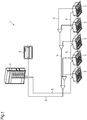
- an air conditioning system 1 includes an outdoor unit 2, which is arranged outdoors, and indoor units 3, which are arranged indoors.
- Fig. 1 shows five indoor units 3.
- the air conditioning system 1 is arranged in, for example, a building such as an office building or a rented building.
- the outdoor unit 2 is connected to the indoor units 3 by refrigerant pipe 5.
- the outdoor unit 2 is connected to the indoor units 3 by an air conditioning communication line 6.
- the air conditioning system 1 of the present embodiment further includes a system management device 4, which is connected to the outdoor unit 2 by the air conditioning communication line 6.
- the system management device 4 for example, receives instructions from a user who manages the building such as the office building or the rented building and centrally manages the indoor units 3.
- the configuration of the air conditioning system may be changed.
- one or more indoor units 3 may be connected to the outdoor unit 2.
- the air conditioning system may include multiple outdoor units 2.
- the air conditioning system may include multiple outdoor units 2, and one or more indoor units 3 may be connected to each outdoor unit 2.
- the system management device 4 may be omitted.
- the air conditioning system 1 it is desired that the controllability of the outdoor unit 2 and the indoor unit 3 be improved. For example, it is required that the outdoor unit 2 and the indoor unit 3 be finely controlled regarding the changes in a setting temperature and the variations in temperature such as room temperature.
- the air conditioning system is configured to execute high-speed communication between the outdoor unit 2 and the indoor units 3.
- the outdoor unit 2 includes, for example, a controller 11, a compressor 12, a fan 14, a compressor inverter 13, a fan inverter 15, a heat exchanger, and various types of valves.
- the compressor 12 is, for example, a positive-displacement compressor such as scroll type compressor or screw type compressor.
- the compressor 12 draws refrigerant in, compresses the refrigerant, and then discharges the refrigerant.
- the compressor 12 includes a motor serving as a drive source.
- the compressor inverter 13 includes a switching element used to drive the motor of the compressor 12.
- the switching element is, for example, an insulated gate bipolar transistor (IGBT).
- the controller 11 executes ON/OFF control for the switching element at a predetermined carrier frequency (for example, 6 kHz). The ON/OFF of the switching element drives the compressor 12.
- the fan 14 is an air blower system that generates air flow that flows into the outdoor unit 2, passes through the outdoor heat exchanger, and then flows out of the outdoor unit 2.
- the fan 14 includes a motor serving as a drive source.
- the fan inverter 15 includes a switching element used to drive the motor of the fan 14.
- the switching element is, for example, an IGBT.
- the controller 11 executes ON/OFF control for the switching element of the fan inverter 15. The ON/OFF of the switching element drives the fan 14.
- the controller 11 is configured as, for example, a control board on which a microcomputer or the like is implemented.
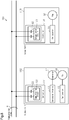
- the controller 11 includes a communication circuit 21, a coupling capacitor 22, and a noise-cut transformer 23.
- the communication circuit 21 communicates with a communication circuit 41 of the indoor unit 3.
- the communication circuit 21 is connected to the air conditioning communication line 6 via the coupling capacitor 22 and the noise-cut transformer 23.
- the communication circuit 21 outputs, to the air conditioning communication line 6 via the coupling capacitor 22 and the noise-cut transformer 23, a communication signal used to transmit operation data.
- the communication circuit 21 generates a signal used for communication through, for example, orthogonal frequency-division multiplexing (OFDM).
- OFDM orthogonal frequency-division multiplexing
- the communication circuit 21 receives operation data from a communication signal that is input from the air conditioning communication line 6 via the noise-cut transformer 23 and the coupling capacitor 22.
- the "operation data” includes, for example, an operating/stopping instruction that is sent from a remote controller or the like and includes temperature information that is obtained by a temperature sensor. Using such operation data, the controller 11 controls the operation frequency of the compressor 12, the opening/closing and switching of various valves, and the like.
- the indoor unit 3 includes, for example, a controller 31, a fan 32, a fan inverter 33, a heat exchanger, and an expansion valve.
- the fan 32 is an air blower system that generates air flow that flows into the outdoor unit 3, passes through the heat exchanger, and then flows out of the outdoor unit 3.
- the fan 32 includes a motor serving as a drive source.
- the fan inverter 33 includes a switching element used to drive the motor of the fan 32.
- the switching element is, for example, an IGBT.
- the controller 31 executes ON/OFF control for the switching element of the fan inverter 33 and adjusts the rotation speed of the fan 32 to control the flow rate of air flow that is generated.
- the controller 31 is configured as, for example, a control board on which a microcomputer or the like is implemented.
- the controller 31 includes a communication circuit 41, a coupling capacitor 42, and a noise-cut transformer 43.
- the communication circuit 41 communicates with the communication circuit 21 of the outdoor unit 2.
- the communication circuit 41 is connected to the air conditioning communication line 6 via the coupling capacitor 42 and the noise-cut transformer 43.
- the communication circuit 41 outputs, to the air conditioning communication line 6 via the coupling capacitor 42 and the noise-cut transformer 43, a communication signal used to transmit operation data. Further, the communication circuit 41 receives operation data from a communication signal that is input from the air conditioning communication line 6 via the noise-cut transformer 43 and the coupling capacitor 42.
- the communication circuit 21 of the outdoor unit 2 is connected to the air conditioning communication line 6 via the coupling capacitor 22 and the noise-cut transformer 23.
- the coupling capacitor 22 and the noise-cut transformer 23 are set in correspondence with the noise superimposed on the communication signal.
- Fig. 3 shows an outdoor unit 202 and an indoor unit 203, which configure an air conditioning system 201 according to a modification.
- the components that are the same as those of the outdoor unit 2 and the indoor unit 3 of the embodiment shown in Fig. 2 will be described with the same reference numerals.
- the outdoor unit 202 of the comparative example includes a controller 211, the compressor 12, the compressor inverter 13, the fan 14, and the fan inverter 15.
- the controller 211 includes the communication circuit 21 and the coupling capacitor 22, and the communication circuit 21 is connected to the air conditioning communication line 6 via the coupling capacitor 22.
- the indoor unit 203 includes a controller 231, the fan 32, and the fan inverter 33.
- the controller 231 includes the communication circuit 41 and the coupling capacitor 42, and the communication circuit 41 is connected to the air conditioning communication line 6 via the coupling capacitor 42.
- the outdoor unit 202 includes the compressor inverter 13, which drives the compressor 12.
- the compressor inverter 13 includes a switching element used to drive the compressor 12.
- the ON/OFF of the switching element drives the compressor 12.
- the noise corresponding to the ON/OFF of the switching element is generated.
- the ON/OFF of the switching element is indicated by an ON/OFF waveform surrounded by a broken circle.
- Noise Nx (common mode noise) based on the ON/OFF of the switching element enters the air conditioning communication line 6 via a parasitic capacitance 251 and is superimposed on the communication signal transmitted via the air conditioning communication line 6.
- Fig. 4 shows an example of the waveform of a communication signal Sa.
- Fig. 5 shows an example of the waveform of the communication signal Sa on which noise Nx is superimposed.
- baseband transmission is employed to encode data and transmit/receive the data
- ringing that results from the influence of a switching noise of the compressor inverter 13 is superimposed on the communication signal Sa as noise Nx as shown in Fig. 5 .
- noise Nx generated in the outdoor unit 202 is superimposed on a communication signal Sx, which is transmitted by the air conditioning communication line 6.
- the coupling capacitor 22, which is connected between the communication circuit 21 and the air conditioning communication line 6, includes a characteristic for passing a high-frequency component. Accordingly, the communication signal Sx including noise Nx is received by the communication circuit 21 of the outdoor unit 2. Noise Nx entering in this manner is a factor that changes the waveform of the communication signal Sx depending on the frequency and level of noise Nx to cause a communication abnormality.
- the communication signal including noise is received by the communication circuit 41 via the coupling capacitor 42, and the noise included in the received signal is a factor that causes a communication abnormality.
- a communication signal S1 which is transmitted and received to and from the outdoor unit 2 and the indoor unit 3 of the air conditioning system of the present embodiment, includes frequency components from frequency f1 to frequency f2 in a predetermined modulation method.
- the modulation method is, for example, an orthogonal frequency-division multiplexing (OFDM).
- Frequency f1 is, for example, 2 MHz.
- Frequency f2 is, for example, 30 MHz.
- Frequency f2 may be greater than or equal to 30 MHz.
- Noise Nx generated by driving the compressor 12 includes frequency components within a range from frequency f3 to frequency f4, which are higher than frequency f1.
- noise Nx generated by the compressor 12 includes frequency components around 5 MHz.
- the noise generated in this manner includes frequency components with a predetermined frequency width (for example, 3 MHz) and the center frequency of the predetermined frequency width changes in correspondence with the state (installed state, operating state) of the air conditioning system 1.
- frequency f3 is 3 MHz and frequency f4 is 6 MHz in an example of the installation and frequency f3 is 5 MHz and frequency f4 is 8 MHz in another example of the installation.
- the frequency components of noise change depending on the configuration with a frequency width of 3 MHz, and have a lower limit value of, for example, 3 MHz and have an upper limit value of 10 MHz.
- the widths of the frequency components included in noise may differ between devices.
- the inventors of the present invention have found out that the frequency band is 1 to 5 MHz.
- the inventors of the present invention have also found out that the generation source of noise is not limited to the above-described compressor inverter 13 and the noise that affects communication may be generated from, for example, the fan inverter 15.
- the inventors of the present invention have found out that the frequency band of noise generated by driving the fan inverter 15 is 15 to 20 MHz.
- the air conditioning system 1 of the present embodiment includes the outdoor unit 2 and the indoor units 3, which are connected to the outdoor unit 2 by the refrigerant pipe 5 and the air conditioning communication line 6.
- the controller 11 of the outdoor unit 2 includes the coupling capacitor 22 and the noise-cut transformer 23, which are located between the communication circuit 21 and the air conditioning communication line 6.
- the coupling capacitor 22 passes a high-frequency component
- the noise-cut transformer 23 passes a low-frequency component.
- the frequency characteristics of the noise-cut transformer 23 can be adjusted by changing how to wind coils and changing the material of the core.
- a frequency component within a range corresponding to noise in the frequency components of the communication signal can be adjusted.
- the width of the frequency component to be adjusted be, for example, 1 MHz to 5 MHz.
- the frequency component to be adjusted be set within a predetermined range (for example, 3 to 10 MHz) in correspondence with the noise in which the frequency within the predetermined range is generated in the outdoor unit 2.
- the lower limit value be set to, for example, 3 MHz and the upper limit value be set to, for example, 10 MHz.
- the coupling capacitor 22 and the noise-cut transformer 23 are used to adjust the level of the frequency band (f3 to f4) corresponding to noise Nx superimposed on the communication signal S1 received from the conditioning communication line 6, thereby limiting the occurrence of a communication abnormality.
- Fig. 6 shows the frequency components of the communication signal S1 that have passed through the coupling capacitor 22 and the noise-cut transformer 23.
- the communication signal S1 includes frequency components from frequency f1 to frequency f3 and frequency components from frequency f4 to frequency f2, and frequency components from frequency f3 to frequency f4 shown in Fig. 7 are adjusted. That is, the coupling capacitor 22 and the noise-cut transformer 23 configure a signal adjustment mechanism that adjusts a predetermined frequency component of the communication signal S1.
- the signal adjustment mechanism is used to adjust the signal level of the predetermined frequency component in the communication signal S1, thereby limiting the occurrence of a communication abnormality resulting from the entry of noise Nx.
- the controller 31 of the indoor unit 3 includes the coupling capacitor 42 and the noise-cut transformer 43, which are located between the communication circuit 41 and the air conditioning communication line 6.
- the coupling capacitor 42 passes a high-frequency component
- the noise-cut transformer 43 passes a low-frequency component. Accordingly, in the same manner as the outdoor unit 2, in the indoor unit 3, the frequency characteristics of the coupling capacitor 42 and the noise-cut transformer 43 are adjusted to reduce the level of the frequency component corresponding to the noise generated in the outdoor unit 2.
- the coupling capacitor 42 and the noise-cut transformer 43 configure a signal adjustment mechanism that adjusts a predetermined frequency component of the communication signal S1. Therefore, in the indoor unit 3, the occurrence of a communication abnormality is limited.
- the present embodiment has the following advantages.
- an air conditioning system 101 includes an outdoor unit 102 and an indoor unit 103.
- the outdoor unit 102 and the indoor unit 103 are connected to each other by the conditioning communication line 6 in a communicable manner.
- Fig. 8 shows one outdoor unit 102 and one indoor unit 103
- multiple indoor units 103 may be connected in the same manner as the first embodiment.
- multiple outdoor units 102 and multiple indoor units 103 may be connected to each other.
- the system management device 4 shown in Fig. 1 may be connected.
- the outdoor unit 102 includes, for example, a controller 111, the compressor 12, the fan 14, the compressor inverter 13, the fan inverter 15, a heat exchanger, and various types of valves.
- the controller 111 is configured as, for example, a control board on which a microcomputer or the like is implemented.
- the controller 111 includes a communication circuit 121 and the coupling capacitor 22.
- the communication circuit 121 communicates with a communication circuit 141 of the indoor unit 103.
- the communication circuit 121 is connected to the air conditioning communication line 6 via the coupling capacitor 22.
- the indoor unit 103 includes, for example, a controller 131, the fan 32, the fan inverter 33, a heat exchanger, and an expansion valve.
- the controller 131 is configured as, for example, a control board on which a microcomputer or the like is implemented.
- the controller 131 includes a communication circuit 141 and the coupling capacitor 42.
- the communication circuit 141 communicates with the communication circuit 121 of the outdoor unit 102.
- the communication circuit 141 is connected to the air conditioning communication line 6 via the coupling capacitor 42.
- Fig. 9 shows a block diagram of the communication circuit 121 of the outdoor unit 102 of the present embodiment.
- the communication circuit 141 of the indoor unit 103 has the same configuration as the communication circuit 121 of the outdoor unit 102.
- the communication circuit 121 includes a communication controller 151, an error correction encoder 152, a tone map creator 153, an inverse wavelet converter 154, a transmitter 155, a receiver 156, a wavelet converter 157, a transmission path estimation equalizer 158, and an error corrector 159.
- the communication controller 151 is, for example, a media access control (MAC) unit.
- the transmitter 155 includes, for example, a digital-to-analog converter (DAC) and an amplifier (AMP).
- the receiver 156 includes, for example, an amplifier (PGA) and an analog-to-digital converter (ADC).
- Operation data is converted into a communication signal by the communication controller 151, the error correction encoder 152, the tone map creator 153, the inverse wavelet converter 154, and the transmitter 155, and output to the air conditioning communication line 6 shown in Fig. 8 .
- the conditioning communication line 6 transmitted by the air conditioning communication line 6 is received as operation data via the receiver 156, the wavelet converter 157, the transmission path estimation equalizer 158, the error corrector 159, and the communication controller 151.
- the tone map creator 153 uses creation information, which is stored in a memory 160, to create a tone map of a predetermined carrier frequency (carrier number).
- the carrier frequency is, for example, 2 MHz to 30 MHz.
- the memory 160 stores, as the creation information, the frequency of the noise generated in the outdoor unit 102 and switch information, which indicates whether the tone map needs to be created.
- the frequencies of the noise are frequencies f3 and f4 of the frequency components included in the noise described in the first embodiment.
- the switch information is information (flag) that indicates whether to adjust a signal component in the frequency of noise.
- the tone map creator 153 When the flag is set (for example, 1), the tone map creator 153 creates a tone map that does not include the information of a frequency component (frequency f3 to frequency f4) of the set noise in the carrier frequencies used for communication. When the flag is not set (for example, 0), the tone map creator 153 creates a tone map that includes all the information of the carrier frequencies.
- the tone map that includes the frequency components of noise and the tone map that does not include the frequency components of noise can be switched by setting and clearing the flag in correspondence with the state of the air conditioning system 101.
- the amount of noise generation and the degree of noise entry differ depending on an installed state of the outdoor unit 102 and a laid state of the air conditioning communication line 6.
- noise Nx generated in the outdoor unit 102 is superimposed on the communication signal transmitted to the indoor unit 103 via the air conditioning communication line 6.
- the communication signal including noise is received by the communication circuit 141, and the noise included in the received signal may result in a communication abnormality.
- the refrigerant pipe 5 between the outdoor unit 102 and the indoor unit 103 is long and the air conditioning communication line 6 is accordingly long.
- the longer the length of the air conditioning communication line 6 between the outdoor unit 102 and the indoor unit 103 the smaller the high-frequency component included in the communication signal becomes and the smaller the S/N ratio of the communication signal becomes.
- each indoor unit 103 In multiple indoor units 103 connected to the air conditioning communication line 6, the influence of noise on each indoor unit 103 may differ depending on the length of the air conditioning communication line 6 from the outdoor unit 102 to each indoor unit 103 and depending on the installed state of each indoor unit 103. Accordingly, in each indoor unit 103, by using the flag, the ON/OFF of the adjustment of a frequency component used for communication can be easily set.
- the present embodiment has the following advantages.
- a frequency component used for communication simply needs to be adjusted.
- a communication signal may be generated using a modulation method such as OFDM.
- frequency f3 may be stored in the memory 160 and the value obtained by adding a predetermined value (for example, 3 MHz) to frequency f3 may be calculated so that the information of frequency f3 to the calculated value is not generated in the tone map creator 153.
- frequency f4 may be stored in the memory 160 and the value obtained by subtracting the predetermined value (for example, 3 MHz) from frequency f4 may be calculated so that the information of frequency f4 to the calculated value is not generated in the tone map creator 153.
- center frequency of a frequency band to be adjusted may be stored in the memory 160 to adjust the signal level at a predetermined frequency band from the center frequency.
- center frequency and the frequency width that is to be adjusted may be stored in the memory 160 to adjust the signal level.
- the second embodiment may be configured to receive noise and compare the level of the noise with a threshold value so that the flag is set and cleared in correspondence with the level of the noise.
- a channel that bypasses the noise-cut transformers 23 and 43 and a switch in the channel may be provided so that the adjustment of a frequency component used for communication is switched between activation and deactivation by turning the switch on and off during installation.
- the switch may be turned on and off using the result of the level of determination of an instruction signal or noise during operation.
- the signal level of a frequency band corresponding to noise may be adjusted in at least one of the outdoor unit and the indoor unit.
Landscapes
- Engineering & Computer Science (AREA)
- Chemical & Material Sciences (AREA)
- Combustion & Propulsion (AREA)
- Mechanical Engineering (AREA)
- General Engineering & Computer Science (AREA)
- Computer Networks & Wireless Communication (AREA)
- Signal Processing (AREA)
- Human Computer Interaction (AREA)
- Air Conditioning Control Device (AREA)
- Central Air Conditioning (AREA)
- Sorption Type Refrigeration Machines (AREA)
Abstract
Description
- The present invention relates to an air conditioning system.
- A typical air conditioning system connects an outdoor unit and indoor units to each other by an air conditioning communication line. The outdoor unit includes a compressor and an inverter circuit that drives the compressor. Each of the indoor units includes a control circuit that controls the indoor unit. For example, the noise in the inverter circuit affects a communication signal between the outdoor unit and the indoor unit.
- Patent Document 1: Japanese Patent No.
4336142 - To improve the controllability of the outdoor unit and the indoor unit, it is preferred that the communication speed in the air conditioning communication line be increased. However, since the influence of the noise becomes larger when the communication line is increased as described above, it is difficult to increase the communication speed in the air conditioning communication line and reduce the influence of noise at the same time.
- The objective of the present invention is to provide an air conditioning system capable of reducing the influence of noise on high-speed communication.
- An air conditioning system according to a first aspect includes an outdoor unit (2) including an inverter circuit (13), an indoor unit (3) connected to the outdoor unit (2) in a communicable manner, and a signal adjustment mechanism (22, 23, 42, 43, 153) for communication between the outdoor unit (2) and the indoor unit (3). For a communication signal, the signal adjustment mechanism adjusts the level of a desired frequency band or adjusts a frequency used for communication.
- In the air conditioning system of the first aspect, by adjusting the level of a signal component of a frequency corresponding to the inverter circuit in the frequency components of a communication signal or by adjusting the communication signal such that the predetermined frequency band is not used, the influence of noise is reduced to enable high-speed communication,
- In an air conditioning system according to a second aspect, the signal adjustment mechanism adjusts a signal level included in a predetermined frequency width.
- In the air conditioning system of the second aspect, by setting a frequency width with which the level is adjusted, high-speed communication is enabled using a high-frequency signal component.
- In an air conditioning system according to a third aspect, the signal adjustment mechanism generates a communication signal that does not include a predetermined frequency width.
- In the air conditioning system of the third aspect, by setting a predetermined frequency width in correspondence with entering noise, a communication signal that does not include a frequency width including noise enables high-speed communication without the influence of noise.
- In an air conditioning system according to a fourth aspect, the signal adjustment mechanism is activated at a predetermined frequency width. The activation of the signal adjustment mechanism is to adjust the level of a communication signal, and the deactivation of the signal adjustment mechanism is not to adjust the level of a communication signal.
- In the air conditioning system of the fourth aspect, by limiting a frequency to be adjusted to a predetermined frequency width, the distortion (deformation) of a signal waveform is limited to enable high-speed communication.
- In an air conditioning system according to a fifth aspect, a center frequency of the frequency width with which the signal adjustment mechanism is activated is variable.
- In the air conditioning system of the fifth aspect, the adjustment of a signal corresponding to the state of a communication channel (the state of the outdoor unit (2)) is enabled.
- An air conditioning system according to a sixth aspect includes a switching mechanism (153, 160) that switches the signal adjustment mechanism between activation and deactivation.
- In the air conditioning system of the sixth aspect, a decrease in the communication quality (signal waveform) is limited by switching the signal adjustment mechanism between activation and deactivation in correspondence with the installed state (communication distance, noise level).
- In an air conditioning system according to a seventh aspect, the signal adjustment mechanism is provided on at least one of the outdoor unit (2) or the indoor unit (3).
- In an air conditioning system according to an eighth aspect, the signal adjustment mechanism includes a noise-cut transformer (23, 43) connected with an air conditioning signal line (6).
-
-
Fig. 1 is a schematic diagram of an air conditioning system according to a first embodiment. -
Fig. 2 is a schematic block diagram of the outdoor unit and the indoor unit of the first embodiment. -
Fig. 3 is a diagram illustrating the entry of noise in the outdoor unit and the indoor unit. -
Fig. 4 is a waveform chart of a communication signal. -
Fig. 5 is a waveform chart of the communication signal that includes noise. -
Fig. 6 is a diagram illustrating the frequency components of the communication signal in high-speed communication. -
Fig. 7 is a diagram illustrating the frequency components of the communication signal and noise. -
Fig. 8 is a schematic block diagram of an air conditioning system (outdoor unit and indoor unit) according to a second embodiment. -
Fig. 9 is a block diagram of the communication circuit of the second embodiment. - Air conditioning systems according to embodiments of the present invention will now be described. The scope of the present invention is defined not by the detailed description, but by the claims and their equivalents, and all variations within the scope of the claims and their equivalents are to be construed as being included in the disclosure.
- A first embodiment will now be described.
- As shown in
Fig. 1 , anair conditioning system 1 includes an outdoor unit 2, which is arranged outdoors, andindoor units 3, which are arranged indoors.Fig. 1 shows fiveindoor units 3. Theair conditioning system 1 is arranged in, for example, a building such as an office building or a rented building. The outdoor unit 2 is connected to theindoor units 3 byrefrigerant pipe 5. In addition, the outdoor unit 2 is connected to theindoor units 3 by an airconditioning communication line 6. Theair conditioning system 1 of the present embodiment further includes asystem management device 4, which is connected to the outdoor unit 2 by the airconditioning communication line 6. Thesystem management device 4, for example, receives instructions from a user who manages the building such as the office building or the rented building and centrally manages theindoor units 3. - The configuration of the air conditioning system may be changed. For example, one or more
indoor units 3 may be connected to the outdoor unit 2. Alternatively, the air conditioning system may include multiple outdoor units 2. As another option, the air conditioning system may include multiple outdoor units 2, and one or moreindoor units 3 may be connected to each outdoor unit 2. As an alternative, thesystem management device 4 may be omitted. - In the
air conditioning system 1, it is desired that the controllability of the outdoor unit 2 and theindoor unit 3 be improved. For example, it is required that the outdoor unit 2 and theindoor unit 3 be finely controlled regarding the changes in a setting temperature and the variations in temperature such as room temperature. Thus, the air conditioning system is configured to execute high-speed communication between the outdoor unit 2 and theindoor units 3. - As shown in
Fig. 2 , the outdoor unit 2 includes, for example, a controller 11, acompressor 12, afan 14, acompressor inverter 13, afan inverter 15, a heat exchanger, and various types of valves. - The
compressor 12 is, for example, a positive-displacement compressor such as scroll type compressor or screw type compressor. Thecompressor 12 draws refrigerant in, compresses the refrigerant, and then discharges the refrigerant. Thecompressor 12 includes a motor serving as a drive source. Thecompressor inverter 13 includes a switching element used to drive the motor of thecompressor 12. The switching element is, for example, an insulated gate bipolar transistor (IGBT). The controller 11 executes ON/OFF control for the switching element at a predetermined carrier frequency (for example, 6 kHz). The ON/OFF of the switching element drives thecompressor 12. - The
fan 14 is an air blower system that generates air flow that flows into the outdoor unit 2, passes through the outdoor heat exchanger, and then flows out of the outdoor unit 2. Thefan 14 includes a motor serving as a drive source. Thefan inverter 15 includes a switching element used to drive the motor of thefan 14. The switching element is, for example, an IGBT. The controller 11 executes ON/OFF control for the switching element of thefan inverter 15. The ON/OFF of the switching element drives thefan 14. - The controller 11 is configured as, for example, a control board on which a microcomputer or the like is implemented. The controller 11 includes a
communication circuit 21, acoupling capacitor 22, and a noise-cut transformer 23. Thecommunication circuit 21 communicates with acommunication circuit 41 of theindoor unit 3. Thecommunication circuit 21 is connected to the airconditioning communication line 6 via thecoupling capacitor 22 and the noise-cut transformer 23. - The
communication circuit 21 outputs, to the airconditioning communication line 6 via thecoupling capacitor 22 and the noise-cut transformer 23, a communication signal used to transmit operation data. Thecommunication circuit 21 generates a signal used for communication through, for example, orthogonal frequency-division multiplexing (OFDM). Further, thecommunication circuit 21 receives operation data from a communication signal that is input from the airconditioning communication line 6 via the noise-cut transformer 23 and thecoupling capacitor 22. The "operation data" includes, for example, an operating/stopping instruction that is sent from a remote controller or the like and includes temperature information that is obtained by a temperature sensor. Using such operation data, the controller 11 controls the operation frequency of thecompressor 12, the opening/closing and switching of various valves, and the like. - The
indoor unit 3 includes, for example, acontroller 31, afan 32, afan inverter 33, a heat exchanger, and an expansion valve. Thefan 32 is an air blower system that generates air flow that flows into theoutdoor unit 3, passes through the heat exchanger, and then flows out of theoutdoor unit 3. Thefan 32 includes a motor serving as a drive source. Thefan inverter 33 includes a switching element used to drive the motor of thefan 32. The switching element is, for example, an IGBT. Thecontroller 31 executes ON/OFF control for the switching element of thefan inverter 33 and adjusts the rotation speed of thefan 32 to control the flow rate of air flow that is generated. - The
controller 31 is configured as, for example, a control board on which a microcomputer or the like is implemented. Thecontroller 31 includes acommunication circuit 41, acoupling capacitor 42, and a noise-cut transformer 43. Thecommunication circuit 41 communicates with thecommunication circuit 21 of the outdoor unit 2. Thecommunication circuit 41 is connected to the airconditioning communication line 6 via thecoupling capacitor 42 and the noise-cut transformer 43. Thecommunication circuit 41 outputs, to the airconditioning communication line 6 via thecoupling capacitor 42 and the noise-cut transformer 43, a communication signal used to transmit operation data. Further, thecommunication circuit 41 receives operation data from a communication signal that is input from the airconditioning communication line 6 via the noise-cut transformer 43 and thecoupling capacitor 42. - As described above, the
communication circuit 21 of the outdoor unit 2 is connected to the airconditioning communication line 6 via thecoupling capacitor 22 and the noise-cut transformer 23. Thecoupling capacitor 22 and the noise-cut transformer 23 are set in correspondence with the noise superimposed on the communication signal. - The generation and superimposition of noise will now be described.
-
Fig. 3 shows anoutdoor unit 202 and anindoor unit 203, which configure anair conditioning system 201 according to a modification. The components that are the same as those of the outdoor unit 2 and theindoor unit 3 of the embodiment shown inFig. 2 will be described with the same reference numerals. - The
outdoor unit 202 of the comparative example includes acontroller 211, thecompressor 12, thecompressor inverter 13, thefan 14, and thefan inverter 15. Thecontroller 211 includes thecommunication circuit 21 and thecoupling capacitor 22, and thecommunication circuit 21 is connected to the airconditioning communication line 6 via thecoupling capacitor 22. - The
indoor unit 203 includes acontroller 231, thefan 32, and thefan inverter 33. Thecontroller 231 includes thecommunication circuit 41 and thecoupling capacitor 42, and thecommunication circuit 41 is connected to the airconditioning communication line 6 via thecoupling capacitor 42. - The
outdoor unit 202 includes thecompressor inverter 13, which drives thecompressor 12. Thecompressor inverter 13 includes a switching element used to drive thecompressor 12. The ON/OFF of the switching element drives thecompressor 12. The noise corresponding to the ON/OFF of the switching element is generated. InFig. 3 , the ON/OFF of the switching element is indicated by an ON/OFF waveform surrounded by a broken circle. Noise Nx (common mode noise) based on the ON/OFF of the switching element enters the airconditioning communication line 6 via aparasitic capacitance 251 and is superimposed on the communication signal transmitted via the airconditioning communication line 6. -
Fig. 4 shows an example of the waveform of a communication signal Sa.Fig. 5 shows an example of the waveform of the communication signal Sa on which noise Nx is superimposed. In the air conditioning system, when baseband transmission is employed to encode data and transmit/receive the data, ringing that results from the influence of a switching noise of thecompressor inverter 13 is superimposed on the communication signal Sa as noise Nx as shown inFig. 5 . - As shown in
Fig. 3 , noise Nx generated in theoutdoor unit 202 is superimposed on a communication signal Sx, which is transmitted by the airconditioning communication line 6. Thecoupling capacitor 22, which is connected between thecommunication circuit 21 and the airconditioning communication line 6, includes a characteristic for passing a high-frequency component. Accordingly, the communication signal Sx including noise Nx is received by thecommunication circuit 21 of the outdoor unit 2. Noise Nx entering in this manner is a factor that changes the waveform of the communication signal Sx depending on the frequency and level of noise Nx to cause a communication abnormality. In theindoor unit 203, in the same manner as theoutdoor unit 202, the communication signal including noise is received by thecommunication circuit 41 via thecoupling capacitor 42, and the noise included in the received signal is a factor that causes a communication abnormality. - As shown in
Fig. 7 , a communication signal S1, which is transmitted and received to and from the outdoor unit 2 and theindoor unit 3 of the air conditioning system of the present embodiment, includes frequency components from frequency f1 to frequency f2 in a predetermined modulation method. The modulation method is, for example, an orthogonal frequency-division multiplexing (OFDM). Frequency f1 is, for example, 2 MHz. Frequency f2 is, for example, 30 MHz. Frequency f2 may be greater than or equal to 30 MHz. Noise Nx generated by driving thecompressor 12 includes frequency components within a range from frequency f3 to frequency f4, which are higher than frequency f1. The inventors of the present invention have found out that when thecompressor 12 is driven at a predetermined carrier frequency (for example, 6 kHz) in theair conditioning system 1, noise Nx generated by thecompressor 12 includes frequency components around 5 MHz. The inventors of the present invention have also found out that the noise generated in this manner includes frequency components with a predetermined frequency width (for example, 3 MHz) and the center frequency of the predetermined frequency width changes in correspondence with the state (installed state, operating state) of theair conditioning system 1. Regarding the frequency components of noise, frequency f3 is 3 MHz and frequency f4 is 6 MHz in an example of the installation and frequency f3 is 5 MHz and frequency f4 is 8 MHz in another example of the installation. That is, the frequency components of noise change depending on the configuration with a frequency width of 3 MHz, and have a lower limit value of, for example, 3 MHz and have an upper limit value of 10 MHz. The widths of the frequency components included in noise (i.e., the frequency band of noise) may differ between devices. The inventors of the present invention have found out that the frequency band is 1 to 5 MHz. The inventors of the present invention have also found out that the generation source of noise is not limited to the above-describedcompressor inverter 13 and the noise that affects communication may be generated from, for example, thefan inverter 15. In addition, the inventors of the present invention have found out that the frequency band of noise generated by driving thefan inverter 15 is 15 to 20 MHz. - The
air conditioning system 1 of the present embodiment includes the outdoor unit 2 and theindoor units 3, which are connected to the outdoor unit 2 by therefrigerant pipe 5 and the airconditioning communication line 6. - As shown in
Fig. 2 , the controller 11 of the outdoor unit 2 includes thecoupling capacitor 22 and the noise-cut transformer 23, which are located between thecommunication circuit 21 and the airconditioning communication line 6. Among the frequency components included in the communication signal, thecoupling capacitor 22 passes a high-frequency component, and the noise-cut transformer 23 passes a low-frequency component. - The frequency characteristics of the noise-
cut transformer 23 can be adjusted by changing how to wind coils and changing the material of the core. Thus, a frequency component within a range corresponding to noise in the frequency components of the communication signal can be adjusted. For example, when the frequency component corresponds to the noise generated by the above-describedcompressor inverter 13, it is preferred that the width of the frequency component to be adjusted be, for example, 1 MHz to 5 MHz. It is preferred that the frequency component to be adjusted be set within a predetermined range (for example, 3 to 10 MHz) in correspondence with the noise in which the frequency within the predetermined range is generated in the outdoor unit 2. In this case, it is preferred that the lower limit value be set to, for example, 3 MHz and the upper limit value be set to, for example, 10 MHz. In this manner, thecoupling capacitor 22 and the noise-cut transformer 23 are used to adjust the level of the frequency band (f3 to f4) corresponding to noise Nx superimposed on the communication signal S1 received from theconditioning communication line 6, thereby limiting the occurrence of a communication abnormality. -
Fig. 6 shows the frequency components of the communication signal S1 that have passed through thecoupling capacitor 22 and the noise-cut transformer 23. The communication signal S1 includes frequency components from frequency f1 to frequency f3 and frequency components from frequency f4 to frequency f2, and frequency components from frequency f3 to frequency f4 shown inFig. 7 are adjusted. That is, thecoupling capacitor 22 and the noise-cut transformer 23 configure a signal adjustment mechanism that adjusts a predetermined frequency component of the communication signal S1. The signal adjustment mechanism is used to adjust the signal level of the predetermined frequency component in the communication signal S1, thereby limiting the occurrence of a communication abnormality resulting from the entry of noise Nx. - As shown in
Fig. 2 , thecontroller 31 of theindoor unit 3 includes thecoupling capacitor 42 and the noise-cut transformer 43, which are located between thecommunication circuit 41 and the airconditioning communication line 6. Among the frequency components included in the communication signal, thecoupling capacitor 42 passes a high-frequency component, and the noise-cut transformer 43 passes a low-frequency component. Accordingly, in the same manner as the outdoor unit 2, in theindoor unit 3, the frequency characteristics of thecoupling capacitor 42 and the noise-cut transformer 43 are adjusted to reduce the level of the frequency component corresponding to the noise generated in the outdoor unit 2. Thecoupling capacitor 42 and the noise-cut transformer 43 configure a signal adjustment mechanism that adjusts a predetermined frequency component of the communication signal S1. Therefore, in theindoor unit 3, the occurrence of a communication abnormality is limited. - As described above, the present embodiment has the following advantages.
- (1-1) The controller 11 of the outdoor unit 2 includes the
coupling capacitor 22 and the noise-cut transformer 23, which are located between thecommunication circuit 21 and the airconditioning communication line 6. Thecoupling capacitor 22 and the noise-cut transformer 23 configure a signal adjustment mechanism that adjusts a predetermined frequency component of the communication signal S1. Thus, the level of the predetermined frequency band is adjusted using the noise-cut transformer 23 to limit the influence of noise Nx superimposed on the communication signal S1 received from the airconditioning communication line 6 in the frequency band. As a result, the occurrence of a communication abnormality is limited. - (1-2) In correspondence with the frequency component of noise Nx, as the range of the frequency component to be adjusted is narrower, the
communication circuit 21 receives the communication signal S1 in a waveform that is closer to the original pulse waveform. Thus, in the outdoor unit 2, a quality communication signal S1 is gained. This limits the occurrence of a communication abnormality. - (1-3) In the
indoor unit 3, the frequency component corresponding to the noise generated in the outdoor unit 2 is adjusted by adjusting the frequency characteristics of thecoupling capacitor 42 and the noise-cut transformer 43. Thecoupling capacitor 42 and the noise-cut transformer 43 configure a signal adjustment mechanism that adjusts a predetermined frequency component of the communication signal S1. Therefore, in theindoor unit 3, the occurrence of a communication abnormality is limited. - A second embodiment will now be described.
- In the present embodiment, the same reference numerals are given to those components that are like or the same as the corresponding components of the first embodiment, and part of or all of the description is omitted.
- As shown in
Fig. 8 , anair conditioning system 101 includes anoutdoor unit 102 and anindoor unit 103. Theoutdoor unit 102 and theindoor unit 103 are connected to each other by theconditioning communication line 6 in a communicable manner. WhileFig. 8 shows oneoutdoor unit 102 and oneindoor unit 103, multipleindoor units 103 may be connected in the same manner as the first embodiment. Alternatively, multipleoutdoor units 102 and multipleindoor units 103 may be connected to each other. In addition, thesystem management device 4 shown inFig. 1 may be connected. - The
outdoor unit 102 includes, for example, acontroller 111, thecompressor 12, thefan 14, thecompressor inverter 13, thefan inverter 15, a heat exchanger, and various types of valves. - The
controller 111 is configured as, for example, a control board on which a microcomputer or the like is implemented. Thecontroller 111 includes acommunication circuit 121 and thecoupling capacitor 22. Thecommunication circuit 121 communicates with acommunication circuit 141 of theindoor unit 103. Thecommunication circuit 121 is connected to the airconditioning communication line 6 via thecoupling capacitor 22. - The
indoor unit 103 includes, for example, acontroller 131, thefan 32, thefan inverter 33, a heat exchanger, and an expansion valve. - The
controller 131 is configured as, for example, a control board on which a microcomputer or the like is implemented. Thecontroller 131 includes acommunication circuit 141 and thecoupling capacitor 42. Thecommunication circuit 141 communicates with thecommunication circuit 121 of theoutdoor unit 102. Thecommunication circuit 141 is connected to the airconditioning communication line 6 via thecoupling capacitor 42. -
Fig. 9 shows a block diagram of thecommunication circuit 121 of theoutdoor unit 102 of the present embodiment. Thecommunication circuit 141 of theindoor unit 103 has the same configuration as thecommunication circuit 121 of theoutdoor unit 102. - The
communication circuit 121 includes acommunication controller 151, anerror correction encoder 152, atone map creator 153, aninverse wavelet converter 154, atransmitter 155, areceiver 156, awavelet converter 157, a transmissionpath estimation equalizer 158, and anerror corrector 159. Thecommunication controller 151 is, for example, a media access control (MAC) unit. Thetransmitter 155 includes, for example, a digital-to-analog converter (DAC) and an amplifier (AMP). Thereceiver 156 includes, for example, an amplifier (PGA) and an analog-to-digital converter (ADC). - Operation data is converted into a communication signal by the
communication controller 151, theerror correction encoder 152, thetone map creator 153, theinverse wavelet converter 154, and thetransmitter 155, and output to the airconditioning communication line 6 shown inFig. 8 . Theconditioning communication line 6 transmitted by the airconditioning communication line 6 is received as operation data via thereceiver 156, thewavelet converter 157, the transmissionpath estimation equalizer 158, theerror corrector 159, and thecommunication controller 151. - The
tone map creator 153 uses creation information, which is stored in amemory 160, to create a tone map of a predetermined carrier frequency (carrier number). The carrier frequency is, for example, 2 MHz to 30 MHz. Thememory 160 stores, as the creation information, the frequency of the noise generated in theoutdoor unit 102 and switch information, which indicates whether the tone map needs to be created. The frequencies of the noise are frequencies f3 and f4 of the frequency components included in the noise described in the first embodiment. The switch information is information (flag) that indicates whether to adjust a signal component in the frequency of noise. When the flag is set (for example, 1), thetone map creator 153 creates a tone map that does not include the information of a frequency component (frequency f3 to frequency f4) of the set noise in the carrier frequencies used for communication. When the flag is not set (for example, 0), thetone map creator 153 creates a tone map that includes all the information of the carrier frequencies. - The use of a tone map that does include a frequency component of noise generates a transmission signal that does not include the frequency component. Thus, since the transmission signal is unaffected by the entry of noise, the occurrence of a communication abnormality is limited.
- In the present embodiment, the tone map that includes the frequency components of noise and the tone map that does not include the frequency components of noise can be switched by setting and clearing the flag in correspondence with the state of the
air conditioning system 101. The amount of noise generation and the degree of noise entry differ depending on an installed state of theoutdoor unit 102 and a laid state of the airconditioning communication line 6. In high-speed communication, it is preferred that all the carrier frequencies be used. Therefore, by clearing the flag in correspondence with the state of noise, a quality transmission signal is generated to enable high-speed communication. Also, by setting the flag, a transmission signal with a reduced influence of noise is generated to enable high-speed communication. - As described in the first embodiment, noise Nx generated in the
outdoor unit 102 is superimposed on the communication signal transmitted to theindoor unit 103 via the airconditioning communication line 6. In theindoor unit 103, in the same manner as theoutdoor unit 102, the communication signal including noise is received by thecommunication circuit 141, and the noise included in the received signal may result in a communication abnormality. - For example, in the
air conditioning system 101, which is arranged in a building such as an office building, therefrigerant pipe 5 between theoutdoor unit 102 and theindoor unit 103 is long and the airconditioning communication line 6 is accordingly long. The longer the length of the airconditioning communication line 6 between theoutdoor unit 102 and theindoor unit 103, the smaller the high-frequency component included in the communication signal becomes and the smaller the S/N ratio of the communication signal becomes. - In multiple
indoor units 103 connected to the airconditioning communication line 6, the influence of noise on eachindoor unit 103 may differ depending on the length of the airconditioning communication line 6 from theoutdoor unit 102 to eachindoor unit 103 and depending on the installed state of eachindoor unit 103. Accordingly, in eachindoor unit 103, by using the flag, the ON/OFF of the adjustment of a frequency component used for communication can be easily set. - As described above, the present embodiment has the following advantages.
- (2-1) The tone map that includes the frequency components of noise and the tone map that does not include the frequency components of noise can be switched by setting and clearing the flag in correspondence with the state of the
air conditioning system 101. The amount of noise generation and the degree of noise entry differ depending on the installed state of theoutdoor unit 102 and the laid state of the airconditioning communication line 6. In high-speed communication, it is preferred that all the carrier frequencies be used. Therefore, by clearing the flag in correspondence with the state of noise, a quality transmission signal is generated to enable high-speed communication. Also, by setting the flag, a transmission signal with a reduced influence of noise is generated to enable high-speed communication. - (2-2) In multiple
indoor units 103 connected to the airconditioning communication line 6, the influence of noise on eachindoor unit 103 may differ depending on the length of the airconditioning communication line 6 from theoutdoor unit 102 to eachindoor unit 103 and depending on the installed state of eachindoor unit 103. Accordingly, in eachindoor unit 103, by using the flag, the ON/OFF of the adjustment of a frequency component used for communication can be easily set. - Each of the above-described embodiments may be modified as follows.
- In the second embodiment, a frequency component used for communication simply needs to be adjusted. For example, a communication signal may be generated using a modulation method such as OFDM.
- In the second embodiment, frequency f3 may be stored in the
memory 160 and the value obtained by adding a predetermined value (for example, 3 MHz) to frequency f3 may be calculated so that the information of frequency f3 to the calculated value is not generated in thetone map creator 153. In contrast, frequency f4 may be stored in thememory 160 and the value obtained by subtracting the predetermined value (for example, 3 MHz) from frequency f4 may be calculated so that the information of frequency f4 to the calculated value is not generated in thetone map creator 153. - In addition, the center frequency of a frequency band to be adjusted may be stored in the
memory 160 to adjust the signal level at a predetermined frequency band from the center frequency. Alternatively, the center frequency and the frequency width that is to be adjusted may be stored in thememory 160 to adjust the signal level. - The second embodiment may be configured to receive noise and compare the level of the noise with a threshold value so that the flag is set and cleared in correspondence with the level of the noise.
- In the first embodiment, for example, a channel that bypasses the noise-
cut transformers - In the above-described
air conditioning systems outdoor units 2 and 102 and theindoor units conditioning communication line 6. Thus, the signal level of a frequency band corresponding to noise may be adjusted in at least one of the outdoor unit and the indoor unit. - It should be understood that the above-described invention may be embodied in many other specific forms within the scope and equivalence of the appended claims.
-
- 2, 102) Outdoor Unit
- 3, 103) Indoor Unit
- 13) Compressor Inverter
- 11, 31, 111, 131) Controller
- 21, 41, 121, 141) Communication Circuit
- 22, 42) Coupling Capacitor
- 23, 43) Noise-cut Transformer (Signal Adjustment Mechanism)
- 153) Tone Map Creator (Signal Adjustment Mechanism, Switching Mechanism)
- 160) Memory (Switching Mechanism)
- S1, Sx) Communication Signal
- Nx) Noise
Claims (8)
- An air conditioning system, comprising:an outdoor unit (2) including an inverter circuit (13);an indoor unit (3) connected to the outdoor unit (2) in a communicable manner; anda signal adjustment mechanism (22, 23, 42, 43, 153) for communication between the outdoor unit (2) and the indoor unit (3).
- The air conditioning system according to claim 1, wherein the signal adjustment mechanism adjusts a signal level included in a predetermined frequency width.
- The air conditioning system according to claim 1 or 2, wherein the signal adjustment mechanism generates a communication signal that does not include a predetermined frequency width.
- The air conditioning system according to any one of claims 1 to 3, wherein the signal adjustment mechanism is activated at a predetermined frequency width.
- The air conditioning system according to claim 4, wherein a center frequency of the frequency width with which the signal adjustment mechanism is activated is variable.
- The air conditioning system according to any one of claims 1 to 5, comprising a switching mechanism (153, 160) that switches the signal adjustment mechanism between activation and deactivation.
- The air conditioning system according to any one of claims 1 to 6, wherein the signal adjustment mechanism is provided on at least one of the outdoor unit (2) or the indoor unit (3).
- The air conditioning system according to any one of claims 1 to 7, wherein the signal adjustment mechanism includes a noise-cut transformer (23, 43) connected with an air conditioning signal line (6).
Applications Claiming Priority (2)
| Application Number | Priority Date | Filing Date | Title |
|---|---|---|---|
| JP2018036611 | 2018-03-01 | ||
| PCT/JP2019/008156 WO2019168168A1 (en) | 2018-03-01 | 2019-03-01 | Air conditioning system |
Publications (3)
| Publication Number | Publication Date |
|---|---|
| EP3760940A1 true EP3760940A1 (en) | 2021-01-06 |
| EP3760940A4 EP3760940A4 (en) | 2021-12-15 |
| EP3760940B1 EP3760940B1 (en) | 2023-06-07 |
Family
ID=67806203
Family Applications (1)
| Application Number | Title | Priority Date | Filing Date |
|---|---|---|---|
| EP19760355.8A Active EP3760940B1 (en) | 2018-03-01 | 2019-03-01 | Air conditioning system |
Country Status (6)
| Country | Link |
|---|---|
| US (1) | US11489552B2 (en) |
| EP (1) | EP3760940B1 (en) |
| JP (1) | JP6702471B2 (en) |
| CN (1) | CN111801531B (en) |
| ES (1) | ES2949446T3 (en) |
| WO (1) | WO2019168168A1 (en) |
Families Citing this family (6)
| Publication number | Priority date | Publication date | Assignee | Title |
|---|---|---|---|---|
| JP7607448B2 (en) * | 2020-12-21 | 2024-12-27 | 三菱電機株式会社 | Air conditioning system and transmission path estimation method |
| JP7456925B2 (en) * | 2020-12-24 | 2024-03-27 | ダイキン工業株式会社 | air treatment equipment |
| JP7776726B2 (en) * | 2021-06-02 | 2025-11-27 | ダイキン工業株式会社 | Noise-related information storage device |
| US20250309757A1 (en) * | 2022-06-06 | 2025-10-02 | Mitsubishi Electric Corporation | Air conditioning system |
| DE112022007379T5 (en) | 2022-06-15 | 2025-03-27 | Mitsubishi Electric Corporation | AIR CONDITIONING SYSTEM |
| CN120212602B (en) * | 2025-05-28 | 2025-08-08 | 珠海格力电器股份有限公司 | Air conditioner noise determining method and device, air conditioner equipment and storage medium |
Family Cites Families (21)
| Publication number | Priority date | Publication date | Assignee | Title |
|---|---|---|---|---|
| JPS6012532B2 (en) * | 1980-10-13 | 1985-04-02 | 株式会社東芝 | Air conditioner control method |
| JPS6078241A (en) | 1983-10-05 | 1985-05-02 | Daikin Ind Ltd | Signal transmission device of separate type air conditioning device |
| JP2850489B2 (en) | 1990-05-31 | 1999-01-27 | 松下電器産業株式会社 | Operation control device for air conditioner |
| JP4336142B2 (en) | 2003-05-23 | 2009-09-30 | 日立アプライアンス株式会社 | Air conditioner communication control device |
| JP2008157496A (en) | 2006-12-21 | 2008-07-10 | Hitachi Appliances Inc | Air conditioner |
| JP5448359B2 (en) | 2007-05-30 | 2014-03-19 | パナソニック株式会社 | Power line communication method, power line communication apparatus, and power line communication system |
| JP4874202B2 (en) * | 2007-09-26 | 2012-02-15 | 三洋電機株式会社 | Air conditioning system and outdoor unit |
| JP5128234B2 (en) * | 2007-10-25 | 2013-01-23 | パナソニック株式会社 | Communication device and communication system |
| US8258649B2 (en) * | 2008-05-30 | 2012-09-04 | Qualcomm Atheros, Inc. | Communicating over power distribution media |
| JP4706770B2 (en) * | 2009-03-24 | 2011-06-22 | ブラザー工業株式会社 | Scanner device, reading system, and computer program |
| KR101229361B1 (en) * | 2010-03-10 | 2013-02-05 | 엘지전자 주식회사 | Communicating apparatus, air conditioning system including the same and communicating method using refrigerant pipes thereof |
| JP2012093018A (en) * | 2010-10-26 | 2012-05-17 | Hitachi Appliances Inc | Air conditioner |
| US8494038B2 (en) * | 2010-12-19 | 2013-07-23 | International Business Machines Corporation | Common mode noise reduction within differential signal |
| EP2679925B1 (en) * | 2011-02-21 | 2020-04-08 | Mitsubishi Electric Corporation | Air conditioning apparatus and air conditioning system |
| JP6000801B2 (en) * | 2012-10-24 | 2016-10-05 | ジョンソンコントロールズ ヒタチ エア コンディショニング テクノロジー(ホンコン)リミテッド | Motor control device and air conditioner using the same |
| CN103807976B (en) | 2014-01-26 | 2016-04-20 | 西安理工大学 | Based on the external air conditioning control method of power line carrier |
| US10628564B2 (en) * | 2015-03-12 | 2020-04-21 | Mitsubishi Electric Corporation | Air conditioner connection system |
| US20170033455A1 (en) * | 2015-07-27 | 2017-02-02 | Google Inc. | Active Interference Avoidance in Unlicensed Bands |
| KR102251549B1 (en) * | 2017-12-28 | 2021-05-12 | 엘지전자 주식회사 | Air conditioner system |
| CN108566230B (en) * | 2018-03-02 | 2020-03-10 | 珠海格力电器股份有限公司 | Carrier channel control method and device |
| JP6953374B2 (en) * | 2018-09-10 | 2021-10-27 | ダイキン工業株式会社 | Address setting device and air conditioning system |
-
2019
- 2019-03-01 WO PCT/JP2019/008156 patent/WO2019168168A1/en not_active Ceased
- 2019-03-01 JP JP2019037287A patent/JP6702471B2/en active Active
- 2019-03-01 EP EP19760355.8A patent/EP3760940B1/en active Active
- 2019-03-01 US US16/976,272 patent/US11489552B2/en active Active
- 2019-03-01 CN CN201980015969.7A patent/CN111801531B/en active Active
- 2019-03-01 ES ES19760355T patent/ES2949446T3/en active Active
Also Published As
| Publication number | Publication date |
|---|---|
| US20210006290A1 (en) | 2021-01-07 |
| US11489552B2 (en) | 2022-11-01 |
| EP3760940A4 (en) | 2021-12-15 |
| JP2019152426A (en) | 2019-09-12 |
| JP6702471B2 (en) | 2020-06-03 |
| CN111801531B (en) | 2022-06-03 |
| WO2019168168A1 (en) | 2019-09-06 |
| EP3760940B1 (en) | 2023-06-07 |
| CN111801531A (en) | 2020-10-20 |
| ES2949446T3 (en) | 2023-09-28 |
Similar Documents
| Publication | Publication Date | Title |
|---|---|---|
| US11489552B2 (en) | Air conditioning system | |
| US9310089B2 (en) | Variable speed motor control method and apparatus | |
| AU2007233445B2 (en) | Control apparatus and control method for multi-room air conditioner | |
| US12480679B2 (en) | Air conditioner and data transmission method based on power line communication therefor, and storage medium | |
| CN104006497A (en) | One-to-multi air conditioning system refrigerant flow control method and device | |
| EP3851753B1 (en) | Address-setting device and air conditioning system | |
| KR20040028649A (en) | Method and apparatus to control a variable speed motor | |
| CN104296319B (en) | The control method of air-conditioner, the control device of air-conditioner and air-conditioner | |
| CN104764126A (en) | Double-cold-source variable frequency precise air conditioning unit | |
| US20170090438A1 (en) | Sensorless Fan and Pump Speed Control Device and Method | |
| US10423173B2 (en) | HVAC signaling system and method | |
| US20180274807A1 (en) | Hvac system with audio capabilities | |
| CN105626924B (en) | The control method of throttle valve opening, the control device of throttle valve opening and air conditioner | |
| CN100521508C (en) | Self-adaptive bandwidth demodulation device | |
| EP4528173B1 (en) | Control method and apparatus for air-conditioning device, and device, medium and program product | |
| CN116192057A (en) | Radio frequency transmitting circuit power control circuit, method and low-power consumption radio frequency circuit | |
| KR100712852B1 (en) | Operation control device and method of unitary air conditioner | |
| KR100624790B1 (en) | Unitary air conditioner | |
| US20090285333A1 (en) | Receiving circuit | |
| US20210052905A1 (en) | Voltage converter for medical devices | |
| TW367398B (en) | Device for controlling an air conditioning apparatus | |
| KR20110038263A (en) | Volume control device for car audio and its method | |
| JP7607448B2 (en) | Air conditioning system and transmission path estimation method | |
| CN222423544U (en) | Fan Coil Control System | |
| WO2025032696A1 (en) | Power conversion device, motor drive device, and apparatus using refrigeration cycle |
Legal Events
| Date | Code | Title | Description |
|---|---|---|---|
| STAA | Information on the status of an ep patent application or granted ep patent |
Free format text: STATUS: THE INTERNATIONAL PUBLICATION HAS BEEN MADE |
|
| PUAI | Public reference made under article 153(3) epc to a published international application that has entered the european phase |
Free format text: ORIGINAL CODE: 0009012 |
|
| STAA | Information on the status of an ep patent application or granted ep patent |
Free format text: STATUS: REQUEST FOR EXAMINATION WAS MADE |
|
| 17P | Request for examination filed |
Effective date: 20200918 |
|
| AK | Designated contracting states |
Kind code of ref document: A1 Designated state(s): AL AT BE BG CH CY CZ DE DK EE ES FI FR GB GR HR HU IE IS IT LI LT LU LV MC MK MT NL NO PL PT RO RS SE SI SK SM TR |
|
| AX | Request for extension of the european patent |
Extension state: BA ME |
|
| DAV | Request for validation of the european patent (deleted) | ||
| DAX | Request for extension of the european patent (deleted) | ||
| A4 | Supplementary search report drawn up and despatched |
Effective date: 20211111 |
|
| RIC1 | Information provided on ipc code assigned before grant |
Ipc: H04B 3/30 20060101ALI20211105BHEP Ipc: H04B 3/28 20060101ALI20211105BHEP Ipc: F24F 11/88 20180101ALI20211105BHEP Ipc: F24F 11/54 20180101AFI20211105BHEP |
|
| STAA | Information on the status of an ep patent application or granted ep patent |
Free format text: STATUS: EXAMINATION IS IN PROGRESS |
|
| 17Q | First examination report despatched |
Effective date: 20220801 |
|
| REG | Reference to a national code |
Ref country code: DE Ref legal event code: R079 Free format text: PREVIOUS MAIN CLASS: F24F0011880000 Ipc: F24F0011540000 Ref document number: 602019030372 Country of ref document: DE |
|
| RAP3 | Party data changed (applicant data changed or rights of an application transferred) |
Owner name: DAIKIN INDUSTRIES, LTD. |
|
| GRAP | Despatch of communication of intention to grant a patent |
Free format text: ORIGINAL CODE: EPIDOSNIGR1 |
|
| STAA | Information on the status of an ep patent application or granted ep patent |
Free format text: STATUS: GRANT OF PATENT IS INTENDED |
|
| RIC1 | Information provided on ipc code assigned before grant |
Ipc: H04B 3/30 20060101ALI20230113BHEP Ipc: H04B 3/28 20060101ALI20230113BHEP Ipc: F24F 11/88 20180101ALI20230113BHEP Ipc: F24F 11/54 20180101AFI20230113BHEP |
|
| INTG | Intention to grant announced |
Effective date: 20230130 |
|
| GRAS | Grant fee paid |
Free format text: ORIGINAL CODE: EPIDOSNIGR3 |
|
| GRAA | (expected) grant |
Free format text: ORIGINAL CODE: 0009210 |
|
| STAA | Information on the status of an ep patent application or granted ep patent |
Free format text: STATUS: THE PATENT HAS BEEN GRANTED |
|
| AK | Designated contracting states |
Kind code of ref document: B1 Designated state(s): AL AT BE BG CH CY CZ DE DK EE ES FI FR GB GR HR HU IE IS IT LI LT LU LV MC MK MT NL NO PL PT RO RS SE SI SK SM TR |
|
| REG | Reference to a national code |
Ref country code: GB Ref legal event code: FG4D |
|
| REG | Reference to a national code |
Ref country code: CH Ref legal event code: EP Ref country code: AT Ref legal event code: REF Ref document number: 1576175 Country of ref document: AT Kind code of ref document: T Effective date: 20230615 |
|
| REG | Reference to a national code |
Ref country code: DE Ref legal event code: R096 Ref document number: 602019030372 Country of ref document: DE |
|
| P01 | Opt-out of the competence of the unified patent court (upc) registered |
Effective date: 20230525 |
|
| REG | Reference to a national code |
Ref country code: LT Ref legal event code: MG9D |
|
| REG | Reference to a national code |
Ref country code: ES Ref legal event code: FG2A Ref document number: 2949446 Country of ref document: ES Kind code of ref document: T3 Effective date: 20230928 |
|
| REG | Reference to a national code |
Ref country code: NL Ref legal event code: MP Effective date: 20230607 |
|
| PG25 | Lapsed in a contracting state [announced via postgrant information from national office to epo] |
Ref country code: SE Free format text: LAPSE BECAUSE OF FAILURE TO SUBMIT A TRANSLATION OF THE DESCRIPTION OR TO PAY THE FEE WITHIN THE PRESCRIBED TIME-LIMIT Effective date: 20230607 Ref country code: NO Free format text: LAPSE BECAUSE OF FAILURE TO SUBMIT A TRANSLATION OF THE DESCRIPTION OR TO PAY THE FEE WITHIN THE PRESCRIBED TIME-LIMIT Effective date: 20230907 |
|
| REG | Reference to a national code |
Ref country code: AT Ref legal event code: MK05 Ref document number: 1576175 Country of ref document: AT Kind code of ref document: T Effective date: 20230607 |
|
| PG25 | Lapsed in a contracting state [announced via postgrant information from national office to epo] |
Ref country code: RS Free format text: LAPSE BECAUSE OF FAILURE TO SUBMIT A TRANSLATION OF THE DESCRIPTION OR TO PAY THE FEE WITHIN THE PRESCRIBED TIME-LIMIT Effective date: 20230607 Ref country code: NL Free format text: LAPSE BECAUSE OF FAILURE TO SUBMIT A TRANSLATION OF THE DESCRIPTION OR TO PAY THE FEE WITHIN THE PRESCRIBED TIME-LIMIT Effective date: 20230607 Ref country code: LV Free format text: LAPSE BECAUSE OF FAILURE TO SUBMIT A TRANSLATION OF THE DESCRIPTION OR TO PAY THE FEE WITHIN THE PRESCRIBED TIME-LIMIT Effective date: 20230607 Ref country code: LT Free format text: LAPSE BECAUSE OF FAILURE TO SUBMIT A TRANSLATION OF THE DESCRIPTION OR TO PAY THE FEE WITHIN THE PRESCRIBED TIME-LIMIT Effective date: 20230607 Ref country code: HR Free format text: LAPSE BECAUSE OF FAILURE TO SUBMIT A TRANSLATION OF THE DESCRIPTION OR TO PAY THE FEE WITHIN THE PRESCRIBED TIME-LIMIT Effective date: 20230607 Ref country code: GR Free format text: LAPSE BECAUSE OF FAILURE TO SUBMIT A TRANSLATION OF THE DESCRIPTION OR TO PAY THE FEE WITHIN THE PRESCRIBED TIME-LIMIT Effective date: 20230908 |
|
| PG25 | Lapsed in a contracting state [announced via postgrant information from national office to epo] |
Ref country code: FI Free format text: LAPSE BECAUSE OF FAILURE TO SUBMIT A TRANSLATION OF THE DESCRIPTION OR TO PAY THE FEE WITHIN THE PRESCRIBED TIME-LIMIT Effective date: 20230607 |
|
| PG25 | Lapsed in a contracting state [announced via postgrant information from national office to epo] |
Ref country code: SK Free format text: LAPSE BECAUSE OF FAILURE TO SUBMIT A TRANSLATION OF THE DESCRIPTION OR TO PAY THE FEE WITHIN THE PRESCRIBED TIME-LIMIT Effective date: 20230607 |
|
| PG25 | Lapsed in a contracting state [announced via postgrant information from national office to epo] |
Ref country code: IS Free format text: LAPSE BECAUSE OF FAILURE TO SUBMIT A TRANSLATION OF THE DESCRIPTION OR TO PAY THE FEE WITHIN THE PRESCRIBED TIME-LIMIT Effective date: 20231007 |
|
| PG25 | Lapsed in a contracting state [announced via postgrant information from national office to epo] |
Ref country code: SM Free format text: LAPSE BECAUSE OF FAILURE TO SUBMIT A TRANSLATION OF THE DESCRIPTION OR TO PAY THE FEE WITHIN THE PRESCRIBED TIME-LIMIT Effective date: 20230607 Ref country code: SK Free format text: LAPSE BECAUSE OF FAILURE TO SUBMIT A TRANSLATION OF THE DESCRIPTION OR TO PAY THE FEE WITHIN THE PRESCRIBED TIME-LIMIT Effective date: 20230607 Ref country code: RO Free format text: LAPSE BECAUSE OF FAILURE TO SUBMIT A TRANSLATION OF THE DESCRIPTION OR TO PAY THE FEE WITHIN THE PRESCRIBED TIME-LIMIT Effective date: 20230607 Ref country code: PT Free format text: LAPSE BECAUSE OF FAILURE TO SUBMIT A TRANSLATION OF THE DESCRIPTION OR TO PAY THE FEE WITHIN THE PRESCRIBED TIME-LIMIT Effective date: 20231009 Ref country code: IS Free format text: LAPSE BECAUSE OF FAILURE TO SUBMIT A TRANSLATION OF THE DESCRIPTION OR TO PAY THE FEE WITHIN THE PRESCRIBED TIME-LIMIT Effective date: 20231007 Ref country code: EE Free format text: LAPSE BECAUSE OF FAILURE TO SUBMIT A TRANSLATION OF THE DESCRIPTION OR TO PAY THE FEE WITHIN THE PRESCRIBED TIME-LIMIT Effective date: 20230607 Ref country code: CZ Free format text: LAPSE BECAUSE OF FAILURE TO SUBMIT A TRANSLATION OF THE DESCRIPTION OR TO PAY THE FEE WITHIN THE PRESCRIBED TIME-LIMIT Effective date: 20230607 Ref country code: AT Free format text: LAPSE BECAUSE OF FAILURE TO SUBMIT A TRANSLATION OF THE DESCRIPTION OR TO PAY THE FEE WITHIN THE PRESCRIBED TIME-LIMIT Effective date: 20230607 |
|
| PG25 | Lapsed in a contracting state [announced via postgrant information from national office to epo] |
Ref country code: PL Free format text: LAPSE BECAUSE OF FAILURE TO SUBMIT A TRANSLATION OF THE DESCRIPTION OR TO PAY THE FEE WITHIN THE PRESCRIBED TIME-LIMIT Effective date: 20230607 |
|
| REG | Reference to a national code |
Ref country code: DE Ref legal event code: R097 Ref document number: 602019030372 Country of ref document: DE |
|
| PLBE | No opposition filed within time limit |
Free format text: ORIGINAL CODE: 0009261 |
|
| STAA | Information on the status of an ep patent application or granted ep patent |
Free format text: STATUS: NO OPPOSITION FILED WITHIN TIME LIMIT |
|
| PG25 | Lapsed in a contracting state [announced via postgrant information from national office to epo] |
Ref country code: DK Free format text: LAPSE BECAUSE OF FAILURE TO SUBMIT A TRANSLATION OF THE DESCRIPTION OR TO PAY THE FEE WITHIN THE PRESCRIBED TIME-LIMIT Effective date: 20230607 |
|
| PG25 | Lapsed in a contracting state [announced via postgrant information from national office to epo] |
Ref country code: SI Free format text: LAPSE BECAUSE OF FAILURE TO SUBMIT A TRANSLATION OF THE DESCRIPTION OR TO PAY THE FEE WITHIN THE PRESCRIBED TIME-LIMIT Effective date: 20230607 |
|
| 26N | No opposition filed |
Effective date: 20240308 |
|
| PG25 | Lapsed in a contracting state [announced via postgrant information from national office to epo] |
Ref country code: SI Free format text: LAPSE BECAUSE OF FAILURE TO SUBMIT A TRANSLATION OF THE DESCRIPTION OR TO PAY THE FEE WITHIN THE PRESCRIBED TIME-LIMIT Effective date: 20230607 |
|
| REG | Reference to a national code |
Ref country code: CH Ref legal event code: PL |
|
| PG25 | Lapsed in a contracting state [announced via postgrant information from national office to epo] |
Ref country code: BG Free format text: LAPSE BECAUSE OF FAILURE TO SUBMIT A TRANSLATION OF THE DESCRIPTION OR TO PAY THE FEE WITHIN THE PRESCRIBED TIME-LIMIT Effective date: 20230607 |
|
| PG25 | Lapsed in a contracting state [announced via postgrant information from national office to epo] |
Ref country code: LU Free format text: LAPSE BECAUSE OF NON-PAYMENT OF DUE FEES Effective date: 20240301 |
|
| PG25 | Lapsed in a contracting state [announced via postgrant information from national office to epo] |
Ref country code: MC Free format text: LAPSE BECAUSE OF FAILURE TO SUBMIT A TRANSLATION OF THE DESCRIPTION OR TO PAY THE FEE WITHIN THE PRESCRIBED TIME-LIMIT Effective date: 20230607 |
|
| PG25 | Lapsed in a contracting state [announced via postgrant information from national office to epo] |
Ref country code: MC Free format text: LAPSE BECAUSE OF FAILURE TO SUBMIT A TRANSLATION OF THE DESCRIPTION OR TO PAY THE FEE WITHIN THE PRESCRIBED TIME-LIMIT Effective date: 20230607 Ref country code: LU Free format text: LAPSE BECAUSE OF NON-PAYMENT OF DUE FEES Effective date: 20240301 Ref country code: BG Free format text: LAPSE BECAUSE OF FAILURE TO SUBMIT A TRANSLATION OF THE DESCRIPTION OR TO PAY THE FEE WITHIN THE PRESCRIBED TIME-LIMIT Effective date: 20230607 |
|
| REG | Reference to a national code |
Ref country code: BE Ref legal event code: MM Effective date: 20240331 |
|
| PG25 | Lapsed in a contracting state [announced via postgrant information from national office to epo] |
Ref country code: BE Free format text: LAPSE BECAUSE OF NON-PAYMENT OF DUE FEES Effective date: 20240331 |
|
| PG25 | Lapsed in a contracting state [announced via postgrant information from national office to epo] |
Ref country code: IE Free format text: LAPSE BECAUSE OF NON-PAYMENT OF DUE FEES Effective date: 20240301 |
|
| PG25 | Lapsed in a contracting state [announced via postgrant information from national office to epo] |
Ref country code: IE Free format text: LAPSE BECAUSE OF NON-PAYMENT OF DUE FEES Effective date: 20240301 Ref country code: BE Free format text: LAPSE BECAUSE OF NON-PAYMENT OF DUE FEES Effective date: 20240331 Ref country code: CH Free format text: LAPSE BECAUSE OF NON-PAYMENT OF DUE FEES Effective date: 20240331 |
|
| PGFP | Annual fee paid to national office [announced via postgrant information from national office to epo] |
Ref country code: ES Payment date: 20250429 Year of fee payment: 7 |
|
| PG25 | Lapsed in a contracting state [announced via postgrant information from national office to epo] |
Ref country code: CY Free format text: LAPSE BECAUSE OF FAILURE TO SUBMIT A TRANSLATION OF THE DESCRIPTION OR TO PAY THE FEE WITHIN THE PRESCRIBED TIME-LIMIT; INVALID AB INITIO Effective date: 20190301 |
|
| PG25 | Lapsed in a contracting state [announced via postgrant information from national office to epo] |
Ref country code: HU Free format text: LAPSE BECAUSE OF FAILURE TO SUBMIT A TRANSLATION OF THE DESCRIPTION OR TO PAY THE FEE WITHIN THE PRESCRIBED TIME-LIMIT; INVALID AB INITIO Effective date: 20190301 |
|
| PG25 | Lapsed in a contracting state [announced via postgrant information from national office to epo] |
Ref country code: TR Free format text: LAPSE BECAUSE OF FAILURE TO SUBMIT A TRANSLATION OF THE DESCRIPTION OR TO PAY THE FEE WITHIN THE PRESCRIBED TIME-LIMIT Effective date: 20230607 |
|
| PGFP | Annual fee paid to national office [announced via postgrant information from national office to epo] |
Ref country code: GB Payment date: 20260324 Year of fee payment: 8 |
|
| PGFP | Annual fee paid to national office [announced via postgrant information from national office to epo] |
Ref country code: DE Payment date: 20260319 Year of fee payment: 8 |
|
| PGFP | Annual fee paid to national office [announced via postgrant information from national office to epo] |
Ref country code: IT Payment date: 20260324 Year of fee payment: 8 |
|
| PGFP | Annual fee paid to national office [announced via postgrant information from national office to epo] |
Ref country code: FR Payment date: 20260323 Year of fee payment: 8 |