EP3760929B1 - Cooking appliance and control method therefor - Google Patents
Cooking appliance and control method therefor Download PDFInfo
- Publication number
- EP3760929B1 EP3760929B1 EP18914952.9A EP18914952A EP3760929B1 EP 3760929 B1 EP3760929 B1 EP 3760929B1 EP 18914952 A EP18914952 A EP 18914952A EP 3760929 B1 EP3760929 B1 EP 3760929B1
- Authority
- EP
- European Patent Office
- Prior art keywords
- valve
- boosting
- knob
- point
- gas
- Prior art date
- Legal status (The legal status is an assumption and is not a legal conclusion. Google has not performed a legal analysis and makes no representation as to the accuracy of the status listed.)
- Active
Links
Images


Classifications
-
- F—MECHANICAL ENGINEERING; LIGHTING; HEATING; WEAPONS; BLASTING
- F24—HEATING; RANGES; VENTILATING
- F24C—DOMESTIC STOVES OR RANGES ; DETAILS OF DOMESTIC STOVES OR RANGES, OF GENERAL APPLICATION
- F24C3/00—Stoves or ranges for gaseous fuels
- F24C3/12—Arrangement or mounting of control or safety devices
- F24C3/124—Control panels
-
- F—MECHANICAL ENGINEERING; LIGHTING; HEATING; WEAPONS; BLASTING
- F23—COMBUSTION APPARATUS; COMBUSTION PROCESSES
- F23D—BURNERS
- F23D14/00—Burners for combustion of a gas, e.g. of a gas stored under pressure as a liquid
- F23D14/02—Premix gas burners, i.e. in which gaseous fuel is mixed with combustion air upstream of the combustion zone
- F23D14/04—Premix gas burners, i.e. in which gaseous fuel is mixed with combustion air upstream of the combustion zone induction type, e.g. Bunsen burner
- F23D14/06—Premix gas burners, i.e. in which gaseous fuel is mixed with combustion air upstream of the combustion zone induction type, e.g. Bunsen burner with radial outlets at the burner head
-
- F—MECHANICAL ENGINEERING; LIGHTING; HEATING; WEAPONS; BLASTING
- F23—COMBUSTION APPARATUS; COMBUSTION PROCESSES
- F23N—REGULATING OR CONTROLLING COMBUSTION
- F23N1/00—Regulating fuel supply
- F23N1/002—Regulating fuel supply using electronic means
-
- F—MECHANICAL ENGINEERING; LIGHTING; HEATING; WEAPONS; BLASTING
- F23—COMBUSTION APPARATUS; COMBUSTION PROCESSES
- F23N—REGULATING OR CONTROLLING COMBUSTION
- F23N1/00—Regulating fuel supply
- F23N1/005—Regulating fuel supply using electrical or electromechanical means
-
- F—MECHANICAL ENGINEERING; LIGHTING; HEATING; WEAPONS; BLASTING
- F23—COMBUSTION APPARATUS; COMBUSTION PROCESSES
- F23N—REGULATING OR CONTROLLING COMBUSTION
- F23N1/00—Regulating fuel supply
- F23N1/007—Regulating fuel supply using mechanical means
-
- F—MECHANICAL ENGINEERING; LIGHTING; HEATING; WEAPONS; BLASTING
- F23—COMBUSTION APPARATUS; COMBUSTION PROCESSES
- F23N—REGULATING OR CONTROLLING COMBUSTION
- F23N5/00—Systems for controlling combustion
- F23N5/20—Systems for controlling combustion with a time program acting through electrical means, e.g. using time-delay relays
- F23N5/203—Systems for controlling combustion with a time program acting through electrical means, e.g. using time-delay relays using electronic means
-
- F—MECHANICAL ENGINEERING; LIGHTING; HEATING; WEAPONS; BLASTING
- F24—HEATING; RANGES; VENTILATING
- F24C—DOMESTIC STOVES OR RANGES ; DETAILS OF DOMESTIC STOVES OR RANGES, OF GENERAL APPLICATION
- F24C3/00—Stoves or ranges for gaseous fuels
- F24C3/10—Arrangement or mounting of ignition devices
-
- F—MECHANICAL ENGINEERING; LIGHTING; HEATING; WEAPONS; BLASTING
- F24—HEATING; RANGES; VENTILATING
- F24C—DOMESTIC STOVES OR RANGES ; DETAILS OF DOMESTIC STOVES OR RANGES, OF GENERAL APPLICATION
- F24C3/00—Stoves or ranges for gaseous fuels
- F24C3/12—Arrangement or mounting of control or safety devices
-
- F—MECHANICAL ENGINEERING; LIGHTING; HEATING; WEAPONS; BLASTING
- F24—HEATING; RANGES; VENTILATING
- F24C—DOMESTIC STOVES OR RANGES ; DETAILS OF DOMESTIC STOVES OR RANGES, OF GENERAL APPLICATION
- F24C3/00—Stoves or ranges for gaseous fuels
- F24C3/12—Arrangement or mounting of control or safety devices
- F24C3/126—Arrangement or mounting of control or safety devices on ranges
-
- F—MECHANICAL ENGINEERING; LIGHTING; HEATING; WEAPONS; BLASTING
- F23—COMBUSTION APPARATUS; COMBUSTION PROCESSES
- F23K—FEEDING FUEL TO COMBUSTION APPARATUS
- F23K2900/00—Special features of, or arrangements for fuel supplies
- F23K2900/05002—Valves for gaseous fuel supply lines
-
- F—MECHANICAL ENGINEERING; LIGHTING; HEATING; WEAPONS; BLASTING
- F23—COMBUSTION APPARATUS; COMBUSTION PROCESSES
- F23N—REGULATING OR CONTROLLING COMBUSTION
- F23N2225/00—Measuring
- F23N2225/08—Measuring temperature
-
- F—MECHANICAL ENGINEERING; LIGHTING; HEATING; WEAPONS; BLASTING
- F23—COMBUSTION APPARATUS; COMBUSTION PROCESSES
- F23N—REGULATING OR CONTROLLING COMBUSTION
- F23N2235/00—Valves, nozzles or pumps
- F23N2235/12—Fuel valves
- F23N2235/18—Groups of two or more valves
-
- Y—GENERAL TAGGING OF NEW TECHNOLOGICAL DEVELOPMENTS; GENERAL TAGGING OF CROSS-SECTIONAL TECHNOLOGIES SPANNING OVER SEVERAL SECTIONS OF THE IPC; TECHNICAL SUBJECTS COVERED BY FORMER USPC CROSS-REFERENCE ART COLLECTIONS [XRACs] AND DIGESTS
- Y02—TECHNOLOGIES OR APPLICATIONS FOR MITIGATION OR ADAPTATION AGAINST CLIMATE CHANGE
- Y02B—CLIMATE CHANGE MITIGATION TECHNOLOGIES RELATED TO BUILDINGS, e.g. HOUSING, HOUSE APPLIANCES OR RELATED END-USER APPLICATIONS
- Y02B40/00—Technologies aiming at improving the efficiency of home appliances, e.g. induction cooking or efficient technologies for refrigerators, freezers or dish washers
Definitions
- the present invention relates to a cooking apparatus and a control method thereof, and more particularly, to a cooking apparatus having a boosting function and a control method thereof.
- a cooking apparatus is a device that cooks by heating food, and is largely classified into a method of generating heat for heating food using electricity and a method of generating heat for heating food using gas.
- Such cooking apparatus includes a gas range, an oven, an electric range, and the like.
- a gas range needs to shorten the cooking time by applying heat of a relatively high temperature to the beginning of cooking and applying a relatively appropriate amount of heat to the middle and/or end of cooking.
- a conventional gas range needs to include a separate structure in order to shorten the cooking time by providing a relatively large amount of heat at the beginning of cooking.
- FR2523693A1 , EP0836054A1 and KR2006-0049198 disclose a safety control for regulating a gas burner.
- the present invention is directed to providing a cooking apparatus capable of controlling a boosting mode with a relatively simple configuration, and a control method thereof.
- the present invention is directed to providing a cooking apparatus capable of preventing a risk due to a fire when the amount of gas changes rapidly configuration, and a control method thereof.
- the present invention is directed to providing a cooking apparatus capable of preventing a fire from being turned off when a relatively small amount of heat is provided to a heating device, and a control method thereof.
- the cooking apparatus may further include a frame on which the modulating valve and the boosting valve are mounted.
- the first nozzle may be mounted on the frame.
- a size of an opening of the second nozzle may be larger than a size of an opening of the first nozzle.
- the controller may operate a boosting mode to open the boosting valve and the modulating valve.
- the controller may open the modulating valve and intermittently open the boosting valve.
- the controller may open the modulating valve and intermittently open the boosting valve, and when a preset boosting time elapses, the controller may close the boosting valve.
- the controller may open the modulating valve and close the boosting valve.
- the controller may close the boosting valve and intermittently open the modulating valve.
- the controller may close the boosting valve and control an opening time of the modulating valve according to the position of the knob.
- the controller may determine whether a preset ignition time has elapsed after the ignition device is operated, and may determine whether to re-operate the ignition device based on whether the preset ignition time has elapsed.
- the controller may determine whether a preset boosting delay time has elapsed after the boosting mode is operated, and may determine whether to re-operate the boosting mode based on whether the preset boosting delay time has elapsed.
- the method may further include operating a boosting mode to open the boosting valve and the modulating valve when the knob is positioned at a preset second point.
- the method may further include opening the modulating valve and intermittently opening the boosting valve when the knob is positioned at a preset second point.
- the method may further include opening the modulating valve and intermittently opening the boosting valve when the knob is positioned at a preset second point, and closing the boosting valve when a preset boosting time elapses.
- the method may further include opening the modulating valve and closing the boosting valve when the knob is positioned at a preset third point.
- the method may further include closing the boosting valve and controlling an opening time of the modulating valve according to the position of the knob when the knob deviates from the first point and the second point.
- a cooking apparatus can control a boosting mode only by rotating a knob, so that convenience of use can be improved.
- the cooking apparatus includes a control valve capable of adjusting the degree of opening of a gas passage, so that a risk due to fire can be prevented even when the amount of gas changes rapidly, and a fire can be prevented from going out even when a relatively small amount of heat is provided.
- first, second, etc. may be used herein to describe various components, these components should not be limited by these terms. These terms are only used to distinguish one component from another.
- first component may be referred to as a second component, and similarly, the second component may also be referred to as a first component.
- second component may also be referred to as a first component.
- the term "and/or" includes any combination of a plurality of related items or any one of a plurality of related items.
- front end In this specification, the terms “front end,” “rear end,” “upper portion,” “lower portion,” “upper end” and “lower end” used in the following description are defined with reference to the drawings, and the shape and position of each component are not limited by these terms.
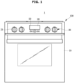
- FIG. 1 illustrates a cooking apparatus according to the present disclosure.
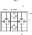
- FIG. 2 illustrates a top surface of a cooking device provided in the cooking apparatus illustrated in FIG. 1 .
- a cooking apparatus 1 may include a main body 10 forming an outer appearance thereof.
- a cooking device 100 may be provided on an upper portion of the main body 10.
- the cooking device 100 is provided such that a cooking container may be placed thereon, and may be configured to supply heat to the cooking container to cook food in the cooking container.
- the cooking device 100 is a gas range that supplies heat using gas.
- a cooking space provided to be sealed by a door may be formed in a lower portion of the main body 10, and a cooking device configured to apply heat to the cooking space to cook food by dry heat may be additionally provided.
- the cooking device provided in the lower portion of the main body 10 may be an oven.
- the cooking apparatus 1 may include a user interface 20 disposed on the main body 10.
- the user interface 20 may input and/or output cooking information of the cooking apparatus 1.
- the user interface 20 may include inputs 21 and 22 to input cooking information and a display 26 to display cooking information.
- the inputs 21 and 22 may include the first input 21 provided in a knob dial type and the second input 22 provided in a button type.
- the first input 21 provided in a knob dial type is referred to as the knob 21.
- the display 26 may display information input to the inputs 21 and 22.
- the display 26 may display cooking information of the cooking apparatus 1.
- the display 26 may be provided as a touch screen. In this case, a user may input a command for controlling the cooking apparatus 1 through the display 26.
- the cooking device 100 may include an upper plate 101 covering an upper side of the main body 10, a container supporter 103 detachably provided on an upper side of the upper plate 101 to support a cooking container, and a range assembly 110 disposed on the upper plate 101 and configured to generate heat.
- a plurality of the range assemblies 110 may be provided, and the plurality of range assemblies 110 may be the same or different from each other in maximum output level.
- the container supporter 103 forms a pair with one of the range assembly 110 and may be positioned around the paired range assembly 110 to support a cooking container located in the paired range assembly 110.
- the container supporter 103 may include a frame 103a in contact with the upper plate 101, and at least three support legs 103b protruding from the frame 103a to support a cooking container.
- the at least three support legs 103b may allow a cooking container to be placed at a predetermined distance from the range assembly 110.
- the container supporter 103 may include a frame 103c having a size to accommodate at least two of the range assemblies 110, and a plurality of support legs 103d each protruding from the frame 103c toward the at least two of the range assemblies.
- the plurality of support legs 103d may include a common support leg 103e in which at least two of the support legs facing the range assemblies 110 different from each other are connected to each other.
- the container supporters 103 may be provided in a single form for each of the range assemblies 110, may be provided in a form of being connected to each other as a whole, and may be provided in a form of being connected to each other in only a portion.
- the shape and size of outer sides of the frames 103a and 103c of the container supporter 103 correspond to the shape and size of an outer side of the upper plate 101, respectively. Accordingly, the container supporter 103 may be fixedly disposed on the upper plate 101.
- FIG. 3 schematically illustrates a configuration of a range assembly illustrated in FIG. 2 .
- the configuration of the range assembly 110 will be described with reference to FIG. 3 .
- the plurality of range assemblies 110 may be provided as described above, for convenience of description, only one of the range assembly 110 will be described as an example.
- the range assembly 110 includes a gas valve 111 to receive gas from the outside.
- the gas valve 111 guides gas supplied from an external gas supply source (not shown) to the gas passage 121.
- the gas valve 111 may open and close a flow passage through which gas supplied from the external gas supply source moves to the gas passage 121.
- the gas valve 111 adjusts the degree of opening of a gas supply passage as the knob 21 rotates. For example, when the knob 21 is rotated by 90 degrees, the gas valve 111 may open the gas supply passage to a maximum size, and when the knob 21 is further rotated up to 270 degrees, the gas valve 111 may reduce the size of the gas supply passage to open the gas supply passage to the minimum size.
- the gas valve 111 may be one of a manual valve, a solenoid valve, and a modulating valve.
- the range assembly 110 includes a modulating valve 112 to open and close the gas passage 121.
- the modulating valve 112 is disposed on the gas passage 121.
- the modulating valve 112 is connected to a controller 130 to be controlled by the controller 130.
- the modulating valve 112 may be a solenoid valve.
- the range assembly 110 includes a boosting valve 113 disposed on a boosting passage 122 branched from the gas passage 121.
- the boosting valve 113 is provided to open and close the boosting passage 122.
- the boosting valve 113 is connected to the controller 130 to be controlled by the controller 130.
- the boosting valve 113 may be a solenoid valve.
- the modulating valve 112 and the boosting valve 113 may be disposed in parallel on a single frame 119. Although not shown, the modulating valve 112 and the boosting valve 113 may be disposed in series on a single frame. Also, the modulating valve 112 and the boosting valve 113 are not disposed on a single frame and may be disposed separately.
- the range assembly 110 includes a first nozzle 114.
- the first nozzle 114 may limit an amount by which gas passed through the modulating valve 112 is supplied to a heating device 116 when the range assembly 110 is operated in a normal mode. Specifically, the first nozzle 114 may limit the amount of gas supplied to the heating device 116 when the range assembly 110 is operated in the normal mode.
- the first nozzle 114 is disposed at the rear of the modulating valve 112 (that is, to the right of the modulating valve 112 in FIG. 3 ) along a direction in which gas in the gas passage 121 flows (that is, from left to right in FIG. 3 ).
- the range assembly 110 includes a second nozzle 115.
- the second nozzle 115 may limit an amount by which gas passed through the boosting valve 113 is supplied to the heating device 116 when the range assembly 110 is operated in a boosting mode. Specifically, the second nozzle 115 may limit the amount by which gas passed through the boosting valve 113 and the first nozzle 114 is supplied to the heating device 116.
- the heating device 116 is configured to apply heat to a cooking container as gas is supplied through the gas passage 121 and is ignited by an ignition device 118.
- the range assembly 110 includes a sensor 117.
- the sensor 117 may be mounted on a shaft 111a of the gas valve 111.
- the sensor 117 may be disposed adjacent to the gas valve 111.
- the sensor 117 may detect a rotation position of the knob 21 and transmit information on the rotation position of the knob 21 to the controller 130.
- the sensor 117 may detect and transmit this position to the controller 130, and the controller 130 may open the boosting valve 113 so that the range assembly 110 may be operated in the boosting mode. At this time, the controller 130 may also open the modulating valve 112.
- the sensor 117 may be configured not to transmit separate information to the controller 130 when the knob 21 deviates from the boosting mode point. Accordingly, the controller 130 may close the boosting valve 113 so that the range assembly 110 operates in the normal mode. In this case, the controller 130 may open the modulating valve 112. With the above configuration, the range assembly 110 according to an embodiment of the present disclosure may easily operate the boosting mode with a relatively simple configuration by the sensor 117.
- the ignition device 118 is provided such that the heating device 116 is ignited when gas is supplied to the heating device 116.
- the ignition device 118 is connected to the controller 130 to be controlled by the controller 130.
- the gas passage 121 is configured to guide gas supplied through the gas valve 111 to the heating device 116.
- the modulating valve 112 and the first nozzle 114 may be disposed on the gas passage 121.
- the second nozzle 115 may be disposed at one end of the gas passage 121 close to the heating device 116.
- the boosting passage 122 is provided to be branched and extend from one portion of the gas passage 121 and to be joined to the other portion of the gas passage 121.
- the one portion of the gas passage 121 to which the boosting passage 122 is branched is disposed in front of the other portion of the gas passage 121 where the boosting passage 122 is joined to the gas passage 121, based on a direction in which the gas flows (that is, on the left based on FIG. 3 ).
- the boosting valve 113 is disposed on the boosting passage 122.
- the controller 130 controls the operation of the range assembly 110.
- the controller 130 may receive position information of the knob 21 from the sensor 117.
- the controller 130 is connected to the modulating valve 112 to control the opening and closing operation of the modulating valve 112.
- the controller 130 is connected to the boosting valve 113 to control the opening and closing operation of the boosting valve 113.
- the controller 130 is connected to the ignition device 118 to control the ignition device 118 to ignite the heating device 116 when the knob is positioned at an ignition point.
- the controller 130 may be connected to a notification device 141 to turn on the notification device 141 when the range assembly 110 is operated in the boosting mode.
- the controller 130 may be implemented as a memory (not shown) for storing an algorithm for controlling the operation of components in the range assembly 110 or a data for a program reproducing the algorithm and a processor (not shown) for performing the above-described operations using data stored in the memory.
- the memory may be implemented as a separate chip from the processor, and may be implemented as a single chip with the processor.
- the range assembly 110 may include the notification device 141 to allow a user to recognize the boosting mode by being lit when the knob 21 is positioned at the boosting mode point.
- the range assembly 110 may further include an ignition detection means capable of detecting whether the heating device 116 is ignited, and the ignition detection means may include an ignition sensor or an ignition detection electrode. The detection result may be provided to the controller 130.
- Some components illustrated in FIG. 3 may be software and/or hardware components such as Field Programmable Gate Array (FPGA) and Application Specific Integrated Circuit (ASIC).
- FPGA Field Programmable Gate Array
- ASIC Application Specific Integrated Circuit
- FIG. 4 illustrates for explaining a temperature of a cooking container that changes by the operation of the range assembly described above and a method of operating each valve of the range assembly.
- the controller 130 closes the modulating valve 112 and the boosting valve 113 so that gas is not supplied to the heating device 116 when the knob is positioned at a first point (initial point, for example, the point of 0 degrees).
- the controller 130 opens the modulating valve 112 and turns on the ignition device 118 to ignite the heating device 116.
- the conventional cooking apparatus 1 when a temperature of a cooking container reaches a certain level, the conventional cooking apparatus 1 reduces the rate of increase in the temperature of the cooking container at a time point t NMa to prevent fire, and in the case of the conventional cooking apparatus 1, gas supplied to the ignition device 118 may be controlled only by only one valve, so that it takes a long time (t NMa ) to increase the temperature of gas to the certain level.
- the boosting valve 113 and the modulating valve 112 are provided in the cooking apparatus 1, so that it takes a time (t NMb ) shorter than before to increase the temperature of gas to the certain level.
- the controller 130 of the cooking apparatus 1 operates the boosting mode when the knob is positioned at a third point (boosting point, for example, the point of 90 degrees), and opens both the boosting valve 113 and the modulating valve 112 in the boosting mode.
- boosting point for example, the point of 90 degrees
- the gas supply is not limited by the first nozzle 114 in the boosting passage 122, so that a large amount of gas may be quickly supplied to the heating device 116.
- the controller 130 terminates the boosting mode and operates the normal mode when a preset boosting time elapses or the knob position deviates from the third point (for example, when the knob position is over 90 degrees and less than 270 degrees).
- the controller 130 opens the modulating valve 112 and closes the boosting valve 113 in the normal mode.
- the normal mode may include a normal max mode of continuously closing the boosting valve 113 and continuously opening the modulating valve 112 when the boosting time elapses, and a normal simmer mode of continuously closing the boosting valve 113 and intermittently opening and closing the modulating valve 112 when the knob position deviates from the third point.
- the controller 130 may not only continuously open the boosting valve 113, but also intermittently repeatedly control the opening and closing of the boosting valve 113. Also, the controller may continuously open the modulating valve 112 in the boosting mode.
- the controller 130 may operate the normal max mode, close the boosting valve 113, and continuously open the modulating valve 112.
- the supply rate of gas supplied to the heating device 116 may be adjusted by the intermittent control of the boosting valve 113 in the boosting mode, and thus the rate of temperature increase of the cooking container may also be adjusted.
- the controller 130 may operate the normal simmer mode.
- the controller 130 may not only continuously open the modulating valve 112, but also intermittently repeatedly control the opening and closing of the modulating valve 112. However, as in normal max mode, the controller continuously closes the boosting valve 113 in the normal simmer mode.
- the controller 130 may adjust the opening duration and the closing duration of the modulating valve 112 according to the position of the knob. For example, the controller 130 may repeatedly perform the operation of opening the modulating valve 112 for 10 seconds and closing for 50 seconds when the knob is positioned at a fourth point (for example, at the point of 120 degrees), and may repeatedly perform the operation of opening the modulating valve 112 for 20 seconds and closing for 40 seconds when the knob is positioned at a fifth point (for example, at the point of 150 degrees).
- the controller 130 may gradually increase the opening duration of the modulating valve 112 when the knob is positioned at a preset automatic adjustment point (for example, more than the point of 210 degrees and less than the point of 360 degrees).
- the controller 130 may perform the operations of opening the modulating valve 112 for 10 seconds and closing for 50 seconds and then opening for 20 seconds and closing for 40 seconds, and then opening for 30 seconds and closing for 30 seconds, and then opening for 40 seconds and closing for 20 seconds, and then repeatedly opening for 50 seconds and closing for 10 seconds.
- both the modulating valve 112 and the boosting valve 113 are closed, so that gas is not supplied to the heating device 116.
- the knob may return to the third point from a point deviating from the third point, and the controller 130 may operate the boosting mode again.
- the controller 130 of the cooking apparatus 1 determines whether a preset boosting delay time (for example, 5 minutes) has elapsed after the boosting mode is operated in order to reduce a risk due to excessive continuation of the boosting mode, and may operate the boosting mode again only when the boosting delay time elapses and the knob is positioned at the second position.
- a preset boosting delay time for example, 5 minutes
- the knob When the user attempts to ignite the heating device 116 again, the knob may return to the first point from a point deviating from the first point, and the controller 130 may operate the ignition device 118 again.
- the controller 130 of the cooking apparatus 1 determines whether a preset ignition time (for example, 1 minute) has elapsed after the ignition device 118 is operated in order to reduce a risk due to excessive operation of the ignition device 118, and may operate the ignition device 118 again only when the knob is positioned at the first point after the ignition time elapses.
- a preset ignition time for example, 1 minute
- FIG. 5 is a flowchart of a method of controlling the cooking apparatus according to an embodiment of the present disclosure.
- the first point is a point where a rotation angle of the knob that is physically rotated is 0 degrees
- the second point is a point where the rotation angle of the knob is 45 degrees
- the third point is a point where the rotation angle of the knob is 90 degrees
- the fourth and fifth points are points where the rotation angle of the knob exceeds 90 degrees and is 210 degrees or less, respectively
- a sixth point is a point where the rotation angle of the knob exceeds 210 degrees, but each point may be positioned at a different point.
- the cooking apparatus 1 closes both the modulating valve 112 and the boosting valve 113 when the knob is positioned at 0 degrees ("YES" in 1111) (1112). Thereafter, when the knob is positioned at the point of 45 degrees ("YES” in 1113), the cooking apparatus 1 opens the modulating valve 112 and closes the boosting valve 113 to ignite the heating device 116 by operating the ignition device 118 while suppling gas to the heating device 116 (1114).
- the cooking apparatus 1 operates the boosting mode and opens the modulating valve 112 and the boosting valve 113 (1116). In this case, the cooking apparatus 1 may intermittently open the boosting valve 113 and adjust the opening duration, thereby controlling the rate of temperature increase.
- the cooking apparatus 1 may operate the boosting mode only for the preset boosting time. In this case, the cooking apparatus 1 may automatically operate the normal max mode when the boosting time elapses, and may open the modulating valve 112, but close the boosting valve 113.
- the cooking apparatus 1 may operate the normal simmer mode when the knob deviates from the point of 90 degrees ("NO" in 1115), and may intermittently open the modulating valve 112 according to the position of the knob in a state of closing the boosting valve 113 when the knob is positioned at a point of 210 degrees or less (“NO" in 1117) (1118).
- the cooking apparatus 1 may increase the opening time of the modulating valve 112 per any one period and decrease the closing time.
- the cooking apparatus 1 may decrease the opening time of the modulating valve 112 per any one period and increase the closing time.
- the cooking apparatus 1 determines that the knob is positioned at the automatic adjustment point, and may gradually increase the opening time of the modulating valve 112 per any one period in a state of closing the boosting valve 113.
- the cooking apparatus 1 may perform the operations of opening the modulating valve 112 for 10 seconds and closing for 50 seconds and then opening for 20 seconds and closing for 40 seconds, and then opening for 30 seconds and closing for 30 seconds, and then opening for 40 seconds and closing for 20 seconds, and then repeatedly opening for 50 seconds and closing for 10 seconds.
- both the modulating valve 112 and the boosting valve 113 are closed, and thus gas is not supplied to the heating device 116.
- the disclosed embodiments may be implemented in the form of a recording medium storing instructions executable by a computer.
- the instructions may be stored in the form of program code, and when executed by a processor, a program module may be created to perform the operations of the disclosed embodiments.
- the recording medium may be implemented as a computer-readable recording medium.
- the computer-readable recording medium includes various kinds of recording media in which instructions which may be decrypted by a computer are stored.
- a ROM Read Only Memory
- RAM Random Access Memory
- magnetic tape a magnetic tape
- magnetic disk a magnetic disk
- flash memory an optical data storage device, and the like.
Landscapes
- Engineering & Computer Science (AREA)
- Chemical & Material Sciences (AREA)
- Combustion & Propulsion (AREA)
- Mechanical Engineering (AREA)
- General Engineering & Computer Science (AREA)
- Cookers (AREA)
- Electric Ovens (AREA)
- Feeding And Controlling Fuel (AREA)
Description
- The present invention relates to a cooking apparatus and a control method thereof, and more particularly, to a cooking apparatus having a boosting function and a control method thereof.
- In general, a cooking apparatus is a device that cooks by heating food, and is largely classified into a method of generating heat for heating food using electricity and a method of generating heat for heating food using gas.
- Such cooking apparatus includes a gas range, an oven, an electric range, and the like.
- A gas range needs to shorten the cooking time by applying heat of a relatively high temperature to the beginning of cooking and applying a relatively appropriate amount of heat to the middle and/or end of cooking.
- A conventional gas range needs to include a separate structure in order to shorten the cooking time by providing a relatively large amount of heat at the beginning of cooking.
- In addition, in a conventional gas range, when the amount of gas supplied during a cooking process changes rapidly, or when a relatively small amount of heat is provided, a fire may goes out as ambient air flows into a heating device to which gas is supplied.
-
- The present invention
is directed to providing a cooking apparatus capable of controlling a boosting mode with a relatively simple configuration, and a control method thereof. - Further, the present invention is directed to providing a cooking apparatus capable of preventing a risk due to a fire when the amount of gas changes rapidly configuration, and a control method thereof.
- Further, the present invention is directed to providing a cooking apparatus capable of preventing a fire from being turned off when a relatively small amount of heat is provided to a heating device, and a control method thereof.
- In accordance with an aspect of the present invention, there is provided a cooking apparatus according to
claim 1. Optional features are set out in the dependent claims. - The cooking apparatus may further include a frame on which the modulating valve and the boosting valve are mounted.
- The first nozzle may be mounted on the frame.
- A size of an opening of the second nozzle may be larger than a size of an opening of the first nozzle.
- When the knob is positioned at a preset second point, the controller may operate a boosting mode to open the boosting valve and the modulating valve.
- When the knob is positioned at a preset second point, the controller may open the modulating valve and intermittently open the boosting valve.
- When the knob is positioned at a preset second point, the controller may open the modulating valve and intermittently open the boosting valve, and when a preset boosting time elapses, the controller may close the boosting valve.
- When the knob is positioned at a preset third point, the controller may open the modulating valve and close the boosting valve.
- When the knob is positioned at a preset third point, the controller may close the boosting valve and intermittently open the modulating valve.
- When the knob deviates from the first point and the second point, the controller may close the boosting valve and control an opening time of the modulating valve according to the position of the knob.
- When the knob returns to the first point again in a state of deviating from the first point, the controller may determine whether a preset ignition time has elapsed after the ignition device is operated, and may determine whether to re-operate the ignition device based on whether the preset ignition time has elapsed.
- When the knob returns to the second point again in a state of deviating from the second point, the controller may determine whether a preset boosting delay time has elapsed after the boosting mode is operated, and may determine whether to re-operate the boosting mode based on whether the preset boosting delay time has elapsed.
- In accordance with another aspect of the present invention, there is provided a method of controlling a cooking apparatus according to
claim 10. - The method may further include operating a boosting mode to open the boosting valve and the modulating valve when the knob is positioned at a preset second point.
- The method may further include opening the modulating valve and intermittently opening the boosting valve when the knob is positioned at a preset second point.
- The method may further include opening the modulating valve and intermittently opening the boosting valve when the knob is positioned at a preset second point, and closing the boosting valve when a preset boosting time elapses.
- The method may further include opening the modulating valve and closing the boosting valve when the knob is positioned at a preset third point.
- The method may further include closing the boosting valve and controlling an opening time of the modulating valve according to the position of the knob when the knob deviates from the first point and the second point.
- A cooking apparatus according to an embodiment of the present disclosure can control a boosting mode only by rotating a knob, so that convenience of use can be improved.
- Further, the cooking apparatus according to an embodiment of the present disclosure includes a control valve capable of adjusting the degree of opening of a gas passage, so that a risk due to fire can be prevented even when the amount of gas changes rapidly, and a fire can be prevented from going out even when a relatively small amount of heat is provided.
-
-
FIG. 1 illustrates a cooking apparatus. -
FIG. 2 illustrates a top surface of a cooking device provided in the cooking apparatus illustrated inFIG. 1 . -
FIG. 3 schematically illustrates a configuration of a range assembly illustrated inFIG. 2 . -
FIG. 4 illustrates for explaining a temperature of a cooking container that changes by an operation of the range assembly and a method of operating each valve of the range assembly. -
FIG. 5 is a flowchart of a method of controlling the cooking apparatus. - The embodiments described in the present specification and the configurations shown in the drawings are only examples of preferred embodiments of the present disclosure. It will be understood that embodiments that do not fall within the scope of the appended claims are not covered by the claimed invention.
- Like reference numbers or signs in the various drawings of the application represent parts or components that perform substantially the same functions.
- The terms used herein are for the purpose of describing the embodiments and are not intended to restrict and/or to limit the present disclosure. For example, the singular expressions herein may include plural expressions, unless the context clearly dictates otherwise. Also, the terms "comprises" and "has" are intended to indicate that there are features, numbers, steps, operations, elements, parts, or combinations thereof described in the specification, and do not exclude the presence or addition of one or more other features, numbers, steps, operations, elements, parts, or combinations thereof.
- It will be understood that, although the terms first, second, etc. may be used herein to describe various components, these components should not be limited by these terms. These terms are only used to distinguish one component from another. For example, without departing from the scope of the present disclosure, the first component may be referred to as a second component, and similarly, the second component may also be referred to as a first component. The term "and/or" includes any combination of a plurality of related items or any one of a plurality of related items.
- In this specification, the terms "front end," "rear end," "upper portion," "lower portion," "upper end" and "lower end" used in the following description are defined with reference to the drawings, and the shape and position of each component are not limited by these terms.
- Reference numerals used in operations are provided for convenience of description, without describing the order of the operations, and the operations may be executed in a different order from the stated order unless a specific order is definitely specified in the context.
- Hereinafter, embodiments of the present disclosure will be described in detail with reference to the accompanying drawings.
-
FIG. 1 illustrates a cooking apparatus according to the present disclosure.FIG. 2 illustrates a top surface of a cooking device provided in the cooking apparatus illustrated inFIG. 1 . - Referring to
FIG. 1 , acooking apparatus 1 may include amain body 10 forming an outer appearance thereof. Acooking device 100 may be provided on an upper portion of themain body 10. Thecooking device 100 is provided such that a cooking container may be placed thereon, and may be configured to supply heat to the cooking container to cook food in the cooking container. Thecooking device 100 is a gas range that supplies heat using gas. - Although not shown, a cooking space provided to be sealed by a door may be formed in a lower portion of the
main body 10, and a cooking device configured to apply heat to the cooking space to cook food by dry heat may be additionally provided. The cooking device provided in the lower portion of themain body 10 may be an oven. - The
cooking apparatus 1 may include auser interface 20 disposed on themain body 10. Theuser interface 20 may input and/or output cooking information of thecooking apparatus 1. Theuser interface 20 may includeinputs display 26 to display cooking information. - The
inputs first input 21 provided in a knob dial type and thesecond input 22 provided in a button type. Hereinafter, thefirst input 21 provided in a knob dial type is referred to as theknob 21. - The
display 26 may display information input to theinputs display 26 may display cooking information of thecooking apparatus 1. Thedisplay 26 may be provided as a touch screen. In this case, a user may input a command for controlling thecooking apparatus 1 through thedisplay 26. - Referring to
FIG. 2 , thecooking device 100 may include anupper plate 101 covering an upper side of themain body 10, acontainer supporter 103 detachably provided on an upper side of theupper plate 101 to support a cooking container, and arange assembly 110 disposed on theupper plate 101 and configured to generate heat. - A plurality of the
range assemblies 110 may be provided, and the plurality ofrange assemblies 110 may be the same or different from each other in maximum output level. - The
container supporter 103 forms a pair with one of therange assembly 110 and may be positioned around the pairedrange assembly 110 to support a cooking container located in the pairedrange assembly 110. - The
container supporter 103 may include a frame 103a in contact with theupper plate 101, and at least three support legs 103b protruding from the frame 103a to support a cooking container. - The at least three support legs 103b may allow a cooking container to be placed at a predetermined distance from the
range assembly 110. - The
container supporter 103 may include a frame 103c having a size to accommodate at least two of therange assemblies 110, and a plurality of support legs 103d each protruding from the frame 103c toward the at least two of the range assemblies. - The plurality of support legs 103d may include a common support leg 103e in which at least two of the support legs facing the
range assemblies 110 different from each other are connected to each other. - As described above, when the plurality of
range assemblies 110 is provided, thecontainer supporters 103 may be provided in a single form for each of therange assemblies 110, may be provided in a form of being connected to each other as a whole, and may be provided in a form of being connected to each other in only a portion. - The shape and size of outer sides of the frames 103a and 103c of the
container supporter 103 correspond to the shape and size of an outer side of theupper plate 101, respectively. Accordingly, thecontainer supporter 103 may be fixedly disposed on theupper plate 101. -
FIG. 3 schematically illustrates a configuration of a range assembly illustrated inFIG. 2 . - Hereinafter, the configuration of the
range assembly 110 will be described with reference toFIG. 3 . Although the plurality ofrange assemblies 110 may be provided as described above, for convenience of description, only one of therange assembly 110 will be described as an example. - Referring to
FIG. 3 , therange assembly 110 includes agas valve 111 to receive gas from the outside. Thegas valve 111 guides gas supplied from an external gas supply source (not shown) to thegas passage 121. Thegas valve 111 may open and close a flow passage through which gas supplied from the external gas supply source moves to thegas passage 121. Thegas valve 111 adjusts the degree of opening of a gas supply passage as theknob 21 rotates. For example, when theknob 21 is rotated by 90 degrees, thegas valve 111 may open the gas supply passage to a maximum size, and when theknob 21 is further rotated up to 270 degrees, thegas valve 111 may reduce the size of the gas supply passage to open the gas supply passage to the minimum size. Thegas valve 111 may be one of a manual valve, a solenoid valve, and a modulating valve. - The
range assembly 110 includes a modulatingvalve 112 to open and close thegas passage 121. The modulatingvalve 112 is disposed on thegas passage 121. The modulatingvalve 112 is connected to acontroller 130 to be controlled by thecontroller 130. The modulatingvalve 112 may be a solenoid valve. - The
range assembly 110 includes a boostingvalve 113 disposed on a boostingpassage 122 branched from thegas passage 121. The boostingvalve 113 is provided to open and close the boostingpassage 122. The boostingvalve 113 is connected to thecontroller 130 to be controlled by thecontroller 130. The boostingvalve 113 may be a solenoid valve. - The modulating
valve 112 and the boostingvalve 113 may be disposed in parallel on asingle frame 119. Although not shown, the modulatingvalve 112 and the boostingvalve 113 may be disposed in series on a single frame. Also, the modulatingvalve 112 and the boostingvalve 113 are not disposed on a single frame and may be disposed separately. - The
range assembly 110 includes afirst nozzle 114. Thefirst nozzle 114 may limit an amount by which gas passed through the modulatingvalve 112 is supplied to aheating device 116 when therange assembly 110 is operated in a normal mode. Specifically, thefirst nozzle 114 may limit the amount of gas supplied to theheating device 116 when therange assembly 110 is operated in the normal mode. Thefirst nozzle 114 is disposed at the rear of the modulating valve 112 (that is, to the right of the modulatingvalve 112 inFIG. 3 ) along a direction in which gas in thegas passage 121 flows (that is, from left to right inFIG. 3 ). - The
range assembly 110 includes asecond nozzle 115. Thesecond nozzle 115 may limit an amount by which gas passed through the boostingvalve 113 is supplied to theheating device 116 when therange assembly 110 is operated in a boosting mode. Specifically, thesecond nozzle 115 may limit the amount by which gas passed through the boostingvalve 113 and thefirst nozzle 114 is supplied to theheating device 116. - The
heating device 116 is configured to apply heat to a cooking container as gas is supplied through thegas passage 121 and is ignited by anignition device 118. - The
range assembly 110 includes asensor 117. Thesensor 117 may be mounted on ashaft 111a of thegas valve 111. Thesensor 117 may be disposed adjacent to thegas valve 111. Thesensor 117 may detect a rotation position of theknob 21 and transmit information on the rotation position of theknob 21 to thecontroller 130. - For example, when the
knob 21 is positioned at a boosting mode point, thesensor 117 may detect and transmit this position to thecontroller 130, and thecontroller 130 may open the boostingvalve 113 so that therange assembly 110 may be operated in the boosting mode. At this time, thecontroller 130 may also open the modulatingvalve 112. - On the other hand, the
sensor 117 may be configured not to transmit separate information to thecontroller 130 when theknob 21 deviates from the boosting mode point. Accordingly, thecontroller 130 may close the boostingvalve 113 so that therange assembly 110 operates in the normal mode. In this case, thecontroller 130 may open the modulatingvalve 112. With the above configuration, therange assembly 110 according to an embodiment of the present disclosure may easily operate the boosting mode with a relatively simple configuration by thesensor 117. - The
ignition device 118 is provided such that theheating device 116 is ignited when gas is supplied to theheating device 116. Theignition device 118 is connected to thecontroller 130 to be controlled by thecontroller 130. - The
gas passage 121 is configured to guide gas supplied through thegas valve 111 to theheating device 116. The modulatingvalve 112 and thefirst nozzle 114 may be disposed on thegas passage 121. Thesecond nozzle 115 may be disposed at one end of thegas passage 121 close to theheating device 116. - The boosting
passage 122 is provided to be branched and extend from one portion of thegas passage 121 and to be joined to the other portion of thegas passage 121. In this case, the one portion of thegas passage 121 to which the boostingpassage 122 is branched is disposed in front of the other portion of thegas passage 121 where the boostingpassage 122 is joined to thegas passage 121, based on a direction in which the gas flows (that is, on the left based onFIG. 3 ). The boostingvalve 113 is disposed on the boostingpassage 122. - The
controller 130 controls the operation of therange assembly 110. Thecontroller 130 may receive position information of theknob 21 from thesensor 117. Thecontroller 130 is connected to the modulatingvalve 112 to control the opening and closing operation of the modulatingvalve 112. Thecontroller 130 is connected to the boostingvalve 113 to control the opening and closing operation of the boostingvalve 113. Thecontroller 130 is connected to theignition device 118 to control theignition device 118 to ignite theheating device 116 when the knob is positioned at an ignition point. Thecontroller 130 may be connected to anotification device 141 to turn on thenotification device 141 when therange assembly 110 is operated in the boosting mode. - The
controller 130 may be implemented as a memory (not shown) for storing an algorithm for controlling the operation of components in therange assembly 110 or a data for a program reproducing the algorithm and a processor (not shown) for performing the above-described operations using data stored in the memory. In this case, the memory may be implemented as a separate chip from the processor, and may be implemented as a single chip with the processor. - The
range assembly 110 may include thenotification device 141 to allow a user to recognize the boosting mode by being lit when theknob 21 is positioned at the boosting mode point. - Although not shown, the
range assembly 110 may further include an ignition detection means capable of detecting whether theheating device 116 is ignited, and the ignition detection means may include an ignition sensor or an ignition detection electrode. The detection result may be provided to thecontroller 130. - Some components illustrated in
FIG. 3 may be software and/or hardware components such as Field Programmable Gate Array (FPGA) and Application Specific Integrated Circuit (ASIC). - Hereinafter, a process in which the
controller 130 controls each component of therange assembly 110 will be described in detail with reference toFIG. 4 . -
FIG. 4 illustrates for explaining a temperature of a cooking container that changes by the operation of the range assembly described above and a method of operating each valve of the range assembly. - The
controller 130 closes the modulatingvalve 112 and the boostingvalve 113 so that gas is not supplied to theheating device 116 when the knob is positioned at a first point (initial point, for example, the point of 0 degrees). - When the user positions the knob at a second point (ignition point, for example, the point of 45 degrees), the
controller 130 opens the modulatingvalve 112 and turns on theignition device 118 to ignite theheating device 116. - Referring to Ta in FIG. 4A, when a temperature of a cooking container reaches a certain level, the
conventional cooking apparatus 1 reduces the rate of increase in the temperature of the cooking container at a time point tNMa to prevent fire, and in the case of theconventional cooking apparatus 1, gas supplied to theignition device 118 may be controlled only by only one valve, so that it takes a long time (tNMa) to increase the temperature of gas to the certain level. - However, referring to Tb in FIG. 4A, in the case of the
cooking apparatus 1 according to an embodiment, the boostingvalve 113 and the modulatingvalve 112 are provided in thecooking apparatus 1, so that it takes a time (tNMb) shorter than before to increase the temperature of gas to the certain level. - Specifically, the
controller 130 of thecooking apparatus 1 according to an embodiment operates the boosting mode when the knob is positioned at a third point (boosting point, for example, the point of 90 degrees), and opens both the boostingvalve 113 and the modulatingvalve 112 in the boosting mode. - When the boosting
valve 113 is opened in the boosting mode, the gas supply is not limited by thefirst nozzle 114 in the boostingpassage 122, so that a large amount of gas may be quickly supplied to theheating device 116. - The
controller 130 terminates the boosting mode and operates the normal mode when a preset boosting time elapses or the knob position deviates from the third point (for example, when the knob position is over 90 degrees and less than 270 degrees). Thecontroller 130 opens the modulatingvalve 112 and closes the boostingvalve 113 in the normal mode. The normal mode may include a normal max mode of continuously closing the boostingvalve 113 and continuously opening the modulatingvalve 112 when the boosting time elapses, and a normal simmer mode of continuously closing the boostingvalve 113 and intermittently opening and closing the modulatingvalve 112 when the knob position deviates from the third point. - As illustrated in FIG. 4B, in the boosting mode, the
controller 130 may not only continuously open the boostingvalve 113, but also intermittently repeatedly control the opening and closing of the boostingvalve 113. Also, the controller may continuously open the modulatingvalve 112 in the boosting mode. - When a preset boosting time tN elapses, the
controller 130 may operate the normal max mode, close the boostingvalve 113, and continuously open the modulatingvalve 112. - As such, the supply rate of gas supplied to the
heating device 116 may be adjusted by the intermittent control of the boostingvalve 113 in the boosting mode, and thus the rate of temperature increase of the cooking container may also be adjusted. - As illustrated in FIG. 4C, when the knob is deviated from the boosting mode point at a time point tNMb according to the user's manipulation, the
controller 130 may operate the normal simmer mode. - In the normal simmer mode, the
controller 130 may not only continuously open the modulatingvalve 112, but also intermittently repeatedly control the opening and closing of the modulatingvalve 112. However, as in normal max mode, the controller continuously closes the boostingvalve 113 in the normal simmer mode. - In the normal simmer mode, the
controller 130 may adjust the opening duration and the closing duration of the modulatingvalve 112 according to the position of the knob. For example, thecontroller 130 may repeatedly perform the operation of opening the modulatingvalve 112 for 10 seconds and closing for 50 seconds when the knob is positioned at a fourth point (for example, at the point of 120 degrees), and may repeatedly perform the operation of opening the modulatingvalve 112 for 20 seconds and closing for 40 seconds when the knob is positioned at a fifth point (for example, at the point of 150 degrees). - In the normal simmer mode, the
controller 130 may gradually increase the opening duration of the modulatingvalve 112 when the knob is positioned at a preset automatic adjustment point (for example, more than the point of 210 degrees and less than the point of 360 degrees). - For example, when the knob is positioned at the automatic adjustment point, the
controller 130 may perform the operations of opening the modulatingvalve 112 for 10 seconds and closing for 50 seconds and then opening for 20 seconds and closing for 40 seconds, and then opening for 30 seconds and closing for 30 seconds, and then opening for 40 seconds and closing for 20 seconds, and then repeatedly opening for 50 seconds and closing for 10 seconds. - Even when the knob is positioned at a point for supplying the maximum amount of gas, the amount of gas supplied to the
heating device 116 gradually increases, so that an accident due to a sudden increase in the amount of gas may be prevented. - When the user positions the knob back to the first point, both the modulating
valve 112 and the boostingvalve 113 are closed, so that gas is not supplied to theheating device 116. - However, when the user attempts to operate the boosting mode again in the normal simmer mode, the knob may return to the third point from a point deviating from the third point, and the
controller 130 may operate the boosting mode again. - On the other hand, the
controller 130 of thecooking apparatus 1 according to another embodiment determines whether a preset boosting delay time (for example, 5 minutes) has elapsed after the boosting mode is operated in order to reduce a risk due to excessive continuation of the boosting mode, and may operate the boosting mode again only when the boosting delay time elapses and the knob is positioned at the second position. - When the user attempts to ignite the
heating device 116 again, the knob may return to the first point from a point deviating from the first point, and thecontroller 130 may operate theignition device 118 again. - The
controller 130 of thecooking apparatus 1 according to another embodiment determines whether a preset ignition time (for example, 1 minute) has elapsed after theignition device 118 is operated in order to reduce a risk due to excessive operation of theignition device 118, and may operate theignition device 118 again only when the knob is positioned at the first point after the ignition time elapses. - Hereinafter, a method of controlling the
cooking apparatus 1 according to an embodiment will be described with reference toFIG. 5. FIG. 5 is a flowchart of a method of controlling the cooking apparatus according to an embodiment of the present disclosure. - Hereinafter, for convenience of explanation, it will be described for example that the first point is a point where a rotation angle of the knob that is physically rotated is 0 degrees, the second point is a point where the rotation angle of the knob is 45 degrees, the third point is a point where the rotation angle of the knob is 90 degrees, the fourth and fifth points are points where the rotation angle of the knob exceeds 90 degrees and is 210 degrees or less, respectively, and a sixth point is a point where the rotation angle of the knob exceeds 210 degrees, but each point may be positioned at a different point.
- First, the
cooking apparatus 1 according to an embodiment closes both the modulatingvalve 112 and the boostingvalve 113 when the knob is positioned at 0 degrees ("YES" in 1111) (1112). Thereafter, when the knob is positioned at the point of 45 degrees ("YES" in 1113), thecooking apparatus 1 opens the modulatingvalve 112 and closes the boostingvalve 113 to ignite theheating device 116 by operating theignition device 118 while suppling gas to the heating device 116 (1114). - Then, when the knob is positioned at the 90 degree point ("YES" in 1115), the
cooking apparatus 1 operates the boosting mode and opens the modulatingvalve 112 and the boosting valve 113 (1116). In this case, thecooking apparatus 1 may intermittently open the boostingvalve 113 and adjust the opening duration, thereby controlling the rate of temperature increase. - The
cooking apparatus 1 may operate the boosting mode only for the preset boosting time. In this case, thecooking apparatus 1 may automatically operate the normal max mode when the boosting time elapses, and may open the modulatingvalve 112, but close the boostingvalve 113. - Then, the
cooking apparatus 1 may operate the normal simmer mode when the knob deviates from the point of 90 degrees ("NO" in 1115), and may intermittently open the modulatingvalve 112 according to the position of the knob in a state of closing the boostingvalve 113 when the knob is positioned at a point of 210 degrees or less ("NO" in 1117) (1118). - For example, in the normal simmer mode, as the rotation angle of the knob gradually increases, the
cooking apparatus 1 may increase the opening time of the modulatingvalve 112 per any one period and decrease the closing time. On the contrary, as the rotation angle of the knob gradually increases, thecooking apparatus 1 may decrease the opening time of the modulatingvalve 112 per any one period and increase the closing time. - When the knob is positioned at any point exceeding the point of 210 degrees ("YES" in 1117), the
cooking apparatus 1 determines that the knob is positioned at the automatic adjustment point, and may gradually increase the opening time of the modulatingvalve 112 per any one period in a state of closing the boostingvalve 113. - For example, when it is determined that the knob is located at the automatic adjustment point, the
cooking apparatus 1 may perform the operations of opening the modulatingvalve 112 for 10 seconds and closing for 50 seconds and then opening for 20 seconds and closing for 40 seconds, and then opening for 30 seconds and closing for 30 seconds, and then opening for 40 seconds and closing for 20 seconds, and then repeatedly opening for 50 seconds and closing for 10 seconds. - When the knob is again positioned at the point of 0 degrees, both the modulating
valve 112 and the boostingvalve 113 are closed, and thus gas is not supplied to theheating device 116. - Herein, the disclosed embodiments may be implemented in the form of a recording medium storing instructions executable by a computer. The instructions may be stored in the form of program code, and when executed by a processor, a program module may be created to perform the operations of the disclosed embodiments. The recording medium may be implemented as a computer-readable recording medium.
- The computer-readable recording medium includes various kinds of recording media in which instructions which may be decrypted by a computer are stored. For example, there may be a ROM (Read Only Memory), a RAM (Random Access Memory), a magnetic tape, a magnetic disk, a flash memory, an optical data storage device, and the like.
- While the present disclosure has been particularly described with reference to exemplary embodiments, it should be understood by those of skilled in the art that various changes in form and details may be made without departing from the scope of the present invention as defined by the appended claims.
Claims (13)
- A cooking apparatus comprising:a heating device (116);a gas passage (121) to guide gas supplied from the outside to the heating device;a gas valve (111) configured to supply gas to the gas passage;a modulating valve (112) configured to adjust the degree of opening of the gas passage;a boosting passage (122) formed to be branched from a first portion of the gas passage and joined to a second portion of the gas passage positioned in the rear of the first portion along a direction in which gas in the gas passage flows;a boosting valve (113) configured to open and close the boosting passage;a first nozzle (114) disposed between the first portion and the second portion of the gas passage;a second nozzle (115) disposed between the second portion of the gas passage and the heating device;a knob (21) connected to the gas valve and configured to control the gas valve to adjust a degree of opening and closing of a gas supply passage;a sensor (117) configured to detect a position of the knob;an ignition device (118) configured to ignite the heating device; anda controller (130) configured to control opening and closing operations of the modulating valve (112) and control opening and closing operations of the boosting valve (113),wherein when the knob (21) is positioned at a preset first point, the controller (130) operates the ignition device (118), opens the modulating valve (112), and closes the boosting valve (113).
- The cooking apparatus according to claim 1, wherein when the knob (21) is positioned at a preset second point, the controller (130) operates a boosting mode to open the boosting valve (113) and the modulating valve (112).
- The cooking apparatus according to claim 1, wherein when the knob (21) is positioned at a preset second point, the controller (130) opens the modulating valve (112) and intermittently opens the boosting valve (113).
- The cooking apparatus according to claim 1, wherein when the knob (21) is positioned at a preset second point, the controller (130) opens the modulating valve (112) and intermittently opens the boosting valve (113), and when a preset boosting time elapses, the controller closes the boosting valve (113).
- The cooking apparatus according to claim 1, wherein when the knob (21) is positioned at a preset third point, the controller (130) opens the modulating valve (112) and closes the boosting valve (113).
- The cooking apparatus according to claim 1, wherein when the knob (21) is positioned at a preset third point, the controller (130) closes the boosting valve (113) and intermittently opens the modulating valve (112). valve.
- The cooking apparatus according to claim 2, wherein when the knob (21) deviates from the first point and the second point, the controller (130) closes the boosting valve (113) and controls an opening time of the modulating valve (112) according to the position of the knob (21).
- The cooking apparatus according to claim 1, wherein when the knob (21) returns to the first point again in a state of deviating from the first point, the controller (130) determines whether a preset ignition time has elapsed after the ignition device (118) is operated, and determines whether to re-operate the ignition device (118) based on whether the preset ignition time has elapsed.
- The cooking apparatus according to claim 2, wherein when the knob (21) returns to the second point again in a state of deviating from the second point, the controller (130) determines whether a preset boosting delay time has elapsed after the boosting mode is operated, and determines whether to re-operate the boosting mode based on whether the preset boosting delay time has elapsed.
- A method of controlling a cooking apparatus which comprises a heating device (116), a knob (21) connected to a gas valve (111) to control the gas valve to adjust a degree of opening and closing of a gas supply passage, a sensor (117) configured to detect a position of the knob, and an ignition device (118) configured to ignite the heating device, the method comprising:detecting a position of the knob (21); andwhen the knob (21) is positioned at a preset first point, operating the ignition device (118),opening a modulating valve (112) configured to adjust the degree of opening of a gas passage (121), andclosing a boosting valve (113) configured to open and close a boosting passage (122) formed to be branched from a first portion of the gas passage and joined to a second portion of the gas passage positioned in the rear of the first portion along a direction in which gas in the gas passage flows.
- The method according to claim 10, further comprising operating a boosting mode to open the boosting valve (113) and the modulating valve (112) when the knob (21) is positioned at a preset second point.
- The method according to claim 10, further comprising opening the modulating valve (112) and intermittently opening the boosting valve (113) when the knob (21) is positioned at a preset second point.
- The method according to claim 10, further comprising opening the modulating valve (112) and intermittently opening the boosting valve (113) when the knob (21) is positioned at a preset second point, and closing the boosting valve (113) when a preset boosting time elapses.
Applications Claiming Priority (2)
| Application Number | Priority Date | Filing Date | Title |
|---|---|---|---|
| KR1020180045086A KR102467316B1 (en) | 2018-04-18 | 2018-04-18 | Cooking apparatus and control method thereof |
| PCT/KR2018/010726 WO2019203402A1 (en) | 2018-04-18 | 2018-09-13 | Cooking appliance and control method therefor |
Publications (3)
| Publication Number | Publication Date |
|---|---|
| EP3760929A1 EP3760929A1 (en) | 2021-01-06 |
| EP3760929A4 EP3760929A4 (en) | 2021-04-21 |
| EP3760929B1 true EP3760929B1 (en) | 2024-10-30 |
Family
ID=68239573
Family Applications (1)
| Application Number | Title | Priority Date | Filing Date |
|---|---|---|---|
| EP18914952.9A Active EP3760929B1 (en) | 2018-04-18 | 2018-09-13 | Cooking appliance and control method therefor |
Country Status (5)
| Country | Link |
|---|---|
| US (1) | US11592185B2 (en) |
| EP (1) | EP3760929B1 (en) |
| KR (1) | KR102467316B1 (en) |
| CN (1) | CN112005052B (en) |
| WO (1) | WO2019203402A1 (en) |
Families Citing this family (1)
| Publication number | Priority date | Publication date | Assignee | Title |
|---|---|---|---|---|
| US20220275938A1 (en) * | 2017-05-04 | 2022-09-01 | Tkip Holdings, Llc | Flame display system and methods |
Citations (1)
| Publication number | Priority date | Publication date | Assignee | Title |
|---|---|---|---|---|
| WO2007020189A1 (en) * | 2005-08-16 | 2007-02-22 | BSH Bosch und Siemens Hausgeräte GmbH | Device for increasing power for a limited time |
Family Cites Families (19)
| Publication number | Priority date | Publication date | Assignee | Title |
|---|---|---|---|---|
| US4425930A (en) * | 1981-05-08 | 1984-01-17 | Donald Kruto | Fluid flow control apparatus and method |
| FR2523693B1 (en) | 1982-03-16 | 1988-11-10 | Laurent Francois | METHOD AND DEVICE FOR ENSURING THE OPERATING SAFETY OF A BURNER, PARTICULARLY GAS |
| JP3077150B2 (en) * | 1990-02-09 | 2000-08-14 | 松下電器産業株式会社 | Cooking device |
| JP2618105B2 (en) * | 1991-03-29 | 1997-06-11 | リンナイ株式会社 | Ignition control device for combustion equipment |
| US5575638A (en) * | 1994-03-29 | 1996-11-19 | Thermador Corporation | Stove burner simmer control |
| DE19627539A1 (en) * | 1996-07-09 | 1998-01-15 | Gaggenau Werke | Method and device for controlling the flame size of gas-operated cooking or baking devices |
| DE19641920A1 (en) * | 1996-10-11 | 1998-04-16 | Gaggenau Werke | Method and device for controlling the flame size of gas-operated cooking or baking devices |
| IT1296492B1 (en) * | 1997-11-21 | 1999-06-25 | Whirlpool Co | SYSTEM TO INDICATE THE RESIDUAL HEAT OF THE GRIDS OF DOMESTIC GAS COOKING APPLIANCES |
| US20020073985A1 (en) * | 2000-12-18 | 2002-06-20 | Bsh Home Appliances Corporation | Pulsed sequence burner control with valve |
| JP2006002989A (en) * | 2004-06-17 | 2006-01-05 | Rinnai Corp | Heating cooker |
| US8364610B2 (en) | 2005-04-08 | 2013-01-29 | Caterpillar Inc. | Process modeling and optimization method and system |
| CN102066841B (en) * | 2007-09-21 | 2015-10-07 | Bsh家用电器有限公司 | gas stove |
| ES2325197B1 (en) * | 2007-09-28 | 2010-06-04 | Coprecitec, S.L. | "GAS KITCHEN APPLIANCE WITH FLAME POWER REGULATION". |
| KR20090090428A (en) * | 2008-02-21 | 2009-08-26 | 나한도 | Gas Timer Device |
| CN102425813B (en) | 2011-12-16 | 2013-11-20 | 美的集团股份有限公司 | Integrated stove |
| JP5706372B2 (en) | 2012-07-06 | 2015-04-22 | リンナイ株式会社 | Gas stove |
| CN104515156A (en) | 2013-10-08 | 2015-04-15 | 博西华电器(江苏)有限公司 | Gas stove |
| US9841191B2 (en) | 2015-04-22 | 2017-12-12 | Whirlpool Corporation | Appliance with electronically-controlled gas flow to burners |
| US10830451B2 (en) * | 2018-04-10 | 2020-11-10 | Haier Us Appliance Solutions, Inc. | Boosted gas burner assembly and a method of operating the same |
-
2018
- 2018-04-18 KR KR1020180045086A patent/KR102467316B1/en active Active
- 2018-09-13 EP EP18914952.9A patent/EP3760929B1/en active Active
- 2018-09-13 US US17/047,605 patent/US11592185B2/en active Active
- 2018-09-13 CN CN201880092477.3A patent/CN112005052B/en not_active Expired - Fee Related
- 2018-09-13 WO PCT/KR2018/010726 patent/WO2019203402A1/en not_active Ceased
Patent Citations (1)
| Publication number | Priority date | Publication date | Assignee | Title |
|---|---|---|---|---|
| WO2007020189A1 (en) * | 2005-08-16 | 2007-02-22 | BSH Bosch und Siemens Hausgeräte GmbH | Device for increasing power for a limited time |
Also Published As
| Publication number | Publication date |
|---|---|
| WO2019203402A1 (en) | 2019-10-24 |
| KR20190121588A (en) | 2019-10-28 |
| US20210116131A1 (en) | 2021-04-22 |
| CN112005052B (en) | 2023-01-17 |
| EP3760929A4 (en) | 2021-04-21 |
| US11592185B2 (en) | 2023-02-28 |
| CN112005052A (en) | 2020-11-27 |
| EP3760929A1 (en) | 2021-01-06 |
| KR102467316B1 (en) | 2022-11-15 |
Similar Documents
| Publication | Publication Date | Title |
|---|---|---|
| EP3040620B2 (en) | Gas oven and control method thereof | |
| KR102413998B1 (en) | Gas Range | |
| EP3760929A1 (en) | Cooking appliance and control method therefor | |
| KR102785713B1 (en) | Cooking apparatus and controlling method thereof | |
| US6889601B2 (en) | Fryer | |
| KR920008198B1 (en) | Controller of gas cooking stove | |
| KR20210119069A (en) | Smart gas breaker with automatic cooking | |
| JP5080836B2 (en) | Grill equipment | |
| JP7281804B2 (en) | gas cooker | |
| KR100942873B1 (en) | Micro thermal control device of automated gas burner and its control method | |
| CN111750388A (en) | Heating cooker | |
| JP3566031B2 (en) | Gas stove with temperature control function | |
| JP3805550B2 (en) | Cooker | |
| KR100202106B1 (en) | A method controlling the temperature for the gas range | |
| JP2799546B2 (en) | rice cooker | |
| KR101597548B1 (en) | Electric cooker | |
| JP7393180B2 (en) | heating cooker | |
| JPH04198619A (en) | Temperature controller of gas stove | |
| JPH1163505A (en) | Gas cooking stove | |
| JPH116621A (en) | Gas cooking stove with rice boiling function | |
| JP2659323B2 (en) | Cooking equipment | |
| JP2001065868A (en) | Cooking stove having fire extinguishment failure preventing function | |
| JPH10339442A (en) | Gas cooking stove with rice cooking function | |
| KR20140019713A (en) | Smart gas range | |
| JPH0937936A (en) | Rice cooker |
Legal Events
| Date | Code | Title | Description |
|---|---|---|---|
| STAA | Information on the status of an ep patent application or granted ep patent |
Free format text: STATUS: THE INTERNATIONAL PUBLICATION HAS BEEN MADE |
|
| PUAI | Public reference made under article 153(3) epc to a published international application that has entered the european phase |
Free format text: ORIGINAL CODE: 0009012 |
|
| STAA | Information on the status of an ep patent application or granted ep patent |
Free format text: STATUS: REQUEST FOR EXAMINATION WAS MADE |
|
| 17P | Request for examination filed |
Effective date: 20200930 |
|
| AK | Designated contracting states |
Kind code of ref document: A1 Designated state(s): AL AT BE BG CH CY CZ DE DK EE ES FI FR GB GR HR HU IE IS IT LI LT LU LV MC MK MT NL NO PL PT RO RS SE SI SK SM TR |
|
| AX | Request for extension of the european patent |
Extension state: BA ME |
|
| A4 | Supplementary search report drawn up and despatched |
Effective date: 20210319 |
|
| RIC1 | Information provided on ipc code assigned before grant |
Ipc: F24C 3/12 20060101AFI20210315BHEP Ipc: F24C 3/10 20060101ALI20210315BHEP Ipc: F23N 1/00 20060101ALI20210315BHEP |
|
| DAV | Request for validation of the european patent (deleted) | ||
| DAX | Request for extension of the european patent (deleted) | ||
| REG | Reference to a national code |
Ref country code: DE Ref legal event code: R079 Free format text: PREVIOUS MAIN CLASS: F24C0003120000 Ipc: F23D0014060000 Ref country code: DE Ref legal event code: R079 Ref document number: 602018076132 Country of ref document: DE Free format text: PREVIOUS MAIN CLASS: F24C0003120000 Ipc: F23D0014060000 |
|
| GRAP | Despatch of communication of intention to grant a patent |
Free format text: ORIGINAL CODE: EPIDOSNIGR1 |
|
| STAA | Information on the status of an ep patent application or granted ep patent |
Free format text: STATUS: GRANT OF PATENT IS INTENDED |
|
| RIC1 | Information provided on ipc code assigned before grant |
Ipc: F23N 1/00 20060101ALI20240515BHEP Ipc: F24C 3/10 20060101ALI20240515BHEP Ipc: F24C 3/12 20060101ALI20240515BHEP Ipc: F23N 5/20 20060101ALI20240515BHEP Ipc: F23D 14/06 20060101AFI20240515BHEP |
|
| INTG | Intention to grant announced |
Effective date: 20240604 |
|
| GRAS | Grant fee paid |
Free format text: ORIGINAL CODE: EPIDOSNIGR3 |
|
| GRAA | (expected) grant |
Free format text: ORIGINAL CODE: 0009210 |
|
| STAA | Information on the status of an ep patent application or granted ep patent |
Free format text: STATUS: THE PATENT HAS BEEN GRANTED |
|
| AK | Designated contracting states |
Kind code of ref document: B1 Designated state(s): AL AT BE BG CH CY CZ DE DK EE ES FI FR GB GR HR HU IE IS IT LI LT LU LV MC MK MT NL NO PL PT RO RS SE SI SK SM TR |
|
| RAP3 | Party data changed (applicant data changed or rights of an application transferred) |
Owner name: SAMSUNG ELECTRONICS CO., LTD. |
|
| REG | Reference to a national code |
Ref country code: GB Ref legal event code: FG4D |
|
| RIN1 | Information on inventor provided before grant (corrected) |
Inventor name: KITASHIMA, TETSUJI Inventor name: MOON, SEONG CHEOL |
|
| REG | Reference to a national code |
Ref country code: CH Ref legal event code: EP |
|
| REG | Reference to a national code |
Ref country code: IE Ref legal event code: FG4D |
|
| REG | Reference to a national code |
Ref country code: DE Ref legal event code: R096 Ref document number: 602018076132 Country of ref document: DE |
|
| REG | Reference to a national code |
Ref country code: LT Ref legal event code: MG9D |
|
| REG | Reference to a national code |
Ref country code: NL Ref legal event code: MP Effective date: 20241030 |
|
| PG25 | Lapsed in a contracting state [announced via postgrant information from national office to epo] |
Ref country code: HR Free format text: LAPSE BECAUSE OF FAILURE TO SUBMIT A TRANSLATION OF THE DESCRIPTION OR TO PAY THE FEE WITHIN THE PRESCRIBED TIME-LIMIT Effective date: 20241030 Ref country code: IS Free format text: LAPSE BECAUSE OF FAILURE TO SUBMIT A TRANSLATION OF THE DESCRIPTION OR TO PAY THE FEE WITHIN THE PRESCRIBED TIME-LIMIT Effective date: 20250228 Ref country code: PT Free format text: LAPSE BECAUSE OF FAILURE TO SUBMIT A TRANSLATION OF THE DESCRIPTION OR TO PAY THE FEE WITHIN THE PRESCRIBED TIME-LIMIT Effective date: 20250228 |
|
| PG25 | Lapsed in a contracting state [announced via postgrant information from national office to epo] |
Ref country code: NL Free format text: LAPSE BECAUSE OF FAILURE TO SUBMIT A TRANSLATION OF THE DESCRIPTION OR TO PAY THE FEE WITHIN THE PRESCRIBED TIME-LIMIT Effective date: 20241030 Ref country code: FI Free format text: LAPSE BECAUSE OF FAILURE TO SUBMIT A TRANSLATION OF THE DESCRIPTION OR TO PAY THE FEE WITHIN THE PRESCRIBED TIME-LIMIT Effective date: 20241030 |
|
| REG | Reference to a national code |
Ref country code: AT Ref legal event code: MK05 Ref document number: 1737184 Country of ref document: AT Kind code of ref document: T Effective date: 20241030 |
|
| PG25 | Lapsed in a contracting state [announced via postgrant information from national office to epo] |
Ref country code: BG Free format text: LAPSE BECAUSE OF FAILURE TO SUBMIT A TRANSLATION OF THE DESCRIPTION OR TO PAY THE FEE WITHIN THE PRESCRIBED TIME-LIMIT Effective date: 20241030 |
|
| PG25 | Lapsed in a contracting state [announced via postgrant information from national office to epo] |
Ref country code: ES Free format text: LAPSE BECAUSE OF FAILURE TO SUBMIT A TRANSLATION OF THE DESCRIPTION OR TO PAY THE FEE WITHIN THE PRESCRIBED TIME-LIMIT Effective date: 20241030 |
|
| PG25 | Lapsed in a contracting state [announced via postgrant information from national office to epo] |
Ref country code: NO Free format text: LAPSE BECAUSE OF FAILURE TO SUBMIT A TRANSLATION OF THE DESCRIPTION OR TO PAY THE FEE WITHIN THE PRESCRIBED TIME-LIMIT Effective date: 20250130 |
|
| PG25 | Lapsed in a contracting state [announced via postgrant information from national office to epo] |
Ref country code: GR Free format text: LAPSE BECAUSE OF FAILURE TO SUBMIT A TRANSLATION OF THE DESCRIPTION OR TO PAY THE FEE WITHIN THE PRESCRIBED TIME-LIMIT Effective date: 20250131 Ref country code: AT Free format text: LAPSE BECAUSE OF FAILURE TO SUBMIT A TRANSLATION OF THE DESCRIPTION OR TO PAY THE FEE WITHIN THE PRESCRIBED TIME-LIMIT Effective date: 20241030 Ref country code: LV Free format text: LAPSE BECAUSE OF FAILURE TO SUBMIT A TRANSLATION OF THE DESCRIPTION OR TO PAY THE FEE WITHIN THE PRESCRIBED TIME-LIMIT Effective date: 20241030 |
|
| PG25 | Lapsed in a contracting state [announced via postgrant information from national office to epo] |
Ref country code: PL Free format text: LAPSE BECAUSE OF FAILURE TO SUBMIT A TRANSLATION OF THE DESCRIPTION OR TO PAY THE FEE WITHIN THE PRESCRIBED TIME-LIMIT Effective date: 20241030 |
|
| PG25 | Lapsed in a contracting state [announced via postgrant information from national office to epo] |
Ref country code: RS Free format text: LAPSE BECAUSE OF FAILURE TO SUBMIT A TRANSLATION OF THE DESCRIPTION OR TO PAY THE FEE WITHIN THE PRESCRIBED TIME-LIMIT Effective date: 20250130 |
|
| PG25 | Lapsed in a contracting state [announced via postgrant information from national office to epo] |
Ref country code: SM Free format text: LAPSE BECAUSE OF FAILURE TO SUBMIT A TRANSLATION OF THE DESCRIPTION OR TO PAY THE FEE WITHIN THE PRESCRIBED TIME-LIMIT Effective date: 20241030 |
|
| PG25 | Lapsed in a contracting state [announced via postgrant information from national office to epo] |
Ref country code: DK Free format text: LAPSE BECAUSE OF FAILURE TO SUBMIT A TRANSLATION OF THE DESCRIPTION OR TO PAY THE FEE WITHIN THE PRESCRIBED TIME-LIMIT Effective date: 20241030 |
|
| PG25 | Lapsed in a contracting state [announced via postgrant information from national office to epo] |
Ref country code: EE Free format text: LAPSE BECAUSE OF FAILURE TO SUBMIT A TRANSLATION OF THE DESCRIPTION OR TO PAY THE FEE WITHIN THE PRESCRIBED TIME-LIMIT Effective date: 20241030 |
|
| PG25 | Lapsed in a contracting state [announced via postgrant information from national office to epo] |
Ref country code: RO Free format text: LAPSE BECAUSE OF FAILURE TO SUBMIT A TRANSLATION OF THE DESCRIPTION OR TO PAY THE FEE WITHIN THE PRESCRIBED TIME-LIMIT Effective date: 20241030 |
|
| PG25 | Lapsed in a contracting state [announced via postgrant information from national office to epo] |
Ref country code: SK Free format text: LAPSE BECAUSE OF FAILURE TO SUBMIT A TRANSLATION OF THE DESCRIPTION OR TO PAY THE FEE WITHIN THE PRESCRIBED TIME-LIMIT Effective date: 20241030 |
|
| PG25 | Lapsed in a contracting state [announced via postgrant information from national office to epo] |
Ref country code: CZ Free format text: LAPSE BECAUSE OF FAILURE TO SUBMIT A TRANSLATION OF THE DESCRIPTION OR TO PAY THE FEE WITHIN THE PRESCRIBED TIME-LIMIT Effective date: 20241030 |
|
| PG25 | Lapsed in a contracting state [announced via postgrant information from national office to epo] |
Ref country code: IT Free format text: LAPSE BECAUSE OF FAILURE TO SUBMIT A TRANSLATION OF THE DESCRIPTION OR TO PAY THE FEE WITHIN THE PRESCRIBED TIME-LIMIT Effective date: 20241030 |
|
| REG | Reference to a national code |
Ref country code: DE Ref legal event code: R097 Ref document number: 602018076132 Country of ref document: DE |
|
| PLBE | No opposition filed within time limit |
Free format text: ORIGINAL CODE: 0009261 |
|
| STAA | Information on the status of an ep patent application or granted ep patent |
Free format text: STATUS: NO OPPOSITION FILED WITHIN TIME LIMIT |
|
| PG25 | Lapsed in a contracting state [announced via postgrant information from national office to epo] |
Ref country code: SE Free format text: LAPSE BECAUSE OF FAILURE TO SUBMIT A TRANSLATION OF THE DESCRIPTION OR TO PAY THE FEE WITHIN THE PRESCRIBED TIME-LIMIT Effective date: 20241030 |
|
| 26N | No opposition filed |
Effective date: 20250731 |
|
| REG | Reference to a national code |
Ref country code: CH Ref legal event code: H13 Free format text: ST27 STATUS EVENT CODE: U-0-0-H10-H13 (AS PROVIDED BY THE NATIONAL OFFICE) Effective date: 20260425 |