EP3760897A1 - Outboard motor - Google Patents
Outboard motor Download PDFInfo
- Publication number
- EP3760897A1 EP3760897A1 EP20170271.9A EP20170271A EP3760897A1 EP 3760897 A1 EP3760897 A1 EP 3760897A1 EP 20170271 A EP20170271 A EP 20170271A EP 3760897 A1 EP3760897 A1 EP 3760897A1
- Authority
- EP
- European Patent Office
- Prior art keywords
- drive shaft
- gear
- clutch
- shaft
- movable
- Prior art date
- Legal status (The legal status is an assumption and is not a legal conclusion. Google has not performed a legal analysis and makes no representation as to the accuracy of the status listed.)
- Granted
Links
Images




Classifications
-
- F—MECHANICAL ENGINEERING; LIGHTING; HEATING; WEAPONS; BLASTING
- F16—ENGINEERING ELEMENTS AND UNITS; GENERAL MEASURES FOR PRODUCING AND MAINTAINING EFFECTIVE FUNCTIONING OF MACHINES OR INSTALLATIONS; THERMAL INSULATION IN GENERAL
- F16H—GEARING
- F16H3/00—Toothed gearings for conveying rotary motion with variable gear ratio or for reversing rotary motion
- F16H3/02—Toothed gearings for conveying rotary motion with variable gear ratio or for reversing rotary motion without gears having orbital motion
- F16H3/08—Toothed gearings for conveying rotary motion with variable gear ratio or for reversing rotary motion without gears having orbital motion exclusively or essentially with continuously meshing gears, that can be disengaged from their shafts
- F16H3/14—Gearings for reversal only
-
- B—PERFORMING OPERATIONS; TRANSPORTING
- B63—SHIPS OR OTHER WATERBORNE VESSELS; RELATED EQUIPMENT
- B63H—MARINE PROPULSION OR STEERING
- B63H20/00—Outboard propulsion units, e.g. outboard motors or Z-drives; Arrangements thereof on vessels
- B63H20/14—Transmission between propulsion power unit and propulsion element
-
- B—PERFORMING OPERATIONS; TRANSPORTING
- B63—SHIPS OR OTHER WATERBORNE VESSELS; RELATED EQUIPMENT
- B63H—MARINE PROPULSION OR STEERING
- B63H20/00—Outboard propulsion units, e.g. outboard motors or Z-drives; Arrangements thereof on vessels
- B63H20/14—Transmission between propulsion power unit and propulsion element
- B63H20/20—Transmission between propulsion power unit and propulsion element with provision for reverse drive
-
- F—MECHANICAL ENGINEERING; LIGHTING; HEATING; WEAPONS; BLASTING
- F16—ENGINEERING ELEMENTS AND UNITS; GENERAL MEASURES FOR PRODUCING AND MAINTAINING EFFECTIVE FUNCTIONING OF MACHINES OR INSTALLATIONS; THERMAL INSULATION IN GENERAL
- F16H—GEARING
- F16H2200/00—Transmissions for multiple ratios
- F16H2200/20—Transmissions using gears with orbital motion
- F16H2200/203—Transmissions using gears with orbital motion characterised by the engaging friction means not of the freewheel type, e.g. friction clutches or brakes
- F16H2200/2064—Transmissions using gears with orbital motion characterised by the engaging friction means not of the freewheel type, e.g. friction clutches or brakes using at least one positive clutch, e.g. dog clutch
-
- F—MECHANICAL ENGINEERING; LIGHTING; HEATING; WEAPONS; BLASTING
- F16—ENGINEERING ELEMENTS AND UNITS; GENERAL MEASURES FOR PRODUCING AND MAINTAINING EFFECTIVE FUNCTIONING OF MACHINES OR INSTALLATIONS; THERMAL INSULATION IN GENERAL
- F16H—GEARING
- F16H2200/00—Transmissions for multiple ratios
- F16H2200/20—Transmissions using gears with orbital motion
- F16H2200/2094—Transmissions using gears with orbital motion using positive clutches, e.g. dog clutches
Definitions
- the present invention relates to an outboard motor.
- An outboard motor includes a drive shaft and a shift mechanism. Rotation of the drive shaft is transmitted to a propeller shaft, while being switched in direction by the shift mechanism. Accordingly, the rotation of the propeller shaft is switched between a forward moving direction and a backward moving direction.
- a shift mechanism for example, includes an upper gear, an intermediate gear, a lower gear and a dog clutch.
- the upper gear is connected to a first input shaft.
- the dog clutch is unitarily rotated with a second input shaft.
- the intermediate gear is constantly meshed with the upper gear and the lower gear.
- the dog clutch When moved upward, the dog clutch is engaged with the upper gear. Accordingly, the rotation of the first input shaft is transmitted to the second input shaft through the upper gear and the dog clutch.
- the dog clutch When moved downward, the dog clutch is engaged with the lower gear. Accordingly, the rotation of the first input shaft is transmitted to the second input shaft through the upper gear, the intermediate gear, the lower gear and the dog clutch.
- the intermediate gear is used for transmitting rotation in one of forward movement and backward movement without being used for transmitting rotation in the other.
- the intermediate gear is constantly rotated by the rotation transmitted thereto from the drive shaft in both forward movement and backward movement. Because of this, high abrasion resistance is demanded for the intermediate gear.
- an outboard motor includes an engine, a first drive shaft, a second drive shaft, a shift mechanism, a propeller shaft and a transmission mechanism.
- the first drive shaft is connected to the engine and extends in an up-and-down direction.
- the second drive shaft extends in the up-and-down direction.
- the shift mechanism switches a direction of rotation to be transmitted therethrough from the first drive shaft to the second drive shaft.
- the propeller shaft extends in a back-and-forth direction.
- the transmission mechanism transmits the rotation transmitted to the second drive shaft to the propeller shaft.
- the shift mechanism includes a first gear, a second gear, a third gear, a shift member, a first clutch, a second clutch and a third clutch.
- the first gear is disposed to be concentric to the first drive shaft.
- the first gear is rotatable relative to the first drive shaft.
- the second gear is disposed to be concentric to the second drive shaft.
- the second gear is rotatable relative to the second drive shaft.
- the third gear is connected to the first gear and the second gear.
- the third gear reverses the direction of the rotation transmitted to the first gear in transmitting the rotation of the first gear to the second gear.
- the shift member is movable to a first position and a second position.
- the first clutch is connected to the shift member.
- the first clutch couples the second drive shaft to the first drive shaft.
- the first clutch decouples the second drive shaft from the first drive shaft.
- the second clutch is connected to the shift member.
- the second clutch decouples the first gear from the first drive shaft.
- the second clutch couples the first gear to the first drive shaft.
- the third clutch is connected to the shift member. When the shift member is set in the first position, the third clutch decouples the second gear from the second drive shaft. When the shift member is set in the second position, the third clutch couples the second gear to the second drive shaft.
- FIG. 1 is a side view of an outboard motor 1 according to the embodiment.
- the outboard motor 1 is attached to the stern of a watercraft.
- the outboard motor 1 includes an engine 11 and an engine cover 12.
- the engine 11 generates a thrust for propelling the watercraft.
- the engine 11 is disposed inside the engine cover 12.
- the engine 11 includes a crankshaft 13.
- the crankshaft 13 extends in an up-and-down direction as a first direction.
- the up-and-down direction refers the outboard motor 1 in mounting position on a watercraft.
- the outboard motor 1 includes a housing 14, a drive shaft 15, a propeller shaft 16, a clutch 17, a shift mechanism 18, a shift shaft 19 and a transmission mechanism 20.
- the drive shaft 15, the propeller shaft 16, the clutch 17, the shift mechanism 18, the shift shaft 19 and the transmission mechanism 20 are disposed inside the housing 14.
- the housing 14 includes an upper housing 21 and a lower housing 22.
- the lower housing 22 is disposed below the upper housing 21.
- the drive shaft 15 is connected to the crankshaft 13.
- the drive shaft 15 extends in the up-and-down direction.
- FIG. 2 is a cross-sectional side view of a lower part of the outboard motor 1.
- the drive shaft 15 includes a first drive shaft 25 and a second drive shaft 26.
- the first drive shaft 25 is connected to the crankshaft 13.
- the first drive shaft 25 includes an upper shaft 27 and a lower shaft 28.
- the upper shaft 27 and the lower shaft 28 extend in the up-and-down direction.
- the upper shaft 27 is connected to the crankshaft 13.
- the lower shaft 28 is disposed below the upper shaft 27.
- the lower shaft 28 is disposed to be concentric to the upper shaft 27.
- the lower shaft 28 is connected to the upper shaft 27 through the clutch 17.
- the clutch 17 is disposed between the upper shaft 27 and the lower shaft 28.
- the clutch 17 is switched between an engaged state and a disengaged state.
- the clutch 17 is in the engaged state, the lower shaft 28 is connected to the upper shaft 27.
- the clutch 17 is in the disengaged state, the lower shaft 28 is disconnected from the upper shaft 27.
- the clutch 17 includes a plurality of clutch discs. When the plural clutch discs make contact with each other, the clutch 17 is turned to the engaged state. When the plural clutch discs separate from each other, the clutch 17 is turned to the disengaged state.
- the second drive shaft 26 is disposed below the first drive shaft 25.
- the axis (of rotation) of the first drive shaft 25 and that of the second drive shaft 26 are oriented in an identical direction.
- the second drive shaft 26 is disposed to be concentric to the first drive shaft 25.
- the second drive shaft 26 is connected to the first drive shaft 25 through the shift mechanism 18.
- the second drive shaft 26 is connected to the lower shaft 28 of the first drive shaft 25 through the shift mechanism 18.
- the shift mechanism 18 is disposed between the first drive shaft 25 and the second drive shaft 26.
- the shift mechanism 18 is disposed inside the upper housing 21.
- the shift mechanism 18 switches the direction of rotation to be transmitted from the first drive shaft 25 to the second drive shaft 26 between a forward moving direction and a backward moving direction.
- FIGS. 3 to 5 are close-up side views of the shift mechanism 18 and the surroundings thereof.
- the shift mechanism 18 includes a first gear 31, a second gear 32, a third gear 33, a shift member 34, a first clutch 35, a second clutch 36 and a third clutch 37.
- the first gear 31 is disposed to be concentric to the first drive shaft 25.
- the first gear 31 is disposed on the outer periphery of the first drive shaft 25.
- the first gear 31 is rotatably supported by a bearing 51.
- the first gear 31 is rotatable relative to the first drive shaft 25.
- the second gear 32 is disposed to be concentric to the second drive shaft 26.
- the second gear 32 is disposed on the outer periphery of the second drive shaft 26.
- the second gear 32 is rotatably supported by a bearing 52.
- the second gear 32 is rotatable relative to the second drive shaft 26.
- the axis (of rotation) of the first gear 31 and that of the second gear 32 extend in the up-and-down direction.
- the third gear 33 is connected to the first gear 31 and the second gear 32.
- the axis (of rotation) of the third gear 33 extends in a back-and-forth direction as a second direction orthogonal to the first direction.
- the third gear 33 is rotatably supported by a bearing 53.
- the third gear 33 reverses the rotation of the first gear 31 and transmits the reversed rotation to the second gear 32.
- the first to third gears 31 to 33 are bevel gears.
- the first gear 31 is meshed with the third gear 33.
- the third gear 33 is meshed with the second gear 32.
- the shift member 34 is movable in the direction of the axis (of rotation) of the second drive shaft 26. In other words, the shift member 34 is movable in the up-and-down direction.
- the shift member 34 is connected to the shift shaft 19.
- the shift shaft 19 extends in the up-and-down direction.
- the shift shaft 19 may be connected to an actuator (not shown in the drawings).
- the actuator may be, for instance, an electric motor.
- the shift shaft 19 may be driven by the actuator in response to a shift operation performed by an operator.
- the shift shaft 19 may be connected to a shift cable.
- the shift shaft 19 may be driven by the shift cable in response to the shift operation performed by the operator.
- the shift shaft 19 moves the shift member 34 to a first position, a second position and a third position.
- the shift shaft 19 includes a cam mechanism (not shown in the drawings).
- the cam mechanism elevates the shift member 34.
- the cam mechanism lowers the shift member 34.
- the shift mechanism 18 includes a first movable member 54, a first coupling member 55, a second movable member 56 and a second coupling member 57.
- the first movable member 54 is disposed on the outer periphery of the first drive shaft 25.
- the first movable member 54 and the first coupling member 55 are disposed above the first gear 31.
- the first movable member 54 is coupled to the first drive shaft 25 through the first coupling member 55.
- the first movable member 54 and the first coupling member 55 are rotated together with the first drive shaft 25.
- the first drive shaft 25 includes an elongated hole 58 elongated in the direction of the axis of the first drive shaft 25.
- the first coupling member 55 is inserted into the elongated hole 58 of the first drive shaft 25.
- the first coupling member 55 is movable in the axis direction of the first drive shaft 25 along the elongated hole 58 of the first drive shaft 25. Therefore, the first movable member 54 and the first coupling member 55 are movable in the axis direction of the first drive shaft 25.
- the second movable member 56 is disposed on the outer periphery of the second drive shaft 26.
- the second movable member 56 and the second coupling member 57 are disposed between the first gear 31 and the second gear 32.
- the second movable member 56 is coupled to the second drive shaft 26 through the second coupling member 57.
- the second movable member 56 and the second coupling member 57 are rotated together with the second drive shaft 26.
- the second drive shaft 26 includes an elongated hole 59 elongated in the axis direction of the second drive shaft 26.
- the second coupling member 57 is inserted into the elongated hole 59 of the second drive shaft 26.
- the second coupling member 57 is movable in the axis direction of the second drive shaft 26 along the elongated hole 59 of the second drive shaft 26. Therefore, the second movable member 56 and the second coupling member 57 are movable in the axis direction of the second drive shaft 26.
- the shift mechanism 18 includes a first movable shaft 61 and a second movable shaft 62.
- the first movable shaft 61 is disposed inside the first drive shaft 25.
- the first movable shaft 61 is movable in the axis direction of the first drive shaft 25 with respect to the first drive shaft 25.
- the first movable shaft 61 is connected to the first movable member 54 through the first coupling member 55.
- the first coupling member 55 is moved together with the first movable shaft 61 in the axis direction of the first drive shaft 25.
- the second movable shaft 62 is disposed in part inside the second drive shaft 26.
- the second movable shaft 62 protrudes upward from the second drive shaft 26.
- the second movable shaft 62 is connected at an upper portion thereof to the first movable shaft 61.
- the second movable shaft 62 is rotatable about the axis of the second drive shaft 26 with respect to the first movable shaft 61.
- the second movable shaft 62 is movable in the axis direction of the second drive shaft 26 with respect to the second drive shaft 26.
- the second movable shaft 62 is connected to the second movable member 56 through the second coupling member 57.
- the second coupling member 57 is moved together with the second movable shaft 62 in the axis direction of the second drive shaft 26.
- the second movable member 56 is movable up and down in conjunction with the first movable member 54.
- the second movable member 56 is connected to the shift member 34.
- the second movable member 56 is provided with a recess 63 on the outer peripheral surface thereof.
- the recess 63 extends in the circumferential direction of the second movable member 56.
- the distal end of the shift member 34 is disposed inside the recess 63.
- the first to third clutches 35 to 37 are dog clutches. However, the first to third clutches 35 to 37 are not limited to the dog clutches and may be another type of clutches.
- the first clutch 35 is connected to the shift member 34.
- the first clutch 35 includes first clutch teeth 64 and second clutch teeth 65.
- the first clutch teeth 64 are provided on the first drive shaft 25.
- the first clutch teeth 64 are rotated together with the first drive shaft 25.
- the second clutch teeth 65 are provided on the second movable member 56.
- the second clutch teeth 65 are rotated together with the second movable member 56.
- the second clutch teeth 65 are moved together with the second movable member 56 in the up-and-down direction.
- the second clutch teeth 65 are moved toward the first clutch teeth 64.
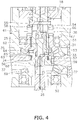
- the second clutch teeth 65 are then meshed with the first clutch teeth 64, whereby the first clutch 35 couples the second drive shaft 26 to the first drive shaft 25. Therefore, when the shift member 34 is set in the first position shown in FIG. 4 , the first clutch 35 couples the second drive shaft 26 to the first drive shaft 25.
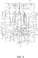
- the shift member 34 is set in either the third position shown in FIG. 3 or the second position shown in FIG. 5 , the first clutch 35 decouples the second drive shaft 26 from the first drive shaft 25.
- the second position is located below the first position.
- the third position is located between the first position and the second position.
- the second clutch 36 is connected to the shift member 34 through the first movable shaft 61, the second movable shaft 62 and the second movable member 56.
- the third gear 33 is located at least in part at an equal height to the first clutch 35 in the up-and-down direction of the outboard motor 1.
- the second clutch 36 includes third clutch teeth 66 and fourth clutch teeth 67.
- the third clutch teeth 66 are provided on the first movable member 54.
- the third clutch teeth 66 are moved together with the first movable member 54 in the up-and-down direction.
- the third clutch teeth 66 are rotated together with the first drive shaft 25.
- the fourth clutch teeth 67 are provided on the first gear 31.
- the fourth clutch teeth 67 are rotated together with the first gear 31.
- the third clutch 37 is connected to the shift member 34.
- the third gear 33 is located at least in part at an equal height to the third clutch 37 in the up-and-down direction of the outboard motor 1.
- the third clutch 37 includes fifth clutch teeth 68 and sixth clutch teeth 69.
- the fifth clutch teeth 68 are provided on the second movable member 56.
- the fifth clutch teeth 68 are rotated together with the second drive shaft 26.
- the fifth clutch teeth 68 are moved together with the second movable member 56 in the up-and-down direction.
- the sixth clutch teeth 69 are provided on the second gear 32.
- the sixth clutch teeth 69 are rotated together with the second gear 32.
- the first clutch 35 decouples the second drive shaft 26 from the first drive shaft 25.
- the second clutch 36 decouples the first gear 31 from the first drive shaft 25.
- the third clutch 37 decouples the second gear 32 from the second drive shaft 26. Because of the above, the rotation of the first drive shaft 25 is not transmitted to the second drive shaft 26. Besides, the rotation of the first drive shaft 25 is not transmitted to the first to third gears 31 to 33.
- the first movable member 54 and the second movable member 56 are both moved upward.
- the first clutch 35 couples the second drive shaft 26 to the first drive shaft 25.
- the second clutch 36 decouples the first gear 31 from the first drive shaft 25.
- the third clutch 37 decouples the second gear 32 from the second drive shaft 26. Because of the above, the rotation of the first drive shaft 25 is transmitted to the second drive shaft 26 through the first clutch 35. Therefore, the second drive shaft 26 is rotated in the forward moving direction that is identical to the rotational direction of the first drive shaft 25. On the other hand, the rotation of the first drive shaft 25 is not transmitted to the first to third gears 31 to 33.
- the first clutch 35 decouples the second drive shaft 26 from the first drive shaft 25.
- the second clutch 36 connects the first gear 31 to the first drive shaft 25.
- the third clutch 37 connects the second gear 32 to the second drive shaft 26. Because of the above, the rotation of the first drive shaft 25 is transmitted to the second drive shaft 26 through the second clutch 36, the first gear 31, the third gear 33, the second gear 32 and the third clutch 37. Therefore, the second drive shaft 26 is rotated in the backward moving direction that is opposite from the rotational direction of the first drive shaft 25.
- FIG. 6 is a close-up side view of the propeller shaft 16 and the transmission mechanism 20.
- the propeller shaft 16 and the transmission mechanism 20 are disposed inside the lower housing 22.
- the propeller shaft 16 extends in the back-and-forth direction.
- the propeller shaft 16 is connected to the second drive shaft 26 through the transmission mechanism 20.
- the propeller shaft 16 includes a first propeller shaft 41 and a second propeller shaft 42.
- a first propeller 43 is attached to the first propeller shaft 41.
- a second propeller 44 is attached to the second propeller shaft 42.
- the second propeller shaft 42 is disposed to be concentric to the first propeller shaft 41.
- the first propeller shaft 41 includes a hole 45 extending in the back-and-forth direction.
- the hole 45 of the first propeller shaft 41 penetrates the first propeller shaft 41 in the direction of the axis (of rotation) of the first propeller shaft 41.
- the second propeller shaft 42 is inserted into the hole 45 of the first propeller shaft 41.
- the second propeller shaft 42 protrudes forward from the first propeller shaft 41.
- the second propeller shaft 42 protrudes backward from the first propeller shaft 41.
- the transmission mechanism 20 transmits rotation of the second drive shaft 26 to the first propeller shaft 41 and the second propeller shaft 42.
- the transmission mechanism 20 includes a first bevel gear 46, a second bevel gear 47 and a third bevel gear 48.
- the first bevel gear 46 is fixed to the second drive shaft 26.
- the second bevel gear 47 is meshed with the first bevel gear 46.
- the second bevel gear 47 is fixed to the first propeller shaft 41.
- the third bevel gear 48 is meshed with the first bevel gear 46.
- the third bevel gear 48 is fixed to the second propeller shaft 42.
- the third bevel gear 48 transmits rotation of the first bevel gear 46 to the second propeller shaft 42 such that the transmitted rotation is oriented in the opposite direction from the rotation of the first propeller shaft 41.
- first and second propeller shafts 41 and 42 are rotated in opposite directions. Fins of the second propeller 44 are twisted in the opposite direction from those of the first propeller 43. Therefore, when the first and second propeller shafts 41 and 42 are rotated in the opposite directions, a thrust generated by the first propeller shaft 41 and that generated by the second propeller shaft 42 are oriented in an identical direction.
- the shift member 34 when the shift member 34 is set in the second position, the rotation of the first drive shaft 25 is transmitted to the second drive shaft 26 through the second clutch 36, the first gear 31, the third gear 33, the second gear 32 and the third clutch 37.
- the shift member 34 When the shift member 34 is set in the first position, the rotation of the first drive shaft 25 is transmitted to the second drive shaft 26 through the first clutch 35 but is not transmitted to the first to third gears 31 to 33. Because of this, the first to third gears 31 to 33 can be enhanced in abrasion resistance.
- the outboard motor 1 includes two propellers. However, as shown in FIG. 7 , the outboard motor 1 may include only one propeller.
- the structure and/or layout of the shift mechanism 18 may not be limited to those/that in the aforementioned embodiment and may be changed.
- the first to third gears 31 to 33 may not be limited to the bevel gears and may be another type of gears.
- FIG. 8 is a view of the shift mechanism 18 according to a modification.
- the first and second gears 31 and 32 are spur gears.
- the third gear 33 includes a plurality of gears 71 to 73.
- the gears 71 to 73 are spur gears.
- the gears 71 and 72 are fixed to a shaft 74.
- the gear 73 is fixed to a shaft 75.
- the gear 71 is meshed with the first gear 31.
- the gear 72 is meshed with the gear 73.
- the gear 73 is meshed with the second gear 32.
- the second drive shaft 26 when the shift member 34 is set in the first position, the second drive shaft 26 is rotated in the forward moving direction.
- the second drive shaft 26 when the shift member 34 is set in the second position, the second drive shaft 26 is rotated in the backward moving direction.
- the shift member 34 when the shift member 34 is set in the second position, the second drive shaft 26 may be rotated in the forward moving direction.
- the shift member 34 when the shift member 34 is set in the first position, the second drive shaft 26 may be rotated in the backward moving direction.
Landscapes
- Engineering & Computer Science (AREA)
- Mechanical Engineering (AREA)
- Chemical & Material Sciences (AREA)
- Combustion & Propulsion (AREA)
- Ocean & Marine Engineering (AREA)
- General Engineering & Computer Science (AREA)
- Structure Of Transmissions (AREA)
- Gear Transmission (AREA)
Abstract
Description
- The present invention relates to an outboard motor.
- An outboard motor includes a drive shaft and a shift mechanism. Rotation of the drive shaft is transmitted to a propeller shaft, while being switched in direction by the shift mechanism. Accordingly, the rotation of the propeller shaft is switched between a forward moving direction and a backward moving direction.
- For example, a shift mechanism, described in
JP 2015-202849 A - In the outboard motor described above, the intermediate gear is used for transmitting rotation in one of forward movement and backward movement without being used for transmitting rotation in the other. However, the intermediate gear is constantly rotated by the rotation transmitted thereto from the drive shaft in both forward movement and backward movement. Because of this, high abrasion resistance is demanded for the intermediate gear.
- It is an object of the present invention to provide an outboard motor to enhance abrasion resistance of a gear used for transmitting rotation outputted from a drive shaft in an outboard motor. According to the present invention said object is solved by an outboard motor having the features of
independent claim 1. Preferred embodiments are laid down in the dependent claims. - According to an aspect of the present disclosure, an outboard motor includes an engine, a first drive shaft, a second drive shaft, a shift mechanism, a propeller shaft and a transmission mechanism. The first drive shaft is connected to the engine and extends in an up-and-down direction. The second drive shaft extends in the up-and-down direction. The shift mechanism switches a direction of rotation to be transmitted therethrough from the first drive shaft to the second drive shaft. The propeller shaft extends in a back-and-forth direction. The transmission mechanism transmits the rotation transmitted to the second drive shaft to the propeller shaft.
- The shift mechanism includes a first gear, a second gear, a third gear, a shift member, a first clutch, a second clutch and a third clutch. The first gear is disposed to be concentric to the first drive shaft. The first gear is rotatable relative to the first drive shaft. The second gear is disposed to be concentric to the second drive shaft. The second gear is rotatable relative to the second drive shaft. The third gear is connected to the first gear and the second gear. The third gear reverses the direction of the rotation transmitted to the first gear in transmitting the rotation of the first gear to the second gear. The shift member is movable to a first position and a second position.
- The first clutch is connected to the shift member. When the shift member is set in the first position, the first clutch couples the second drive shaft to the first drive shaft. When the shift member is set in the second position, the first clutch decouples the second drive shaft from the first drive shaft. The second clutch is connected to the shift member. When the shift member is set in the first position, the second clutch decouples the first gear from the first drive shaft. When the shift member is set in the second position, the second clutch couples the first gear to the first drive shaft. The third clutch is connected to the shift member. When the shift member is set in the first position, the third clutch decouples the second gear from the second drive shaft. When the shift member is set in the second position, the third clutch couples the second gear to the second drive shaft.
-
-
FIG. 1 is a side view of an outboard motor according to an embodiment. -
FIG. 2 is a cross-sectional side view of a lower part of the outboard motor. -
FIG. 3 is a cross-sectional side view of a shift mechanism and the surroundings thereof. -
FIG. 4 is a cross-sectional side view of the shift mechanism and the surroundings thereof. -
FIG. 5 is a cross-sectional side view of the shift mechanism and the surroundings thereof. -
FIG. 6 is a cross-sectional side view of a propeller shaft and a transmission mechanism. -
FIG. 7 is a side view of an outboard motor according to a first modification. -
FIG. 8 is a cross-sectional side view of a shift mechanism according to a second modification. - An embodiment will be hereinafter explained with reference to drawings.
FIG. 1 is a side view of anoutboard motor 1 according to the embodiment. Theoutboard motor 1 is attached to the stern of a watercraft. As shown inFIG. 1 , theoutboard motor 1 includes anengine 11 and anengine cover 12. Theengine 11 generates a thrust for propelling the watercraft. Theengine 11 is disposed inside theengine cover 12. Theengine 11 includes acrankshaft 13. Thecrankshaft 13 extends in an up-and-down direction as a first direction. The up-and-down direction refers theoutboard motor 1 in mounting position on a watercraft. - The
outboard motor 1 includes ahousing 14, adrive shaft 15, apropeller shaft 16, aclutch 17, ashift mechanism 18, ashift shaft 19 and atransmission mechanism 20. Thedrive shaft 15, thepropeller shaft 16, theclutch 17, theshift mechanism 18, theshift shaft 19 and thetransmission mechanism 20 are disposed inside thehousing 14. Thehousing 14 includes anupper housing 21 and alower housing 22. Thelower housing 22 is disposed below theupper housing 21. Thedrive shaft 15 is connected to thecrankshaft 13. Thedrive shaft 15 extends in the up-and-down direction. -
FIG. 2 is a cross-sectional side view of a lower part of theoutboard motor 1. As shown inFIG. 2 , thedrive shaft 15 includes afirst drive shaft 25 and asecond drive shaft 26. Thefirst drive shaft 25 is connected to thecrankshaft 13. Thefirst drive shaft 25 includes anupper shaft 27 and alower shaft 28. Theupper shaft 27 and thelower shaft 28 extend in the up-and-down direction. Theupper shaft 27 is connected to thecrankshaft 13. Thelower shaft 28 is disposed below theupper shaft 27. Thelower shaft 28 is disposed to be concentric to theupper shaft 27. Thelower shaft 28 is connected to theupper shaft 27 through the clutch 17. - The clutch 17 is disposed between the
upper shaft 27 and thelower shaft 28. The clutch 17 is switched between an engaged state and a disengaged state. When the clutch 17 is in the engaged state, thelower shaft 28 is connected to theupper shaft 27. When the clutch 17 is in the disengaged state, thelower shaft 28 is disconnected from theupper shaft 27. For example, the clutch 17 includes a plurality of clutch discs. When the plural clutch discs make contact with each other, the clutch 17 is turned to the engaged state. When the plural clutch discs separate from each other, the clutch 17 is turned to the disengaged state. - The
second drive shaft 26 is disposed below thefirst drive shaft 25. The axis (of rotation) of thefirst drive shaft 25 and that of thesecond drive shaft 26 are oriented in an identical direction. Thesecond drive shaft 26 is disposed to be concentric to thefirst drive shaft 25. Thesecond drive shaft 26 is connected to thefirst drive shaft 25 through theshift mechanism 18. Detailedly, thesecond drive shaft 26 is connected to thelower shaft 28 of thefirst drive shaft 25 through theshift mechanism 18. - The
shift mechanism 18 is disposed between thefirst drive shaft 25 and thesecond drive shaft 26. Theshift mechanism 18 is disposed inside theupper housing 21. Theshift mechanism 18 switches the direction of rotation to be transmitted from thefirst drive shaft 25 to thesecond drive shaft 26 between a forward moving direction and a backward moving direction.FIGS. 3 to 5 are close-up side views of theshift mechanism 18 and the surroundings thereof. As shown inFIG. 3 , theshift mechanism 18 includes afirst gear 31, asecond gear 32, athird gear 33, ashift member 34, a first clutch 35, a second clutch 36 and a third clutch 37. - The
first gear 31 is disposed to be concentric to thefirst drive shaft 25. Thefirst gear 31 is disposed on the outer periphery of thefirst drive shaft 25. Thefirst gear 31 is rotatably supported by abearing 51. Thefirst gear 31 is rotatable relative to thefirst drive shaft 25. Thesecond gear 32 is disposed to be concentric to thesecond drive shaft 26. Thesecond gear 32 is disposed on the outer periphery of thesecond drive shaft 26. Thesecond gear 32 is rotatably supported by abearing 52. Thesecond gear 32 is rotatable relative to thesecond drive shaft 26. The axis (of rotation) of thefirst gear 31 and that of thesecond gear 32 extend in the up-and-down direction. - The
third gear 33 is connected to thefirst gear 31 and thesecond gear 32. The axis (of rotation) of thethird gear 33 extends in a back-and-forth direction as a second direction orthogonal to the first direction. Thethird gear 33 is rotatably supported by abearing 53. Thethird gear 33 reverses the rotation of thefirst gear 31 and transmits the reversed rotation to thesecond gear 32. The first tothird gears 31 to 33 are bevel gears. Thefirst gear 31 is meshed with thethird gear 33. Thethird gear 33 is meshed with thesecond gear 32. - The
shift member 34 is movable in the direction of the axis (of rotation) of thesecond drive shaft 26. In other words, theshift member 34 is movable in the up-and-down direction. Theshift member 34 is connected to theshift shaft 19. Theshift shaft 19 extends in the up-and-down direction. Theshift shaft 19 may be connected to an actuator (not shown in the drawings). The actuator may be, for instance, an electric motor. Theshift shaft 19 may be driven by the actuator in response to a shift operation performed by an operator. Alternatively, theshift shaft 19 may be connected to a shift cable. Theshift shaft 19 may be driven by the shift cable in response to the shift operation performed by the operator. - The
shift shaft 19 moves theshift member 34 to a first position, a second position and a third position. For example, theshift shaft 19 includes a cam mechanism (not shown in the drawings). When theshift shaft 19 is rotated in one direction about the axis thereof, the cam mechanism elevates theshift member 34. When theshift shaft 19 is rotated in the other direction about the axis thereof, the cam mechanism lowers theshift member 34. - The
shift mechanism 18 includes a firstmovable member 54, afirst coupling member 55, a secondmovable member 56 and asecond coupling member 57. The firstmovable member 54 is disposed on the outer periphery of thefirst drive shaft 25. The firstmovable member 54 and thefirst coupling member 55 are disposed above thefirst gear 31. The firstmovable member 54 is coupled to thefirst drive shaft 25 through thefirst coupling member 55. The firstmovable member 54 and thefirst coupling member 55 are rotated together with thefirst drive shaft 25. Thefirst drive shaft 25 includes anelongated hole 58 elongated in the direction of the axis of thefirst drive shaft 25. Thefirst coupling member 55 is inserted into theelongated hole 58 of thefirst drive shaft 25. Thefirst coupling member 55 is movable in the axis direction of thefirst drive shaft 25 along theelongated hole 58 of thefirst drive shaft 25. Therefore, the firstmovable member 54 and thefirst coupling member 55 are movable in the axis direction of thefirst drive shaft 25. - The second
movable member 56 is disposed on the outer periphery of thesecond drive shaft 26. The secondmovable member 56 and thesecond coupling member 57 are disposed between thefirst gear 31 and thesecond gear 32. The secondmovable member 56 is coupled to thesecond drive shaft 26 through thesecond coupling member 57. The secondmovable member 56 and thesecond coupling member 57 are rotated together with thesecond drive shaft 26. Thesecond drive shaft 26 includes anelongated hole 59 elongated in the axis direction of thesecond drive shaft 26. Thesecond coupling member 57 is inserted into theelongated hole 59 of thesecond drive shaft 26. Thesecond coupling member 57 is movable in the axis direction of thesecond drive shaft 26 along theelongated hole 59 of thesecond drive shaft 26. Therefore, the secondmovable member 56 and thesecond coupling member 57 are movable in the axis direction of thesecond drive shaft 26. - The
shift mechanism 18 includes a firstmovable shaft 61 and a secondmovable shaft 62. The firstmovable shaft 61 is disposed inside thefirst drive shaft 25. The firstmovable shaft 61 is movable in the axis direction of thefirst drive shaft 25 with respect to thefirst drive shaft 25. The firstmovable shaft 61 is connected to the firstmovable member 54 through thefirst coupling member 55. Thefirst coupling member 55 is moved together with the firstmovable shaft 61 in the axis direction of thefirst drive shaft 25. - The second
movable shaft 62 is disposed in part inside thesecond drive shaft 26. The secondmovable shaft 62 protrudes upward from thesecond drive shaft 26. The secondmovable shaft 62 is connected at an upper portion thereof to the firstmovable shaft 61. The secondmovable shaft 62 is rotatable about the axis of thesecond drive shaft 26 with respect to the firstmovable shaft 61. The secondmovable shaft 62 is movable in the axis direction of thesecond drive shaft 26 with respect to thesecond drive shaft 26. The secondmovable shaft 62 is connected to the secondmovable member 56 through thesecond coupling member 57. Thesecond coupling member 57 is moved together with the secondmovable shaft 62 in the axis direction of thesecond drive shaft 26. - The second
movable member 56 is movable up and down in conjunction with the firstmovable member 54. The secondmovable member 56 is connected to theshift member 34. The secondmovable member 56 is provided with arecess 63 on the outer peripheral surface thereof. Therecess 63 extends in the circumferential direction of the secondmovable member 56. The distal end of theshift member 34 is disposed inside therecess 63. When theshift member 34 is moved up and down, theshift member 34 presses up and down the firstmovable member 54. Accordingly, the firstmovable member 54 and the secondmovable member 56 are moved up and down. - The first to
third clutches 35 to 37 are dog clutches. However, the first tothird clutches 35 to 37 are not limited to the dog clutches and may be another type of clutches. The first clutch 35 is connected to theshift member 34. The first clutch 35 includes firstclutch teeth 64 and secondclutch teeth 65. The firstclutch teeth 64 are provided on thefirst drive shaft 25. The firstclutch teeth 64 are rotated together with thefirst drive shaft 25. The secondclutch teeth 65 are provided on the secondmovable member 56. The secondclutch teeth 65 are rotated together with the secondmovable member 56. The secondclutch teeth 65 are moved together with the secondmovable member 56 in the up-and-down direction. - When the second
movable member 56 is moved upward in accordance with the motion of theshift member 34, the secondclutch teeth 65 are moved toward the firstclutch teeth 64. The secondclutch teeth 65 are then meshed with the firstclutch teeth 64, whereby the first clutch 35 couples thesecond drive shaft 26 to thefirst drive shaft 25. Therefore, when theshift member 34 is set in the first position shown inFIG. 4 , the first clutch 35 couples thesecond drive shaft 26 to thefirst drive shaft 25. When theshift member 34 is set in either the third position shown inFIG. 3 or the second position shown inFIG. 5 , the first clutch 35 decouples thesecond drive shaft 26 from thefirst drive shaft 25. The second position is located below the first position. The third position is located between the first position and the second position. - The second clutch 36 is connected to the
shift member 34 through the firstmovable shaft 61, the secondmovable shaft 62 and the secondmovable member 56. Thethird gear 33 is located at least in part at an equal height to the first clutch 35 in the up-and-down direction of theoutboard motor 1. The second clutch 36 includes thirdclutch teeth 66 and fourthclutch teeth 67. The thirdclutch teeth 66 are provided on the firstmovable member 54. The thirdclutch teeth 66 are moved together with the firstmovable member 54 in the up-and-down direction. The thirdclutch teeth 66 are rotated together with thefirst drive shaft 25. The fourthclutch teeth 67 are provided on thefirst gear 31. The fourthclutch teeth 67 are rotated together with thefirst gear 31. - When the first and second
movable shafts shift member 34, the thirdclutch teeth 66 are moved toward the fourthclutch teeth 67. The thirdclutch teeth 66 are then meshed with the fourthclutch teeth 67, whereby the second clutch 36 couples thefirst gear 31 to thefirst drive shaft 25. Therefore, when theshift member 34 is set in the second position shown inFIG. 5 , the second clutch 36 couples thefirst gear 31 to thefirst drive shaft 25. When theshift member 34 is set in either the third position shown inFIG. 3 or the first position shown inFIG. 4 , the second clutch 36 decouples thefirst gear 31 from thefirst drive shaft 25. - The third clutch 37 is connected to the
shift member 34. Thethird gear 33 is located at least in part at an equal height to the third clutch 37 in the up-and-down direction of theoutboard motor 1. The third clutch 37 includes fifthclutch teeth 68 and sixthclutch teeth 69. The fifthclutch teeth 68 are provided on the secondmovable member 56. The fifthclutch teeth 68 are rotated together with thesecond drive shaft 26. The fifthclutch teeth 68 are moved together with the secondmovable member 56 in the up-and-down direction. The sixthclutch teeth 69 are provided on thesecond gear 32. The sixthclutch teeth 69 are rotated together with thesecond gear 32. - When the second
movable member 56 is moved downward in accordance with the motion of theshift member 34, the fifthclutch teeth 68 are moved toward the sixthclutch teeth 69. The fifthclutch teeth 68 are then meshed with the sixthclutch teeth 69, whereby the third clutch 37 couples thesecond gear 32 to thesecond drive shaft 26. Therefore, when theshift member 34 is set in the second position shown inFIG. 5 , the third clutch 37 couples thesecond gear 32 to thesecond drive shaft 26. When theshift member 34 is set in either the first position shown inFIG. 4 or the third position shown inFIG. 3 , the third clutch 37 decouples thesecond gear 32 from thesecond drive shaft 26. - As shown in
FIG. 3 , when theshift member 34 is set in the third position, the first clutch 35 decouples thesecond drive shaft 26 from thefirst drive shaft 25. The second clutch 36 decouples thefirst gear 31 from thefirst drive shaft 25. Besides, the third clutch 37 decouples thesecond gear 32 from thesecond drive shaft 26. Because of the above, the rotation of thefirst drive shaft 25 is not transmitted to thesecond drive shaft 26. Besides, the rotation of thefirst drive shaft 25 is not transmitted to the first tothird gears 31 to 33. - When the
shift member 34 is moved from the third position to the first position, the firstmovable member 54 and the secondmovable member 56 are both moved upward. As shown inFIG. 4 , when theshift member 34 is set in the first position, the first clutch 35 couples thesecond drive shaft 26 to thefirst drive shaft 25. The second clutch 36 decouples thefirst gear 31 from thefirst drive shaft 25. Besides, the third clutch 37 decouples thesecond gear 32 from thesecond drive shaft 26. Because of the above, the rotation of thefirst drive shaft 25 is transmitted to thesecond drive shaft 26 through thefirst clutch 35. Therefore, thesecond drive shaft 26 is rotated in the forward moving direction that is identical to the rotational direction of thefirst drive shaft 25. On the other hand, the rotation of thefirst drive shaft 25 is not transmitted to the first tothird gears 31 to 33. - When the
shift member 34 is moved from the third position to the second position, the firstmovable member 54 and the secondmovable member 56 are both moved downward. As shown inFIG. 5 , when theshift member 34 is set in the second position, the first clutch 35 decouples thesecond drive shaft 26 from thefirst drive shaft 25. The second clutch 36 connects thefirst gear 31 to thefirst drive shaft 25. Besides, the third clutch 37 connects thesecond gear 32 to thesecond drive shaft 26. Because of the above, the rotation of thefirst drive shaft 25 is transmitted to thesecond drive shaft 26 through the second clutch 36, thefirst gear 31, thethird gear 33, thesecond gear 32 and the third clutch 37. Therefore, thesecond drive shaft 26 is rotated in the backward moving direction that is opposite from the rotational direction of thefirst drive shaft 25. -
FIG. 6 is a close-up side view of thepropeller shaft 16 and thetransmission mechanism 20. Thepropeller shaft 16 and thetransmission mechanism 20 are disposed inside thelower housing 22. Thepropeller shaft 16 extends in the back-and-forth direction. Thepropeller shaft 16 is connected to thesecond drive shaft 26 through thetransmission mechanism 20. Thepropeller shaft 16 includes afirst propeller shaft 41 and asecond propeller shaft 42. Afirst propeller 43 is attached to thefirst propeller shaft 41. Asecond propeller 44 is attached to thesecond propeller shaft 42. - The
second propeller shaft 42 is disposed to be concentric to thefirst propeller shaft 41. Thefirst propeller shaft 41 includes ahole 45 extending in the back-and-forth direction. Thehole 45 of thefirst propeller shaft 41 penetrates thefirst propeller shaft 41 in the direction of the axis (of rotation) of thefirst propeller shaft 41. Thesecond propeller shaft 42 is inserted into thehole 45 of thefirst propeller shaft 41. Thesecond propeller shaft 42 protrudes forward from thefirst propeller shaft 41. Thesecond propeller shaft 42 protrudes backward from thefirst propeller shaft 41. - The
transmission mechanism 20 transmits rotation of thesecond drive shaft 26 to thefirst propeller shaft 41 and thesecond propeller shaft 42. Thetransmission mechanism 20 includes afirst bevel gear 46, asecond bevel gear 47 and athird bevel gear 48. Thefirst bevel gear 46 is fixed to thesecond drive shaft 26. Thesecond bevel gear 47 is meshed with thefirst bevel gear 46. Thesecond bevel gear 47 is fixed to thefirst propeller shaft 41. Thethird bevel gear 48 is meshed with thefirst bevel gear 46. Thethird bevel gear 48 is fixed to thesecond propeller shaft 42. Thethird bevel gear 48 transmits rotation of thefirst bevel gear 46 to thesecond propeller shaft 42 such that the transmitted rotation is oriented in the opposite direction from the rotation of thefirst propeller shaft 41. Therefore, the first andsecond propeller shafts second propeller 44 are twisted in the opposite direction from those of thefirst propeller 43. Therefore, when the first andsecond propeller shafts first propeller shaft 41 and that generated by thesecond propeller shaft 42 are oriented in an identical direction. - In the
outboard motor 1 according to the embodiment explained above, when theshift member 34 is set in the second position, the rotation of thefirst drive shaft 25 is transmitted to thesecond drive shaft 26 through the second clutch 36, thefirst gear 31, thethird gear 33, thesecond gear 32 and the third clutch 37. When theshift member 34 is set in the first position, the rotation of thefirst drive shaft 25 is transmitted to thesecond drive shaft 26 through the first clutch 35 but is not transmitted to the first tothird gears 31 to 33. Because of this, the first tothird gears 31 to 33 can be enhanced in abrasion resistance. - In the aforementioned embodiment, the
outboard motor 1 includes two propellers. However, as shown inFIG. 7 , theoutboard motor 1 may include only one propeller. The structure and/or layout of theshift mechanism 18 may not be limited to those/that in the aforementioned embodiment and may be changed. For example, the first tothird gears 31 to 33 may not be limited to the bevel gears and may be another type of gears. -
FIG. 8 is a view of theshift mechanism 18 according to a modification. As shown inFIG. 8 , the first andsecond gears third gear 33 includes a plurality ofgears 71 to 73. Thegears 71 to 73 are spur gears. Thegears shaft 74. Thegear 73 is fixed to ashaft 75. Thegear 71 is meshed with thefirst gear 31. Thegear 72 is meshed with thegear 73. Thegear 73 is meshed with thesecond gear 32. - In the aforementioned embodiment, when the
shift member 34 is set in the first position, thesecond drive shaft 26 is rotated in the forward moving direction. By contrast, when theshift member 34 is set in the second position, thesecond drive shaft 26 is rotated in the backward moving direction. However, when theshift member 34 is set in the second position, thesecond drive shaft 26 may be rotated in the forward moving direction. By contrast, when theshift member 34 is set in the first position, thesecond drive shaft 26 may be rotated in the backward moving direction.
Claims (15)
- An outboard motor (1) comprising:an engine (11);a first drive shaft (25) connected to the engine (11), the first drive shaft (25) extending in a first direction;a second drive shaft (26) extending in the first direction;a shift mechanism (18) is configured to switch a direction of rotation to be transmitted from the first drive shaft (25) to the second drive shaft (26);a propeller shaft (16) extending in a second direction orthogonal to the first direction; anda transmission mechanism (20) is configured to transmit the rotation of the second drive shaft (26) to the propeller shaft (16), whereinthe shift mechanism (18) includesa first gear (31) disposed to be concentric to the first drive shaft (25), the first gear (31) is rotatable relative to the first drive shaft (25),a second gear (32) disposed to be concentric to the second drive shaft (26), the second gear (32) is rotatable relative to the second drive shaft (26),a third gear (33) connected to the first gear (31) and the second gear (32), the third gear (33) is configured to revers the direction of the rotation transmitted from the first gear (31) to the second gear (32),a shift member (34) movable to a first position and a second position,a first clutch (35) connected to the shift member (34), the first clutch (35) is configured to couple the second drive shaft (26) to the first drive shaft (25) when the shift member (34) is set in the first position, the first clutch (35) is configured to decouple the second drive shaft (26) from the first drive shaft (25) when the shift member (34) is set in the second position,a second clutch (36) connected to the shift member (34), the second clutch (36) is configured to decouple the first gear (31) from the first drive shaft (25) when the shift member (34) is set in the first position, the second clutch (36) is configured to couple the first gear (31) to the first drive shaft (25) when the shift member (34) is set in the second position, anda third clutch (37) connected to the shift member (34), the third clutch (37) is configured to decouple the second gear (32) from the second drive shaft (26) when the shift member (34) is set in the first position, the third clutch (37) is configured to couple the second gear (32) to the second drive shaft (26) when the shift member (34) is set in the second position.
- The outboard motor (1) according to claim 1, wherein an axis of the first drive shaft (25) and an axis of the second drive shaft (26) are oriented in an identical direction.
- The outboard motor (1) according to claim 1 or 2, wherein the first clutch (35) is disposed on an outer periphery of the first drive shaft (25).
- The outboard motor (1) according to at least one of the claims 1 to 3, wherein the second clutch (36) is disposed on an outer periphery of the second drive shaft (26).
- The outboard motor (1) according to at least one of the claims 1 to 4, wherein the first gear (31) is disposed on an outer periphery of the first drive shaft (25).
- The outboard motor (1) according to at least one of the claims 1 to 5, wherein the second gear (32) is disposed on an outer periphery of the second drive shaft (26).
- The outboard motor (1) according to at least one of the claims 1 to 6, wherein the third gear (33) and the first clutch (35) intersecting a common plane that is parallel with the second direction and perpendicular with the first direction of the outboard motor (1).
- The outboard motor (1) according to at least one of the claims 1 to 7, wherein the third gear (33) and the third clutch (37) intersecting a common plane that is parallel with the second direction and perpendicular with the first direction of the outboard motor (1).
- The outboard motor (1) according to at least one of the claims 1 to 8, wherein the first clutch (35) is movable in a direction of an axis of the first drive shaft (25), and the first clutch (35) is configured to couple the second drive shaft (26) to the first drive shaft (25) by moving toward the first drive shaft (25) in the direction of the axis of the first drive shaft (25) in accordance with a motion of the shift member (34).
- The outboard motor (1) according to at least one of the claims 1 to 9, wherein the second clutch (36) is movable in a direction of an axis of the first drive shaft (25), and the second clutch (36) is configured to couple the first gear (31) to the first drive shaft (25) by moving toward the first gear (31) in the direction of the axis of the first drive shaft (25) in accordance with a motion of the shift member (34).
- The outboard motor (1) according to at least one of the claims 1 to 10, wherein the third clutch (37) is movable in a direction of an axis of the second drive shaft (26), and the third clutch (37) is configured to couple the second gear (32) to the second drive shaft (26) by moving toward the second gear (32) in the direction of the axis of the second drive shaft (26) in accordance with a motion of the shift member (34).
- The outboard motor (1) according to at least one of the claims 1 to 11, wherein the first clutch (35) and the third clutch (37) are included in a movable member (56) connected to the shift member (34), and
the movable member (56) is located at least in part between the first gear (31) and the second gear (32). - The outboard motor (1) according to at least one of the claims 1 to 11, wherein the shift mechanism (18) includes
a first movable member (54) movable in a direction of an axis of the first drive shaft (25) with respect to the first drive shaft (25),
a second movable member (56) movable in a direction of an axis of the second drive shaft (26) with respect to the second drive shaft (26), and
a movable shaft coupling the first movable member (54) and the second movable member (56),
the second clutch (36) is included in the first movable member (54),
the first clutch (35) and the third clutch (37) are included in the second movable member (56), and
the first movable member (54) and the second movable member (56) are configured to be movable in conjunction with each other in an identical direction. - The outboard motor (1) according to at least one of the claims 1 to 13, wherein the second clutch (36) is disposed between the first gear (31) and the engine (11), the second clutch (36) movable on the first drive shaft (25) in a direction of an axis of the first drive shaft (25), and
the first clutch (35) and the third clutch (37) are movable on the second drive shaft (26) in a direction of an axis of the second drive shaft (26). - The outboard motor (1) according to claim 1, wherein the shift member (34) is movable to a third position, and
the first clutch (35) is configured to decouple the second drive shaft (26) from the first drive shaft (25),
the second clutch (36) is configured to decouple the first gear (31) from the first drive shaft (25), and
the third clutch (37) is configured to decouple the second gear (32) from the second drive shaft (26),
when the shift member (34) is set in the third position.
Applications Claiming Priority (1)
| Application Number | Priority Date | Filing Date | Title |
|---|---|---|---|
| JP2019126057A JP2021011180A (en) | 2019-07-05 | 2019-07-05 | Outboard engine |
Publications (2)
| Publication Number | Publication Date |
|---|---|
| EP3760897A1 true EP3760897A1 (en) | 2021-01-06 |
| EP3760897B1 EP3760897B1 (en) | 2021-07-21 |
Family
ID=70333823
Family Applications (1)
| Application Number | Title | Priority Date | Filing Date |
|---|---|---|---|
| EP20170271.9A Active EP3760897B1 (en) | 2019-07-05 | 2020-04-20 | Outboard motor |
Country Status (3)
| Country | Link |
|---|---|
| US (1) | US11066142B2 (en) |
| EP (1) | EP3760897B1 (en) |
| JP (1) | JP2021011180A (en) |
Families Citing this family (2)
| Publication number | Priority date | Publication date | Assignee | Title |
|---|---|---|---|---|
| US7628932B2 (en) | 2006-06-02 | 2009-12-08 | Micron Technology, Inc. | Wet etch suitable for creating square cuts in si |
| US12208874B1 (en) * | 2021-02-26 | 2025-01-28 | Brp Us Inc. | Driveshaft assembly for a marine engine assembly |
Citations (4)
| Publication number | Priority date | Publication date | Assignee | Title |
|---|---|---|---|---|
| JPS6030860A (en) * | 1983-07-29 | 1985-02-16 | Tochigi Fuji Ind Co Ltd | Gear box |
| US4747795A (en) * | 1986-02-17 | 1988-05-31 | Honda Giken Kogyo Kabushiki Kaisha | Outboard engine construction adapted for use with deep draft and shallow draft vessels |
| US20150013486A1 (en) * | 2013-07-10 | 2015-01-15 | Suzuki Motor Corporation | Transmission of outboard motor |
| JP2015202849A (en) | 2014-04-16 | 2015-11-16 | スズキ株式会社 | Outboard motor |
Family Cites Families (3)
| Publication number | Priority date | Publication date | Assignee | Title |
|---|---|---|---|---|
| US3487803A (en) * | 1968-01-15 | 1970-01-06 | Brunswick Corp | Outboard drive unit for watercraft |
| JP6380030B2 (en) * | 2014-11-14 | 2018-08-29 | スズキ株式会社 | Outboard motor |
| US9840316B1 (en) * | 2016-10-31 | 2017-12-12 | Brunswick Corporation | Cooling system for an outboard motor having a hydraulic shift mechanism |
-
2019
- 2019-07-05 JP JP2019126057A patent/JP2021011180A/en active Pending
-
2020
- 2020-04-20 EP EP20170271.9A patent/EP3760897B1/en active Active
- 2020-07-01 US US16/918,002 patent/US11066142B2/en active Active
Patent Citations (4)
| Publication number | Priority date | Publication date | Assignee | Title |
|---|---|---|---|---|
| JPS6030860A (en) * | 1983-07-29 | 1985-02-16 | Tochigi Fuji Ind Co Ltd | Gear box |
| US4747795A (en) * | 1986-02-17 | 1988-05-31 | Honda Giken Kogyo Kabushiki Kaisha | Outboard engine construction adapted for use with deep draft and shallow draft vessels |
| US20150013486A1 (en) * | 2013-07-10 | 2015-01-15 | Suzuki Motor Corporation | Transmission of outboard motor |
| JP2015202849A (en) | 2014-04-16 | 2015-11-16 | スズキ株式会社 | Outboard motor |
Also Published As
| Publication number | Publication date |
|---|---|
| JP2021011180A (en) | 2021-02-04 |
| US20210001968A1 (en) | 2021-01-07 |
| US11066142B2 (en) | 2021-07-20 |
| EP3760897B1 (en) | 2021-07-21 |
Similar Documents
| Publication | Publication Date | Title |
|---|---|---|
| US6960107B1 (en) | Marine transmission with a cone clutch used for direct transfer of torque | |
| US10215278B1 (en) | Shift system for a marine drive | |
| EP3760897B1 (en) | Outboard motor | |
| US6544083B1 (en) | Shift mechanism for a marine propulsion system | |
| US9896177B1 (en) | Shift system for a marine drive | |
| JP2764439B2 (en) | Forward / backward switching device for ship propulsion | |
| US7291048B1 (en) | Actuator device for a marine propulsion transmission | |
| EP3909841B1 (en) | Outboard motor | |
| JP4979405B2 (en) | Outboard motor | |
| US10604223B2 (en) | Reduction reverse gear and ship including the same | |
| US7297036B1 (en) | Clutch retention system for a marine propulsion device | |
| EP2492187A1 (en) | Power transmission device of outboard motor | |
| US9731804B1 (en) | Directly mounted shaft actuator | |
| US6817461B1 (en) | Clutch mechanism with overtravel capability | |
| US20210024191A1 (en) | Marine propulsion unit | |
| EP2492186B1 (en) | Power transmission device of outboard motor | |
| JP7105554B2 (en) | Outboard motor | |
| US20250128801A1 (en) | Outboard motor | |
| US4049102A (en) | Clutch shifting mechanism | |
| US20250128803A1 (en) | Outboard motor | |
| US12097944B2 (en) | Marine propulsion device | |
| US20260028109A1 (en) | Marine propulsion device | |
| JP2012159196A (en) | Outboard motor | |
| EP2492188A1 (en) | Power transmission device of outboard motor | |
| JPH09309496A (en) | Power transmission device for inboard and outboard motors |
Legal Events
| Date | Code | Title | Description |
|---|---|---|---|
| PUAI | Public reference made under article 153(3) epc to a published international application that has entered the european phase |
Free format text: ORIGINAL CODE: 0009012 |
|
| STAA | Information on the status of an ep patent application or granted ep patent |
Free format text: STATUS: THE APPLICATION HAS BEEN PUBLISHED |
|
| AK | Designated contracting states |
Kind code of ref document: A1 Designated state(s): AL AT BE BG CH CY CZ DE DK EE ES FI FR GB GR HR HU IE IS IT LI LT LU LV MC MK MT NL NO PL PT RO RS SE SI SK SM TR |
|
| AX | Request for extension of the european patent |
Extension state: BA ME |
|
| STAA | Information on the status of an ep patent application or granted ep patent |
Free format text: STATUS: REQUEST FOR EXAMINATION WAS MADE |
|
| 17P | Request for examination filed |
Effective date: 20210120 |
|
| RBV | Designated contracting states (corrected) |
Designated state(s): AL AT BE BG CH CY CZ DE DK EE ES FI FR GB GR HR HU IE IS IT LI LT LU LV MC MK MT NL NO PL PT RO RS SE SI SK SM TR |
|
| GRAP | Despatch of communication of intention to grant a patent |
Free format text: ORIGINAL CODE: EPIDOSNIGR1 |
|
| STAA | Information on the status of an ep patent application or granted ep patent |
Free format text: STATUS: GRANT OF PATENT IS INTENDED |
|
| INTG | Intention to grant announced |
Effective date: 20210303 |
|
| GRAS | Grant fee paid |
Free format text: ORIGINAL CODE: EPIDOSNIGR3 |
|
| GRAA | (expected) grant |
Free format text: ORIGINAL CODE: 0009210 |
|
| STAA | Information on the status of an ep patent application or granted ep patent |
Free format text: STATUS: THE PATENT HAS BEEN GRANTED |
|
| AK | Designated contracting states |
Kind code of ref document: B1 Designated state(s): AL AT BE BG CH CY CZ DE DK EE ES FI FR GB GR HR HU IE IS IT LI LT LU LV MC MK MT NL NO PL PT RO RS SE SI SK SM TR |
|
| REG | Reference to a national code |
Ref country code: GB Ref legal event code: FG4D |
|
| REG | Reference to a national code |
Ref country code: CH Ref legal event code: EP |
|
| REG | Reference to a national code |
Ref country code: DE Ref legal event code: R096 Ref document number: 602020000262 Country of ref document: DE |
|
| REG | Reference to a national code |
Ref country code: AT Ref legal event code: REF Ref document number: 1412877 Country of ref document: AT Kind code of ref document: T Effective date: 20210815 |
|
| REG | Reference to a national code |
Ref country code: IE Ref legal event code: FG4D |
|
| REG | Reference to a national code |
Ref country code: LT Ref legal event code: MG9D |
|
| REG | Reference to a national code |
Ref country code: AT Ref legal event code: MK05 Ref document number: 1412877 Country of ref document: AT Kind code of ref document: T Effective date: 20210721 |
|
| REG | Reference to a national code |
Ref country code: NL Ref legal event code: FP |
|
| PG25 | Lapsed in a contracting state [announced via postgrant information from national office to epo] |
Ref country code: ES Free format text: LAPSE BECAUSE OF FAILURE TO SUBMIT A TRANSLATION OF THE DESCRIPTION OR TO PAY THE FEE WITHIN THE PRESCRIBED TIME-LIMIT Effective date: 20210721 Ref country code: RS Free format text: LAPSE BECAUSE OF FAILURE TO SUBMIT A TRANSLATION OF THE DESCRIPTION OR TO PAY THE FEE WITHIN THE PRESCRIBED TIME-LIMIT Effective date: 20210721 Ref country code: SE Free format text: LAPSE BECAUSE OF FAILURE TO SUBMIT A TRANSLATION OF THE DESCRIPTION OR TO PAY THE FEE WITHIN THE PRESCRIBED TIME-LIMIT Effective date: 20210721 Ref country code: LT Free format text: LAPSE BECAUSE OF FAILURE TO SUBMIT A TRANSLATION OF THE DESCRIPTION OR TO PAY THE FEE WITHIN THE PRESCRIBED TIME-LIMIT Effective date: 20210721 Ref country code: BG Free format text: LAPSE BECAUSE OF FAILURE TO SUBMIT A TRANSLATION OF THE DESCRIPTION OR TO PAY THE FEE WITHIN THE PRESCRIBED TIME-LIMIT Effective date: 20211021 Ref country code: AT Free format text: LAPSE BECAUSE OF FAILURE TO SUBMIT A TRANSLATION OF THE DESCRIPTION OR TO PAY THE FEE WITHIN THE PRESCRIBED TIME-LIMIT Effective date: 20210721 Ref country code: FI Free format text: LAPSE BECAUSE OF FAILURE TO SUBMIT A TRANSLATION OF THE DESCRIPTION OR TO PAY THE FEE WITHIN THE PRESCRIBED TIME-LIMIT Effective date: 20210721 Ref country code: HR Free format text: LAPSE BECAUSE OF FAILURE TO SUBMIT A TRANSLATION OF THE DESCRIPTION OR TO PAY THE FEE WITHIN THE PRESCRIBED TIME-LIMIT Effective date: 20210721 Ref country code: NO Free format text: LAPSE BECAUSE OF FAILURE TO SUBMIT A TRANSLATION OF THE DESCRIPTION OR TO PAY THE FEE WITHIN THE PRESCRIBED TIME-LIMIT Effective date: 20211021 Ref country code: PT Free format text: LAPSE BECAUSE OF FAILURE TO SUBMIT A TRANSLATION OF THE DESCRIPTION OR TO PAY THE FEE WITHIN THE PRESCRIBED TIME-LIMIT Effective date: 20211122 |
|
| PG25 | Lapsed in a contracting state [announced via postgrant information from national office to epo] |
Ref country code: PL Free format text: LAPSE BECAUSE OF FAILURE TO SUBMIT A TRANSLATION OF THE DESCRIPTION OR TO PAY THE FEE WITHIN THE PRESCRIBED TIME-LIMIT Effective date: 20210721 Ref country code: LV Free format text: LAPSE BECAUSE OF FAILURE TO SUBMIT A TRANSLATION OF THE DESCRIPTION OR TO PAY THE FEE WITHIN THE PRESCRIBED TIME-LIMIT Effective date: 20210721 Ref country code: GR Free format text: LAPSE BECAUSE OF FAILURE TO SUBMIT A TRANSLATION OF THE DESCRIPTION OR TO PAY THE FEE WITHIN THE PRESCRIBED TIME-LIMIT Effective date: 20211022 |
|
| REG | Reference to a national code |
Ref country code: DE Ref legal event code: R097 Ref document number: 602020000262 Country of ref document: DE |
|
| PG25 | Lapsed in a contracting state [announced via postgrant information from national office to epo] |
Ref country code: DK Free format text: LAPSE BECAUSE OF FAILURE TO SUBMIT A TRANSLATION OF THE DESCRIPTION OR TO PAY THE FEE WITHIN THE PRESCRIBED TIME-LIMIT Effective date: 20210721 |
|
| PLBE | No opposition filed within time limit |
Free format text: ORIGINAL CODE: 0009261 |
|
| STAA | Information on the status of an ep patent application or granted ep patent |
Free format text: STATUS: NO OPPOSITION FILED WITHIN TIME LIMIT |
|
| PG25 | Lapsed in a contracting state [announced via postgrant information from national office to epo] |
Ref country code: SM Free format text: LAPSE BECAUSE OF FAILURE TO SUBMIT A TRANSLATION OF THE DESCRIPTION OR TO PAY THE FEE WITHIN THE PRESCRIBED TIME-LIMIT Effective date: 20210721 Ref country code: SK Free format text: LAPSE BECAUSE OF FAILURE TO SUBMIT A TRANSLATION OF THE DESCRIPTION OR TO PAY THE FEE WITHIN THE PRESCRIBED TIME-LIMIT Effective date: 20210721 Ref country code: RO Free format text: LAPSE BECAUSE OF FAILURE TO SUBMIT A TRANSLATION OF THE DESCRIPTION OR TO PAY THE FEE WITHIN THE PRESCRIBED TIME-LIMIT Effective date: 20210721 Ref country code: EE Free format text: LAPSE BECAUSE OF FAILURE TO SUBMIT A TRANSLATION OF THE DESCRIPTION OR TO PAY THE FEE WITHIN THE PRESCRIBED TIME-LIMIT Effective date: 20210721 Ref country code: CZ Free format text: LAPSE BECAUSE OF FAILURE TO SUBMIT A TRANSLATION OF THE DESCRIPTION OR TO PAY THE FEE WITHIN THE PRESCRIBED TIME-LIMIT Effective date: 20210721 Ref country code: AL Free format text: LAPSE BECAUSE OF FAILURE TO SUBMIT A TRANSLATION OF THE DESCRIPTION OR TO PAY THE FEE WITHIN THE PRESCRIBED TIME-LIMIT Effective date: 20210721 |
|
| 26N | No opposition filed |
Effective date: 20220422 |
|
| REG | Reference to a national code |
Ref country code: BE Ref legal event code: MM Effective date: 20220430 |
|
| PG25 | Lapsed in a contracting state [announced via postgrant information from national office to epo] |
Ref country code: MC Free format text: LAPSE BECAUSE OF FAILURE TO SUBMIT A TRANSLATION OF THE DESCRIPTION OR TO PAY THE FEE WITHIN THE PRESCRIBED TIME-LIMIT Effective date: 20210721 Ref country code: LU Free format text: LAPSE BECAUSE OF NON-PAYMENT OF DUE FEES Effective date: 20220420 |
|
| PG25 | Lapsed in a contracting state [announced via postgrant information from national office to epo] |
Ref country code: BE Free format text: LAPSE BECAUSE OF NON-PAYMENT OF DUE FEES Effective date: 20220430 |
|
| PG25 | Lapsed in a contracting state [announced via postgrant information from national office to epo] |
Ref country code: IE Free format text: LAPSE BECAUSE OF NON-PAYMENT OF DUE FEES Effective date: 20220420 |
|
| P01 | Opt-out of the competence of the unified patent court (upc) registered |
Effective date: 20230527 |
|
| REG | Reference to a national code |
Ref country code: CH Ref legal event code: PL |
|
| PG25 | Lapsed in a contracting state [announced via postgrant information from national office to epo] |
Ref country code: LI Free format text: LAPSE BECAUSE OF NON-PAYMENT OF DUE FEES Effective date: 20230430 Ref country code: CH Free format text: LAPSE BECAUSE OF NON-PAYMENT OF DUE FEES Effective date: 20230430 |
|
| PG25 | Lapsed in a contracting state [announced via postgrant information from national office to epo] |
Ref country code: MK Free format text: LAPSE BECAUSE OF FAILURE TO SUBMIT A TRANSLATION OF THE DESCRIPTION OR TO PAY THE FEE WITHIN THE PRESCRIBED TIME-LIMIT Effective date: 20210721 Ref country code: CY Free format text: LAPSE BECAUSE OF FAILURE TO SUBMIT A TRANSLATION OF THE DESCRIPTION OR TO PAY THE FEE WITHIN THE PRESCRIBED TIME-LIMIT Effective date: 20210721 |
|
| PG25 | Lapsed in a contracting state [announced via postgrant information from national office to epo] |
Ref country code: HU Free format text: LAPSE BECAUSE OF FAILURE TO SUBMIT A TRANSLATION OF THE DESCRIPTION OR TO PAY THE FEE WITHIN THE PRESCRIBED TIME-LIMIT; INVALID AB INITIO Effective date: 20200420 |
|
| PG25 | Lapsed in a contracting state [announced via postgrant information from national office to epo] |
Ref country code: TR Free format text: LAPSE BECAUSE OF FAILURE TO SUBMIT A TRANSLATION OF THE DESCRIPTION OR TO PAY THE FEE WITHIN THE PRESCRIBED TIME-LIMIT Effective date: 20210721 |
|
| PG25 | Lapsed in a contracting state [announced via postgrant information from national office to epo] |
Ref country code: MT Free format text: LAPSE BECAUSE OF FAILURE TO SUBMIT A TRANSLATION OF THE DESCRIPTION OR TO PAY THE FEE WITHIN THE PRESCRIBED TIME-LIMIT Effective date: 20210721 |
|
| GBPC | Gb: european patent ceased through non-payment of renewal fee |
Effective date: 20240420 |
|
| PG25 | Lapsed in a contracting state [announced via postgrant information from national office to epo] |
Ref country code: GB Free format text: LAPSE BECAUSE OF NON-PAYMENT OF DUE FEES Effective date: 20240420 |
|
| PG25 | Lapsed in a contracting state [announced via postgrant information from national office to epo] |
Ref country code: GB Free format text: LAPSE BECAUSE OF NON-PAYMENT OF DUE FEES Effective date: 20240420 |
|
| PGFP | Annual fee paid to national office [announced via postgrant information from national office to epo] |
Ref country code: NL Payment date: 20250418 Year of fee payment: 6 |
|
| PGFP | Annual fee paid to national office [announced via postgrant information from national office to epo] |
Ref country code: DE Payment date: 20250422 Year of fee payment: 6 |
|
| PGFP | Annual fee paid to national office [announced via postgrant information from national office to epo] |
Ref country code: IT Payment date: 20250424 Year of fee payment: 6 |
|
| PGFP | Annual fee paid to national office [announced via postgrant information from national office to epo] |
Ref country code: FR Payment date: 20250425 Year of fee payment: 6 |