JP2012159196A - Outboard motor - Google Patents
Outboard motor Download PDFInfo
- Publication number
- JP2012159196A JP2012159196A JP2012069479A JP2012069479A JP2012159196A JP 2012159196 A JP2012159196 A JP 2012159196A JP 2012069479 A JP2012069479 A JP 2012069479A JP 2012069479 A JP2012069479 A JP 2012069479A JP 2012159196 A JP2012159196 A JP 2012159196A
- Authority
- JP
- Japan
- Prior art keywords
- gear
- meshing
- dog
- output shaft
- drive
- Prior art date
- Legal status (The legal status is an assumption and is not a legal conclusion. Google has not performed a legal analysis and makes no representation as to the accuracy of the status listed.)
- Withdrawn
Links
Images


Abstract
Description
この発明は、駆動部により回転駆動される駆動軸から出力軸へ駆動力を伝達するためのクラッチ装置を備える船外機に係り、特に、駆動軸により駆動される前進ギア及び後退ギアと出力軸側のドッグギアとの噛合部位の改良に関する。 The present invention relates to an outboard motor including a clutch device for transmitting a driving force from a drive shaft that is rotationally driven by a drive unit to an output shaft, and in particular, a forward gear and a reverse gear that are driven by the drive shaft, and an output shaft. It is related with the improvement of the meshing part with the side dog gear.
従来、船外機は、図14に示すように、ケーシング61の上部には図示しない駆動部としてのエンジンが搭載され、エンジンにより駆動される駆動軸62が垂設され、駆動軸62の下端部の駆動ギア63と連結されたクラッチ装置64が配設され、クラッチ装置64にプロペラ65を有する出力軸66が連結されている。
Conventionally, as shown in FIG. 14, in an outboard motor, an engine as a drive unit (not shown) is mounted on an upper portion of a
クラッチ装置64は、出力軸66の周囲に回転自在に配置されて、駆動軸62の駆動ギア63により常時反対方向に駆動される一対の前進ギア67及び後退ギア68と、出力軸66の周囲の前進ギア67と後退ギア68との間に配置されて、出力軸66に対して周方向に回転不能な状態で軸方向に移動可能なドッグギア69とを備えている。
The
このクラッチ装置64では、ドッグギア69が前進ギア67又は後退ギア68の何れか一方側に移動することにより、前進ギア67又は後退ギア68の一方とドッグギア69とが噛合してその一方のギア67、68の駆動力が出力軸66に伝達されて、プロペラ65が前進又は後退方向に回転させられるようになっている。
In this
このような船外機60のクラッチ装置64は、図15及び図16に示すように、ドッグギア69の両面の前進ギア67及び後退ギア68との対向面には噛合凹部69aが設けられ、前進ギア67及び後退ギアの噛合凹部69aとの対向面には、噛合凸部67a、68aが設けられている。そして、前進ギア67又は後退ギア68とが噛合した状態では、噛合凸部67a、68aが噛合凹部69a内に配置され、噛合凹部69aの駆動力伝達面69bに噛合凸部67a、68aの駆動力伝達面67b、68bが当接して駆動力が伝達されている。
As shown in FIGS. 15 and 16, the
このような船外機用クラッチ構造として、例えば下記特許文献1に記載されたようなものが知られている。ここでは、噛合凸部67a、68aと噛合凹部69aとの周方向の長さを略同一にすることで、駆動系の騒音を低減している。
As such an outboard motor clutch structure, for example, one described in Patent Document 1 below is known. Here, the noise of the drive system is reduced by making the circumferential lengths of the
しかしながら、従来のクラッチ構造では、エンジンの出力が高い場合、前進ギア67又は後退ギア68とドッグギア69とを噛合させる際や噛合状態で駆動力を伝達する際に、噛合凸部67a、68aと噛合凹部69aとの一部に潰れ、割れ、変形等の破損が生じることがあった。
However, in the conventional clutch structure, when the engine output is high, when the
そこで、この発明では、前進ギア又は後退ギアとドッグギアとを噛合する際や駆動力を伝達する際に、噛合凸部や噛合凹部の耐久性を向上できるクラッチ装置を備える船外機を提供することを課題とする。 Accordingly, the present invention provides an outboard motor equipped with a clutch device that can improve the durability of the meshing convex portion and the meshing concave portion when meshing the forward gear or the reverse gear and the dog gear or transmitting the driving force. Is an issue.
上記課題を解決する請求項1に記載の発明は、ケーシングの上部に駆動部が搭載され、該駆動部により駆動される駆動軸と、前記駆動軸の下端側に当該駆動軸と一体に回転可能に配設された駆動ギアと、前記ケーシングの下部に配設され、前記駆動ギアと連結されたクラッチ装置と、前記クラッチ装置に連結され、プロペラを駆動する出力軸と、を備え、前記クラッチ装置は、前記プロペラを駆動する前記出力軸の周囲に回転自在に配置され、前記駆動部で駆動される前記駆動軸により常時反対方向に駆動される一対の前進ギア及び後退ギアと、前記出力軸の周囲の前記前進ギアと前記後退ギアとの間に配置され、前記出力軸に対して軸方向に移動可能、且つ、周方向に回転不能なドッグギアとを備え、前記前進ギア及び前記後退ギアの前記ドッグギアと対向する部位と、前記ドッグギアの前記前進ギア及び前記後退ギアとそれぞれ対向する部位とに設けられた噛合部に、それぞれ互いに嵌合可能な噛合凸部及び噛合凹部が複数設けられ、前記ドッグギアが前記出力軸に対して一方の軸方向に移動させられて、前記複数の噛合凹部と前記複数の噛合凸部とが嵌合することにより、前記ドッグギアと前記前進ギア又は前記後退ギアの一方とが噛合し、前記出力軸が駆動されるように構成されており、前記駆動軸は、前記出力軸側に固定された前記駆動ギアを回転させるものであり、前記前進ギア及び前記後退ギアは、前記駆動ギアと常時噛合された入力ギアをそれぞれ備え、前記噛合凸部及び前記噛合凹部は、前記入力ギアより径方向内側の範囲で、それぞれ周方向に7個以上10個以下配設されていることを特徴とする。 The invention according to claim 1, which solves the above problem, has a drive unit mounted on the upper part of the casing, and can rotate integrally with the drive shaft on the lower end side of the drive shaft driven by the drive unit. A drive gear disposed in the casing, a clutch device disposed at a lower portion of the casing and coupled to the drive gear, and an output shaft coupled to the clutch device and driving a propeller. Is arranged rotatably around the output shaft that drives the propeller, and is always driven in the opposite direction by the drive shaft driven by the drive unit, and a pair of forward gear and reverse gear, and the output shaft A dog gear disposed between the surrounding forward gear and the reverse gear, movable in the axial direction with respect to the output shaft and not rotatable in the circumferential direction, and the forward gear and the reverse gear; A plurality of meshing projections and meshing recesses that can be fitted to each other at meshing portions provided at a portion facing the gear and a portion facing the forward gear and the reverse gear of the dog gear, respectively. Is moved in one axial direction with respect to the output shaft, and the plurality of meshing recesses and the plurality of meshing projections are fitted, whereby the dog gear and one of the forward gear or the reverse gear And the output shaft is driven, the drive shaft rotates the drive gear fixed to the output shaft side, and the forward gear and the reverse gear are Input gears that are always meshed with the drive gear are provided, and the meshing convex portions and the meshing concave portions are in a range radially inward from the input gear, and each is 7 or more and 10 in the circumferential direction. Characterized in that it is lower disposed.
請求項2に記載の発明は、請求項1に記載の構成に加え、前記噛合凸部は前記噛合凹部よりも周方向の長さが前記出力軸の軸中心角度で1度乃至12度小さくなるように形成されていることを特徴とする。 According to a second aspect of the present invention, in addition to the configuration of the first aspect, the meshing convex portion has a circumferential length smaller than the meshing concave portion by 1 to 12 degrees in terms of the axial center angle of the output shaft. It is formed as follows.
請求項3に記載の発明は、請求項1又は2に記載の構成に加え、前記前進ギアと前記ドッグギアとの前記各噛合部又は前記後退ギアと前記ドッグギアとの前記各噛合部では、前記駆動力伝達面の面積の合計がそれぞれ340mm2以上であることを特徴とする。 According to a third aspect of the present invention, in addition to the configuration according to the first or second aspect, in each of the meshing portions of the forward gear and the dog gear or in each of the meshing portions of the reverse gear and the dog gear, the driving is performed. The total area of the force transmission surfaces is 340 mm 2 or more, respectively.
請求項4に記載の発明は、請求項1乃至3の何れか一つに記載の構成に加え、前記前進ギアと前記ドッグギアとの前記各噛合部又は前記後退ギアと前記ドッグギアとの前記各噛合部では、前記各駆動力伝達面の外側端縁が、それぞれ前記出力軸の軸方向に対して直交方向に沿う直線状に形成され、前記各噛合部の前記外側端縁の長さの合計がそれぞれ70mm以上であることを特徴とする。 According to a fourth aspect of the present invention, in addition to the configuration according to any one of the first to third aspects, the respective meshing portions of the forward gear and the dog gear or the respective meshes of the reverse gear and the dog gear. The outer edge of each driving force transmission surface is formed in a straight line along the direction orthogonal to the axial direction of the output shaft, and the total length of the outer edge of each meshing part is Each is 70 mm or more.
請求項5に記載の発明は、請求項1乃至4の何れか一つに記載の構成に加え、前記前進ギアと前記ドッグギアとの前記各噛合部又は前記後退ギアと前記ドッグギアとの前記各噛合部では、少なくとも一方の前記噛合凹部に隣接する頂部に、他方の前記噛合凸部を該噛合凹部に案内するスロープが形成されていることを特徴とする。 According to a fifth aspect of the present invention, in addition to the configuration according to any one of the first to fourth aspects, the respective meshing portions of the forward gear and the dog gear or the respective meshes of the reverse gear and the dog gear. The portion is characterized in that a slope for guiding the other engaging convex portion to the engaging concave portion is formed at a top portion adjacent to at least one of the engaging concave portions.
請求項1に記載の発明によれば、ドッグギアと各前進ギア及び後退ギアとの互いに対向する各噛合部では、噛合凸部及び噛合凹部が入力ギアより径方向内側に配置されているので、全ての噛合凸部及び噛合凹部とが入力ギアと出力軸との間の限られた空間内に設けられている。そのため、噛合凸部及び噛合凹部の大きさが著しく制限されるが、このように噛合凸部及び噛合凹部の大きさが制限されていても、噛合凸部及び噛合凹部を周方向にそれぞれ7個以上10個以下設けることで、噛合時には噛合凸部と噛合凹部との互いに周方向に対向する駆動力伝達面のそれぞれに伝達トルクを分散し、噛合凸部や噛合凹部の耐久性を向上することができる。 According to the first aspect of the present invention, in each meshing portion of the dog gear and each of the forward gear and the reverse gear facing each other, the meshing convex portion and the meshing concave portion are disposed radially inward from the input gear. The meshing convex portion and the meshing concave portion are provided in a limited space between the input gear and the output shaft. Therefore, although the size of the meshing projection and the meshing recess is remarkably limited, even if the size of the meshing projection and the meshing recess is limited in this way, there are 7 meshing projections and 7 meshing recesses in the circumferential direction. By providing 10 or less, the transmission torque is distributed to each of the driving force transmission surfaces of the meshing convex portion and the meshing concave portion that are opposed to each other in the circumferential direction at the time of meshing, and the durability of the meshing convex portion and the meshing concave portion is improved. Can do.
請求項2に記載の発明によれば、噛合凸部は噛合凹部よりも周方向の長さが出力軸の軸中心角度で所定範囲小さくなるように形成されていることで、噛合凸部と噛合凹部を噛合い易くすることができる。 According to the second aspect of the present invention, the meshing convex part is meshed with the meshing convex part by forming the length in the circumferential direction to be smaller than the meshing concave part by a predetermined range at the axial center angle of the output shaft. The concave portion can be easily engaged.
請求項3に記載の発明によれば、前進ギアとドッグギアとの各噛合部又は後退ギアとドッグギアとの各噛合部では、駆動力伝達面の面積の合計がそれぞれ所定値以上であるので、伝達トルクを十分に分散することができ、噛合凸部や噛合凹部の耐久性を向上することができる。 According to the third aspect of the present invention, the total area of the driving force transmission surface is not less than a predetermined value at each meshing portion between the forward gear and the dog gear or each meshing portion between the reverse gear and the dog gear. Torque can be sufficiently dispersed, and durability of the meshing convex part and the meshing concave part can be improved.
請求項4に記載の発明によれば、前進ギアとドッグギアとの各噛合部又は後退ギアとドッグギアとの各噛合部では、各駆動力伝達面の軸方向外側の端縁がそれぞれ出力軸の軸方向に対して直交方向に沿う直線状に形成され、各噛合部の外側端縁の長さの合計がそれぞれ所定値以上であるので、前進ギア又は後退ギアとドッグギアとを噛合する際に、駆動力伝達面の外側端縁近傍同士の当接時の衝撃を分散することができる。 According to the fourth aspect of the present invention, in each meshing portion of the forward gear and the dog gear or each meshing portion of the reverse gear and the dog gear, the axially outer edge of each driving force transmission surface is the axis of the output shaft. Driven when meshing the forward gear or reverse gear with the dog gear because the total length of the outer edge of each meshing portion is not less than a predetermined value. It is possible to disperse the impact at the time of contact between the vicinity of the outer edges of the force transmission surface.
請求項5に記載の発明によれば、前進ギアとドッグギアとの各噛合部又は後退ギアとドッグギアとの各噛合部では、少なくとも一方の各噛合凹部の隣接する頂部に、他方の噛合凸部をその噛合凹部に案内するスロープが形成されているので、噛合凸部及び噛合凹部をそれぞれ7個以上設けることでピッチが小さくても、回転速度の異なる噛合凹部と噛合凸部とを嵌合させる際、噛合凸部が噛合凹部に隣接する頂部に圧接されれば、頂部で噛合凸部が摺動してスロープにより案内され、その噛合凹部に容易に噛合させることができる。 According to the fifth aspect of the present invention, in each meshing portion between the forward gear and the dog gear or each meshing portion between the reverse gear and the dog gear, the other meshing convex portion is provided on the top adjacent to at least one of the meshing recesses. Since the slope that guides the meshing recess is formed, even if the pitch is small by providing 7 or more meshing projections and meshing recesses, when engaging the meshing recess and the meshing projection with different rotational speeds If the meshing projection is pressed against the top adjacent to the meshing recess, the meshing projection slides at the top and is guided by the slope, and can be easily meshed with the meshing recess.
以下、この発明の実施の形態について説明する。 Embodiments of the present invention will be described below.
図1乃至図12は、この実施の形態を示す。 1 to 12 show this embodiment.
図1及び図2において、10は船外機であり、船体12に固定されるケーシング14の上部には、図示しない駆動部としてのエンジンがカウリング16に覆われて搭載されている。このエンジンは最大馬力300PS以上の出力を有している。このエンジンにより駆動される駆動軸21がケーシング14内に垂設されており、駆動軸21の下端側に駆動軸21と一体に回転可能な駆動ギア23を備えている。そして、駆動軸21の駆動ギア23に連結されたクラッチ装置25がケーシング14の下部に配設され、クラッチ装置25にプロペラ27を有する出力軸29が連結されている。
In FIGS. 1 and 2,
このクラッチ装置25は、出力軸29で周囲に回転自在に配置され、駆動軸21の下端部に設けられた駆動ギア23と噛合した一対の前進ギア31及び後退ギア33と、前進ギア31と後退ギア33との間で出力軸29に連結され、出力軸29の軸方向に移動させられることにより前進ギア31又は後退ギア33と択一的に噛合可能なドッグギア35とを備えている。
The
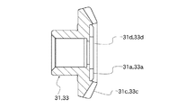
前進ギア31と後退ギア33は、図3〜図5に示すように、一方の側面の外周側に駆動ギア23から駆動力が入力される入力ギア31c、33cを有し、入力ギア31c、33cより径方向内側にドッグギア35と対向して噛合可能な噛合部31d、33dを備えている。この前進ギア31と後退ギア33は、出力軸29の周囲に出力軸29に接合されることなく、それぞれケーシング14に固定された軸受け26により回転自在に保持されている。そして、これらの前進ギア31及び後退ギア33には、駆動軸21の駆動ギア23が常時噛合されており、駆動軸21の回転により、常時互いに反対方向に駆動されるようになっている。
As shown in FIGS. 3 to 5, the
ドッグギア35は、図6〜図9に示すように、前進ギア31と後退ギア33との間の出力軸29の周囲に配置され、両側面に前進ギア31及び後退ギア33と対向して噛合可能な噛合部35dを有する略円筒形状を有し、内周面には軸方向にスプライン歯35cが設けられている。
As shown in FIGS. 6 to 9, the
このドッグギア35は、ドッグギア35の軸方向に設けられたスプライン歯35cが出力軸29に軸方向に設けられたスプライン歯29aに結合されるとともに、後述する切換え機構41の固定ピン34が出力軸29の軸方向に形成された長孔29bとドッグギア35の相通孔35fとに挿通されて、周囲からコイルバネ28で係止されることにより、出力軸29に対して軸方向に移動可能に連結されている。
In the
また、このドッグギア35は、そのスプライン歯35cが出力軸29に設けられた軸方向のスプライン歯29aに結合されることにより、出力軸29に対して周方向に回転不能に連結されている。
The
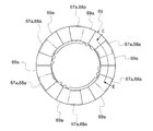
そして、前進ギア31及び後退ギア33の噛合部31d、33dには、図5に示すような複数の噛合凸部31a、33aが周方向に均等に配設されており、一方、ドッグギア35の噛合部35dには、図9に示すような噛合凹部36aが、噛合凸部31a、33aと同ピッチで配設されている。
The meshing
これらの噛合凸部31a、33a及び噛合凹部36aは、入力ギア31c、33cより内側であって、出力軸29より外側の範囲に設けられており、その範囲としては、例えば、出力軸29の軸心廻りの半径20〜32mmの範囲とするのが好適である。この範囲の最小半径が小さ過ぎると、出力軸29の直径が不足して、300PS以上のエンジンによる駆動力に対する強度が不足し易くなる。一方、最大半径が大きすぎると前進ギア31及び後退ギア33の入力ギア31c、33cの外径が大きくなるため、クラッチ装置25が肥大化して船外機10が大型化し易い。
These meshing
また、300PS以上のエンジンにより駆動される場合、噛合凸部31a、33a及び噛合凹部36aは、それぞれ少なくとも7個設けられることが必要であり、好ましくは、10個以下とするのが好適である。噛合凸部31a、33a及び噛合凹部36aが多過ぎると、噛合い時の噛合い衝突が増加し、好ましくない。好ましくは、これらの噛合凸部31a、33a及び噛合凹部36aの数は8個乃至10個、特に好ましくは、この実施の形態のようにそれぞれ9個設けられることが好適である。
Further, when driven by an engine of 300 PS or more, it is necessary that at least 7 meshing
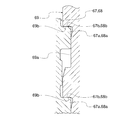
これらの前進ギア31及び後退ギア33の各噛合凸部31a、33aの駆動方向前方側には、ドッグギア35の噛合時に、ドッグギア35の噛合凹部36aと周方向に対向して当接する駆動力伝達面31b、33bを有し、一方、ドッグギア35の各噛合凹部36aの駆動方向後方側には、前進ギア31及び後退ギア33との噛合時に、前進ギア31及び後退ギア33の各噛合凸部31a、33aと周方向に対向して当接する駆動力伝達面35bを有している。
A driving force transmission surface that faces the
このクラッチ装置25では、前進ギア31の噛合部31dにおける全ての噛合凸部31aの駆動力伝達面31bの面積の合計、及び、前進ギア31の噛合部31dと噛合するドッグギア35の噛合部35dにおける全ての噛合凹部36aの駆動力伝達面35bの面積の合計が340mm2以上となっていることが好ましく、更に好ましくは、394.625mm2以上であることが好適である。
In this
また。後退ギア33の噛合部33dにおける全ての噛合凸部33aの駆動力伝達面33bの面積の合計、及び、後退ギア33の噛合部33dと噛合するドッグギア35の噛合部35dにおける全ての噛合凹部36aの駆動力伝達面35bの面積の合計が340mm2以上となっていることが好ましく、更に好ましくは、394.625mm2以上であることが好適である。
Also. The sum of the areas of the driving force transmission surfaces 33b of all the meshing
ここでは、前進ギア31の駆動力伝達面31bの面積の合計及び前進ギア31側の駆動力伝達面35bの面積の合計か、後退ギア33の駆動力伝達面33bの面積の合計及び後退ギア33側の駆動力伝達面35bの面積の合計かの一方がこの面積以上であってもよいが、好ましくは、両方がこの面積以上であることが好適である。
Here, the total area of the driving
駆動力伝達面31b、駆動力伝達面33b、駆動力伝達面35bがこのような範囲であれば、前進ギア31又は後退ギア33とドッグギア35との噛合状態で、伝達トルクを十分に分散することができ、噛合凸部や噛合凹部の破損をより防止し易いからである。
If the driving
また、このクラッチ装置25では、噛合凸部31a、33a及び噛合凹部36aは、それぞれ出力軸29の軸心を中心に40度のピッチθ1で形成されており、各噛合凸部31a、33a及び噛合凹部36aの周方向長さは出力軸29の軸心を中心にした角度で12度〜23度の範囲に形成されている。この範囲であれば、300PS以上のエンジンによる駆動力に対する強度を確保し易いからである。
Further, in this
その場合、噛合凸部31a、33aは噛合凹部36aより周方向長さが出力軸29の軸心を中心にした角度で1度〜12度小さく形成されることが好ましい。噛合い易さのためである。更に、ここでは、40度のピッチと噛合凸部31a、33aの周方向長さとの差θ2を20度以上確保することが特に好ましい。これにより噛合凸部と噛合凹部とを確実に嵌合し易くできるからである。
In that case, it is preferable that the meshing
更に、このクラッチ装置25では、各駆動力伝達面31b、33bのドッグギア35側となる外側端縁31g、33gと、ドッグギア35の前進ギア31側の各駆動力伝達面35bの前進ギア31側となる外側端縁35gと、ドッグギア35の後退ギア33側の各駆動力伝達面35bの後退ギア33側となる外側端縁35gとが、全て出力軸29の軸方向に対して直交方向に沿う直線状に形成されている。
Further, in this
ここでは、前進ギア31の噛合部31dにおける全ての駆動力伝達面31bの外側端縁31gの長さの合計、及び、前進ギア31の噛合部31dと噛合するドッグギア35の噛合部35dにおける全ての駆動力伝達面35bの外側端縁35gの長さの合計が、70mm以上となっていることが好ましく、更に好ましくは71.75mm以上であることが好適である。
Here, the sum of the lengths of the outer end edges 31g of all the driving force transmission surfaces 31b in the meshing
後退ギア33の噛合部33dにおける全ての駆動力伝達面33bの外側端縁33gの長さの合計、及び、後退ギア33の噛合部33dと噛合するドッグギア35の噛合部35dにおける全ての駆動力伝達面35bの外側端縁35gの長さの合計が、70mm以上となっていることが好ましく、更に好ましくは71.75mm以上であることが好適である。
The total length of the
ここでは、前進ギア31の駆動力伝達面31bの外側端縁31gの合計及び前進ギア31側の駆動力伝達面35bの外側端縁35gの長さの合計か、後退ギア33の駆動力伝達面33bの外側端縁33gの長さの合計及び後退ギア33側の駆動力伝達面35bの外側端縁35gの長さの合計かの一方がこの長さ以上であってもよく、両方であってもよい。好ましくは、両方がこの長さ以上であることが好適である。
Here, the total of the
駆動力伝達面31b、駆動力伝達面33b、駆動力伝達面35bの長さの合計がこのような範囲であれば、前進ギア31又は後退ギア33とドッグギア35との噛合時に、駆動力伝達面31b、33b、35bの外側端縁31g、33g、35g近傍同士が当接した際の衝撃を分散することができる。
If the total length of the driving
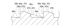
また、このクラッチ装置25では、隣接する噛合凹部36a間の噛合凸部である頂部37a、即ち、各噛合凹部36aの駆動方向前方側の頂部37aに、後壁部35eまで達するスロープ37bが設けられている。このスロープ37bは噛合凹部36aの駆動方向前方側に駆動方向に沿って深くなるように形成されている。なお、頂部37aのスロープ37b以外の部分は出力軸29の軸心と直交する平面に形成されている。
Further, in this
このようにすれば、噛合凸部31a、33a及び噛合凹部36aをそれぞれ7個以上設けることでピッチθ1が小さくなり、噛合し難くなっていても、噛合凸部31a、33aが噛合凹部36aに隣接する頂部に圧接されて、スロープ37b上を摺動することで、その噛合凹部36aに嵌合し易くなるからである。
In this way, by providing seven or more meshing
このスロープ37bは、図9に示すように各噛合凹部36aの駆動方向前方端部の底部36bから延びる仮想平面37cと一致するように形成することが好ましい。スロープ37bを加工し易いからである。
As shown in FIG. 9, the
このクラッチ装置25は、ドッグギア35が固定ピン34に連結された切換え機構41により軸方向に移動可能に構成されている。
The
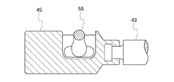
この切換え機構41は、図2及び図10〜図12に示すように、出力軸29のプロペラ27とは反対側の端部の中心部に配置され、固定ピン34と連結された軸方向に移動可能なシフトプランジャ43と、このシフトプランジャ43の端部に接合されたシフト従動体45と、このシフト従動体45をケーシング14の上部から軸方向に操作するためのシフトロッド47と、このシフトロッド47の上部に固定されてシフトロッド47を回動させるためのシフトレバー49とを有している。
As shown in FIGS. 2 and 10 to 12, the
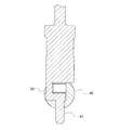
シフトプランジャ43には、位置決め用ボール51がバネ部材53により直径方向に付勢された状態で配置されており、ドッグギア35が前進ギア31又は後退ギア33と噛合しない位置で位置決め用ボール51が出力軸29の被係止部29cに係止できる構成となっている。
A
また、図11及び図12に示すように、シフトロッド47の下端近傍には、シフトロッド47の軸から偏心してシフト従動体45と連結したカム部55が設けられている。一方、シフト従動体45のカム部55との連結部位には、カム部55が摺動可能な横溝57が設けられている。そのため、シフトロッド47が回動されてカム部55がシフトロッド47の軸を中心に揺動すると、カム部55が横溝57を押圧して、シフト従動体45とシフトプランジャ43とが軸方向に移動し、ドッグギア35が軸方向に移動可能となっている。
Further, as shown in FIGS. 11 and 12, a
このような構成のクラッチ装置25を有する船外機10では、エンジンにより駆動軸21が回転すると、駆動ギア23により前進ギア31及び後退ギア33が互いに逆方向に回転駆動される。そして、シフトレバー49によりシフトロッド47を前進となる一方側に回動させると、シフトロッド47のカム部55が揺動してシフト従動体45の横溝57を一方側に押圧することにより、シフト従動体45及びシフトプランジャ43が出力軸29の軸方向の端部側へ移動する。
In the
すると、シフトプランジャ43に連結されている固定ピン34を介して、ドッグギア35が出力軸29の軸方向の端部側に移動し、ドッグギア35の一方の噛合部35dが前進ギア31に噛合する。
Then, the
このとき、前進ギア31はエンジンの回転数に応じた回転速度で回転しているが、出力軸29及びドッグギア35は停止状態等、前進ギア31とは異なる回転速度となっている。即ち、噛合凸部31aが噛合凹部36aより速い速度で移動している。そのため、噛合凹部36aが噛合凸部31aに対向する位置においてドッグギア35が軸方向に充分に速い移動速度で挿入されれば、噛合凹部36aが直接、噛合凸部31aに嵌合されることができるが、通常は、ドッグギア35を軸方向に移動させると、図13(a)から(e)に示すように、隣接する噛合凹部36a間が噛合凸部31aの頂面に当接して嵌合されることになる。
At this time, the
まず、図13(a)に示すように、噛合凸部31aが矢印X方向に移動している状態で、停止状態の噛合凹部36aを矢印Y方向に移動させると、噛合凸部31aの頂面31eに噛合凹部36a間の頂部37aが圧接され、(b)に示すように、頂部37aが噛合凸部31aの頂面31e上で摺動してスロープ37bに到達する。ここでスロープ37bの形状に沿って移動し、(c)に示すように、噛合凹部36aが噛合凸部31a側に案内される。そして、噛合凹部36aが噛合凸部31aの位置に達すると、(d)に示すように、噛合凹部36aの駆動力伝達面35bの先端部分が噛合凸部31aの駆動力伝達面31bの外側端縁に当接し、噛合凹部36a内の所定位置に噛合凸部31aが配置される。その後、(e)に示すように、噛合凹部36a内に噛合凸部31aが嵌合され、両者の駆動力伝達面31b、35b同士が確実に当接されてドッグギア35と前進ギア31とが噛合される。
First, as shown in FIG. 13 (a), when the meshing
このようにしてドッグギア35と前進ギア31とが噛合されると、駆動軸21からの駆動力が前進ギア31を介してドックギア35に伝達され、ドッグギア35のスプライン歯35cにより出力軸29に伝達されて、出力軸29及びこの出力軸29に連結されているプロペラ27を前進方向に回転させることができる。
When the
なお、後退する場合には、シフトレバー49によりシフトロッド47を反対方向に回動させ、シフトロッド47のカム部55により、シフト従動体45及びシフトプランジャ43を反対方向に移動させ、ドッグギア35を出力軸29のプロペラ27側へ移動させることにより、前記と同様にしてドッグギア35と後退ギア33とを噛合させればよい。
When reversing, the
以上のような構成のクラッチ装置25を有する船外機10によれば、ドッグギア35と各前進ギア31及び後退ギア33との互いに対向する各噛合部31d、33d、35dでは、噛合凸部31a、33a及び噛合凹部36aが入力ギア31c、33cより径方向内側に配置されているので、噛合凸部31a、33a及び噛合凹部36aとが、入力ギア31c、33cと出力軸29との間の限られた空間に配置されている。そのため、噛合凸部31a、33a及び噛合凹部36aの大きさが著しく制限されている。
According to the
ところが、このような限られた空間内であっても、噛合凸部31a、33a及び噛合凹部36aを周方向にそれぞれ7個以上設け、噛合時に噛合凸部31a、33aと噛合凹部36aとの互いに周方向に対向する駆動力伝達面31b、33b、35bのそれぞれに伝達トルクを分散するように構成されているので、300PS以上の最大出力を有する駆動部から大きな駆動力を出力軸29に伝達される場合であっても、噛合させる際や噛合状態で駆動力を伝達する際に、噛合凸部31a、33aや噛合凹部36aに潰れ、割れ、変形等の破損が生じることを防止することができる。例えば、クラッチ装置25の伝達トルクが60kg・m以上であっても十分に破損を防止することが可能である。
However, even in such a limited space, seven or more meshing
なお、上記実施の形態は、この発明の範囲内において、適宜変更可能である。例えば、上記では、ドッグギア35だけにスロープ37bを設けた例について説明したが、前進ギア31及び後退ギア33にスロープを設けてもよく、前進ギア31及び後退ギア33並びにドッグギア35にスロープを設けることも可能である
The above-described embodiment can be appropriately changed within the scope of the present invention. For example, in the above description, the example in which the
10 船外機
21 駆動軸
23 駆動ギア
25 クラッチ装置
29 出力軸
31 前進ギア
31a 噛合凸部
31b 駆動力伝達面
31c、33c 入力ギア
31d 噛合部
31g 外側端縁
33 後退ギア
33a 噛合凸部
33b 駆動力伝達面
33d 噛合部
33g 外側端縁
35 ドッグギア
35b 駆動力伝達面
35d 噛合部
36a 噛合凹部
37b スロープ
DESCRIPTION OF
Claims (5)
前記駆動軸の下端側に当該駆動軸と一体に回転可能に配設された駆動ギアと、
前記ケーシングの下部に配設され、前記駆動ギアと連結されたクラッチ装置と、
前記クラッチ装置に連結され、プロペラを駆動する出力軸と、を備え、
前記クラッチ装置は、
前記プロペラを駆動する前記出力軸の周囲に回転自在に配置され、前記駆動部で駆動される前記駆動軸により常時反対方向に駆動される一対の前進ギア及び後退ギアと、
前記出力軸の周囲の前記前進ギアと前記後退ギアとの間に配置され、前記出力軸に対して軸方向に移動可能、且つ、周方向に回転不能なドッグギアとを備え、
前記前進ギア及び前記後退ギアの前記ドッグギアと対向する部位と、前記ドッグギアの前記前進ギア及び前記後退ギアとそれぞれ対向する部位とに設けられた噛合部に、それぞれ互いに嵌合可能な噛合凸部及び噛合凹部が複数設けられ、
前記ドッグギアが前記出力軸に対して一方の軸方向に移動させられて、前記複数の噛合凹部と前記複数の噛合凸部とが嵌合することにより、前記ドッグギアと前記前進ギア又は前記後退ギアの一方とが噛合し、前記出力軸が駆動されるように構成されており、
前記駆動軸は、前記出力軸側に固定された前記駆動ギアを回転させるものであり、
前記前進ギア及び前記後退ギアは、前記駆動ギアと常時噛合された入力ギアをそれぞれ備え、
前記噛合凸部及び前記噛合凹部は、前記入力ギアより径方向内側の範囲で、それぞれ周方向に7個以上10個以下配設されていることを特徴とする船外機。 A drive unit mounted on an upper portion of the casing, and a drive shaft driven by the drive unit;
A drive gear disposed on the lower end side of the drive shaft so as to be rotatable integrally with the drive shaft;
A clutch device disposed at a lower portion of the casing and connected to the drive gear;
An output shaft coupled to the clutch device and driving a propeller,
The clutch device is
A pair of forward gears and reverse gears that are rotatably arranged around the output shaft that drives the propeller, and are always driven in opposite directions by the drive shaft driven by the drive unit;
A dog gear that is disposed between the forward gear and the reverse gear around the output shaft, is movable in the axial direction with respect to the output shaft, and is not rotatable in the circumferential direction;
Engaging protrusions that can be fitted to each other at meshing portions provided at portions of the forward gear and the reverse gear facing the dog gear and portions of the dog gear facing the forward gear and the reverse gear, respectively. A plurality of meshing recesses are provided,
The dog gear is moved in one axial direction with respect to the output shaft, and the plurality of meshing recesses and the plurality of meshing projections are fitted, whereby the dog gear and the forward gear or the reverse gear are One is meshed, and the output shaft is configured to be driven,
The drive shaft rotates the drive gear fixed to the output shaft side,
The forward gear and the reverse gear each include an input gear that is always meshed with the drive gear,
The outboard motor, wherein the meshing convex portion and the meshing concave portion are arranged in the circumferential direction in the range of 7 to 10 in the radial direction from the input gear.
前記各噛合部の前記外側端縁の長さの合計がそれぞれ70mm以上であることを特徴とする請求項1乃至3の何れか一つに記載の船外機。 In each meshing portion between the forward gear and the dog gear or each meshing portion between the reverse gear and the dog gear, the outer edge of each driving force transmission surface is orthogonal to the axial direction of the output shaft. Formed in a straight line along the direction,
The outboard motor according to any one of claims 1 to 3, wherein the total length of the outer end edges of the respective meshing portions is 70 mm or more.
Priority Applications (1)
| Application Number | Priority Date | Filing Date | Title |
|---|---|---|---|
| JP2012069479A JP2012159196A (en) | 2012-03-26 | 2012-03-26 | Outboard motor |
Applications Claiming Priority (1)
| Application Number | Priority Date | Filing Date | Title |
|---|---|---|---|
| JP2012069479A JP2012159196A (en) | 2012-03-26 | 2012-03-26 | Outboard motor |
Related Parent Applications (1)
| Application Number | Title | Priority Date | Filing Date |
|---|---|---|---|
| JP2007031053A Division JP4979405B2 (en) | 2007-02-09 | 2007-02-09 | Outboard motor |
Publications (1)
| Publication Number | Publication Date |
|---|---|
| JP2012159196A true JP2012159196A (en) | 2012-08-23 |
Family
ID=46839895
Family Applications (1)
| Application Number | Title | Priority Date | Filing Date |
|---|---|---|---|
| JP2012069479A Withdrawn JP2012159196A (en) | 2012-03-26 | 2012-03-26 | Outboard motor |
Country Status (1)
| Country | Link |
|---|---|
| JP (1) | JP2012159196A (en) |
Cited By (1)
| Publication number | Priority date | Publication date | Assignee | Title |
|---|---|---|---|---|
| TWI608962B (en) * | 2016-01-27 | 2017-12-21 | Solas Science & Engineering Co Ltd | Double-piece shaft sleeve for marine propeller and marine propeller using the same |
Citations (8)
| Publication number | Priority date | Publication date | Assignee | Title |
|---|---|---|---|---|
| JPS5381756U (en) * | 1976-12-09 | 1978-07-06 | ||
| JPS57204322A (en) * | 1981-06-11 | 1982-12-15 | Yamaha Motor Co Ltd | Forward/backward motion changeover device for ship propeller |
| JPS57204324A (en) * | 1981-06-11 | 1982-12-15 | Yamaha Motor Co Ltd | Forward/backward motion changeover device for ship propeller |
| JPS5973627A (en) * | 1982-10-16 | 1984-04-25 | Sanshin Ind Co Ltd | Dog clutch |
| JPH05196058A (en) * | 1991-10-18 | 1993-08-06 | Kaaz Corp | Claw form of claw clutch |
| JPH09195830A (en) * | 1996-01-12 | 1997-07-29 | Yamaha Motor Co Ltd | Method for controlling air/fuel ratio for internal combustion engine |
| JP2005048820A (en) * | 2003-07-31 | 2005-02-24 | Yamaha Marine Co Ltd | Clutch device for outboard engine |
| JP2005535838A (en) * | 2002-06-19 | 2005-11-24 | アステリカ リミテッド | Connection device between machine parts |
-
2012
- 2012-03-26 JP JP2012069479A patent/JP2012159196A/en not_active Withdrawn
Patent Citations (8)
| Publication number | Priority date | Publication date | Assignee | Title |
|---|---|---|---|---|
| JPS5381756U (en) * | 1976-12-09 | 1978-07-06 | ||
| JPS57204322A (en) * | 1981-06-11 | 1982-12-15 | Yamaha Motor Co Ltd | Forward/backward motion changeover device for ship propeller |
| JPS57204324A (en) * | 1981-06-11 | 1982-12-15 | Yamaha Motor Co Ltd | Forward/backward motion changeover device for ship propeller |
| JPS5973627A (en) * | 1982-10-16 | 1984-04-25 | Sanshin Ind Co Ltd | Dog clutch |
| JPH05196058A (en) * | 1991-10-18 | 1993-08-06 | Kaaz Corp | Claw form of claw clutch |
| JPH09195830A (en) * | 1996-01-12 | 1997-07-29 | Yamaha Motor Co Ltd | Method for controlling air/fuel ratio for internal combustion engine |
| JP2005535838A (en) * | 2002-06-19 | 2005-11-24 | アステリカ リミテッド | Connection device between machine parts |
| JP2005048820A (en) * | 2003-07-31 | 2005-02-24 | Yamaha Marine Co Ltd | Clutch device for outboard engine |
Cited By (1)
| Publication number | Priority date | Publication date | Assignee | Title |
|---|---|---|---|---|
| TWI608962B (en) * | 2016-01-27 | 2017-12-21 | Solas Science & Engineering Co Ltd | Double-piece shaft sleeve for marine propeller and marine propeller using the same |
Similar Documents
| Publication | Publication Date | Title |
|---|---|---|
| EP3734113A1 (en) | Apparatus for driving electric vehicle and method of controlling the same | |
| JP5956805B2 (en) | transmission | |
| JP4979405B2 (en) | Outboard motor | |
| CN102537308A (en) | Gear shift device | |
| JP2007078134A (en) | Driving force distribution device | |
| EP3214341B1 (en) | Transmission | |
| JP2012159196A (en) | Outboard motor | |
| EP3327305B1 (en) | Transmission | |
| JP2012026480A (en) | Shift device of transmission for vehicle | |
| EP3760897A1 (en) | Outboard motor | |
| JP6590569B2 (en) | transmission | |
| JP2000249162A (en) | Engaging clutch | |
| JP6494949B2 (en) | Power transmission device for hybrid vehicle | |
| WO2019225818A1 (en) | Cycloidal speed reducer | |
| JP6503067B2 (en) | transmission | |
| JP6248507B2 (en) | Dog clutch type transmission | |
| JP2017096403A (en) | Transmission of vehicle | |
| KR101510968B1 (en) | Synchronizer for manual transmission | |
| JP6150588B2 (en) | Intermittent transmission | |
| JP2010185560A (en) | Gear transmission | |
| JP2018165527A (en) | Variable speed pulley support device for belt type continuously variable transmission | |
| JP6236476B2 (en) | Abnormal noise reduction device for transmission | |
| JP2019105336A (en) | Dog clutch and transmission | |
| JP2007051668A (en) | Differential device | |
| JP2018054037A (en) | Differential device |
Legal Events
| Date | Code | Title | Description |
|---|---|---|---|
| A977 | Report on retrieval |
Free format text: JAPANESE INTERMEDIATE CODE: A971007 Effective date: 20130322 |
|
| A131 | Notification of reasons for refusal |
Free format text: JAPANESE INTERMEDIATE CODE: A131 Effective date: 20130326 |
|
| A761 | Written withdrawal of application |
Free format text: JAPANESE INTERMEDIATE CODE: A761 Effective date: 20130402 |
|
| A521 | Written amendment |
Free format text: JAPANESE INTERMEDIATE CODE: A523 Effective date: 20130415 |
|
| A521 | Written amendment |
Free format text: JAPANESE INTERMEDIATE CODE: A821 Effective date: 20130415 |