EP3760827B1 - Ladder - Google Patents
Ladder Download PDFInfo
- Publication number
- EP3760827B1 EP3760827B1 EP20189923.4A EP20189923A EP3760827B1 EP 3760827 B1 EP3760827 B1 EP 3760827B1 EP 20189923 A EP20189923 A EP 20189923A EP 3760827 B1 EP3760827 B1 EP 3760827B1
- Authority
- EP
- European Patent Office
- Prior art keywords
- ladder
- assembly
- rung
- displaceable member
- displaceable
- Prior art date
- Legal status (The legal status is an assumption and is not a legal conclusion. Google has not performed a legal analysis and makes no representation as to the accuracy of the status listed.)
- Active
Links
- 230000007246 mechanism Effects 0.000 claims description 50
- 238000006073 displacement reaction Methods 0.000 claims description 6
- 230000000712 assembly Effects 0.000 description 13
- 238000000429 assembly Methods 0.000 description 13
- 238000000034 method Methods 0.000 description 7
- 230000008878 coupling Effects 0.000 description 5
- 238000010168 coupling process Methods 0.000 description 5
- 238000005859 coupling reaction Methods 0.000 description 5
- 239000000463 material Substances 0.000 description 5
- 230000008901 benefit Effects 0.000 description 3
- 229920003023 plastic Polymers 0.000 description 3
- 239000004033 plastic Substances 0.000 description 3
- GVGLGOZIDCSQPN-PVHGPHFFSA-N Heroin Chemical compound O([C@H]1[C@H](C=C[C@H]23)OC(C)=O)C4=C5[C@@]12CCN(C)[C@@H]3CC5=CC=C4OC(C)=O GVGLGOZIDCSQPN-PVHGPHFFSA-N 0.000 description 2
- 239000002131 composite material Substances 0.000 description 2
- 238000004519 manufacturing process Methods 0.000 description 2
- 229910000838 Al alloy Inorganic materials 0.000 description 1
- 244000025254 Cannabis sativa Species 0.000 description 1
- 206010017577 Gait disturbance Diseases 0.000 description 1
- 230000009471 action Effects 0.000 description 1
- 230000001154 acute effect Effects 0.000 description 1
- 239000000853 adhesive Substances 0.000 description 1
- 230000001070 adhesive effect Effects 0.000 description 1
- 229910052782 aluminium Inorganic materials 0.000 description 1
- XAGFODPZIPBFFR-UHFFFAOYSA-N aluminium Chemical compound [Al] XAGFODPZIPBFFR-UHFFFAOYSA-N 0.000 description 1
- 230000003466 anti-cipated effect Effects 0.000 description 1
- 238000005219 brazing Methods 0.000 description 1
- 230000001419 dependent effect Effects 0.000 description 1
- 230000000694 effects Effects 0.000 description 1
- 239000011152 fibreglass Substances 0.000 description 1
- 230000005484 gravity Effects 0.000 description 1
- 229910052751 metal Inorganic materials 0.000 description 1
- 239000002184 metal Substances 0.000 description 1
- 229910001092 metal group alloy Inorganic materials 0.000 description 1
- 150000002739 metals Chemical class 0.000 description 1
- 238000012986 modification Methods 0.000 description 1
- 230000004048 modification Effects 0.000 description 1
- 229920000642 polymer Polymers 0.000 description 1
- 239000002861 polymer material Substances 0.000 description 1
- 230000001953 sensory effect Effects 0.000 description 1
- 238000003860 storage Methods 0.000 description 1
- 238000003466 welding Methods 0.000 description 1
- 239000002023 wood Substances 0.000 description 1
Images


Classifications
-
- E—FIXED CONSTRUCTIONS
- E06—DOORS, WINDOWS, SHUTTERS, OR ROLLER BLINDS IN GENERAL; LADDERS
- E06C—LADDERS
- E06C7/00—Component parts, supporting parts, or accessories
- E06C7/003—Indicating devices, e.g. user warnings or inclinators
-
- E—FIXED CONSTRUCTIONS
- E06—DOORS, WINDOWS, SHUTTERS, OR ROLLER BLINDS IN GENERAL; LADDERS
- E06C—LADDERS
- E06C7/00—Component parts, supporting parts, or accessories
- E06C7/08—Special construction of longitudinal members, or rungs or other treads
-
- E—FIXED CONSTRUCTIONS
- E06—DOORS, WINDOWS, SHUTTERS, OR ROLLER BLINDS IN GENERAL; LADDERS
- E06C—LADDERS
- E06C1/00—Ladders in general
- E06C1/02—Ladders in general with rigid longitudinal member or members
- E06C1/14—Ladders capable of standing by themselves
- E06C1/16—Ladders capable of standing by themselves with hinged struts which rest on the ground
- E06C1/18—Ladders capable of standing by themselves with hinged struts which rest on the ground with supporting struts formed as ladders
Definitions
- Ladders are conventionally utilized to provide a user thereof with improved access to elevated locations that might otherwise be inaccessible.
- Ladders come in many shapes and sizes, such as straight ladders, straight extension ladders, stepladders, and combination step and extension ladders. So-called combination ladders may incorporate, in a single ladder, many of the benefits of various ladder designs.
- Ladders known as step ladders are self-supporting ladders, meaning that they do not need to be leaned against a wall, pole or other structure for stability. Rather, step ladders may be positioned on a floor (or other similar surface) such that at least three feet of the ladder, and conventionally four feet, provide a stable support structure for a user to climb upon, even in an open space (e.g., outside or in the middle of a room) without a wall, roof, pole or other type of structure being necessary for the stability of the ladder.
- Conventional step ladders may include a first rail assembly coupled with a top cap and a second rail assembly coupled with the top cap.
- One of the rail assemblies conventionally includes a plurality of rungs that are evenly spaced between the supporting surface (e.g., the floor or ground) and the top cap.
- a ladder can present various risks to the user. For example, one potential hazard exists where a user is distracted or is not paying attention and loses track of which rung they are currently standing on - particularly when they are descending the ladder. In such a case, a user may think, for example, that their next "step” downward will place them on the ground at the bottom of the ladder when, in reality, there is still one more step for them to descend prior to reaching the ground. This misperception can result in the user stumbling on, or even missing completely, the lowest rung of the ladder. There is a continuing desire in the industry to provide ladders that reduce the risk of accident and provide improved safety and stability to a user thereof.
- US 6578663 discloses a ladder including a rung, an overlap step and an alarm coupled with the rung, the alarm comprising a spring-loaded keeper catch pin operative to mechanically create an audible alarm when pressure is applied to displace the overlap step relative to the run, the audible alarm being generated by a stepped inner surface of the overlap step sliding over a leading end of the spring-loaded keeper catch pin.
- the ladder may comprise a plurality of additional rungs extending between and coupled to the first pair of spaced apart rails.
- the rung assembly is positioned to act as the lowermost rung of the step ladder.
- an upper tread portion of the displaceable member is substantially coplanar with the upper wall of the base member.
- the at least one alert mechanism includes a pin, a collar slidably disposed about the pin, and a detent mechanism configured to hold the collar at a specified position on the pin until a force of a specified magnitude is applied to the collar.
- the at least one alert mechanism may be positioned and configured so that the detent mechanism releases the collar when the displaceable mechanism is in the first position.
- the at least one alert mechanism includes two alert mechanisms.
- the ladder further comprises a second assembly having at least one rail and a top cap coupled to the first assembly and to the second assembly.
- the stepladder 100 includes a first assembly 102 having a pair of spaced apart rails 104 and a plurality of rungs 106 extending between, and coupled to, the rails 104.
- the spaced apart rungs 106 are substantially parallel to one another and are configured to be substantially level when the stepladder 100 is in an orientation for intended use, so that they may be used as "steps" for a user to ascend the stepladder 100 as will be appreciated by those of ordinary skill in the art.
- the lowermost rung comprises a rung assembly 106A as will be described in further detail below with reference to FIGS. 10-13 .
- other rungs e.g., second lowest rung, top rung, or all rungs
- the stepladder 100 also includes a second assembly 108 having a pair of spaced apart rails 110.
- the second assembly 108 need not include a plurality of rungs between the spaced apart rails 110. Rather, bracing or other structural components may be used to provide a desired level of rigidity and strength to the spaced apart rails 110.
- the second assembly 108 may include rungs configured generally similar to those associated with the first assembly 102. The second assembly 108, thus, may be used to help support the stepladder 100 when in an intended operational state, such as generally depicted in FIG. 1 .
- the first and second assemblies 102 and 108 may be formed of a variety of materials and using a variety of manufacturing techniques.
- the rails 104 and 110 may be formed of a composite material, such as fiberglass, while the rungs and other structural components may be formed of aluminum or an aluminum alloy.
- the assemblies 102 and 108 (and their various components) may be formed of other materials including other composites, plastics, polymers, metals, metal alloys or combinations of such materials.
- a top cap 112 is coupled to a portion of the first assembly 102 and a portion of the second assembly.
- the top cap 112 may be pivotally coupled to an upper end of the each rail 104 of the first assembly 102 along a common axis.
- the top cap 112 is also pivotally coupled to an upper end of each rail 110 of the second assembly 108 along another common axis.
- upper end merely refers to a relative position of the described components when the stepladder 100 is in an orientation of intended use orientation.
- the top cap 112 may simply be a structural component configured to facilitate relative coupling of the first and second assemblies 102 and 108.
- the top cap may include features that enable it to be used as a tray or a tool holder.
- the top cap 112 may be used to organize a user's tools, supplies and other resources while working on the stepladder 100.
- a top cap is described in U.S. Patent No. 8,186, 481 issued May 29, 2012 and entitled LADDERS, LADDER COMPONENTS AND RELATED METHODS. It is noted that, for safety purposes, the top cap 112 is not conventionally configured as a "rung” or a "step” and may not necessarily be designed to support a user's full weight.
- the top cap 112 may be formed from a variety of materials. In one embodiment, the top cap 112 may be formed from a plastic material that is molded into a desired size and shape.
- the stepladder 100 may additionally include a plurality of feet 114 (one associated with each rail) configured to engage a supporting surface such as the ground.
- the feet 114 may be configured in a variety of manners based on, for example, the type of environment in which the ladder is anticipated to be used.
- the feet may be formed of a plastic or polymer material and can be configured with a plurality of ridges, knobs or other features configured to provided increased friction between the ladder and a relatively rigid supporting surface (e.g., concrete, tile or wood).
- the feet 114 may be configured with barbs or other sharp protrusions configured to dig into a relatively softer supporting surface (e.g., dirt or grass).
- a pair of hinged braces referred to herein as spreaders 120, are used to maintain a desired angle between the first and second assemblies 102 and 108 when the stepladder 100 is in a deployed or useable state.
- the hinged nature of such spreaders 120 helps to enable the first and second assemblies 102 and 108 to collapse into a stored state and then help lock the assemblies 102 and 108 in position relative to one another when in a deployed or useable state.
- the spreaders 120 are not configured as rungs or platforms, or otherwise configured to support a user standing thereon. Rather, the spreaders 120 are simply configured to structurally maintain the ladder 100 in a deployed position while enabling the rail assemblies to be selectively collapsed relative to each other for storage and transportation of the ladder 100.
- a first rung assembly 106A including a base member 140 that is configured for substantially rigid coupling with the rails 104 of the first assembly 102 of a ladder 100.
- the base member 140 includes a front wall 142, a rear wall 144, and an upper wall 146 extending between and coupled with the front and rear walls 142 and 144.
- the various walls 142, 144 and 146 are formed as an integral unit (e.g., welding, brazing, adhesive, mechanical fasteners, etc.).
- the upper wall 146 may or may not include traction features (e.g., ridges and grooves) such as are often found in conventional ladder rungs.
- a groove 148 is formed at, and extends along, the front edge of the upper wall 146.
- the groove 148 may be positioned directly between the upper wall 146 and the front wall 142. In other arrangements, the groove 148 may be formed wholly in the upper wall 146 or wholly in the front wall 142. In other arrangements, rather than a single continuous groove 148 that extends substantially the entire width (i.e., extending between the rails 104 when attached to a ladder) of the base member 140, one or more grooves of shorter dimension may extend partially along the width of the base member 140. In yet other arrangements, the groove 148 could be located along the rear edge of the upper wall 146, reversing the pivoting action of the displaceable member 150 which is described further below.
- the assembly 106A further includes a displaceable member 150 that is coupled with the base member 140.
- the displaceable member includes an upper wall or tread portion 152, which may include one or more traction features 154 (e.g., ridges and grooves).
- the displaceable member 150 may include a rear wall 156 that is configured to extend to, or beyond, the juncture of the rear wall 144 and upper wall 146 of the base member 140.
- the rear wall 156 of the displaceable member may help to prevent the inadvertent pinching of a user's body, the catching of clothing or the entrance of foreign objects between the displaceable member 150 and the base 140.
- the displaceable member 150 may also include a pivot member 158 (or multiple pivot members) disposed within the groove 148 of the base member 140.
- the pivot member 158 may include, for example, an elongated member having a portion thereof that is substantially cylindrical, the pivot member 158 being configured to substantially conform in size and shape with the groove 148. As seen by comparing FIGS. 4 and 5 , the pivot member 158 enables pivoting of the displaceable member 150 relative to the fixed base 140 about an axis extending generally along the front edge of the rung assembly 106A (e.g., along or adjacent an edge where the front wall 142 meets the upper wall 146 of the base 140) and extending between the rails 104 of the ladder 100.
- the "unactuated" or “normal” state of the rung assembly is shown in FIG. 4 , with the displaceable member 150 positioned so that its tread portion or upper wall 152 is at an acute angle relative to the upper wall 146 of the base member 140.
- the upper wall 154 of the displaceable member is pivoted such that it is positioned against and substantially parallel with the upper wall 146 of the base member 140.
- the rung assembly 106A further includes one or more alert mechanisms 170 that, when actuated by displacement of the displaceable member 150 a desired distance (e.g., from the position in FIG. 4 to the position in FIG. 5 ), provides an alert to the user (e.g., by audible noise) informing them that they have stepped on the rung assembly 106A.
- the alert mechanism 170 provides a user with information, as they descend, that they have reached the lowermost rung and that their next step downward will be to the ground or other surface supporting the ladder 100.
- the alert mechanism 170 includes a housing member or a bracket 180 having flange portions of 181 for coupling with the upper wall 146 of the base member 140.
- the bracket 180 includes two walls 182 and 184, each having an opening 186 and 188 formed therein.
- a pin member 190 extends through the openings 186 and 188.
- the pin member 190 includes a shoulder 192 formed along an upper portion thereof and sized to be wider than the opening 186 formed in the upper wall 182.
- the shoulder 192 abuts a biasing member 194 (e.g., a coiled spring or other member) positioned about the pin member 190 between the upper wall 184 and the shoulder 192.
- the shoulder 192 cooperates with the biasing member 194 to retain the pin member 186 within the bracket 180 and also biases the pin 190 upwards relative to the bracket 180.
- a retainer 196 may be coupled to a lower end of the pin member 190 (e.g., a c-clip or snap ring disposed in a groove 198 formed in the pin member) and be configured to abut the lower wall 184 (when displaced towards the lower wall) and retain the pin member 190 within the bracket 180.
- a sleeve or collar 200 is slidably positioned about the pin member 190 between the upper and lower walls 182 and 184.
- a biasing member 202 is positioned about the pin member 190 and located between the collar 200 and the lower wall 184 of the bracket 180 and biases the collar upwards toward the upper wall 182.
- a detent mechanism 204 ( FIGS.
- the detent mechanism 204 may include, for example, a biasing member 206 (e.g., a coiled spring) disposed in a through hole 208 formed in the pin member 190.
- a pair of ball members 210 may be positioned on each side of the biasing member 206 so as to partially protrude from the through hole 208.
- a groove 212 which may correspond generally in size to conform with the radius of the ball members 210, may be formed on the internal surface of the collar 200 such that when the groove 212 is aligned with the ball members 210, the ball members are displaced so as to be partially in the groove 212 and partially in the through hole 208, holding the collar 200 in place relative to the pin member 190.
- the collar 200 remains in the held position relative to the pin member 190 until a force is applied to the collar 200 that is sufficient to overcome the force applied by the biasing member 206 of the detent mechanism 204 (and any friction forces between the ball members 208 and groove of the collar 200), causing the ball members 210 to retract within the through hole 208 and enabling the collar 200 to slide along the length of the pin member 190.
- the alert mechanism 170 when no force is applied to the alert mechanism (beyond the weight of the displaceable member 150), the alert mechanism 170 is in the state as shown in FIG. 6 and the rung assembly 106A is in the state as shown in FIGS. 2 - 4 .
- their weight causes the pin member 190 to be placed downwards (via the pressure applied to the displaceable member 150) as indicated in FIG. 7 .
- This causes the upper biasing member 194 to be compressed between the shoulder 192 and the upper wall 182.
- the detent mechanism 204 holds the collar 200 in position relative to the pin 190 such that the collar 200 is displaced along with the pin member 190 and compresses the lower biasing member 202.
- the lower biasing member 202 causes the collar 200 to slap or smack against the upper wall 182 creating a substantial audible event, alerting the user to the fact that they are standing on the rung assembly 106A.
- the slap or smack of the collar 200 against the upper wall 182 may be of sufficient force to also be felt by a user in addition to being heard.
- the upper biasing member causes the pin member 190 to be displaced upward, causing the displaceable member 150 to be displaced upward (see FIGS. 2 , 4 and 6 ), resetting the detent mechanism 204 within the groove of the collar 200, again holding the collar 200 on the pin member 190 as shown in FIG. 6 .
- two alert mechanisms 170 are shown in FIG. 3 in association with the described arrangement. However, in other arrangements, a single alert mechanism 170 may be used or more than two alert mechanisms may be used.
- the rung assembly 106A includes a base member 240 that is configured for substantially rigid coupling with the rails 104 of the first assembly 102.
- the base member 240 includes a front wall 242, a rear wall 244, and an upper wall 246 extending between and coupled with the front and rear walls 242 and 244.
- the upper wall my include traction features 248 (e.g., ridges and grooves) such as are conventional in traditional ladder rungs.
- the upper wall 246 defines a channel 249 extending across its width.
- a displaceable member 250 is disposed within the channel 249 and configured to be displaced between at least two positions.
- the displaceable member 250 includes an upper wall or surface 252 that may include traction features if desired.
- the base member 240 and the displaceable member 250 may include interlocking flange members, 254 and 256, respectively.
- the interlocking flange members 254 and 256 retain the displaceable member 250 within the channel 249 and define a substantially vertical displacement path for the displacement member 250 relative to the base member 240.
- the rung assembly 106A shown in FIGS. 10-13 may also include one or more alert mechanisms 260 structured similarly to that which has been described above.
- a structural portion 262 of the base member 240 may function similar to the housing or bracket 170 described above (e.g., as an integrated bracket or housing).
- the alert mechanism 260 may include a pin member 190 extending through openings of the structural portion 262, biasing members 194 and 202, collar 200 and a detent mechanism (not shown in FIGS. 10-13 ). The pin member 190 is in abutting contact with the upper wall 252 of the displaceable member 250 so as to be actuated upon displacement of the displaceable member 250.
- the alert mechanism 260 functions substantially similar to that described above with respect to the embodiment shown in FIGS. 6-9 .
- the displaceable member 250 is displaced downwards into the channel 249 until its upper surface is substantially flush or coplanar with the upper surface 246 of the base member 240.
- Displacement of the displaceable member 250 causes the pin member 190 to also be displaced downward.
- the collar 200 is displaced with the pin member 190 until forces of the associated detent mechanism 204 are overcome, causing the collar 200 to be displaced upwards and slap against a surface of the structural portion 262 of the base member 240, alerting a user to the fact that they just stepped on the rung assembly 106A.
- the assembly 106A includes a base member 300 that is configured for substantially rigid coupling with the rails 104 of the first assembly 102.
- the base member 300 includes a front wall 302, a rear wall 304, and an upper wall 306 extending between and coupled with the front and rear walls 302 and 304.
- the upper wall 306 may include traction features 308 (e.g., ridges and grooves) such as are often found in conventional ladder rungs.
- a displaceable member 320 includes an upper surface 322 or a tread member, which may include traction features 324, positioned above the upper wall 306 of the base member 300.
- the upper surface 322 is coupled to two side arms 326.
- the side arms 326 extend through openings 328 formed in the upper wall 306 of the base member 300 and are pivotally coupled to the base member 300 by way of a bracket 330 and pivot member 332.
- a lower portion 334 of the side arms 326 extends beneath the upper wall 306 of the base member 300 and includes a striking portion 336.
- the weight of the user causes the tread or upper surface 322 of the displaceable member 320 to be displaced downward toward the upper wall 306 of the base member 300.
- the side arms 326 pivot relative to the base member 300, as indicated by the directional arrow 340 ( FIG. 15 ).
- the lower portion 334 of the side arms 326 are displaced upwards, as indicated by directional arrow 342, causing the striking portion to strike the upper wall 306 of the base member and create a knocking or ringing sound as an alert to the user that they have stepped on the rung assembly 106A.
- the pivotal side arms function as the alert mechanism in the arrangement shown in FIGS. 14-16 .
- the displaceable member 320 may return to its unactuated position after a user steps off of the rung assembly due to gravity (e.g., a weight associated with the lower portions of the side arms 326) or by way of a biasing member (not shown) associated with the side arms 326 or the treat 322.
- a user when a user stands on the rung assembly 106A (which, in the embodiment shown in FIG. 1 is the lowermost rung of the ladder), they will be alerted by an audible alarm, and in some arrangements, by force feedback (e.g., such as feeling a small slap or knock of the rung from the alert mechanism), - as well as by sensing that there is a different "feel” when standing on the rung assembly as compared to other rungs of the ladder - that they are standing on the lowermost "rung” and recognize that they are only one rung or step above the ground. It is noted that the different "feel" when standing on the rung assembly, event after the alert mechanism has been actuated, may take various different forms.
- the arrangement described with respect to FIGS. 2-5 may include the tread portion residing at a slight angle as compared to other rungs, or it may have a slight rocking feel to it as it rests on the pin members of the alert mechanisms.
- the displaceable member may be configured to protrude slightly from the base member when in the second or actuated position giving a slight "uneven" feel across the surface of the rung.
- a user will send a slight unevenness in the rung as the displaceable member will rest atop the base member when in the actuated position.
- the rung assembly may not be located as the lowermost rung of the ladder.
- it may be located as the second lowermost rung of the ladder, indicating to the user that they still have one more rung to descend prior to reaching the ground.
- the front edge of the rung assembly is not substantially displaced in elevation between the unactuated and actuated states. This includes the arrangement shown in FIGS. 2-5 where the front edge may pivot, but is not substantially displaced in terms of elevation. This provides a positive position of the front edge of the rungs (relative to other components of the ladder, such as the side rails), maintaining the distance between adjacent rungs at their front edges so that the user feels confident as they engage each rung and/or rung assembly. Stated another way, the side front edge of the rung assembly remains at a substantially fixed location on the ladder, even though other components of the rung assembly may be displaced or more relative to, for example, the side rails.
- rung assemblies may be used in other types of ladders, including extension ladders and combination ladders, without limitation.
- extension ladders into which a rung assembly of the present invention may be incorporated are described in U.S. Patent No. 8,365,865 ( U.S. Patent Application No. 12/714,313 filed on Feb. 26, 2010 ) entitled ADJUSTABLE LADDERS AND RELATED METHODS.
- articulating ladders (sometimes referred to as combination ladders) into which a rung assembly of the present invention may be incorporated are described in U.S. Patent No. 7,364,017 ( U.S. Patent Application No. 10/706,308, filed on Nov. 11, 2003 ) entitled COMBINATION LADDERS, LADDER COMPONENTS AND METHODS OF MANUFACTURING SAME
Description
- This application claims priority to provisional application Serial No.
62/049,916, filed September 12, 2014 - Ladders are conventionally utilized to provide a user thereof with improved access to elevated locations that might otherwise be inaccessible. Ladders come in many shapes and sizes, such as straight ladders, straight extension ladders, stepladders, and combination step and extension ladders. So-called combination ladders may incorporate, in a single ladder, many of the benefits of various ladder designs.
- Ladders known as step ladders, sometimes referred to as A-frame ladders, are self-supporting ladders, meaning that they do not need to be leaned against a wall, pole or other structure for stability. Rather, step ladders may be positioned on a floor (or other similar surface) such that at least three feet of the ladder, and conventionally four feet, provide a stable support structure for a user to climb upon, even in an open space (e.g., outside or in the middle of a room) without a wall, roof, pole or other type of structure being necessary for the stability of the ladder. Conventional step ladders may include a first rail assembly coupled with a top cap and a second rail assembly coupled with the top cap. One of the rail assemblies conventionally includes a plurality of rungs that are evenly spaced between the supporting surface (e.g., the floor or ground) and the top cap.
- Regardless of the type of ladder being employed, using a ladder can present various risks to the user. For example, one potential hazard exists where a user is distracted or is not paying attention and loses track of which rung they are currently standing on - particularly when they are descending the ladder. In such a case, a user may think, for example, that their next "step" downward will place them on the ground at the bottom of the ladder when, in reality, there is still one more step for them to descend prior to reaching the ground. This misperception can result in the user stumbling on, or even missing completely, the lowest rung of the ladder. There is a continuing desire in the industry to provide ladders that reduce the risk of accident and provide improved safety and stability to a user thereof.
-
US 6578663 discloses a ladder including a rung, an overlap step and an alarm coupled with the rung, the alarm comprising a spring-loaded keeper catch pin operative to mechanically create an audible alarm when pressure is applied to displace the overlap step relative to the run, the audible alarm being generated by a stepped inner surface of the overlap step sliding over a leading end of the spring-loaded keeper catch pin. - In accordance with the present invention, there is provided a ladder as defined in appendant claim 1, to which reference should now be made. Embodiments of the present invention are defined in the appendant dependent claims, to which reference should now be made.
- In one embodiment, the ladder may comprise a plurality of additional rungs extending between and coupled to the first pair of spaced apart rails.
- In one embodiment, the rung assembly is positioned to act as the lowermost rung of the step ladder.
- In one embodiment, when the displaceable member is in the second position, an upper tread portion of the displaceable member is substantially coplanar with the upper wall of the base member.
- In one embodiment, the at least one alert mechanism includes a pin, a collar slidably disposed about the pin, and a detent mechanism configured to hold the collar at a specified position on the pin until a force of a specified magnitude is applied to the collar.
- The at least one alert mechanism may be positioned and configured so that the detent mechanism releases the collar when the displaceable mechanism is in the first position.
- In one embodiment, the at least one alert mechanism includes two alert mechanisms.
- In one embodiment, the ladder further comprises a second assembly having at least one rail and a top cap coupled to the first assembly and to the second assembly.
- Features and elements of one described embodiment may be combined with other embodiments within the scope of the invention as defined by the appended claims.
- The foregoing and other advantages of the invention will become apparent upon reading the following detailed description and upon reference to the drawings in which:
-
FIG. 1 is a perspective view of a step ladder according to an embodiment of the present invention; -
FIG. 2 is a perspective view of a first rung assembly not forming part of the present invention; -
FIG. 3 is a perspective view of the rung assembly ofFIG. 2 , showing a hidden portion of the rung assembly; -
FIG. 4 is a side view of the rung assembly ofFIG. 2 while in a first state; -
FIG. 5 is a side view of the rung assembly ifFIG. 2 while in a second state; -
FIG. 6 is a side view of an audible alert mechanism in a first state as may be used in a rung assembly according to an embodiment of the present invention; -
FIG. 7 is a side view of the mechanism shown inFIG. 6 while in a second state; -
FIG. 8 is a side view of the mechanism shown inFIG. 6 while in a third state; -
FIG. 9 is an exploded view of the mechanism shown inFIG 6 ; -
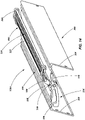
FIG. 10 is a top perspective view of a second rung assembly according to an embodiment of the present invention; -
FIG. 11 is a bottom perspective view of the rung assembly shown inFIG. 10 ; -
FIG. 12 is a side view of the rung assembly shown inFIG. 10 ; -
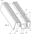
FIG. 13 is a top perspective view of a base member of the rung assembly shown inFIG. 10 ; -
FIG. 14 is a perspective view of a third rung assembly not forming part of the present invention; -
FIG. 15 is a side view of the rung assembly shown inFIG. 14 ; and -
FIG. 16 is a front view of the rung assembly shown inFIG. 14 . - Various ladders, ladder components, assemblies and mechanisms are described herein. The described arrangements are not mutually exclusive of each other. Rather, various features of one described arrangement may be used in conjunction with features of other described arrangements within the scope of the invention as defined by the appended claims.
- Referring initially to
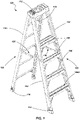
FIG. 1 astepladder 100 is shown in accordance with an embodiment of the present invention. Thestepladder 100 includes afirst assembly 102 having a pair of spaced apartrails 104 and a plurality ofrungs 106 extending between, and coupled to, therails 104. The spaced apartrungs 106 are substantially parallel to one another and are configured to be substantially level when thestepladder 100 is in an orientation for intended use, so that they may be used as "steps" for a user to ascend thestepladder 100 as will be appreciated by those of ordinary skill in the art. In the specific embodiment shown inFIG. 1 , the lowermost rung comprises arung assembly 106A as will be described in further detail below with reference toFIGS. 10-13 . In other embodiments, other rungs (e.g., second lowest rung, top rung, or all rungs) may alternatively, or additionally, comprise a rung assembly if desired. - The
stepladder 100 also includes asecond assembly 108 having a pair of spaced apartrails 110. Thesecond assembly 108 need not include a plurality of rungs between the spacedapart rails 110. Rather, bracing or other structural components may be used to provide a desired level of rigidity and strength to the spaced apartrails 110. However, in some embodiments, thesecond assembly 108 may include rungs configured generally similar to those associated with thefirst assembly 102. Thesecond assembly 108, thus, may be used to help support thestepladder 100 when in an intended operational state, such as generally depicted inFIG. 1 . - The first and
second assemblies rails assemblies 102 and 108 (and their various components) may be formed of other materials including other composites, plastics, polymers, metals, metal alloys or combinations of such materials. - A
top cap 112 is coupled to a portion of thefirst assembly 102 and a portion of the second assembly. For example, thetop cap 112 may be pivotally coupled to an upper end of the eachrail 104 of thefirst assembly 102 along a common axis. In the embodiment shown inFIG. 1 , thetop cap 112 is also pivotally coupled to an upper end of eachrail 110 of thesecond assembly 108 along another common axis. It is noted that the use of the term "upper end" merely refers to a relative position of the described components when thestepladder 100 is in an orientation of intended use orientation. - In one embodiment, the
top cap 112 may simply be a structural component configured to facilitate relative coupling of the first andsecond assemblies top cap 112 may be used to organize a user's tools, supplies and other resources while working on thestepladder 100. For example, such a top cap is described inU.S. Patent No. 8,186, 481 issued May 29, 2012 and entitled LADDERS, LADDER COMPONENTS AND RELATED METHODS. It is noted that, for safety purposes, thetop cap 112 is not conventionally configured as a "rung" or a "step" and may not necessarily be designed to support a user's full weight. As with other components of thestepladder 100, thetop cap 112 may be formed from a variety of materials. In one embodiment, thetop cap 112 may be formed from a plastic material that is molded into a desired size and shape. - The
stepladder 100 may additionally include a plurality of feet 114 (one associated with each rail) configured to engage a supporting surface such as the ground. Thefeet 114 may be configured in a variety of manners based on, for example, the type of environment in which the ladder is anticipated to be used. For example, the feet may be formed of a plastic or polymer material and can be configured with a plurality of ridges, knobs or other features configured to provided increased friction between the ladder and a relatively rigid supporting surface (e.g., concrete, tile or wood). On the other hand, thefeet 114 may be configured with barbs or other sharp protrusions configured to dig into a relatively softer supporting surface (e.g., dirt or grass). - A pair of hinged braces, referred to herein as
spreaders 120, are used to maintain a desired angle between the first andsecond assemblies stepladder 100 is in a deployed or useable state. The hinged nature ofsuch spreaders 120 helps to enable the first andsecond assemblies assemblies spreaders 120 are not configured as rungs or platforms, or otherwise configured to support a user standing thereon. Rather, thespreaders 120 are simply configured to structurally maintain theladder 100 in a deployed position while enabling the rail assemblies to be selectively collapsed relative to each other for storage and transportation of theladder 100. - An example of a ladder having both rail assemblies directly pivotally coupled with the
top cap 112 is set forth inU.S. Patent No. 8,701,831 (Application No.12/716,126 entitled STEPLADDERS AND RELATED METHODS filed March 2, 2010 second assembly 108 may include only a single rail if desired. Other examples of stepladders and top caps are described inU.S. Patent Application No. 14/496,987 entitled STEP LADDERS, COMPONENTS FOR STEP LADDERS AND RELATED METHODS, filed Sept. 25, 2014 U.S. Provisional Application 62/045,979, filed September 4, 2014 - Referring now to
FIGS. 2-5 , afirst rung assembly 106A is shown including abase member 140 that is configured for substantially rigid coupling with therails 104 of thefirst assembly 102 of aladder 100. In the arragement shown, thebase member 140 includes afront wall 142, arear wall 144, and anupper wall 146 extending between and coupled with the front andrear walls various walls upper wall 146 may or may not include traction features (e.g., ridges and grooves) such as are often found in conventional ladder rungs. - A
groove 148 is formed at, and extends along, the front edge of theupper wall 146. Thegroove 148 may be positioned directly between theupper wall 146 and thefront wall 142. In other arrangements, thegroove 148 may be formed wholly in theupper wall 146 or wholly in thefront wall 142. In other arrangements, rather than a singlecontinuous groove 148 that extends substantially the entire width (i.e., extending between therails 104 when attached to a ladder) of thebase member 140, one or more grooves of shorter dimension may extend partially along the width of thebase member 140. In yet other arrangements, thegroove 148 could be located along the rear edge of theupper wall 146, reversing the pivoting action of thedisplaceable member 150 which is described further below. - As just noted, the
assembly 106A further includes adisplaceable member 150 that is coupled with thebase member 140. In the arrangement shown inFIGS. 2-5 , the displaceable member includes an upper wall ortread portion 152, which may include one or more traction features 154 (e.g., ridges and grooves). Thedisplaceable member 150 may include arear wall 156 that is configured to extend to, or beyond, the juncture of therear wall 144 andupper wall 146 of thebase member 140. During actuation of theassembly 106A, therear wall 156 of the displaceable member may help to prevent the inadvertent pinching of a user's body, the catching of clothing or the entrance of foreign objects between thedisplaceable member 150 and thebase 140. - The
displaceable member 150 may also include a pivot member 158 (or multiple pivot members) disposed within thegroove 148 of thebase member 140. Thepivot member 158 may include, for example, an elongated member having a portion thereof that is substantially cylindrical, thepivot member 158 being configured to substantially conform in size and shape with thegroove 148. As seen by comparingFIGS. 4 and5 , thepivot member 158 enables pivoting of thedisplaceable member 150 relative to the fixedbase 140 about an axis extending generally along the front edge of therung assembly 106A (e.g., along or adjacent an edge where thefront wall 142 meets theupper wall 146 of the base 140) and extending between therails 104 of theladder 100. The "unactuated" or "normal" state of the rung assembly is shown inFIG. 4 , with thedisplaceable member 150 positioned so that its tread portion orupper wall 152 is at an acute angle relative to theupper wall 146 of thebase member 140. As shown inFIG. 5 , when actuated (e.g., when a user is standing on the rung assembly), theupper wall 154 of the displaceable member is pivoted such that it is positioned against and substantially parallel with theupper wall 146 of thebase member 140. - The
rung assembly 106A further includes one or morealert mechanisms 170 that, when actuated by displacement of the displaceable member 150 a desired distance (e.g., from the position inFIG. 4 to the position inFIG. 5 ), provides an alert to the user (e.g., by audible noise) informing them that they have stepped on therung assembly 106A. Thus, for example, when therung assembly 106A is placed as the lowermost rung of a ladder (e.g., as shown inFIG. 1 ), thealert mechanism 170 provides a user with information, as they descend, that they have reached the lowermost rung and that their next step downward will be to the ground or other surface supporting theladder 100. - Referring to
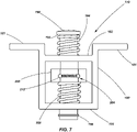
FIGS. 6-9 , thealert mechanism 170 is shown in accordance with an embodiment of the present invention. Thealert mechanism 170 includes a housing member or abracket 180 having flange portions of 181 for coupling with theupper wall 146 of thebase member 140. Thebracket 180 includes twowalls opening pin member 190 extends through theopenings pin member 190 includes ashoulder 192 formed along an upper portion thereof and sized to be wider than theopening 186 formed in theupper wall 182. Theshoulder 192 abuts a biasing member 194 (e.g., a coiled spring or other member) positioned about thepin member 190 between theupper wall 184 and theshoulder 192. Theshoulder 192 cooperates with the biasingmember 194 to retain thepin member 186 within thebracket 180 and also biases thepin 190 upwards relative to thebracket 180. - A
retainer 196 may be coupled to a lower end of the pin member 190 (e.g., a c-clip or snap ring disposed in agroove 198 formed in the pin member) and be configured to abut the lower wall 184 (when displaced towards the lower wall) and retain thepin member 190 within thebracket 180. A sleeve orcollar 200 is slidably positioned about thepin member 190 between the upper andlower walls member 202 is positioned about thepin member 190 and located between thecollar 200 and thelower wall 184 of thebracket 180 and biases the collar upwards toward theupper wall 182. A detent mechanism 204 (FIGS. 7 - 9 ) or other retaining mechanism is associated with thepin member 190 andcollar 200 to retain thecollar 200 at a desired location on thepin member 190 until a force of a specified magnitude is applied against thecollar 200, causing thecollar 200 to slide along thepin member 190 as will be described in further detail below. Thedetent mechanism 204 may include, for example, a biasing member 206 (e.g., a coiled spring) disposed in a throughhole 208 formed in thepin member 190. A pair ofball members 210 may be positioned on each side of the biasingmember 206 so as to partially protrude from the throughhole 208. Agroove 212, which may correspond generally in size to conform with the radius of theball members 210, may be formed on the internal surface of thecollar 200 such that when thegroove 212 is aligned with theball members 210, the ball members are displaced so as to be partially in thegroove 212 and partially in the throughhole 208, holding thecollar 200 in place relative to thepin member 190. Thecollar 200 remains in the held position relative to thepin member 190 until a force is applied to thecollar 200 that is sufficient to overcome the force applied by the biasingmember 206 of the detent mechanism 204 (and any friction forces between theball members 208 and groove of the collar 200), causing theball members 210 to retract within the throughhole 208 and enabling thecollar 200 to slide along the length of thepin member 190. - Thus, in operation, when no force is applied to the alert mechanism (beyond the weight of the displaceable member 150), the
alert mechanism 170 is in the state as shown inFIG. 6 and therung assembly 106A is in the state as shown inFIGS. 2 - 4 . However, when a user steps on therung assembly 106A, their weight causes thepin member 190 to be placed downwards (via the pressure applied to the displaceable member 150) as indicated inFIG. 7 . This causes theupper biasing member 194 to be compressed between theshoulder 192 and theupper wall 182. Additionally, thedetent mechanism 204 holds thecollar 200 in position relative to thepin 190 such that thecollar 200 is displaced along with thepin member 190 and compresses thelower biasing member 202. As thelower biasing member 202 becomes compressed, the force that it exerts against thecollar 200 increases until, when a force of sufficient magnitude is reached, the force of the biasingmember 202 overcomes the holding capacity of thedetent mechanism 204, causing thecollar 200 to be displaced upwards relative to thepin member 190 until it abuts theupper wall 182 as seen inFIG. 8 . This is the "actuated" state of thealert mechanism 170 and therung assembly 106A (as shown inFIG. 5 ). When thecollar 200 is released (i.e., thedetent mechanism 204 releases its hold on the collar 200), thelower biasing member 202 causes thecollar 200 to slap or smack against theupper wall 182 creating a substantial audible event, alerting the user to the fact that they are standing on therung assembly 106A. In certain embodiments, the slap or smack of thecollar 200 against theupper wall 182 may be of sufficient force to also be felt by a user in addition to being heard. - When a user steps off of the
rung assembly 106A, the upper biasing member causes thepin member 190 to be displaced upward, causing thedisplaceable member 150 to be displaced upward (seeFIGS. 2 ,4 and6 ), resetting thedetent mechanism 204 within the groove of thecollar 200, again holding thecollar 200 on thepin member 190 as shown inFIG. 6 . It is noted that twoalert mechanisms 170 are shown inFIG. 3 in association with the described arrangement. However, in other arrangements, asingle alert mechanism 170 may be used or more than two alert mechanisms may be used. - Referring now to
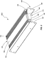
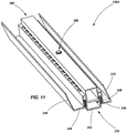
FIGS. 10-13 , asecond rung assembly 106A is shown in accordance with an embodiment of the claimed invention. Therung assembly 106A includes abase member 240 that is configured for substantially rigid coupling with therails 104 of thefirst assembly 102. In the embodiment shown, thebase member 240 includes afront wall 242, arear wall 244, and anupper wall 246 extending between and coupled with the front andrear walls upper wall 246 defines achannel 249 extending across its width. - A
displaceable member 250 is disposed within thechannel 249 and configured to be displaced between at least two positions. Thedisplaceable member 250 includes an upper wall orsurface 252 that may include traction features if desired. Thebase member 240 and thedisplaceable member 250 may include interlocking flange members, 254 and 256, respectively. The interlockingflange members displaceable member 250 within thechannel 249 and define a substantially vertical displacement path for thedisplacement member 250 relative to thebase member 240. - The
rung assembly 106A shown inFIGS. 10-13 may also include one or morealert mechanisms 260 structured similarly to that which has been described above. For example, astructural portion 262 of thebase member 240 may function similar to the housing orbracket 170 described above (e.g., as an integrated bracket or housing). Additionally, thealert mechanism 260 may include apin member 190 extending through openings of thestructural portion 262, biasingmembers collar 200 and a detent mechanism (not shown inFIGS. 10-13 ). Thepin member 190 is in abutting contact with theupper wall 252 of thedisplaceable member 250 so as to be actuated upon displacement of thedisplaceable member 250. - The
alert mechanism 260 functions substantially similar to that described above with respect to the embodiment shown inFIGS. 6-9 . When a user steps on therung assembly 106A, thedisplaceable member 250 is displaced downwards into thechannel 249 until its upper surface is substantially flush or coplanar with theupper surface 246 of thebase member 240. Displacement of thedisplaceable member 250 causes thepin member 190 to also be displaced downward. Thecollar 200 is displaced with thepin member 190 until forces of the associateddetent mechanism 204 are overcome, causing thecollar 200 to be displaced upwards and slap against a surface of thestructural portion 262 of thebase member 240, alerting a user to the fact that they just stepped on therung assembly 106A. - Referring to
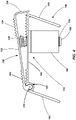
FIGS. 14-16 , athird rung assembly 106A is shown. Theassembly 106A includes abase member 300 that is configured for substantially rigid coupling with therails 104 of thefirst assembly 102. In the arrangement shown, thebase member 300 includes afront wall 302, arear wall 304, and anupper wall 306 extending between and coupled with the front andrear walls upper wall 306 may include traction features 308 (e.g., ridges and grooves) such as are often found in conventional ladder rungs. - A
displaceable member 320 includes anupper surface 322 or a tread member, which may include traction features 324, positioned above theupper wall 306 of thebase member 300. Theupper surface 322 is coupled to twoside arms 326. Theside arms 326 extend throughopenings 328 formed in theupper wall 306 of thebase member 300 and are pivotally coupled to thebase member 300 by way of abracket 330 andpivot member 332. Alower portion 334 of theside arms 326 extends beneath theupper wall 306 of thebase member 300 and includes astriking portion 336. When a user steps on therung assembly 106A shown inFIGS. 14-16 , the weight of the user causes the tread orupper surface 322 of thedisplaceable member 320 to be displaced downward toward theupper wall 306 of thebase member 300. With thetread 322 being displaced downward, theside arms 326 pivot relative to thebase member 300, as indicated by the directional arrow 340 (FIG. 15 ). When theside arms 326 pivot as indicated by direction arrow 340 (FIG. 15 ), thelower portion 334 of theside arms 326 are displaced upwards, as indicated bydirectional arrow 342, causing the striking portion to strike theupper wall 306 of the base member and create a knocking or ringing sound as an alert to the user that they have stepped on therung assembly 106A. Thus, the pivotal side arms function as the alert mechanism in the arrangement shown inFIGS. 14-16 . Thedisplaceable member 320 may return to its unactuated position after a user steps off of the rung assembly due to gravity (e.g., a weight associated with the lower portions of the side arms 326) or by way of a biasing member (not shown) associated with theside arms 326 or thetreat 322. - In any of the arrangements described above, when a user stands on the
rung assembly 106A (which, in the embodiment shown inFIG. 1 is the lowermost rung of the ladder), they will be alerted by an audible alarm, and in some arrangements, by force feedback (e.g., such as feeling a small slap or knock of the rung from the alert mechanism), - as well as by sensing that there is a different "feel" when standing on the rung assembly as compared to other rungs of the ladder - that they are standing on the lowermost "rung" and recognize that they are only one rung or step above the ground. It is noted that the different "feel" when standing on the rung assembly, event after the alert mechanism has been actuated, may take various different forms. For example, the arrangement described with respect toFIGS. 2-5 may include the tread portion residing at a slight angle as compared to other rungs, or it may have a slight rocking feel to it as it rests on the pin members of the alert mechanisms. In the embodiment ofFIGS. 10-13 , the displaceable member may be configured to protrude slightly from the base member when in the second or actuated position giving a slight "uneven" feel across the surface of the rung. Similarly, in the arrangement shown inFIGS. 14-16 , a user will send a slight unevenness in the rung as the displaceable member will rest atop the base member when in the actuated position. - It is noted that the rung assembly may not be located as the lowermost rung of the ladder. For example, it may be located as the second lowermost rung of the ladder, indicating to the user that they still have one more rung to descend prior to reaching the ground.
- One advantage shared by all of the arrangements described herein, is that the front edge of the rung assembly is not substantially displaced in elevation between the unactuated and actuated states. This includes the arrangement shown in
FIGS. 2-5 where the front edge may pivot, but is not substantially displaced in terms of elevation. This provides a positive position of the front edge of the rungs (relative to other components of the ladder, such as the side rails), maintaining the distance between adjacent rungs at their front edges so that the user feels confident as they engage each rung and/or rung assembly. Stated another way, the side front edge of the rung assembly remains at a substantially fixed location on the ladder, even though other components of the rung assembly may be displaced or more relative to, for example, the side rails. - Of course, the specific embodiments described herein are merely examples and a variety of ladder configurations may be used in conjunction with the present invention. While specifically described with respect to use in stepladders, the rung assemblies may be used in other types of ladders, including extension ladders and combination ladders, without limitation. For example, non-limiting examples of extension ladders into which a rung assembly of the present invention may be incorporated are described in
U.S. Patent No. 8,365,865 (U.S. Patent Application No. 12/714,313 filed on Feb. 26, 2010 U.S. Patent No. 7,364,017 (U.S. Patent Application No. 10/706,308, filed on Nov. 11, 2003 - It is further noted that, while various embodiments have been described in terms of generally mechanical assemblies, that other embodiments may also be employed such as an assembly having a sensor associated with a given rung wherein, when actuated, the sensor triggers an audible or sensory (e.g., physical vibration) alarm for a user to perceive. For example, in one embodiment, the combination of a pin/spring/detent mechanism may be replaced by a switch which is coupled with a speaker or a vibrating mechanism to effect an alarm when actuated. Of course other types of sensors and actuators may be employed as well.
- While the invention may be susceptible to various modifications and alternative forms, specific embodiments have been shown by way of example in the drawings and have been described in detail herein. However, it should be understood that the invention is not intended to be limited to the particular forms disclosed. Rather, the scope of the invention as defined by the following appended claims.
Claims (13)
- A ladder (100) comprising:a first assembly (102) comprising a first pair of spaced apart rails (104);a rung assembly (106A) coupled between the first pair of rails (104) comprising:a base member (240) comprising a front wall (242), a rear wall (244), an upper wall (246) extending between the front wall (242) and the rear wall (244), and a channel (249) formed in the upper wall (246) , the channel (249) extending between the first pair of rails (104);a displaceable member (250) coupled with the base member (240), the displaceable member (250) being at least partially disposed within the channel (249) and configured to be displaced from a first position to a second position relative to the base member (240);at least one alert mechanism (260) associated with the displaceable member (250) and configured to provide an audible alert when the displaceable member (250) is displaced from the first position to the second position;wherein a front edge of the rung assembly (106A) extending between the first pair of rails (104) maintains a substantially constant position relative to the first pair of rails (104) when the displaceable member (250) is displaced from the first position to the second position.
- The ladder (100) of claim 1, wherein a portion of the displaceable member (252) protrudes above a surface of the upper wall (246) of the base member (240) when the displaceable member is in the second position.
- The ladder (100) of claim 1, further comprising a plurality of additional rungs (106) extending between and coupled to the first pair of spaced apart rails (104).
- The ladder (100) of claim 3, wherein the rung assembly (106A) is positioned to act as the lowermost rung of the ladder (100).
- The ladder (100) of claim 1, wherein an upper wall (252) of the displaceable member (250) includes an upper tread portion.
- The ladder (100) of claim 5, wherein, when the displaceable member (250) is in the second position, the upper tread portion of the displaceable member (250) is substantially coplanar with the upper wall (246) of the base member (240).
- The ladder (100) of claim 1, wherein the displaceable member (250) includes a first flange member (256), the base member (240) includes a second flange member (254), and wherein the first and second flange members (256, 254) interlock with one another to retain the displaceable member (250) within the channel (249).
- The ladder (100) of claim 7, wherein the displaceable member (246) travels along a substantially vertical displacement path between the first position and the second position.
- The ladder (100) of claim 1, wherein at least a portion of the at least one alert mechanism (260) is disposed within the channel (249).
- The ladder (100) of claim 1, wherein the at least one alert mechanism (260) includes a pin (190), a collar (200) slidably disposed about the pin (190), and a detent mechanism (204) configured to hold the collar (200) at a specified position on the pin (190) until a force of a specified magnitude is applied to the collar (200).
- The (100) ladder of claim 10, wherein the at least one alert mechanism (260) is positioned and configured so that the detent mechanism (204) releases the collar (200) when the displaceable mechanism (250) is in the first position.
- The ladder (100) of claim 11, wherein the at least one alert mechanism (260) includes two alert mechanisms.
- The ladder (100) of claim 1, further comprising:a second assembly (108) comprising at least one rail (110); anda top cap (112) coupled to the first assembly (102) and to the second assembly (108).
Priority Applications (1)
| Application Number | Priority Date | Filing Date | Title |
|---|---|---|---|
| EP22177628.9A EP4083367A1 (en) | 2014-09-12 | 2015-09-10 | Rung assemblies for ladders |
Applications Claiming Priority (3)
| Application Number | Priority Date | Filing Date | Title |
|---|---|---|---|
| US201462049916P | 2014-09-12 | 2014-09-12 | |
| EP15840026.7A EP3191676B1 (en) | 2014-09-12 | 2015-09-10 | Rung assemblies for ladders and ladders |
| PCT/US2015/049446 WO2016040648A1 (en) | 2014-09-12 | 2015-09-10 | Ladders, rung assemblies for ladders and related methods |
Related Parent Applications (1)
| Application Number | Title | Priority Date | Filing Date |
|---|---|---|---|
| EP15840026.7A Division EP3191676B1 (en) | 2014-09-12 | 2015-09-10 | Rung assemblies for ladders and ladders |
Related Child Applications (1)
| Application Number | Title | Priority Date | Filing Date |
|---|---|---|---|
| EP22177628.9A Division EP4083367A1 (en) | 2014-09-12 | 2015-09-10 | Rung assemblies for ladders |
Publications (2)
| Publication Number | Publication Date |
|---|---|
| EP3760827A1 EP3760827A1 (en) | 2021-01-06 |
| EP3760827B1 true EP3760827B1 (en) | 2022-07-06 |
Family
ID=55454245
Family Applications (3)
| Application Number | Title | Priority Date | Filing Date |
|---|---|---|---|
| EP22177628.9A Withdrawn EP4083367A1 (en) | 2014-09-12 | 2015-09-10 | Rung assemblies for ladders |
| EP20189923.4A Active EP3760827B1 (en) | 2014-09-12 | 2015-09-10 | Ladder |
| EP15840026.7A Active EP3191676B1 (en) | 2014-09-12 | 2015-09-10 | Rung assemblies for ladders and ladders |
Family Applications Before (1)
| Application Number | Title | Priority Date | Filing Date |
|---|---|---|---|
| EP22177628.9A Withdrawn EP4083367A1 (en) | 2014-09-12 | 2015-09-10 | Rung assemblies for ladders |
Family Applications After (1)
| Application Number | Title | Priority Date | Filing Date |
|---|---|---|---|
| EP15840026.7A Active EP3191676B1 (en) | 2014-09-12 | 2015-09-10 | Rung assemblies for ladders and ladders |
Country Status (3)
| Country | Link |
|---|---|
| US (2) | US10487578B2 (en) |
| EP (3) | EP4083367A1 (en) |
| WO (1) | WO2016040648A1 (en) |
Families Citing this family (20)
| Publication number | Priority date | Publication date | Assignee | Title |
|---|---|---|---|---|
| US8701831B2 (en) * | 2009-03-03 | 2014-04-22 | Wing Enterprises, Inc. | Stepladders and related methods |
| CN106089015A (en) * | 2016-07-29 | 2016-11-09 | 广东惠利普路桥信息工程有限公司 | A kind of road and bridge construction Multifunction combined ladder |
| CN106351563A (en) * | 2016-08-31 | 2017-01-25 | 张家港市华扬冶金机械有限公司 | Multifunctional folding tool lift |
| US20180252038A1 (en) * | 2017-03-06 | 2018-09-06 | Michael McGarey | Portable step device and method |
| US10538966B2 (en) * | 2017-05-10 | 2020-01-21 | Werner Co. | Ceiling ladder, deep step and method |
| JP6941016B2 (en) * | 2017-09-25 | 2021-09-29 | アルインコ株式会社 | Telescopic lock mechanism of the telescopic leg device in the stepladder that also serves as a ladder |
| US11466516B2 (en) * | 2017-11-10 | 2022-10-11 | Little Giant Ladder Systems, Llc | Walkthrough and standoff mechanisms for ladders, ladders incorporating same and related methods |
| US11499370B2 (en) * | 2018-05-01 | 2022-11-15 | Otto Ladder Safety, Inc. | Ladder having sensor and computing device for same |
| US20190376342A1 (en) | 2018-06-08 | 2019-12-12 | Wing Enterprises, Incorporated | Ladders, feet for ladders and hinges for ladders |
| MX2021001027A (en) * | 2018-07-27 | 2021-11-12 | Little Giant Ladder Systems Llc | Last step indicator for ladders and ladders incorporating same. |
| USD885607S1 (en) | 2018-10-19 | 2020-05-26 | Wing Enterprises, Incorporated | Accessory for ladder |
| USD912847S1 (en) | 2018-10-19 | 2021-03-09 | Little Giant Ladder Systems, Llc | Top cap for ladder |
| USD935054S1 (en) | 2018-10-19 | 2021-11-02 | Little Giant Ladder Systems, Llc | Ladder |
| USD943772S1 (en) | 2018-10-19 | 2022-02-15 | Little Giant Ladder Systems, Llc | Flip-up ladder |
| USD911555S1 (en) | 2019-02-08 | 2021-02-23 | Little Giant Ladder Systems, Llc | Top cap for a ladder |
| USD912848S1 (en) | 2019-02-08 | 2021-03-09 | Little Giant Ladder Systems, Llc | Ladder accessory |
| USD966556S1 (en) | 2019-12-13 | 2022-10-11 | Murphy Ladder Llc | Ladder |
| US10822876B1 (en) | 2020-02-09 | 2020-11-03 | Chad Alan Parks | Systems and methods of use of hanger assemblies for a ladder |
| US20220018190A1 (en) * | 2020-07-17 | 2022-01-20 | Rafael Gonzalez | Smart Safety Ladder |
| US11635307B1 (en) | 2022-04-26 | 2023-04-25 | Stress Engineering Services, Inc. | Hall effect transducer assemblies and methods |
Family Cites Families (33)
| Publication number | Priority date | Publication date | Assignee | Title |
|---|---|---|---|---|
| US8186A (en) | 1851-07-01 | Arrangement oe catches in the upper sash operated by moving the | ||
| US481A (en) | 1837-11-23 | Improvement in the pistol-saber | ||
| US1141716A (en) * | 1914-05-18 | 1915-06-01 | Charles Rickard Kjellstrom | Combined fire-escape and alarm. |
| US3233702A (en) * | 1964-05-08 | 1966-02-08 | Floyd L Feltrop | Self-leveling ladder |
| US3298012A (en) * | 1964-09-23 | 1967-01-10 | Weller Newton | Ladder warning device |
| US4403373A (en) * | 1980-02-15 | 1983-09-13 | Kuemmerlin Walter | Hinge fitting for foldable ladders |
| US4407045A (en) * | 1981-12-21 | 1983-10-04 | Boothe Leland H | Ladder hinge and multi-position locking mechanism therefor |
| US4566150A (en) * | 1981-12-21 | 1986-01-28 | Little Giant Industries, Inc. | Ladder hinge and multi-position locking mechanism therefor |
| US5954154A (en) * | 1998-05-14 | 1999-09-21 | Ziolkowski; Robert L. | Ladder with bottom step indicator |
| US5971102A (en) * | 1998-08-17 | 1999-10-26 | Brown; Norma | Ladder including storage compartments |
| US6405829B1 (en) * | 2000-01-28 | 2002-06-18 | Triodyne Safety Systems, L.L.C. | Anti-slide out devices for straight and extension ladders |
| US6578663B2 (en) | 2001-09-24 | 2003-06-17 | Green Bull, Inc. | Step signal |
| NZ540647A (en) | 2002-11-11 | 2008-10-31 | Wing Entpr | Combination ladders, ladder components and methods of manufacturing same |
| US6966403B1 (en) * | 2003-02-10 | 2005-11-22 | Suresh Chandra | Smart ladder |
| US20060032704A1 (en) * | 2003-02-11 | 2006-02-16 | Suresh Chandra | Smart ladder |
| US20050173189A1 (en) * | 2004-02-10 | 2005-08-11 | Philip Berardi | Ladder hazard alert |
| US7174994B1 (en) * | 2004-02-19 | 2007-02-13 | Coffield Tamara L | Utility ladder |
| US20090139798A1 (en) * | 2007-12-03 | 2009-06-04 | Bernard David J | Position indicating steps |
| CA3160141A1 (en) * | 2008-03-07 | 2009-09-11 | Little Giant Ladder Systems, Llc | Ladders, ladder components and related methods |
| US8701831B2 (en) | 2009-03-03 | 2014-04-22 | Wing Enterprises, Inc. | Stepladders and related methods |
| US8365865B2 (en) | 2009-03-03 | 2013-02-05 | Wing Enterprises, Inc. | Adjustable ladders and related methods |
| US8167087B2 (en) * | 2009-03-09 | 2012-05-01 | The United States Of America As Represented By The Secretary Of The Department Of Health And Human Services, Centers For Disease Control And Prevention | Multimodal indicator safety device for ladder positioning |
| US20130140111A1 (en) * | 2011-12-01 | 2013-06-06 | Kishor Chandra Desai | Safety ladder warning device |
| US20140231170A1 (en) * | 2013-02-14 | 2014-08-21 | William Frame | Step sensor and ladder having same |
| US20160273746A9 (en) * | 2013-04-03 | 2016-09-22 | Adaptive Rescue Concepts, LLC | Lighting Assembly for a Ladder |
| WO2015048271A1 (en) * | 2013-09-27 | 2015-04-02 | Wing Enterprises, Incorporated | Step ladders, components for step ladders and related methods |
| CN203531733U (en) * | 2013-10-25 | 2014-04-09 | 国家电网公司 | Warning safety ladder |
| US20160356086A1 (en) * | 2015-06-08 | 2016-12-08 | Asia Connection LLC | Electronic component for a step ladder |
| US9711028B1 (en) * | 2015-07-07 | 2017-07-18 | Benjamin Friedman | Electrical warning system for a step ladder |
| US10094170B2 (en) * | 2015-07-07 | 2018-10-09 | Benjamin Friedman | Electrical warning system for a climbable structure |
| US10351055B2 (en) * | 2017-06-12 | 2019-07-16 | Mac LTT, Inc. | Deployable alarming and safety zone for use with a tanker delivery |
| US10260282B1 (en) * | 2018-07-25 | 2019-04-16 | David Bautista | Electronic safety structure and system |
| US10706308B2 (en) | 2018-08-07 | 2020-07-07 | Accenture Global Solutions Limited | Image processing for automated object identification |
-
2015
- 2015-09-10 WO PCT/US2015/049446 patent/WO2016040648A1/en active Application Filing
- 2015-09-10 EP EP22177628.9A patent/EP4083367A1/en not_active Withdrawn
- 2015-09-10 EP EP20189923.4A patent/EP3760827B1/en active Active
- 2015-09-10 US US14/849,917 patent/US10487578B2/en active Active
- 2015-09-10 EP EP15840026.7A patent/EP3191676B1/en active Active
-
2019
- 2019-11-22 US US16/693,013 patent/US20200165868A1/en active Pending
Also Published As
| Publication number | Publication date |
|---|---|
| EP3191676A1 (en) | 2017-07-19 |
| EP3191676B1 (en) | 2020-08-12 |
| EP3760827A1 (en) | 2021-01-06 |
| EP4083367A1 (en) | 2022-11-02 |
| US20200165868A1 (en) | 2020-05-28 |
| US20160076304A1 (en) | 2016-03-17 |
| US10487578B2 (en) | 2019-11-26 |
| WO2016040648A1 (en) | 2016-03-17 |
| EP3191676A4 (en) | 2018-05-30 |
Similar Documents
| Publication | Publication Date | Title |
|---|---|---|
| EP3760827B1 (en) | Ladder | |
| US20240035337A1 (en) | Last step indicator for ladders and ladders incorporating same | |
| US10597941B2 (en) | Step ladders, components for step ladders and related methods | |
| US11746596B2 (en) | Adjustable ladders, ladder components and related methods | |
| US10590702B2 (en) | Ladders, mechanisms and components for ladders, and related methods | |
| EP3411556B1 (en) | Elevated working platform and related methods | |
| RU2531710C2 (en) | Adjustable ladder | |
| US11441356B2 (en) | Ladders, top cap for ladders and trays for ladders | |
| EP2870314B1 (en) | Collapsible ladder | |
| US10900282B2 (en) | Safety ladder | |
| US11578533B2 (en) | Step ladder device allowing the user to stand and work safely and comfortably on the upper steps of a step ladder | |
| CA2936214A1 (en) | Ladder safety device | |
| US20140047782A1 (en) | Ground anchor for outdoor implements | |
| US20210222492A1 (en) | Ladders and ladder rungs | |
| WO2008041156A2 (en) | A-framed step ladder with slidably displaceable extension member | |
| US20220397000A1 (en) | Safety Ladder Device |
Legal Events
| Date | Code | Title | Description |
|---|---|---|---|
| PUAI | Public reference made under article 153(3) epc to a published international application that has entered the european phase |
Free format text: ORIGINAL CODE: 0009012 |
|
| STAA | Information on the status of an ep patent application or granted ep patent |
Free format text: STATUS: THE APPLICATION HAS BEEN PUBLISHED |
|
| AC | Divisional application: reference to earlier application |
Ref document number: 3191676 Country of ref document: EP Kind code of ref document: P |
|
| AK | Designated contracting states |
Kind code of ref document: A1 Designated state(s): AL AT BE BG CH CY CZ DE DK EE ES FI FR GB GR HR HU IE IS IT LI LT LU LV MC MK MT NL NO PL PT RO RS SE SI SK SM TR |
|
| RAP3 | Party data changed (applicant data changed or rights of an application transferred) |
Owner name: LITTLE GIANT LADDER SYSTEMS, LLC |
|
| STAA | Information on the status of an ep patent application or granted ep patent |
Free format text: STATUS: REQUEST FOR EXAMINATION WAS MADE |
|
| RAP3 | Party data changed (applicant data changed or rights of an application transferred) |
Owner name: LITTLE GIANT LADDER SYSTEMS, LLC |
|
| 17P | Request for examination filed |
Effective date: 20210702 |
|
| RBV | Designated contracting states (corrected) |
Designated state(s): AL AT BE BG CH CY CZ DE DK EE ES FI FR GB GR HR HU IE IS IT LI LT LU LV MC MK MT NL NO PL PT RO RS SE SI SK SM TR |
|
| RIC1 | Information provided on ipc code assigned before grant |
Ipc: E06C 7/08 20060101ALI20211203BHEP Ipc: E06C 7/00 20060101AFI20211203BHEP |
|
| GRAJ | Information related to disapproval of communication of intention to grant by the applicant or resumption of examination proceedings by the epo deleted |
Free format text: ORIGINAL CODE: EPIDOSDIGR1 |
|
| STAA | Information on the status of an ep patent application or granted ep patent |
Free format text: STATUS: GRANT OF PATENT IS INTENDED |
|
| GRAP | Despatch of communication of intention to grant a patent |
Free format text: ORIGINAL CODE: EPIDOSNIGR1 |
|
| INTG | Intention to grant announced |
Effective date: 20220125 |
|
| GRAS | Grant fee paid |
Free format text: ORIGINAL CODE: EPIDOSNIGR3 |
|
| GRAA | (expected) grant |
Free format text: ORIGINAL CODE: 0009210 |
|
| STAA | Information on the status of an ep patent application or granted ep patent |
Free format text: STATUS: THE PATENT HAS BEEN GRANTED |
|
| AC | Divisional application: reference to earlier application |
Ref document number: 3191676 Country of ref document: EP Kind code of ref document: P |
|
| AK | Designated contracting states |
Kind code of ref document: B1 Designated state(s): AL AT BE BG CH CY CZ DE DK EE ES FI FR GB GR HR HU IE IS IT LI LT LU LV MC MK MT NL NO PL PT RO RS SE SI SK SM TR |
|
| REG | Reference to a national code |
Ref country code: AT Ref legal event code: REF Ref document number: 1503009 Country of ref document: AT Kind code of ref document: T Effective date: 20220715 Ref country code: CH Ref legal event code: EP |
|
| RIN2 | Information on inventor provided after grant (corrected) |
Inventor name: JONAS, GARY Inventor name: WRIGHT, BRYAN Inventor name: MOSS, RYAN N. Inventor name: RUSSELL, BRIAN Inventor name: PETERSON, SEAN Inventor name: COOK, BENJAMIN Inventor name: SMITH, CHRISTIAN |
|
| REG | Reference to a national code |
Ref country code: DE Ref legal event code: R096 Ref document number: 602015079829 Country of ref document: DE |
|
| REG | Reference to a national code |
Ref country code: IE Ref legal event code: FG4D |
|
| REG | Reference to a national code |
Ref country code: LT Ref legal event code: MG9D |
|
| REG | Reference to a national code |
Ref country code: NL Ref legal event code: MP Effective date: 20220706 |
|
| PG25 | Lapsed in a contracting state [announced via postgrant information from national office to epo] |
Ref country code: SE Free format text: LAPSE BECAUSE OF FAILURE TO SUBMIT A TRANSLATION OF THE DESCRIPTION OR TO PAY THE FEE WITHIN THE PRESCRIBED TIME-LIMIT Effective date: 20220706 Ref country code: RS Free format text: LAPSE BECAUSE OF FAILURE TO SUBMIT A TRANSLATION OF THE DESCRIPTION OR TO PAY THE FEE WITHIN THE PRESCRIBED TIME-LIMIT Effective date: 20220706 Ref country code: PT Free format text: LAPSE BECAUSE OF FAILURE TO SUBMIT A TRANSLATION OF THE DESCRIPTION OR TO PAY THE FEE WITHIN THE PRESCRIBED TIME-LIMIT Effective date: 20221107 Ref country code: NO Free format text: LAPSE BECAUSE OF FAILURE TO SUBMIT A TRANSLATION OF THE DESCRIPTION OR TO PAY THE FEE WITHIN THE PRESCRIBED TIME-LIMIT Effective date: 20221006 Ref country code: NL Free format text: LAPSE BECAUSE OF FAILURE TO SUBMIT A TRANSLATION OF THE DESCRIPTION OR TO PAY THE FEE WITHIN THE PRESCRIBED TIME-LIMIT Effective date: 20220706 Ref country code: LV Free format text: LAPSE BECAUSE OF FAILURE TO SUBMIT A TRANSLATION OF THE DESCRIPTION OR TO PAY THE FEE WITHIN THE PRESCRIBED TIME-LIMIT Effective date: 20220706 Ref country code: LT Free format text: LAPSE BECAUSE OF FAILURE TO SUBMIT A TRANSLATION OF THE DESCRIPTION OR TO PAY THE FEE WITHIN THE PRESCRIBED TIME-LIMIT Effective date: 20220706 Ref country code: FI Free format text: LAPSE BECAUSE OF FAILURE TO SUBMIT A TRANSLATION OF THE DESCRIPTION OR TO PAY THE FEE WITHIN THE PRESCRIBED TIME-LIMIT Effective date: 20220706 Ref country code: ES Free format text: LAPSE BECAUSE OF FAILURE TO SUBMIT A TRANSLATION OF THE DESCRIPTION OR TO PAY THE FEE WITHIN THE PRESCRIBED TIME-LIMIT Effective date: 20220706 |
|
| PGFP | Annual fee paid to national office [announced via postgrant information from national office to epo] |
Ref country code: DE Payment date: 20221007 Year of fee payment: 8 |
|
| REG | Reference to a national code |
Ref country code: AT Ref legal event code: MK05 Ref document number: 1503009 Country of ref document: AT Kind code of ref document: T Effective date: 20220706 |
|
| PG25 | Lapsed in a contracting state [announced via postgrant information from national office to epo] |
Ref country code: PL Free format text: LAPSE BECAUSE OF FAILURE TO SUBMIT A TRANSLATION OF THE DESCRIPTION OR TO PAY THE FEE WITHIN THE PRESCRIBED TIME-LIMIT Effective date: 20220706 Ref country code: IS Free format text: LAPSE BECAUSE OF FAILURE TO SUBMIT A TRANSLATION OF THE DESCRIPTION OR TO PAY THE FEE WITHIN THE PRESCRIBED TIME-LIMIT Effective date: 20221106 Ref country code: HR Free format text: LAPSE BECAUSE OF FAILURE TO SUBMIT A TRANSLATION OF THE DESCRIPTION OR TO PAY THE FEE WITHIN THE PRESCRIBED TIME-LIMIT Effective date: 20220706 Ref country code: GR Free format text: LAPSE BECAUSE OF FAILURE TO SUBMIT A TRANSLATION OF THE DESCRIPTION OR TO PAY THE FEE WITHIN THE PRESCRIBED TIME-LIMIT Effective date: 20221007 |
|
| REG | Reference to a national code |
Ref country code: DE Ref legal event code: R097 Ref document number: 602015079829 Country of ref document: DE |
|
| PG25 | Lapsed in a contracting state [announced via postgrant information from national office to epo] |
Ref country code: SM Free format text: LAPSE BECAUSE OF FAILURE TO SUBMIT A TRANSLATION OF THE DESCRIPTION OR TO PAY THE FEE WITHIN THE PRESCRIBED TIME-LIMIT Effective date: 20220706 Ref country code: RO Free format text: LAPSE BECAUSE OF FAILURE TO SUBMIT A TRANSLATION OF THE DESCRIPTION OR TO PAY THE FEE WITHIN THE PRESCRIBED TIME-LIMIT Effective date: 20220706 Ref country code: MC Free format text: LAPSE BECAUSE OF FAILURE TO SUBMIT A TRANSLATION OF THE DESCRIPTION OR TO PAY THE FEE WITHIN THE PRESCRIBED TIME-LIMIT Effective date: 20220706 Ref country code: DK Free format text: LAPSE BECAUSE OF FAILURE TO SUBMIT A TRANSLATION OF THE DESCRIPTION OR TO PAY THE FEE WITHIN THE PRESCRIBED TIME-LIMIT Effective date: 20220706 Ref country code: CZ Free format text: LAPSE BECAUSE OF FAILURE TO SUBMIT A TRANSLATION OF THE DESCRIPTION OR TO PAY THE FEE WITHIN THE PRESCRIBED TIME-LIMIT Effective date: 20220706 Ref country code: AT Free format text: LAPSE BECAUSE OF FAILURE TO SUBMIT A TRANSLATION OF THE DESCRIPTION OR TO PAY THE FEE WITHIN THE PRESCRIBED TIME-LIMIT Effective date: 20220706 |
|
| REG | Reference to a national code |
Ref country code: CH Ref legal event code: PL |
|
| PLBE | No opposition filed within time limit |
Free format text: ORIGINAL CODE: 0009261 |
|
| STAA | Information on the status of an ep patent application or granted ep patent |
Free format text: STATUS: NO OPPOSITION FILED WITHIN TIME LIMIT |
|
| REG | Reference to a national code |
Ref country code: BE Ref legal event code: MM Effective date: 20220930 |
|
| PG25 | Lapsed in a contracting state [announced via postgrant information from national office to epo] |
Ref country code: SK Free format text: LAPSE BECAUSE OF FAILURE TO SUBMIT A TRANSLATION OF THE DESCRIPTION OR TO PAY THE FEE WITHIN THE PRESCRIBED TIME-LIMIT Effective date: 20220706 Ref country code: EE Free format text: LAPSE BECAUSE OF FAILURE TO SUBMIT A TRANSLATION OF THE DESCRIPTION OR TO PAY THE FEE WITHIN THE PRESCRIBED TIME-LIMIT Effective date: 20220706 |
|
| 26N | No opposition filed |
Effective date: 20230411 |
|
| P01 | Opt-out of the competence of the unified patent court (upc) registered |
Effective date: 20230518 |
|
| PG25 | Lapsed in a contracting state [announced via postgrant information from national office to epo] |
Ref country code: LU Free format text: LAPSE BECAUSE OF NON-PAYMENT OF DUE FEES Effective date: 20220910 Ref country code: AL Free format text: LAPSE BECAUSE OF FAILURE TO SUBMIT A TRANSLATION OF THE DESCRIPTION OR TO PAY THE FEE WITHIN THE PRESCRIBED TIME-LIMIT Effective date: 20220706 |
|
| PG25 | Lapsed in a contracting state [announced via postgrant information from national office to epo] |
Ref country code: LI Free format text: LAPSE BECAUSE OF NON-PAYMENT OF DUE FEES Effective date: 20220930 Ref country code: IE Free format text: LAPSE BECAUSE OF NON-PAYMENT OF DUE FEES Effective date: 20220910 Ref country code: CH Free format text: LAPSE BECAUSE OF NON-PAYMENT OF DUE FEES Effective date: 20220930 |
|
| PG25 | Lapsed in a contracting state [announced via postgrant information from national office to epo] |
Ref country code: SI Free format text: LAPSE BECAUSE OF FAILURE TO SUBMIT A TRANSLATION OF THE DESCRIPTION OR TO PAY THE FEE WITHIN THE PRESCRIBED TIME-LIMIT Effective date: 20220706 |
|
| PG25 | Lapsed in a contracting state [announced via postgrant information from national office to epo] |
Ref country code: BE Free format text: LAPSE BECAUSE OF NON-PAYMENT OF DUE FEES Effective date: 20220930 |
|
| PGFP | Annual fee paid to national office [announced via postgrant information from national office to epo] |
Ref country code: GB Payment date: 20230720 Year of fee payment: 9 |
|
| PGFP | Annual fee paid to national office [announced via postgrant information from national office to epo] |
Ref country code: FR Payment date: 20230703 Year of fee payment: 9 |
|
| PG25 | Lapsed in a contracting state [announced via postgrant information from national office to epo] |
Ref country code: IT Free format text: LAPSE BECAUSE OF FAILURE TO SUBMIT A TRANSLATION OF THE DESCRIPTION OR TO PAY THE FEE WITHIN THE PRESCRIBED TIME-LIMIT Effective date: 20220706 |