EP3760474B1 - Charging method, apparatus and device, medium, battery management system and charging pile - Google Patents
Charging method, apparatus and device, medium, battery management system and charging pile Download PDFInfo
- Publication number
- EP3760474B1 EP3760474B1 EP19891484.8A EP19891484A EP3760474B1 EP 3760474 B1 EP3760474 B1 EP 3760474B1 EP 19891484 A EP19891484 A EP 19891484A EP 3760474 B1 EP3760474 B1 EP 3760474B1
- Authority
- EP
- European Patent Office
- Prior art keywords
- charging
- battery
- target
- parameters
- parameter
- Prior art date
- Legal status (The legal status is an assumption and is not a legal conclusion. Google has not performed a legal analysis and makes no representation as to the accuracy of the status listed.)
- Active
Links
Images


Classifications
-
- B—PERFORMING OPERATIONS; TRANSPORTING
- B60—VEHICLES IN GENERAL
- B60L—PROPULSION OF ELECTRICALLY-PROPELLED VEHICLES; SUPPLYING ELECTRIC POWER FOR AUXILIARY EQUIPMENT OF ELECTRICALLY-PROPELLED VEHICLES; ELECTRODYNAMIC BRAKE SYSTEMS FOR VEHICLES IN GENERAL; MAGNETIC SUSPENSION OR LEVITATION FOR VEHICLES; MONITORING OPERATING VARIABLES OF ELECTRICALLY-PROPELLED VEHICLES; ELECTRIC SAFETY DEVICES FOR ELECTRICALLY-PROPELLED VEHICLES
- B60L53/00—Methods of charging batteries, specially adapted for electric vehicles; Charging stations or on-board charging equipment therefor; Exchange of energy storage elements in electric vehicles
- B60L53/30—Constructional details of charging stations
- B60L53/305—Communication interfaces
-
- B—PERFORMING OPERATIONS; TRANSPORTING
- B60—VEHICLES IN GENERAL
- B60L—PROPULSION OF ELECTRICALLY-PROPELLED VEHICLES; SUPPLYING ELECTRIC POWER FOR AUXILIARY EQUIPMENT OF ELECTRICALLY-PROPELLED VEHICLES; ELECTRODYNAMIC BRAKE SYSTEMS FOR VEHICLES IN GENERAL; MAGNETIC SUSPENSION OR LEVITATION FOR VEHICLES; MONITORING OPERATING VARIABLES OF ELECTRICALLY-PROPELLED VEHICLES; ELECTRIC SAFETY DEVICES FOR ELECTRICALLY-PROPELLED VEHICLES
- B60L53/00—Methods of charging batteries, specially adapted for electric vehicles; Charging stations or on-board charging equipment therefor; Exchange of energy storage elements in electric vehicles
- B60L53/30—Constructional details of charging stations
- B60L53/31—Charging columns specially adapted for electric vehicles
-
- B—PERFORMING OPERATIONS; TRANSPORTING
- B60—VEHICLES IN GENERAL
- B60L—PROPULSION OF ELECTRICALLY-PROPELLED VEHICLES; SUPPLYING ELECTRIC POWER FOR AUXILIARY EQUIPMENT OF ELECTRICALLY-PROPELLED VEHICLES; ELECTRODYNAMIC BRAKE SYSTEMS FOR VEHICLES IN GENERAL; MAGNETIC SUSPENSION OR LEVITATION FOR VEHICLES; MONITORING OPERATING VARIABLES OF ELECTRICALLY-PROPELLED VEHICLES; ELECTRIC SAFETY DEVICES FOR ELECTRICALLY-PROPELLED VEHICLES
- B60L53/00—Methods of charging batteries, specially adapted for electric vehicles; Charging stations or on-board charging equipment therefor; Exchange of energy storage elements in electric vehicles
- B60L53/60—Monitoring or controlling charging stations
- B60L53/62—Monitoring or controlling charging stations in response to charging parameters, e.g. current, voltage or electrical charge
-
- B—PERFORMING OPERATIONS; TRANSPORTING
- B60—VEHICLES IN GENERAL
- B60L—PROPULSION OF ELECTRICALLY-PROPELLED VEHICLES; SUPPLYING ELECTRIC POWER FOR AUXILIARY EQUIPMENT OF ELECTRICALLY-PROPELLED VEHICLES; ELECTRODYNAMIC BRAKE SYSTEMS FOR VEHICLES IN GENERAL; MAGNETIC SUSPENSION OR LEVITATION FOR VEHICLES; MONITORING OPERATING VARIABLES OF ELECTRICALLY-PROPELLED VEHICLES; ELECTRIC SAFETY DEVICES FOR ELECTRICALLY-PROPELLED VEHICLES
- B60L53/00—Methods of charging batteries, specially adapted for electric vehicles; Charging stations or on-board charging equipment therefor; Exchange of energy storage elements in electric vehicles
- B60L53/60—Monitoring or controlling charging stations
- B60L53/63—Monitoring or controlling charging stations in response to network capacity
-
- B—PERFORMING OPERATIONS; TRANSPORTING
- B60—VEHICLES IN GENERAL
- B60L—PROPULSION OF ELECTRICALLY-PROPELLED VEHICLES; SUPPLYING ELECTRIC POWER FOR AUXILIARY EQUIPMENT OF ELECTRICALLY-PROPELLED VEHICLES; ELECTRODYNAMIC BRAKE SYSTEMS FOR VEHICLES IN GENERAL; MAGNETIC SUSPENSION OR LEVITATION FOR VEHICLES; MONITORING OPERATING VARIABLES OF ELECTRICALLY-PROPELLED VEHICLES; ELECTRIC SAFETY DEVICES FOR ELECTRICALLY-PROPELLED VEHICLES
- B60L53/00—Methods of charging batteries, specially adapted for electric vehicles; Charging stations or on-board charging equipment therefor; Exchange of energy storage elements in electric vehicles
- B60L53/60—Monitoring or controlling charging stations
- B60L53/64—Optimising energy costs, e.g. responding to electricity rates
-
- B—PERFORMING OPERATIONS; TRANSPORTING
- B60—VEHICLES IN GENERAL
- B60L—PROPULSION OF ELECTRICALLY-PROPELLED VEHICLES; SUPPLYING ELECTRIC POWER FOR AUXILIARY EQUIPMENT OF ELECTRICALLY-PROPELLED VEHICLES; ELECTRODYNAMIC BRAKE SYSTEMS FOR VEHICLES IN GENERAL; MAGNETIC SUSPENSION OR LEVITATION FOR VEHICLES; MONITORING OPERATING VARIABLES OF ELECTRICALLY-PROPELLED VEHICLES; ELECTRIC SAFETY DEVICES FOR ELECTRICALLY-PROPELLED VEHICLES
- B60L53/00—Methods of charging batteries, specially adapted for electric vehicles; Charging stations or on-board charging equipment therefor; Exchange of energy storage elements in electric vehicles
- B60L53/60—Monitoring or controlling charging stations
- B60L53/66—Data transfer between charging stations and vehicles
-
- B—PERFORMING OPERATIONS; TRANSPORTING
- B60—VEHICLES IN GENERAL
- B60L—PROPULSION OF ELECTRICALLY-PROPELLED VEHICLES; SUPPLYING ELECTRIC POWER FOR AUXILIARY EQUIPMENT OF ELECTRICALLY-PROPELLED VEHICLES; ELECTRODYNAMIC BRAKE SYSTEMS FOR VEHICLES IN GENERAL; MAGNETIC SUSPENSION OR LEVITATION FOR VEHICLES; MONITORING OPERATING VARIABLES OF ELECTRICALLY-PROPELLED VEHICLES; ELECTRIC SAFETY DEVICES FOR ELECTRICALLY-PROPELLED VEHICLES
- B60L53/00—Methods of charging batteries, specially adapted for electric vehicles; Charging stations or on-board charging equipment therefor; Exchange of energy storage elements in electric vehicles
- B60L53/60—Monitoring or controlling charging stations
- B60L53/66—Data transfer between charging stations and vehicles
- B60L53/665—Methods related to measuring, billing or payment
-
- B—PERFORMING OPERATIONS; TRANSPORTING
- B60—VEHICLES IN GENERAL
- B60L—PROPULSION OF ELECTRICALLY-PROPELLED VEHICLES; SUPPLYING ELECTRIC POWER FOR AUXILIARY EQUIPMENT OF ELECTRICALLY-PROPELLED VEHICLES; ELECTRODYNAMIC BRAKE SYSTEMS FOR VEHICLES IN GENERAL; MAGNETIC SUSPENSION OR LEVITATION FOR VEHICLES; MONITORING OPERATING VARIABLES OF ELECTRICALLY-PROPELLED VEHICLES; ELECTRIC SAFETY DEVICES FOR ELECTRICALLY-PROPELLED VEHICLES
- B60L58/00—Methods or circuit arrangements for monitoring or controlling batteries or fuel cells, specially adapted for electric vehicles
- B60L58/10—Methods or circuit arrangements for monitoring or controlling batteries or fuel cells, specially adapted for electric vehicles for monitoring or controlling batteries
-
- B—PERFORMING OPERATIONS; TRANSPORTING
- B60—VEHICLES IN GENERAL
- B60L—PROPULSION OF ELECTRICALLY-PROPELLED VEHICLES; SUPPLYING ELECTRIC POWER FOR AUXILIARY EQUIPMENT OF ELECTRICALLY-PROPELLED VEHICLES; ELECTRODYNAMIC BRAKE SYSTEMS FOR VEHICLES IN GENERAL; MAGNETIC SUSPENSION OR LEVITATION FOR VEHICLES; MONITORING OPERATING VARIABLES OF ELECTRICALLY-PROPELLED VEHICLES; ELECTRIC SAFETY DEVICES FOR ELECTRICALLY-PROPELLED VEHICLES
- B60L58/00—Methods or circuit arrangements for monitoring or controlling batteries or fuel cells, specially adapted for electric vehicles
- B60L58/10—Methods or circuit arrangements for monitoring or controlling batteries or fuel cells, specially adapted for electric vehicles for monitoring or controlling batteries
- B60L58/12—Methods or circuit arrangements for monitoring or controlling batteries or fuel cells, specially adapted for electric vehicles for monitoring or controlling batteries responding to state of charge [SoC]
-
- B—PERFORMING OPERATIONS; TRANSPORTING
- B60—VEHICLES IN GENERAL
- B60L—PROPULSION OF ELECTRICALLY-PROPELLED VEHICLES; SUPPLYING ELECTRIC POWER FOR AUXILIARY EQUIPMENT OF ELECTRICALLY-PROPELLED VEHICLES; ELECTRODYNAMIC BRAKE SYSTEMS FOR VEHICLES IN GENERAL; MAGNETIC SUSPENSION OR LEVITATION FOR VEHICLES; MONITORING OPERATING VARIABLES OF ELECTRICALLY-PROPELLED VEHICLES; ELECTRIC SAFETY DEVICES FOR ELECTRICALLY-PROPELLED VEHICLES
- B60L58/00—Methods or circuit arrangements for monitoring or controlling batteries or fuel cells, specially adapted for electric vehicles
- B60L58/10—Methods or circuit arrangements for monitoring or controlling batteries or fuel cells, specially adapted for electric vehicles for monitoring or controlling batteries
- B60L58/12—Methods or circuit arrangements for monitoring or controlling batteries or fuel cells, specially adapted for electric vehicles for monitoring or controlling batteries responding to state of charge [SoC]
- B60L58/13—Maintaining the SoC within a determined range
-
- B—PERFORMING OPERATIONS; TRANSPORTING
- B60—VEHICLES IN GENERAL
- B60L—PROPULSION OF ELECTRICALLY-PROPELLED VEHICLES; SUPPLYING ELECTRIC POWER FOR AUXILIARY EQUIPMENT OF ELECTRICALLY-PROPELLED VEHICLES; ELECTRODYNAMIC BRAKE SYSTEMS FOR VEHICLES IN GENERAL; MAGNETIC SUSPENSION OR LEVITATION FOR VEHICLES; MONITORING OPERATING VARIABLES OF ELECTRICALLY-PROPELLED VEHICLES; ELECTRIC SAFETY DEVICES FOR ELECTRICALLY-PROPELLED VEHICLES
- B60L58/00—Methods or circuit arrangements for monitoring or controlling batteries or fuel cells, specially adapted for electric vehicles
- B60L58/10—Methods or circuit arrangements for monitoring or controlling batteries or fuel cells, specially adapted for electric vehicles for monitoring or controlling batteries
- B60L58/16—Methods or circuit arrangements for monitoring or controlling batteries or fuel cells, specially adapted for electric vehicles for monitoring or controlling batteries responding to battery ageing, e.g. to the number of charging cycles or the state of health [SoH]
-
- H—ELECTRICITY
- H02—GENERATION; CONVERSION OR DISTRIBUTION OF ELECTRIC POWER
- H02J—ELECTRIC POWER NETWORKS; CIRCUIT ARRANGEMENTS OR SYSTEMS FOR SUPPLYING OR DISTRIBUTING ELECTRIC POWER; SYSTEMS FOR STORING ELECTRIC ENERGY
- H02J7/00—Circuit arrangements for charging or discharging batteries or for supplying loads from batteries
- H02J7/40—Circuit arrangements for charging or discharging batteries or for supplying loads from batteries characterised by the exchange of charge or discharge related data
-
- H—ELECTRICITY
- H02—GENERATION; CONVERSION OR DISTRIBUTION OF ELECTRIC POWER
- H02J—ELECTRIC POWER NETWORKS; CIRCUIT ARRANGEMENTS OR SYSTEMS FOR SUPPLYING OR DISTRIBUTING ELECTRIC POWER; SYSTEMS FOR STORING ELECTRIC ENERGY
- H02J7/00—Circuit arrangements for charging or discharging batteries or for supplying loads from batteries
- H02J7/80—Circuit arrangements for charging or discharging batteries or for supplying loads from batteries including monitoring or indicating arrangements
- H02J7/82—Control of state of charge [SOC]
-
- H—ELECTRICITY
- H02—GENERATION; CONVERSION OR DISTRIBUTION OF ELECTRIC POWER
- H02J—ELECTRIC POWER NETWORKS; CIRCUIT ARRANGEMENTS OR SYSTEMS FOR SUPPLYING OR DISTRIBUTING ELECTRIC POWER; SYSTEMS FOR STORING ELECTRIC ENERGY
- H02J7/00—Circuit arrangements for charging or discharging batteries or for supplying loads from batteries
- H02J7/80—Circuit arrangements for charging or discharging batteries or for supplying loads from batteries including monitoring or indicating arrangements
- H02J7/84—Control of state of health [SOH]
-
- H—ELECTRICITY
- H02—GENERATION; CONVERSION OR DISTRIBUTION OF ELECTRIC POWER
- H02J—ELECTRIC POWER NETWORKS; CIRCUIT ARRANGEMENTS OR SYSTEMS FOR SUPPLYING OR DISTRIBUTING ELECTRIC POWER; SYSTEMS FOR STORING ELECTRIC ENERGY
- H02J7/00—Circuit arrangements for charging or discharging batteries or for supplying loads from batteries
- H02J7/90—Regulation of charging or discharging current or voltage
- H02J7/971—Regulation of charging or discharging current or voltage the charge cycle being controlled or terminated in response to non-electric parameters
- H02J7/975—Regulation of charging or discharging current or voltage the charge cycle being controlled or terminated in response to non-electric parameters in response to temperature
- H02J7/977—Regulation of charging or discharging current or voltage the charge cycle being controlled or terminated in response to non-electric parameters in response to temperature of the battery
-
- B—PERFORMING OPERATIONS; TRANSPORTING
- B60—VEHICLES IN GENERAL
- B60L—PROPULSION OF ELECTRICALLY-PROPELLED VEHICLES; SUPPLYING ELECTRIC POWER FOR AUXILIARY EQUIPMENT OF ELECTRICALLY-PROPELLED VEHICLES; ELECTRODYNAMIC BRAKE SYSTEMS FOR VEHICLES IN GENERAL; MAGNETIC SUSPENSION OR LEVITATION FOR VEHICLES; MONITORING OPERATING VARIABLES OF ELECTRICALLY-PROPELLED VEHICLES; ELECTRIC SAFETY DEVICES FOR ELECTRICALLY-PROPELLED VEHICLES
- B60L2240/00—Control parameters of input or output; Target parameters
- B60L2240/40—Drive Train control parameters
- B60L2240/54—Drive Train control parameters related to batteries
- B60L2240/545—Temperature
-
- B—PERFORMING OPERATIONS; TRANSPORTING
- B60—VEHICLES IN GENERAL
- B60L—PROPULSION OF ELECTRICALLY-PROPELLED VEHICLES; SUPPLYING ELECTRIC POWER FOR AUXILIARY EQUIPMENT OF ELECTRICALLY-PROPELLED VEHICLES; ELECTRODYNAMIC BRAKE SYSTEMS FOR VEHICLES IN GENERAL; MAGNETIC SUSPENSION OR LEVITATION FOR VEHICLES; MONITORING OPERATING VARIABLES OF ELECTRICALLY-PROPELLED VEHICLES; ELECTRIC SAFETY DEVICES FOR ELECTRICALLY-PROPELLED VEHICLES
- B60L2240/00—Control parameters of input or output; Target parameters
- B60L2240/80—Time limits
-
- B—PERFORMING OPERATIONS; TRANSPORTING
- B60—VEHICLES IN GENERAL
- B60L—PROPULSION OF ELECTRICALLY-PROPELLED VEHICLES; SUPPLYING ELECTRIC POWER FOR AUXILIARY EQUIPMENT OF ELECTRICALLY-PROPELLED VEHICLES; ELECTRODYNAMIC BRAKE SYSTEMS FOR VEHICLES IN GENERAL; MAGNETIC SUSPENSION OR LEVITATION FOR VEHICLES; MONITORING OPERATING VARIABLES OF ELECTRICALLY-PROPELLED VEHICLES; ELECTRIC SAFETY DEVICES FOR ELECTRICALLY-PROPELLED VEHICLES
- B60L2250/00—Driver interactions
- B60L2250/14—Driver interactions by input of vehicle departure time
-
- B—PERFORMING OPERATIONS; TRANSPORTING
- B60—VEHICLES IN GENERAL
- B60L—PROPULSION OF ELECTRICALLY-PROPELLED VEHICLES; SUPPLYING ELECTRIC POWER FOR AUXILIARY EQUIPMENT OF ELECTRICALLY-PROPELLED VEHICLES; ELECTRODYNAMIC BRAKE SYSTEMS FOR VEHICLES IN GENERAL; MAGNETIC SUSPENSION OR LEVITATION FOR VEHICLES; MONITORING OPERATING VARIABLES OF ELECTRICALLY-PROPELLED VEHICLES; ELECTRIC SAFETY DEVICES FOR ELECTRICALLY-PROPELLED VEHICLES
- B60L2260/00—Operating Modes
- B60L2260/40—Control modes
- B60L2260/50—Control modes by future state prediction
- B60L2260/52—Control modes by future state prediction drive range estimation, e.g. of estimation of available travel distance
-
- H—ELECTRICITY
- H02—GENERATION; CONVERSION OR DISTRIBUTION OF ELECTRIC POWER
- H02J—ELECTRIC POWER NETWORKS; CIRCUIT ARRANGEMENTS OR SYSTEMS FOR SUPPLYING OR DISTRIBUTING ELECTRIC POWER; SYSTEMS FOR STORING ELECTRIC ENERGY
- H02J2105/00—Networks for supplying or distributing electric power characterised by their spatial reach or by the load
- H02J2105/30—Networks for supplying or distributing electric power characterised by their spatial reach or by the load the load networks being external to vehicles, i.e. exchanging power with vehicles
- H02J2105/33—Networks for supplying or distributing electric power characterised by their spatial reach or by the load the load networks being external to vehicles, i.e. exchanging power with vehicles exchanging power with road vehicles
- H02J2105/37—Networks for supplying or distributing electric power characterised by their spatial reach or by the load the load networks being external to vehicles, i.e. exchanging power with vehicles exchanging power with road vehicles exchanging power with electric vehicles [EV] or with hybrid electric vehicles [HEV]
-
- H—ELECTRICITY
- H02—GENERATION; CONVERSION OR DISTRIBUTION OF ELECTRIC POWER
- H02J—ELECTRIC POWER NETWORKS; CIRCUIT ARRANGEMENTS OR SYSTEMS FOR SUPPLYING OR DISTRIBUTING ELECTRIC POWER; SYSTEMS FOR STORING ELECTRIC ENERGY
- H02J7/00—Circuit arrangements for charging or discharging batteries or for supplying loads from batteries
- H02J7/90—Regulation of charging or discharging current or voltage
- H02J7/92—Regulation of charging or discharging current or voltage with prioritisation of loads or sources
-
- Y—GENERAL TAGGING OF NEW TECHNOLOGICAL DEVELOPMENTS; GENERAL TAGGING OF CROSS-SECTIONAL TECHNOLOGIES SPANNING OVER SEVERAL SECTIONS OF THE IPC; TECHNICAL SUBJECTS COVERED BY FORMER USPC CROSS-REFERENCE ART COLLECTIONS [XRACs] AND DIGESTS
- Y02—TECHNOLOGIES OR APPLICATIONS FOR MITIGATION OR ADAPTATION AGAINST CLIMATE CHANGE
- Y02E—REDUCTION OF GREENHOUSE GAS [GHG] EMISSIONS, RELATED TO ENERGY GENERATION, TRANSMISSION OR DISTRIBUTION
- Y02E60/00—Enabling technologies; Technologies with a potential or indirect contribution to GHG emissions mitigation
-
- Y—GENERAL TAGGING OF NEW TECHNOLOGICAL DEVELOPMENTS; GENERAL TAGGING OF CROSS-SECTIONAL TECHNOLOGIES SPANNING OVER SEVERAL SECTIONS OF THE IPC; TECHNICAL SUBJECTS COVERED BY FORMER USPC CROSS-REFERENCE ART COLLECTIONS [XRACs] AND DIGESTS
- Y02—TECHNOLOGIES OR APPLICATIONS FOR MITIGATION OR ADAPTATION AGAINST CLIMATE CHANGE
- Y02T—CLIMATE CHANGE MITIGATION TECHNOLOGIES RELATED TO TRANSPORTATION
- Y02T10/00—Road transport of goods or passengers
- Y02T10/60—Other road transportation technologies with climate change mitigation effect
- Y02T10/70—Energy storage systems for electromobility, e.g. batteries
-
- Y—GENERAL TAGGING OF NEW TECHNOLOGICAL DEVELOPMENTS; GENERAL TAGGING OF CROSS-SECTIONAL TECHNOLOGIES SPANNING OVER SEVERAL SECTIONS OF THE IPC; TECHNICAL SUBJECTS COVERED BY FORMER USPC CROSS-REFERENCE ART COLLECTIONS [XRACs] AND DIGESTS
- Y02—TECHNOLOGIES OR APPLICATIONS FOR MITIGATION OR ADAPTATION AGAINST CLIMATE CHANGE
- Y02T—CLIMATE CHANGE MITIGATION TECHNOLOGIES RELATED TO TRANSPORTATION
- Y02T10/00—Road transport of goods or passengers
- Y02T10/60—Other road transportation technologies with climate change mitigation effect
- Y02T10/7072—Electromobility specific charging systems or methods for batteries, ultracapacitors, supercapacitors or double-layer capacitors
-
- Y—GENERAL TAGGING OF NEW TECHNOLOGICAL DEVELOPMENTS; GENERAL TAGGING OF CROSS-SECTIONAL TECHNOLOGIES SPANNING OVER SEVERAL SECTIONS OF THE IPC; TECHNICAL SUBJECTS COVERED BY FORMER USPC CROSS-REFERENCE ART COLLECTIONS [XRACs] AND DIGESTS
- Y02—TECHNOLOGIES OR APPLICATIONS FOR MITIGATION OR ADAPTATION AGAINST CLIMATE CHANGE
- Y02T—CLIMATE CHANGE MITIGATION TECHNOLOGIES RELATED TO TRANSPORTATION
- Y02T90/00—Enabling technologies or technologies with a potential or indirect contribution to GHG emissions mitigation
- Y02T90/10—Technologies relating to charging of electric vehicles
- Y02T90/12—Electric charging stations
-
- Y—GENERAL TAGGING OF NEW TECHNOLOGICAL DEVELOPMENTS; GENERAL TAGGING OF CROSS-SECTIONAL TECHNOLOGIES SPANNING OVER SEVERAL SECTIONS OF THE IPC; TECHNICAL SUBJECTS COVERED BY FORMER USPC CROSS-REFERENCE ART COLLECTIONS [XRACs] AND DIGESTS
- Y02—TECHNOLOGIES OR APPLICATIONS FOR MITIGATION OR ADAPTATION AGAINST CLIMATE CHANGE
- Y02T—CLIMATE CHANGE MITIGATION TECHNOLOGIES RELATED TO TRANSPORTATION
- Y02T90/00—Enabling technologies or technologies with a potential or indirect contribution to GHG emissions mitigation
- Y02T90/10—Technologies relating to charging of electric vehicles
- Y02T90/16—Information or communication technologies improving the operation of electric vehicles
-
- Y—GENERAL TAGGING OF NEW TECHNOLOGICAL DEVELOPMENTS; GENERAL TAGGING OF CROSS-SECTIONAL TECHNOLOGIES SPANNING OVER SEVERAL SECTIONS OF THE IPC; TECHNICAL SUBJECTS COVERED BY FORMER USPC CROSS-REFERENCE ART COLLECTIONS [XRACs] AND DIGESTS
- Y02—TECHNOLOGIES OR APPLICATIONS FOR MITIGATION OR ADAPTATION AGAINST CLIMATE CHANGE
- Y02T—CLIMATE CHANGE MITIGATION TECHNOLOGIES RELATED TO TRANSPORTATION
- Y02T90/00—Enabling technologies or technologies with a potential or indirect contribution to GHG emissions mitigation
- Y02T90/10—Technologies relating to charging of electric vehicles
- Y02T90/16—Information or communication technologies improving the operation of electric vehicles
- Y02T90/167—Systems integrating technologies related to power network operation and communication or information technologies for supporting the interoperability of electric or hybrid vehicles, i.e. smartgrids as interface for battery charging of electric vehicles [EV] or hybrid vehicles [HEV]
-
- Y—GENERAL TAGGING OF NEW TECHNOLOGICAL DEVELOPMENTS; GENERAL TAGGING OF CROSS-SECTIONAL TECHNOLOGIES SPANNING OVER SEVERAL SECTIONS OF THE IPC; TECHNICAL SUBJECTS COVERED BY FORMER USPC CROSS-REFERENCE ART COLLECTIONS [XRACs] AND DIGESTS
- Y04—INFORMATION OR COMMUNICATION TECHNOLOGIES HAVING AN IMPACT ON OTHER TECHNOLOGY AREAS
- Y04S—SYSTEMS INTEGRATING TECHNOLOGIES RELATED TO POWER NETWORK OPERATION, COMMUNICATION OR INFORMATION TECHNOLOGIES FOR IMPROVING THE ELECTRICAL POWER GENERATION, TRANSMISSION, DISTRIBUTION, MANAGEMENT OR USAGE, i.e. SMART GRIDS
- Y04S10/00—Systems supporting electrical power generation, transmission or distribution
- Y04S10/12—Monitoring or controlling equipment for energy generation units, e.g. distributed energy generation [DER] or load-side generation
- Y04S10/126—Monitoring or controlling equipment for energy generation units, e.g. distributed energy generation [DER] or load-side generation the energy generation units being or involving electric vehicles [EV] or hybrid vehicles [HEV], i.e. power aggregation of EV or HEV, vehicle to grid arrangements [V2G]
-
- Y—GENERAL TAGGING OF NEW TECHNOLOGICAL DEVELOPMENTS; GENERAL TAGGING OF CROSS-SECTIONAL TECHNOLOGIES SPANNING OVER SEVERAL SECTIONS OF THE IPC; TECHNICAL SUBJECTS COVERED BY FORMER USPC CROSS-REFERENCE ART COLLECTIONS [XRACs] AND DIGESTS
- Y04—INFORMATION OR COMMUNICATION TECHNOLOGIES HAVING AN IMPACT ON OTHER TECHNOLOGY AREAS
- Y04S—SYSTEMS INTEGRATING TECHNOLOGIES RELATED TO POWER NETWORK OPERATION, COMMUNICATION OR INFORMATION TECHNOLOGIES FOR IMPROVING THE ELECTRICAL POWER GENERATION, TRANSMISSION, DISTRIBUTION, MANAGEMENT OR USAGE, i.e. SMART GRIDS
- Y04S30/00—Systems supporting specific end-user applications in the sector of transportation
- Y04S30/10—Systems supporting the interoperability of electric or hybrid vehicles
- Y04S30/14—Details associated with the interoperability, e.g. vehicle recognition, authentication, identification or billing
Definitions
- the application relates to the field of new energy, in particular, to a battery charging method, an apparatus, a device, a battery management system and a charging pile.
- Document US 6281663B1 discloses a battery charging method in which a reduction in charging time is achieved while suppressing any deterioration in the lifetime of the battery.
- a battery temperature increase margin is determined from the battery temperature at charge commencement and the upper limit value of the battery temperature.
- the target charging capacity is determined from the initial state of charge at charge commencement and the target state of charge at charge completion.
- a value of an upper limit of the battery temperature increase is determined from these.
- the battery charge current maximum value is set by map referral based on the value of an upper limit of the battery temperature increase such that the temperature of the battery during charging does not exceed the upper limit value.
- a driver performs the battery charging using a charge current value that has been set on the basis of the battery charge maximum value.
- Document US 9128510B2 discloses a departure time scheduling control system including an electric vehicle having an electric power storage device and an interior climate control device operable to vary an interior temperature.
- a user interface includes a display and an input portion which allows a user to schedule a departure time having a temperature setting and a charge mode setting having an immediate mode and a delayed mode.
- a charger unit controls the charging of the electric power storage device to the preset charge level accordingly to the charge mode setting by the departure time.
- a controller activates the interior climate control device to bring the interior temperature to the temperature setting by the departure time. The controller also activates the charger unit to charge the electric power storage device according to the charge mode setting to the preset charge level by said departure time.
- Document CN 103915869A discloses an electric car intelligent charging system and method on the basis of a mobile device and belongs to the technical field of electric car charging positive intelligent control.
- the system comprises a power grid management center, a station level management server, the mobile device, a charging device and a power battery.
- the station level management server comprises a data input module, a data processing module, a data feedback module and a historical data memory module and is used for calculating, solving and achieving the real-time optimum order charging scheme, outputting specific charging orders to the charging device and the mobile device and feeding back the charging information.
- the local optimum greedy algorithm is used for solving the real-time optimum order charging scheme, the user interaction character is achieved, and the order charging scheme of an electric car is obtained by carrying out data mining and predicting on the user data and the power grid data and carrying out performance analysis on the power battery
- EP2505421 relates to a method for optimal planning of electric power demand, including: receiving relevant data from one or more sources, and determining an optimized SCPEV load and optimal charging schedule for a node by applying an operations research technique on the relevant data.
- the embodiments of the present application provide a battery charging method, an apparatus, a device, a battery management system and a charging pile, which can implement personalized smart charging for different users.
- a battery charging method is provided in accordance with claim 1.
- a battery charging apparatus is provided in accordance with claim 11.
- a battery management system is provided, where the system includes the battery charging apparatus as provided by the embodiments of the present application.
- a charging pile is provided, where the charging pile includes the battery charging apparatus as provided by the embodiments of the present application.
- the target charging scheme for charging the battery is calculated according to the acquired charging demand parameter which is set by the user and the actual operation state information of the battery, and then the charging request is transmitted to the charging device according to the target charging scheme for charging the battery, where, by setting the target charging scheme according to the charging demand parameter set by the user, the personalized smart charging is realized for different users.
- Fig. 1 shows a schematic architectural diagram of a battery charging system 100 according to some embodiments of the present application.
- the battery charging system includes a terminal 10 of a user, a vehicle 11 installed with a battery to be charged, and a charging pile 12.
- the user inputs a charging demand parameter through the terminal 10.
- the terminal 10 transmits the charging demand parameter set by the user to the vehicle 11.
- the battery management system in the vehicle 11 receives the charging demand parameter, and calculates a target charging scheme for charging the battery according to the charging demand parameter and acquired actual operation state information of the battery.
- a charging request is transmitted to the charging device 12 according to the target charging scheme, so that the charging device charges the battery of the vehicle 11 according to the target charging scheme.
- the charging device and the vehicle may be connected through a charging gun (not shown in Fig. 1 ).
- the charging demand parameter set by the user is utilized to determine the target charging scheme that is actually used for charging the battery, thereby realizing personalized charging according to the demands of the user.
- Fig. 2 shows a flowchart of a battery charging method applied to a battery management system side according to some embodiments of the present application.
- the battery charging method 200 applied to the battery management system side in the embodiment of the present application includes the following steps: S210: acquiring a charging demand parameter set by a user.
- the user first parks the electric vehicle next to the charging device, where the charging gun may or may not be inserted into the charging device.
- the user may set one or more charging demand parameters through a charging demand parameter setting interface.
- the charging demand parameter setting interface may be on a display in the vehicle, in a mobile phone application (Application, APP) or on an additional control panel in the vehicle.
- the charging demand parameter is a charging parameter associated with the charging demands of the user.
- the charging demand parameter includes at least one of the following parameters: a charging time at the user's disposal, mileage required by the user, a state of charge (State of Charge, SOC) of the battery required by the user, a charging fee at the user's disposal, a type of charging mode, a charging price.
- the charging demand parameter setting interface may display multiple charging demand parameters for the user to set, but the user may set one or more input values of the charging demand parameters according to his/her own demands. That is, the charging demand parameter set by the user includes the type of charging demand parameter selected by the user and the user input value corresponding to that charging demand parameter.
- a charging price may be set in advance in the battery management system to facilitate the calculation of the target charging scheme.
- S220 calculating a target charging scheme for charging the battery according to the charging demand parameter and acquired actual operation state information of a battery.
- the terminal transmits an instruction of the scheme planning and the charging demand parameter to the battery management system (Battery Management System, BMS).
- BMS Battery Management System
- the BMS plans the target charging scheme for charging the battery according to the actual operation state information of the battery and the charging demand parameter set by the user.
- the target charging scheme includes at least one of the following considerations: a charging waiting time for the user, increasable endurance mileage of the battery, an SOC of the battery that can be increased, a charging fee to be paid by the user.
- the charging waiting time is a charging time required for the battery to reach a certain SOC from the current SOC, which may also be referred to as the remaining charging time.
- the actual operation state information of the battery includes: a current temperature of the battery, a current SOC of the battery, and a capacity of the battery. Therefore, the charging waiting time may be calculated according to the increasable SOC of the battery, the current temperature of the battery, the current SOC of the battery, a preset corresponding relationship between a charging demand current with the temperature and the SOC, and an acquired charging temperature rising rate of the battery.
- a charging current value of the battery is determined according to the current temperature of the battery, the current SOC of the battery, and the preset corresponding relationship between the charging demand current with the temperature and the SOC.
- the charging temperature rising rate of the battery is determined according to the current SOC of the battery, the current temperature of the battery and the corresponding relationship between the temperature changing rate, the temperature, and the SOC.
- a search is made for a changing path of the SOC and the battery temperature during the charging process according to the charging current and the charging temperature rising rate.
- a temperature at the next moment is calculated according to the charging temperature rising rate of the battery, and a current value at the next moment is calculated according to a current output.
- the time during which the temperature and the current change is accumulated until the target SOC is obtained by calculation.
- the accumulated time is outputted as the charging waiting time.
- the target SOC is a sum of the current SOC of the battery and the increasable SOC of the battery.
- the charging current value of the battery may be corrected by using an actual current which is outputted by the charging device.
- the calculation is performed according to the charging request current of the BMS.
- the actual charging current during a period of time is extracted, a future charging current of the BMS is corrected according to a proportional relationship between the actual output current of the charging device and the charging request current, and the remaining charging time is estimated using that coefficient.
- the actual operation state information of the battery further includes at least one of the following information: a current state of health (SOH) of the battery, a current voltage of the battery, internal resistance of the battery, working information of a heating system of the battery, working information of a cooling system of the battery, mileage of the battery when fully charged.
- SOH state of health
- the charging temperature rising rate of the battery may be estimated to calculate the remaining charging time.
- the collected current and the current voltage of the battery may also be used to estimate the current SOC of the battery, and then the current SOC is converted to an open circuit voltage to calculate the remaining charging time.
- the capacity of the battery may be corrected using the internal resistance and the current state of health (State of Health, SOH) of the battery, so as to correct the charging waiting time.
- SOH state of Health
- the increasable endurance mileage of the battery may be calculated according to the increasable SOC of the battery. Specifically, the corresponding endurance mileage by consuming the increasable SOC of the battery is estimated according to the mileage of the battery when fully charged. Since the consumption of power is different at high and low battery levels, the mileage may be corrected through a weighting factor. The weighting factor is determined by fitting mileage corresponding to the SOC consumption in different intervals.
- the actual operation state information of the battery may also include the corresponding mileage when the battery is fully charged.
- the charging fee to be paid the user may be calculated according to the increasable SOC of the battery and the price corresponding to the charging device.
- the battery charging method further includes the following step: S211: determining that the actual operation state information of the battery can be acquired.
- the current temperature of the battery is important actual operation state information, if the temperature information of the battery cannot be acquired, the user is prompted to check whether the temperature collection of the battery has failed.
- the current temperature of the battery If it is determined that the current temperature of the battery can be acquired, then it should be further determined whether the current temperature of the battery is within a preset temperature range. If the current temperature of the battery is not within the preset temperature range, the charging request is not transmitted to the charging device and the user is prompted to perform checking.
- the battery management system would calculate an optimal target charging scheme that can satisfy the demands of the user according to the charging demand parameters set by the user.
- S220 includes the following steps: S2201: if the charging demand parameters do not include a charging demand parameter associated with a charge capacity of the battery, calculating the target charging scheme based on a preset charging threshold and the actual operation state information.
- the battery management system would plan the increasable SOC of the battery as the SOC corresponding to the preset charging threshold.
- the charging waiting time is calculated according to the target SOC corresponding to the charging threshold and the actual operation state information of the battery, of which the calculation manner will not be repeated here.
- the charging fee to be paid by the user is calculated according to the charging threshold, and the increasable endurance mileage of the battery corresponding to the charging threshold may be calculated according to the mileage of the battery when fully charged.
- the charging demand parameters include only one charging demand parameter associated with the charge capacity of the battery, calculating the target charging scheme based on the one charging demand parameter associated with the charge capacity and the actual operation state information.
- the increasable SOC for the user is first determined according to the only one charging demand parameter associated with the charge capacity of the battery.
- information such as the charging waiting time, the increasable endurance mileage of the battery and the charging fee to be paid by the user, is calculated according to the increasable SOC of the battery and the actual operation state information of the battery.
- the charging time at the user's disposal is taken as the charging waiting time for the user. Then the increasable SOC of the battery is determined according to the current temperature of the battery, the current SOC of the battery, the preset corresponding relationship between a charging demand current with the temperature and the SOC, and the acquired charging temperature rising rate of the battery.
- information such as the increasable endurance mileage of the battery and the charging fee to be paid by the user is calculated according to the increasable SOC of the battery.
- S2203 if the charging demand parameters include a plurality of candidate parameters associated with the charge capacity of the battery, selecting any one candidate parameter of the plurality of candidate parameters as the current parameter.
- a charging time at the user's disposal t is 30 minutes (min)
- a user input value of s is 50 kilometers (km)
- a user input value of m is 90%.
- t is selected as the current parameter from s, t and m.
- S2204 calculating a calculation value of each of other parameters under a condition of the current parameter according to the current parameter and the actual operation state information, where the other parameters are parameters other than the current parameter of the plurality of candidate parameters.
- the calculation value of m and the calculation value of s under a condition of 30 min may be calculated according to the user input value of t which is 30 min and the actual operation state information of the battery.
- the charging demand parameters set by the user include the state of charge of the battery required by the user
- the SOC required by the user and the actual operation state information of the battery may first be used to calculate the remaining charging time. If any one parameter of the charging waiting time for the user, the increasable endurance mileage of the battery and the charging fee to be paid by the user has reached the input value set by the user before the SOC required by the user is calculated to be reached, then the charging demand parameter that has reached the user input value is taken as the target charging demand parameter.
- the user input value is a numerical value that is set by the user for the charging demand parameter.
- S2206 calculating the target charging scheme based on the target charging demand parameter and the actual operation state information.
- the target charging demand parameter is the charging time at the user's disposal which is 30 min
- the increasable SOC of the battery in the target charging scheme is calculated according to the charging time at the user's disposal (30 min) and the actual operation state information of the battery.
- the increasable endurance mileage of the battery and the charging fee to be paid by the user are calculated according to the increasable SOC of the battery.
- the target charging demand parameter is selected from the charging demand parameters set by the user, thus, the optimal charging scheme that satisfies many aspects of the user's demands can be calculated, which improves the user experience.
- the charging planning schemes obtained in different charging modes are different according to the same charging demand parameter and the actual operation state information of the battery.
- the user may preset the type of charging mode. Then the battery management system takes the type of charging mode set by the user as the target charging mode, calculates the charging planning scheme in the target charging mode according to the charging demand parameter set by the user and the actual operation state information of the battery, and takes the charging planning scheme in the target charging mode as the target charging scheme.
- the target charging scheme is calculated using the charging mode set by the user, which not only satisfies the charging demands of the user, but also reduces the calculation time and improves the charging speed.
- a charging planning scheme in each charging mode of the preset plurality of charging modes is calculated respectively according to the charging demand parameter and the actual operation state information.
- the preset plurality of charging modes include a fast charging mode, a slow charging mode, and a healthy charging mode.
- the charging planning scheme in each charging mode is calculated based on a manner similar to step S2201.
- the charging planning scheme in each charging mode is calculated based on a method similar to step S2202.
- the target charging demand parameter in each charging mode is selected based on the manner according to step S2203 to step S2205.
- the charging planning scheme in each charging mode is calculated based on the target charging demand parameter in each charging mode and the actual operation state information of the battery.
- the charging planning scheme in each charging mode is transmitted to the terminal of the user.
- the terminal of the user displays the charging planning scheme in each charging mode to the user.
- the user selects the target charging mode from the plurality of charging modes according to the charging planning scheme in each charging mode.
- the battery management system takes the acquired charging planning scheme in the target charging mode as the target charging scheme.
- a charging planning scheme in a preset charging mode of the plurality of charging modes is taken as the target charging scheme.
- the preset period of time is 30s
- the preset charging mode is the healthy charging mode.
- the charging planning schemes in the plurality of charging modes are calculated, so that the user can select the charging mode as desire according to the more intuitive information in the charging planning scheme, which further satisfies the charging demands of the user and facilitates the user's operation.
- the battery charging method further includes: S221: determining that the charging device is connected to the battery.
- the charging device is not connected to the vehicle installed with the battery, then the user is prompted to connect the charging device to the vehicle. If it is determined that the charging device is already connected to the vehicle installed with battery, then the user it prompted to perform charging based on the target charging scheme, that is, the method proceeds to S230.
- S230 transmitting a first charging request to a charging device according to the target charging scheme, so that the charging device charges the battery according to the first charging request.
- the charging request is continuously transmitted to the charging device according to the target charging scheme, so as to implement the charging of the battery by the charging device.
- the smart charging of the battery according to the user's demands is realized, which facilitates the user to arrange his/her time reasonably and provides good user experience.
- the battery charging method further includes: S240: determining that the charging of the battery is completed according to the target charging scheme.
- S250 determining that the user is not in vehicle installed with the battery, and transmitting, to the terminal of the user, selection information for instructing the user to select to re-develop a charging scheme or to stop transmitting a charging request to the charging device, so that the user gives a feedback instruction according to the selection information.
- selection information is remotely transmitted to the user via a text message or an APP to prompt the user either to re-develop the plan or stop the action such as transmitting the charging request to the charging device.
- the target electricity amount in the original scheme is changed to 100%, and then the charging is performed according to the preset healthy charging mode.
- the user feeds back that a new scheme is to be performed, then the user is required to prompt the redevelopment of the charging plan via a text message, an APP or other remote interaction manners.
- the transmitting the charging request to the charging device is stopped, that is, the charging is stopped.
- the feedback instruction from the user is received, which can further enable the user to plan his/her own time reasonably.
- S270 if the feedback instruction is not received, determining that the charging demand parameter includes a first charging fee at the user's disposal, that is, the limit of the charging fee, and determining whether a second charging fee to be paid by the user reaches the first charging fee;
- the preset charging mode may be the healthy charging mode in the plurality of charging modes.
- the transmitting the charging request to the user is stopped, that is, the charging is suspended to wait for an instruction from the user.
- the charging is stopped.
- the battery charging method provided by the embodiment of the present application, not only the charging can be performed according to the user's demands, but also the charging information can be fed back to the user in real-time, so that the user can further change the charging scheme, which is more convenient for the user.
- the information interaction between the battery charging system and the charging device is reduced, which ensures the security of the data of the battery in the vehicle and the user data.
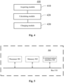
- Fig. 4 shows a schematic structural diagram of a battery charging apparatus provided according to some embodiments of the present application.
- a battery charging apparatus 400 includes:
- the calculating module 420 is specifically configured to:
- the calculating module 420 is further specifically configured to:
- the calculating module 420 is further specifically configured to:
- the calculating module 420 is further specifically configured to:
- the charging demand parameter includes at least one of the following parameters:
- the actual operation state information of the battery includes: a current temperature of the battery, an SOC of the battery, and a capacity of the battery;
- the battery also includes a determining module, which is configured to: determine that the actual operation state information of the battery can be acquired.
- the determining module is specifically configured to: determine that the current temperature of the battery is within a preset temperature range.
- the battery charging apparatus also includes a processing apparatus, which is configured to:
- the processing apparatus is further configured to:
- the present application also provides a battery management system, which includes the battery charging apparatus as shown in Fig. 3 .
- Other details of the battery charging device included in the battery management system according to the embodiment of the present application are similar to the methods according to the embodiments of the present application described above in conjunction with Fig. 2 , which will not be repeated here.
- the embodiments of the present application also provide a charging pile, which includes the battery charging apparatus as shown in Fig. 3 .
- Other details of the battery charging device included in the charging pile according to the embodiment of the present application are similar to the methods according to the embodiments of the present application described above in conjunction with Fig. 2 , which will not be repeated here.
- Fig. 5 is a schematic diagram illustrating a hardware structure 500 of a battery charging device according to an embodiment of the present application.
- the battery charging device 500 in the embodiment includes: a processor 501, a memory 502, a communication interface 503, and a bus 510.
- the processor 501, the memory 502, and the communication interface 503 are connected to each other through the bus 510 and complete communication with each other.
- the above-mentioned processor 501 may include a central processing unit (CPU), or a specific integrated circuit (ASIC), or may be configured to implement one or more integrated circuits according to the embodiments of the present application.
- CPU central processing unit
- ASIC specific integrated circuit
- the memory 502 may include a mass storage for data or instructions.
- the memory 502 may include an HDD, a floppy disk drive, a flash memory, an optical disk, a magneto-optical disk, a magnetic tape or a universal serial bus (USB) drive, or a combination of two or more of these.
- the memory 502 may include a removable or non-removable (or fixed) medium.
- the memory 502 may be internal or external to the battery charging device 500.
- the memory 502 is a non-volatile solid state memory.
- the memory 502 includes a read-only memory (ROM).
- the ROM may be a mask-programmed ROM, a programmable ROM (PROM), an erasable PROM (EPROM), an electrically erasable PROM (EEPROM), an electrically rewritable ROM (EAROM) or a flash memory, or a combination of two or more of these.
- PROM programmable ROM
- EPROM erasable PROM
- EEPROM electrically erasable PROM
- EAROM electrically rewritable ROM
- flash memory or a combination of two or more of these.
- the communication interface 503 is mainly used to implement communication between various modules, devices, units, and/or devices in the embodiments of the present application.
- the bus 510 includes hardware, software, or both, and couples components of the battery charging device 500 to each other.
- the bus may include an accelerated graphics port (AGP) or other graphics buses, an enhanced industry standard architecture (EISA) bus, a front side bus (FSB), a hypertransport (HT) interconnect, an industry standard architecture (ISA) Bus, an unlimited bandwidth interconnect, a low pin count (LPC) bus, a memory bus, a microchannel architecture (MCA) bus, a peripheral component interconnect (PCI) bus, a PCI-Express (PCI-X) bus, a serial advanced technology An accessory (SATA) bus, a Video Electronics Standards Association local (VLB) bus, or other suitable bus, or a combination of two or more of these.
- the bus 510 may include one or more buses. Although specific buses are described and illustrated in the embodiments of this application, this application contemplates any suitable bus or interconnect.
- the battery charging device 500 shown in Fig. 5 may be implemented to include: the processor 501, the memory 502, the communication interface 503, and the bus 510.
- the processor 501, the memory 502, and the communication interface 503 are connected through the bus 510 and complete communication with each other.
- the memory 502 is configured to store a program code; the processor 501 reads the executable program code stored in the memory 502 to run a program corresponding to the executable program code, to execute the battery charging method according to any one of the embodiments of the present application, thereby implementing the battery charging method and the device described in conjunction with Fig. 2 to Fig. 4 .
- the embodiments of the present application also provide a computer storage medium, where the computer storage medium has a computer program instruction stored thereon; where the computer program instruction, when being executed by a processor, implements the battery charging method as provided by the embodiments of the present application.
- the functional block(s) shown in the block diagrams described above may be implemented in hardware, software, firmware, or a combination thereof.
- the functional block(s) may be, for example, an electronic circuit, an application specific integrated circuit (ASIC), a suitable firmware, a plug-in, a function card or the like.
- ASIC application specific integrated circuit
- elements of the embodiments of the present disclosure are programs or code segments used to perform required tasks.
- the programs or code segments may be stored in a machine-readable medium or transmitted over a transmission medium or a communication link via data signals carried in carriers.
- the "machine-readable medium” may include any medium capable of storing or transmitting information.
- Examples of the machine-readable medium include an electronic circuit, a semiconductor memory device, a ROM, a flash memory, an erasable ROM (EROM), a floppy disk, a CD-ROM, an optical disk, a hard disk, a fiber medium, a radio frequency (RF) link, and the like.
- the code segments may be downloaded via a computer network, such as the Internet, an intranet, or the like.
Landscapes
- Engineering & Computer Science (AREA)
- Power Engineering (AREA)
- Transportation (AREA)
- Mechanical Engineering (AREA)
- Life Sciences & Earth Sciences (AREA)
- Sustainable Development (AREA)
- Sustainable Energy (AREA)
- Charge And Discharge Circuits For Batteries Or The Like (AREA)
- Health & Medical Sciences (AREA)
- General Health & Medical Sciences (AREA)
- Medical Informatics (AREA)
Description
- The application relates to the field of new energy, in particular, to a battery charging method, an apparatus, a device, a battery management system and a charging pile.
- Nowadays, with the gradual consumption of non-renewable energy such as oil and the urgent demand for environmental protection, the development of the new energy industry has attracted much attention. Battery is one of the key and core technologies in the new energy industry. In recent years, new energy vehicles using rechargeable batteries as the power source have been developed very fast, which have a gradually expanding proportion in the world's vehicles and are widely used in large and medium-sized cities. They are also an important part of the development of electric vehicle industry and the realization of advanced manufacturing industry.
- In the current electric vehicles, mostly, charging batteries are charged by using charging piles. However, with the development of the industry of the electric vehicles, users have higher demands for the intelligence of the electric vehicle. For example, when a user connects a charging device to the electric vehicle for charging, the user wants to know information regarding: how long it takes to fully charge the vehicle, how long it takes to charge the vehicle to a target electricity amount, how much electricity the vehicle can be charged in a limited charging time, and a distance the vehicle can travel when it is charged to the target electricity amount, and the like.
- As the user is always a passive receiver during the process of the service, he/she cannot realize personalized smart charging according to his/her own demands, for example, information such as a charging time at his/her disposal or mileage. In order to help the user to arrange his/her time reasonably, the realization of personalized smart charging is an urgent problem.
- Document
US 6281663B1 discloses a battery charging method in which a reduction in charging time is achieved while suppressing any deterioration in the lifetime of the battery. A battery temperature increase margin is determined from the battery temperature at charge commencement and the upper limit value of the battery temperature. Moreover, the target charging capacity is determined from the initial state of charge at charge commencement and the target state of charge at charge completion. Furthermore, a value of an upper limit of the battery temperature increase is determined from these. Then, the battery charge current maximum value is set by map referral based on the value of an upper limit of the battery temperature increase such that the temperature of the battery during charging does not exceed the upper limit value. A driver performs the battery charging using a charge current value that has been set on the basis of the battery charge maximum value. - Document
US 9128510B2 - Document
CN 103915869A discloses an electric car intelligent charging system and method on the basis of a mobile device and belongs to the technical field of electric car charging positive intelligent control. The system comprises a power grid management center, a station level management server, the mobile device, a charging device and a power battery. The station level management server comprises a data input module, a data processing module, a data feedback module and a historical data memory module and is used for calculating, solving and achieving the real-time optimum order charging scheme, outputting specific charging orders to the charging device and the mobile device and feeding back the charging information. According to the method, the local optimum greedy algorithm is used for solving the real-time optimum order charging scheme, the user interaction character is achieved, and the order charging scheme of an electric car is obtained by carrying out data mining and predicting on the user data and the power grid data and carrying out performance analysis on the power batteryEP2505421 relates to a method for optimal planning of electric power demand, including: receiving relevant data from one or more sources, and determining an optimized SCPEV load and optimal charging schedule for a node by applying an operations research technique on the relevant data. - The embodiments of the present application provide a battery charging method, an apparatus, a device, a battery management system and a charging pile, which can implement personalized smart charging for different users.
- According to one aspect of the embodiments of the present application, a battery charging method is provided in accordance with claim 1.
- According to another aspect of the embodiments of the present application, a battery charging apparatus is provided in accordance with
claim 11. - According to yet another aspect of the embodiments of the present application, a battery management system is provided, where the system includes the battery charging apparatus as provided by the embodiments of the present application.
- According to yet another aspect of the embodiments of the present application, a charging pile is provided, where the charging pile includes the battery charging apparatus as provided by the embodiments of the present application.
- According to the battery charging method, the apparatus, the device, the battery management system and the charging pile provided by the embodiments of the present application, the target charging scheme for charging the battery is calculated according to the acquired charging demand parameter which is set by the user and the actual operation state information of the battery, and then the charging request is transmitted to the charging device according to the target charging scheme for charging the battery, where, by setting the target charging scheme according to the charging demand parameter set by the user, the personalized smart charging is realized for different users.
- Features, advantages, and technical advantages of the exemplary embodiments of the present application will be described below with reference to the drawings.
-
Fig. 1 shows a schematic architectural diagram of a battery charging system according to some embodiments of the present application; -
Fig. 2 shows a schematic flowchart of a battery charging method according to some embodiments of the present application; -
Fig. 3 shows a schematic flowchart of a battery charging method according to some other embodiments of the present application; -
Fig. 4 shows a schematic structural diagram of a battery charging apparatus according to some embodiments of the present application; and -
Fig. 5 shows a structural diagram of an exemplary hardware architecture of a battery charging device according to some embodiments of the present application. - Implementations of the present application are described in further detail below with reference to the drawings and embodiments. The detailed description and drawings of the following embodiments are used to exemplarily illustrate the principle of the present application, but they cannot be used to limit the scope of the present application, that is, the present application is not limited to the described embodiments.
- It is to be noted that relational terms such as first, second, and the like are used herein solely to distinguish one entity or operation from another entity or operation without necessarily requiring or implying any actual such relationship or order between such entities or operations. Moreover, the terms "include", "including", or any other variation thereof, are intended to cover a non-exclusive inclusion, such that a process, method, article or device that includes a series of elements does not include only those elements but may include other elements not explicitly listed or inherent to such process, method, article or device. An element preceded by "include..." does not, without more constraints, preclude the existence of additional identical elements in the process, method, article or device that includes the element.
- For a better understanding of the present application, a battery charging method, an apparatus, a device, a medium, a battery management system and a charging pile according to embodiments of the present application will be described in detail with reference to the drawings. It is to be noted that these embodiments are not intended to limit the scope disclosed by the present application.
-
Fig. 1 shows a schematic architectural diagram of abattery charging system 100 according to some embodiments of the present application. As shown inFig. 1 , the battery charging system includes aterminal 10 of a user, avehicle 11 installed with a battery to be charged, and acharging pile 12. When the user wants to charge thevehicle 11, the user inputs a charging demand parameter through theterminal 10. Theterminal 10 transmits the charging demand parameter set by the user to thevehicle 11. The battery management system in thevehicle 11 receives the charging demand parameter, and calculates a target charging scheme for charging the battery according to the charging demand parameter and acquired actual operation state information of the battery. After the target charging scheme is calculated by the battery management system, a charging request is transmitted to thecharging device 12 according to the target charging scheme, so that the charging device charges the battery of thevehicle 11 according to the target charging scheme. The charging device and the vehicle may be connected through a charging gun (not shown inFig. 1 ). - According to the battery charging system provided in the embodiment of the present application, the charging demand parameter set by the user is utilized to determine the target charging scheme that is actually used for charging the battery, thereby realizing personalized charging according to the demands of the user.
-
Fig. 2 shows a flowchart of a battery charging method applied to a battery management system side according to some embodiments of the present application. As shown inFig. 2 , thebattery charging method 200 applied to the battery management system side in the embodiment of the present application includes the following steps:
S210: acquiring a charging demand parameter set by a user. - As shown in
Fig. 3 , the user first parks the electric vehicle next to the charging device, where the charging gun may or may not be inserted into the charging device. The user may set one or more charging demand parameters through a charging demand parameter setting interface. The charging demand parameter setting interface may be on a display in the vehicle, in a mobile phone application (Application, APP) or on an additional control panel in the vehicle. - The charging demand parameter is a charging parameter associated with the charging demands of the user. As an example, the charging demand parameter includes at least one of the following parameters: a charging time at the user's disposal, mileage required by the user, a state of charge (State of Charge, SOC) of the battery required by the user, a charging fee at the user's disposal, a type of charging mode, a charging price.
- It should be noted that, the charging demand parameter setting interface may display multiple charging demand parameters for the user to set, but the user may set one or more input values of the charging demand parameters according to his/her own demands. That is, the charging demand parameter set by the user includes the type of charging demand parameter selected by the user and the user input value corresponding to that charging demand parameter.
- In some embodiments of the present application, if the charging prices of charging devices from different brands and companies are not significantly different, that is, the cost per kilowatt-hour is not significantly different, a charging price may be set in advance in the battery management system to facilitate the calculation of the target charging scheme.
- S220: calculating a target charging scheme for charging the battery according to the charging demand parameter and acquired actual operation state information of a battery.
- As an example, still referring to
Fig. 3 , after the user sets the charging demand parameter through the terminal according to his/her actual situation, the terminal transmits an instruction of the scheme planning and the charging demand parameter to the battery management system (Battery Management System, BMS). The BMS plans the target charging scheme for charging the battery according to the actual operation state information of the battery and the charging demand parameter set by the user. - The target charging scheme includes at least one of the following considerations: a charging waiting time for the user, increasable endurance mileage of the battery, an SOC of the battery that can be increased, a charging fee to be paid by the user.
- The charging waiting time is a charging time required for the battery to reach a certain SOC from the current SOC, which may also be referred to as the remaining charging time.
- As an example, the actual operation state information of the battery includes: a current temperature of the battery, a current SOC of the battery, and a capacity of the battery. Therefore, the charging waiting time may be calculated according to the increasable SOC of the battery, the current temperature of the battery, the current SOC of the battery, a preset corresponding relationship between a charging demand current with the temperature and the SOC, and an acquired charging temperature rising rate of the battery.
- Specifically, first, a charging current value of the battery is determined according to the current temperature of the battery, the current SOC of the battery, and the preset corresponding relationship between the charging demand current with the temperature and the SOC.
- Then, the charging temperature rising rate of the battery is determined according to the current SOC of the battery, the current temperature of the battery and the corresponding relationship between the temperature changing rate, the temperature, and the SOC.
- Next, a search is made for a changing path of the SOC and the battery temperature during the charging process according to the charging current and the charging temperature rising rate. A temperature at the next moment is calculated according to the charging temperature rising rate of the battery, and a current value at the next moment is calculated according to a current output. The time during which the temperature and the current change is accumulated until the target SOC is obtained by calculation. The accumulated time is outputted as the charging waiting time. The target SOC is a sum of the current SOC of the battery and the increasable SOC of the battery.
- In some embodiments of the present application, the charging current value of the battery may be corrected by using an actual current which is outputted by the charging device. At the beginning of the charging, the calculation is performed according to the charging request current of the BMS. During the charging process, the actual charging current during a period of time is extracted, a future charging current of the BMS is corrected according to a proportional relationship between the actual output current of the charging device and the charging request current, and the remaining charging time is estimated using that coefficient.
- In some embodiments of the present application, the actual operation state information of the battery further includes at least one of the following information: a current state of health (SOH) of the battery, a current voltage of the battery, internal resistance of the battery, working information of a heating system of the battery, working information of a cooling system of the battery, mileage of the battery when fully charged.
- In some embodiments of the present application, according to the working information of the internal heating system of the battery, the working information of the cooling system of the battery, and the energy conservation law, the charging temperature rising rate of the battery may be estimated to calculate the remaining charging time.
- In some embodiments of the present application, the collected current and the current voltage of the battery may also be used to estimate the current SOC of the battery, and then the current SOC is converted to an open circuit voltage to calculate the remaining charging time.
- In some embodiments of the present application, the capacity of the battery may be corrected using the internal resistance and the current state of health (State of Health, SOH) of the battery, so as to correct the charging waiting time.
- In the embodiment of the present application, the increasable endurance mileage of the battery may be calculated according to the increasable SOC of the battery. Specifically, the corresponding endurance mileage by consuming the increasable SOC of the battery is estimated according to the mileage of the battery when fully charged. Since the consumption of power is different at high and low battery levels, the mileage may be corrected through a weighting factor. The weighting factor is determined by fitting mileage corresponding to the SOC consumption in different intervals.
- Therefore, if the target charging scheme includes the increasable endurance mileage of the battery, the actual operation state information of the battery may also include the corresponding mileage when the battery is fully charged.
- In the embodiment of the present application, the charging fee to be paid the user may be calculated according to the increasable SOC of the battery and the price corresponding to the charging device.
- Since the actual operation state information of the battery is information required for calculating the target charging scheme, before step S220, the battery charging method further includes the following step:
S211: determining that the actual operation state information of the battery can be acquired. - In the embodiment of the present application, if the actual operation state information of the battery cannot be acquired, the user is prompted to perform checking.
- As an example, the current temperature of the battery is important actual operation state information, if the temperature information of the battery cannot be acquired, the user is prompted to check whether the temperature collection of the battery has failed.
- If it is determined that the current temperature of the battery can be acquired, then it should be further determined whether the current temperature of the battery is within a preset temperature range. If the current temperature of the battery is not within the preset temperature range, the charging request is not transmitted to the charging device and the user is prompted to perform checking.
- In the embodiment of the present application, if the user sets a plurality of charging demand parameters, since the user cannot determine whether the plurality of charging demand parameters can be satisfied with each other, the battery management system would calculate an optimal target charging scheme that can satisfy the demands of the user according to the charging demand parameters set by the user.
- In the embodiment of the present application, S220 includes the following steps: S2201: if the charging demand parameters do not include a charging demand parameter associated with a charge capacity of the battery, calculating the target charging scheme based on a preset charging threshold and the actual operation state information.
- As an example, if the user only sets a charging mode that is irrelevant to the charge capacity, the battery management system would plan the increasable SOC of the battery as the SOC corresponding to the preset charging threshold.
- Then, the charging waiting time is calculated according to the target SOC corresponding to the charging threshold and the actual operation state information of the battery, of which the calculation manner will not be repeated here.
- Finally, the charging fee to be paid by the user is calculated according to the charging threshold, and the increasable endurance mileage of the battery corresponding to the charging threshold may be calculated according to the mileage of the battery when fully charged.
- S2202: if the charging demand parameters include only one charging demand parameter associated with the charge capacity of the battery, calculating the target charging scheme based on the one charging demand parameter associated with the charge capacity and the actual operation state information.
- In the embodiment of the present application, if the only one charging demand parameter associated with the charge capacity of the battery is not the charging time at the user's disposal, the increasable SOC for the user is first determined according to the only one charging demand parameter associated with the charge capacity of the battery.
- Then, information, such as the charging waiting time, the increasable endurance mileage of the battery and the charging fee to be paid by the user, is calculated according to the increasable SOC of the battery and the actual operation state information of the battery.
- If the only one charging demand parameter associated with the charge capacity of the battery is the charging time at the user's disposal, the charging time at the user's disposal is taken as the charging waiting time for the user. Then the increasable SOC of the battery is determined according to the current temperature of the battery, the current SOC of the battery, the preset corresponding relationship between a charging demand current with the temperature and the SOC, and the acquired charging temperature rising rate of the battery.
- Then information such as the increasable endurance mileage of the battery and the charging fee to be paid by the user is calculated according to the increasable SOC of the battery.
- S2203: if the charging demand parameters include a plurality of candidate parameters associated with the charge capacity of the battery, selecting any one candidate parameter of the plurality of candidate parameters as the current parameter.
- As an example, if the user sets three candidate parameters associated with the charge capacity of the battery, including: a charging time at the user's disposal t, mileage required by the user s, and a state of charge of the battery required by the user m. A user input value of t is 30 minutes (min), a user input value of s is 50 kilometers (km), and a user input value of m is 90%. As a specific example, t is selected as the current parameter from s, t and m.
- S2204: calculating a calculation value of each of other parameters under a condition of the current parameter according to the current parameter and the actual operation state information, where the other parameters are parameters other than the current parameter of the plurality of candidate parameters.
- As an example, the calculation value of m and the calculation value of s under a condition of 30 min may be calculated according to the user input value of t which is 30 min and the actual operation state information of the battery.
- S2205: if, for any other parameter of all the other parameters, the calculation value of the other parameter is less than or equal to user input value corresponding to the other parameter, taking the current parameter as a target charging demand parameter;
- if there is only one target other parameter among all the other parameters, taking the target other parameter as the target charging demand parameter, where a calculation value of the target other parameter is greater than a user input value corresponding to the target other parameter;
- if there are a plurality of target other parameters among all of the other parameters, updating the current parameter with any one of the plurality of target other parameters, until the target charging demand parameter is selected from the plurality of candidate parameters.
- In the above example, if, under the condition of 30 min, the calculation value of m is 80% and the calculation value of s is 45 km, it represents that the charging time at the user's disposal, which is 30 min, is the parameter that would be first reached, that is, t is taken as the target charging demand parameter.
- if, under the condition of 30 min, the calculation value of m is 80% and the calculation value of s is 60 km, then the target other parameter is s, that is, s is taken as the target charging demand parameter.
- if, under the condition of 30 min, the calculation value of m is 100% and the calculation value of s is 60 km, then the target other parameters include m and s. Then, the current parameter is updated with any one parameter selected from s and m, and then the process proceeds to step S2204, until the target charging demand parameter is determined.
- In some embodiments of the present application, if the charging demand parameters set by the user include the state of charge of the battery required by the user, the SOC required by the user and the actual operation state information of the battery may first be used to calculate the remaining charging time. If any one parameter of the charging waiting time for the user, the increasable endurance mileage of the battery and the charging fee to be paid by the user has reached the input value set by the user before the SOC required by the user is calculated to be reached, then the charging demand parameter that has reached the user input value is taken as the target charging demand parameter. The user input value is a numerical value that is set by the user for the charging demand parameter.
- S2206: calculating the target charging scheme based on the target charging demand parameter and the actual operation state information.
- As an example, the target charging demand parameter is the charging time at the user's disposal which is 30 min, then the increasable SOC of the battery in the target charging scheme is calculated according to the charging time at the user's disposal (30 min) and the actual operation state information of the battery. Finally, the increasable endurance mileage of the battery and the charging fee to be paid by the user are calculated according to the increasable SOC of the battery.
- In the embodiment of the present application, the target charging demand parameter is selected from the charging demand parameters set by the user, thus, the optimal charging scheme that satisfies many aspects of the user's demands can be calculated, which improves the user experience.
- In the embodiment of the present application, since information such as the charging current and the temperature changing rate of the battery is different in different charging modes, the charging planning schemes obtained in different charging modes are different according to the same charging demand parameter and the actual operation state information of the battery.
- In some embodiments of the present application, if the user knows well about the charging modes, then the user may preset the type of charging mode. Then the battery management system takes the type of charging mode set by the user as the target charging mode, calculates the charging planning scheme in the target charging mode according to the charging demand parameter set by the user and the actual operation state information of the battery, and takes the charging planning scheme in the target charging mode as the target charging scheme.
- According to the battery charging method provided by the embodiment, the target charging scheme is calculated using the charging mode set by the user, which not only satisfies the charging demands of the user, but also reduces the calculation time and improves the charging speed.
- In some embodiments of the present application, still referring to
Fig. 3 , if the user does not set the type of charging mode, a charging planning scheme in each charging mode of the preset plurality of charging modes is calculated respectively according to the charging demand parameter and the actual operation state information. As an example, the preset plurality of charging modes include a fast charging mode, a slow charging mode, and a healthy charging mode. - In the embodiment of the present application, if the charging demand parameters set by the user do not include a parameter associated with the charge capacity of the battery, then the charging planning scheme in each charging mode is calculated based on a manner similar to step S2201.
- If the charging demand parameters set by the user include only one parameter associated with the charge capacity of the battery, then the charging planning scheme in each charging mode is calculated based on a method similar to step S2202.
- If the charging demand parameters set by the user include a plurality of candidate parameters associated with the charge capacity of the battery, then the target charging demand parameter in each charging mode is selected based on the manner according to step S2203 to step S2205. Finally, the charging planning scheme in each charging mode is calculated based on the target charging demand parameter in each charging mode and the actual operation state information of the battery.
- Still referring to
Fig. 3 , after the charging planning scheme in each charging mode is acquired, the charging planning scheme in each charging mode is transmitted to the terminal of the user. The terminal of the user displays the charging planning scheme in each charging mode to the user. The user selects the target charging mode from the plurality of charging modes according to the charging planning scheme in each charging mode. - After the target charging mode is determined by the user, an instruction is transmitted to the battery management system. The battery management system takes the acquired charging planning scheme in the target charging mode as the target charging scheme.
- If the user has not selected the charging mode during a preset period of time, a charging planning scheme in a preset charging mode of the plurality of charging modes is taken as the target charging scheme. As an example, the preset period of time is 30s, and the preset charging mode is the healthy charging mode.
- According to the battery charging method provided by the embodiment of the present application, the charging planning schemes in the plurality of charging modes are calculated, so that the user can select the charging mode as desire according to the more intuitive information in the charging planning scheme, which further satisfies the charging demands of the user and facilitates the user's operation.
- Still referring to
Fig. 3 , in some embodiments of the present application, after the planning information for the charging usage parameters is determined and before the planning information is used for charging the battery, according to the battery charging method, it is required to perform self-check on the battery management system. Specifically, before the charging of the battery, the battery charging method further includes:
S221: determining that the charging device is connected to the battery. - As shown
Fig. 3 , if the charging device is not connected to the vehicle installed with the battery, then the user is prompted to connect the charging device to the vehicle. If it is determined that the charging device is already connected to the vehicle installed with battery, then the user it prompted to perform charging based on the target charging scheme, that is, the method proceeds to S230. - S230: transmitting a first charging request to a charging device according to the target charging scheme, so that the charging device charges the battery according to the first charging request.
- In the embodiment of the present application, after the target charging scheme is determined, the charging request is continuously transmitted to the charging device according to the target charging scheme, so as to implement the charging of the battery by the charging device.
- According to the battery charging method provided by the embodiment of the present application, the smart charging of the battery according to the user's demands is realized, which facilitates the user to arrange his/her time reasonably and provides good user experience.
- In some embodiments of the present application, in order to further accommodate the user's demands, the battery charging method further includes:
S240: determining that the charging of the battery is completed according to the target charging scheme. - In the embodiment of the present application, during the process of transmitting the charging request to the charging device, it is determined whether the charging of the battery is completed according to the target charging scheme. Referring
Fig. 3 , if the charging of the battery is completed, then it is determined whether the user is in the vehicle installed with the battery. If the user is in the vehicle, then the transmitting the charging request to the charging device is stopped, and feedback information of charging completion is transmitted to the user to prompt the completion of the charging for the user. If the user is not in the vehicle, then the method proceeds to S250. - S250: determining that the user is not in vehicle installed with the battery, and transmitting, to the terminal of the user, selection information for instructing the user to select to re-develop a charging scheme or to stop transmitting a charging request to the charging device, so that the user gives a feedback instruction according to the selection information.
- Still referring to
Fig. 3 , if the charging task has been completed within the time specified by the user, but the user has not returned to the vehicle, selection information is remotely transmitted to the user via a text message or an APP to prompt the user either to re-develop the plan or stop the action such as transmitting the charging request to the charging device. - S260: if the feedback instruction is received, re-developing a charging scheme or stopping transmitting the charging request to the charging device.
- In the embodiment of the present application, if the user feeds back that the current charging scheme is to be continued, then the target electricity amount in the original scheme is changed to 100%, and then the charging is performed according to the preset healthy charging mode.
- If the user feeds back that a new scheme is to be performed, then the user is required to prompt the redevelopment of the charging plan via a text message, an APP or other remote interaction manners.
- If the user feeds back that the transmitting the charging request to the charging device is to be stopped, then the transmitting the charging request to the charging device is stopped, that is, the charging is stopped.
- According to the battery charging method provided by the embodiment of the present application, the feedback instruction from the user is received, which can further enable the user to plan his/her own time reasonably.
- S270: if the feedback instruction is not received, determining that the charging demand parameter includes a first charging fee at the user's disposal, that is, the limit of the charging fee, and determining whether a second charging fee to be paid by the user reaches the first charging fee;
- if the second charging fee does not reach the first charging fee, transmitting a second charging request to the charging device based on a charging planning scheme in a preset charging mode of the plurality of charging modes, so that the charging device charges the battery according to the second charging request; and
- if the second charging fee reaches the first charging fee, stopping transmitting the second charging request to the charging device and notifying the user.
- The preset charging mode may be the healthy charging mode in the plurality of charging modes.
- If the charging demand parameters set by the user do not include the first charging fee at the user's disposal, then the transmitting the charging request to the user is stopped, that is, the charging is suspended to wait for an instruction from the user. When the user disconnects the charging device from the electric vehicle, the charging is stopped.
- According to the battery charging method provided by the embodiment of the present application, not only the charging can be performed according to the user's demands, but also the charging information can be fed back to the user in real-time, so that the user can further change the charging scheme, which is more convenient for the user. In addition, the information interaction between the battery charging system and the charging device is reduced, which ensures the security of the data of the battery in the vehicle and the user data.
-
Fig. 4 shows a schematic structural diagram of a battery charging apparatus provided according to some embodiments of the present application. As shown inFig. 4 , abattery charging apparatus 400 includes: - an acquiring
module 410, configured to acquire a charging demand parameter set by a user; - a calculating
module 420, configured to calculate, according to the charging demand parameter and acquired actual operation state information of a battery, a target charging scheme for charging the battery; and - a
charging module 430, configured to transmit, according to the target charging scheme, a first charging request to a charging device, so that the charging device charges the battery according to the first charging request. - In the embodiment of the present application, the calculating
module 420 is specifically configured to: - calculate a charging planning scheme in each charging mode of a plurality of charging modes respectively according to the charging demand parameter and the actual operation state information;
- transmit the charging planning scheme in each charging mode to a terminal of the user, so that the user selects a target charging mode from the plurality of charging modes according to the charging planning scheme in each charging mode;
- take a charging planning scheme in the target charging mode as the target charging scheme.
- In the embodiment of the present application, the calculating
module 420 is further specifically configured to: - acquire a type of charging mode set by the user, and take a charging mode of the set type as a target charging mode;
- calculate a charging planning scheme in the target charging mode according to the charging demand parameters and the actual operation state information, and take the charging planning scheme in the target charging mode as the target charging scheme.
- In the embodiment of the present application, the calculating
module 420 is further specifically configured to: - if the charging demand parameters do not include a charging demand parameter associated with a charge capacity of the battery, calculate the target charging scheme based on a preset charging threshold and the actual operation state information;
- if the charging demand parameters include only one charging demand parameter associated with the charge capacity of the battery, calculate the target charging scheme based on the one charging demand parameter associated with the charge capacity and the actual operation state information.
- In the embodiment of the present application, the calculating
module 420 is further specifically configured to: - if the charging demand parameters include a plurality of candidate parameters associated with the charge capacity of the battery, select any one candidate parameter of the plurality of candidate parameters as a current parameter;
- calculate a calculation value of each of other parameters with the current parameter being a condition according to the current parameter and the actual operation state information, where the other parameters are parameters other than the current parameter of the plurality of candidate parameters;
- if, for any other parameter of all the other parameters, the calculation value of the other parameter is less than or equal to user input value corresponding to the other parameter, take the current parameter as a target charging demand parameter;
- if there is only one target other parameter among all of the other parameters, take the target other parameter as the target charging demand parameter, where a calculation value of the target other parameter is greater than a user input value corresponding to the target other parameter;
- if there are a plurality of target other parameters among all of the other parameters, update the current parameter with any one of the plurality of target other parameters, until the target charging demand parameter is selected from the plurality of candidate parameters;
- calculate the target charging scheme according to the target charging demand parameter and the actual operation state information.
- In the embodiment of the present application, the charging demand parameter includes at least one of the following parameters:
- a charging time at the user's disposal, mileage required by the user, a state of charge of the battery required by the user, a charging fee at the user's disposal, a type of charging mode, a charging price;
- the target charging scheme includes at least one of the following considerations:
a charging waiting time for the user, increasable endurance mileage of the battery, an increasable SOC of the battery, a charging fee to be paid by the user. - In the embodiment of the present application, the actual operation state information of the battery includes: a current temperature of the battery, an SOC of the battery, and a capacity of the battery; and
- the actual operation state information of the battery further includes at least one of the following information:
- an current SOH of the battery, a current voltage of the battery, an internal resistance of the battery, working information of a heating system of the battery, working information of a cooling system of the battery, mileage of the battery when fully charged.
- In the embodiment of the present application, the battery also includes a determining module, which is configured to:
determine that the actual operation state information of the battery can be acquired. - In the embodiment of the present application, the determining module is specifically configured to:
determine that the current temperature of the battery is within a preset temperature range. - In the embodiment of the present application, the battery charging apparatus also includes a processing apparatus, which is configured to:
- determine that the charge of the battery is completed according to the target charging scheme;
- determine that the user is not in vehicle installed with the battery in located, and transmit, to the terminal of the user, selection information for instructing the user to select to re-develop a charging scheme or to stop transmitting a charging request to the charging device, so that the user gives a feedback instruction according to the selection information;
- if the feedback instruction is received, re-develop a charging scheme or stop transmitting the charging request to the charging device.
- In the embodiment of the present application, the processing apparatus is further configured to:
- if the feedback instruction is not received, determine that the charging demand parameter includes a first charging fee at the user's disposal, and determine whether a second charging fee to be paid by user reaches the first charging fee;
- if the second charging fee does not reach the first charging fee, transmit a second charging request to the charging device based on a charging planning scheme in a preset charging mode of the plurality of charging modes, so that the charging device charges the battery according to the second charging request; and
- if the second charging fee reaches the first charging fee, stop transmitting the second charging request to the charging device.
- Other details of the battery charging device according to the embodiment of the present application are similar to the methods according to the embodiments of the present application described above in conjunction with
Fig. 2 , which will not be repeated here. - The present application also provides a battery management system, which includes the battery charging apparatus as shown in
Fig. 3 . Other details of the battery charging device included in the battery management system according to the embodiment of the present application are similar to the methods according to the embodiments of the present application described above in conjunction withFig. 2 , which will not be repeated here. - The embodiments of the present application also provide a charging pile, which includes the battery charging apparatus as shown in
Fig. 3 . Other details of the battery charging device included in the charging pile according to the embodiment of the present application are similar to the methods according to the embodiments of the present application described above in conjunction withFig. 2 , which will not be repeated here. - The battery charging method and the apparatus described in conjunction with
Fig. 2 to Fig. 4 according to the embodiments of the present application may be implemented through a battery charging device.Fig. 5 is a schematic diagram illustrating ahardware structure 500 of a battery charging device according to an embodiment of the present application. - As shown in
Fig. 5 , thebattery charging device 500 in the embodiment includes: aprocessor 501, amemory 502, acommunication interface 503, and a bus 510. Theprocessor 501, thememory 502, and thecommunication interface 503 are connected to each other through the bus 510 and complete communication with each other. - Specifically, the above-mentioned
processor 501 may include a central processing unit (CPU), or a specific integrated circuit (ASIC), or may be configured to implement one or more integrated circuits according to the embodiments of the present application. - The
memory 502 may include a mass storage for data or instructions. By way of example instead of limitation, thememory 502 may include an HDD, a floppy disk drive, a flash memory, an optical disk, a magneto-optical disk, a magnetic tape or a universal serial bus (USB) drive, or a combination of two or more of these. Where appropriate, thememory 502 may include a removable or non-removable (or fixed) medium. Where appropriate, thememory 502 may be internal or external to thebattery charging device 500. In a particular embodiment, thememory 502 is a non-volatile solid state memory. In a particular embodiment, thememory 502 includes a read-only memory (ROM). Where appropriate, the ROM may be a mask-programmed ROM, a programmable ROM (PROM), an erasable PROM (EPROM), an electrically erasable PROM (EEPROM), an electrically rewritable ROM (EAROM) or a flash memory, or a combination of two or more of these. - The
communication interface 503 is mainly used to implement communication between various modules, devices, units, and/or devices in the embodiments of the present application. - The bus 510 includes hardware, software, or both, and couples components of the
battery charging device 500 to each other. By way of example instead of limitation, the bus may include an accelerated graphics port (AGP) or other graphics buses, an enhanced industry standard architecture (EISA) bus, a front side bus (FSB), a hypertransport (HT) interconnect, an industry standard architecture (ISA) Bus, an unlimited bandwidth interconnect, a low pin count (LPC) bus, a memory bus, a microchannel architecture (MCA) bus, a peripheral component interconnect (PCI) bus, a PCI-Express (PCI-X) bus, a serial advanced technology An accessory (SATA) bus, a Video Electronics Standards Association local (VLB) bus, or other suitable bus, or a combination of two or more of these. Where appropriate, the bus 510 may include one or more buses. Although specific buses are described and illustrated in the embodiments of this application, this application contemplates any suitable bus or interconnect. - That is, the
battery charging device 500 shown inFig. 5 may be implemented to include: theprocessor 501, thememory 502, thecommunication interface 503, and the bus 510. Theprocessor 501, thememory 502, and thecommunication interface 503 are connected through the bus 510 and complete communication with each other. Thememory 502 is configured to store a program code; theprocessor 501 reads the executable program code stored in thememory 502 to run a program corresponding to the executable program code, to execute the battery charging method according to any one of the embodiments of the present application, thereby implementing the battery charging method and the device described in conjunction withFig. 2 to Fig. 4 . - The embodiments of the present application also provide a computer storage medium, where the computer storage medium has a computer program instruction stored thereon; where the computer program instruction, when being executed by a processor, implements the battery charging method as provided by the embodiments of the present application.
- The functional block(s) shown in the block diagrams described above may be implemented in hardware, software, firmware, or a combination thereof. When implemented in hardware, the functional block(s) may be, for example, an electronic circuit, an application specific integrated circuit (ASIC), a suitable firmware, a plug-in, a function card or the like. When implemented in software, elements of the embodiments of the present disclosure are programs or code segments used to perform required tasks. The programs or code segments may be stored in a machine-readable medium or transmitted over a transmission medium or a communication link via data signals carried in carriers. The "machine-readable medium" may include any medium capable of storing or transmitting information. Examples of the machine-readable medium include an electronic circuit, a semiconductor memory device, a ROM, a flash memory, an erasable ROM (EROM), a floppy disk, a CD-ROM, an optical disk, a hard disk, a fiber medium, a radio frequency (RF) link, and the like. The code segments may be downloaded via a computer network, such as the Internet, an intranet, or the like.
- Although the present application has been described with reference to the preferred embodiments, various modifications may be made thereto and components thereof may be replaced with equivalents without departing from the scope of the present application, as indicated by the independent claims. In particular, as long as there is no structural conflict, the technical features mentioned in the embodiments can be combined in any manner. This application is not limited to the specific embodiments disclosed herein, instead, it includes all technical solutions that fall within the scope of the claims.
Claims (13)
- A battery charging method (200), comprising:acquiring (S210) one or more charging demand parameters set by a user;calculating, (S220) according to the charging demand parameters and acquired actual operation state information of a battery, a target charging scheme for charging the battery;transmitting, (S230) according to the target charging scheme, a first charging request to a charging device, so that the charging device charges the battery according to the first charging request;the battery charging method (200) is characterized in that the calculating (S220), according to the charging demand parameters and acquired actual operation state information of the battery, a target charging scheme for charging the battery comprises:selecting, when the charging demand parameters comprise a plurality of candidate parameters associated with the charge capacity of the battery, any one candidate parameter of the plurality of candidate parameters as a current parameter;calculating, according to the current parameter and the actual operation state information, a value of each of other parameters under a condition of the current parameter, wherein the other parameters are parameters other than the current parameter of the plurality of candidate parameters;taking the current parameter as a target charging demand parameter, when, for any other parameter of all the other parameters, the calculated value of the other parameter is less than or equal to a value input by the user corresponding to the other parameter;taking, when there is only one target other parameter among all of the other parameters, the target other parameter as the target charging demand parameter, wherein a calculated value of the target other parameter is greater than a value input by the user corresponding to the target other parameter;updating, when there are a plurality of target other parameters among all of the other parameters, the current parameter with any one of the plurality of target other parameters, until the target charging demand parameter is selected from the plurality of candidate parameters; andcalculating the target charging scheme according to the target charging demand parameter and the actual operation state information.
- The method according to claim 1, wherein, the calculating (S220), according to the charging demand parameters and acquired actual operation state information of the battery, a target charging scheme for charging the battery comprises:calculating, according to the charging demand parameters and the actual operation state information, a charging planning scheme in each charging mode of a plurality of preset charging modes respectively;transmitting the charging planning scheme in each charging mode to a terminal of the user, so that the user selects a target charging mode from the plurality of charging modes according to the charging planning scheme in each charging mode;taking a charging planning scheme in the target charging mode as the target charging scheme.
- The method according to claim 1, wherein, the calculating (S220), according to the charging demand parameters and acquired actual operation state information of the battery, a target charging scheme for charging the battery comprises:acquiring a type of charging mode set by the user, and taking a charging mode of the set type as a target charging mode;calculating, according to the charging demand parameters and the actual operation state information, a charging planning scheme in the target charging mode, and taking the charging planning scheme in the target charging mode as the target charging scheme.
- The method according to claim 1, wherein, the calculating (S220), according to the charging demand parameters and acquired actual operation state information of the battery, a target charging scheme for charging the battery comprises:calculating, when the charging demand parameters do not comprise a charging demand parameter associated with a charge capacity of the battery, the target charging scheme according to a preset charging threshold and the actual operation state information;calculating, when the charging demand parameters comprise only one charging demand parameter associated with the charge capacity of the battery, the target charging scheme according to the one charging demand parameter associated with the charge capacity and the actual operation state information.
- The method according to claim 1, wherein, the charging demand parameters comprise at least one of the following parameters:a charging time at the user's disposal, mileage required by the user, a state of charge of the battery required by the user, a charging fee at the user's disposal, a type of charging mode, a charging price;the target charging scheme comprises at least one of the following considerations:
a charging waiting time for the user, increasable endurance mileage of the battery, an increasable SOC of the battery, a charging fee to be paid by the user. - The method according to claim 1, wherein, the actual operation state information of the battery comprises: a current temperature of the battery, a current state of charge SOC of the battery, and a capacity of the battery; and
the actual operation state information of the battery further comprises at least one of the following information:
a current state of health SOH of the battery, a current voltage of the battery, an internal resistance of the battery, working information of a heating system of the battery, working information of a cooling system of the battery, mileage of the battery when fully charged. - The method according to claim 1, wherein, before the calculating (S220), according to the charging demand parameters and acquired actual operation state information of the battery, a target charging scheme for charging the battery, the method comprises:
determining that the actual operation state information of the battery can be acquired. - The method according to claim 7, wherein, the actual operation state information comprises a current temperature of the battery,
wherein, after the determining that the actual operation state information of the battery can be acquired and before the calculating (S220), according to the charging demand parameters and acquired actual operation state information of the battery, a target charging scheme for charging the battery, the method further comprises:
determining that the current temperature of the battery is within a preset temperature range. - The method according to claim 2, wherein, the method further comprises:determining that the charging of the battery is completed according to the target charging scheme;determining that the user is not in a vehicle installed with the battery, and transmitting, to the terminal of the user, selection information for instructing the user to select to re-develop a charging scheme or to stop transmitting a charging request to the charging device, so that the user gives a feedback instruction according to the selection information;re-developing a charging scheme or stopping transmitting a charging request to the charging device, when the feedback instruction is received.
- The method according to claim 9, wherein, the method further comprises:when the feedback instruction is not received, determining that the charging demand parameters comprise a first charging fee at the user's disposal, and determining whether a second charging fee to be paid by the user reaches the first charging fee;transmitting a second charging request to the charging device according to a charging planning scheme in a preset charging mode of the plurality of charging modes, when the second charging fee does not reach the first charging fee, so that the charging device charges the battery according to the second charging request; andstopping transmitting the second charging request to the charging device, when the second charging fee reaches the first charging fee.
- A battery charging apparatus (400), comprising:an acquiring module (410), configured to acquire (S210) one or more charging demand parameters set by a user;a calculating module (420), configured to calculate (S220), according to the charging demand parameters and acquired actual operation state information of a battery, a target charging scheme for charging the battery; anda charging module (430), configured to transmit (S230), according to the target charging scheme, a first charging request to a charging device, so that the charging device charges the battery according to the first charging request;the battery charging apparatus (400) is characterized in that the calculating module (420) is further configured to:select, when the charging demand parameters comprise a plurality of candidate parameters associated with the charge capacity of the battery, any one candidate parameter of the plurality of candidate parameters as a current parameter;calculate, according to the current parameter and the actual operation state information, a value of each of other parameters under a condition of the current parameter, wherein the other parameters are parameters other than the current parameter of the plurality of candidate parameters;take the current parameter as a target charging demand parameter, when, for any other parameter of all the other parameters, the calculated value of the other parameter is less than or equal to a value input by the user corresponding to the other parameter;take, when there is only one target other parameter among all of the other parameters, the target other parameter as the target charging demand parameter, wherein a calculated value of the target other parameter is greater than a value input by the user corresponding to the target other parameter;update, when there are a plurality of target other parameters among all of the other parameters, the current parameter with any one of the plurality of target other parameters, until the target charging demand parameter is selected from the plurality of candidate parameters; andcalculate the target charging scheme according to the target charging demand parameter and the actual operation state information.
- A battery management system, comprising the battery charging apparatus (400) according to claim 11.
- A charging pile, comprising the battery charging apparatus (400) according to claim 11.
Applications Claiming Priority (2)
| Application Number | Priority Date | Filing Date | Title |
|---|---|---|---|
| CN201811454861.1A CN111251928B (en) | 2018-11-30 | 2018-11-30 | Charging method, charging device, charging equipment, charging medium, battery management system and charging pile |
| PCT/CN2019/122151 WO2020108639A1 (en) | 2018-11-30 | 2019-11-29 | Charging method, apparatus and device, medium, battery management system and charging pile |
Publications (3)
| Publication Number | Publication Date |
|---|---|
| EP3760474A1 EP3760474A1 (en) | 2021-01-06 |
| EP3760474A4 EP3760474A4 (en) | 2021-06-23 |
| EP3760474B1 true EP3760474B1 (en) | 2024-09-04 |
Family
ID=70852447
Family Applications (1)
| Application Number | Title | Priority Date | Filing Date |
|---|---|---|---|
| EP19891484.8A Active EP3760474B1 (en) | 2018-11-30 | 2019-11-29 | Charging method, apparatus and device, medium, battery management system and charging pile |
Country Status (7)
| Country | Link |
|---|---|
| US (1) | US11590857B2 (en) |
| EP (1) | EP3760474B1 (en) |
| CN (1) | CN111251928B (en) |
| DK (1) | DK3760474T3 (en) |
| ES (1) | ES2993054T3 (en) |
| PT (1) | PT3760474T (en) |
| WO (1) | WO2020108639A1 (en) |
Families Citing this family (46)
| Publication number | Priority date | Publication date | Assignee | Title |
|---|---|---|---|---|
| CN110896233B (en) * | 2018-09-12 | 2021-07-30 | 宁德时代新能源科技股份有限公司 | battery management system |
| JP7063798B2 (en) * | 2018-12-21 | 2022-05-09 | トヨタ自動車株式会社 | Charging system |
| CN110988565B (en) * | 2019-12-24 | 2021-12-07 | 重庆国翰能源发展有限公司 | Self-checking method for one-machine four-pile charging pile system |
| CN113547955B (en) * | 2020-04-23 | 2023-06-16 | 宁德时代新能源科技股份有限公司 | Battery charging control method, device, battery management system and medium |
| US12068603B2 (en) * | 2020-09-21 | 2024-08-20 | Electronics And Telecommunications Research Institute | Demand management control method and apparatus for inducing dynamic participation of consumers in energy consumption loads management program |
| CN112622661A (en) * | 2020-11-16 | 2021-04-09 | 蚌埠睿德新能源科技有限公司 | Charging system and charging method thereof |
| CN113746157A (en) * | 2020-11-16 | 2021-12-03 | 杭州铅锂智行科技有限公司 | A charging system and charging method thereof |
| CN114516280A (en) * | 2020-11-19 | 2022-05-20 | 比亚迪股份有限公司 | Electric automobile, charging control method and device thereof, terminal equipment and storage medium |
| CN114590166B (en) * | 2020-12-07 | 2023-09-08 | 北汽福田汽车股份有限公司 | Charging control method and device and vehicle |
| CN112821506B (en) * | 2021-02-02 | 2023-10-20 | 山东奥德智慧新能源有限公司 | A mobile terminal charging control method, device, storage medium and mobile terminal |
| CN113029176B (en) * | 2021-03-19 | 2023-08-15 | 深蓝汽车科技有限公司 | Optimal charging path planning method for electric vehicles for multi-level experience |
| CN112952953A (en) * | 2021-03-19 | 2021-06-11 | 阿尔特汽车技术股份有限公司 | Method for charging a battery, corresponding device, vehicle, device and medium |
| CN112829634A (en) * | 2021-03-19 | 2021-05-25 | 阿尔特汽车技术股份有限公司 | Charging control method, device and system |
| CN112874372A (en) * | 2021-03-26 | 2021-06-01 | 贵安新区配售电有限公司 | Electric automobile ordered charging system, method, medium, terminal and local charging pile |
| CN113095736A (en) * | 2021-05-12 | 2021-07-09 | 阳光电源股份有限公司 | Multi-person collaborative charging method and device for charging pile, electronic equipment and storage medium |
| CN113442788B (en) * | 2021-06-29 | 2023-02-21 | 中国第一汽车股份有限公司 | Electric vehicle charging control method and system and storage medium |
| CN113459861B (en) * | 2021-07-05 | 2023-05-23 | 清陶(昆山)能源发展股份有限公司 | Charging method and device for electric vehicle, computer equipment and storage medium |
| CN113442772B (en) * | 2021-07-05 | 2023-05-09 | 清陶(昆山)能源发展股份有限公司 | An electric vehicle charging method, device, electronic equipment and storage medium |
| JP7533383B2 (en) * | 2021-07-05 | 2024-08-14 | トヨタ自動車株式会社 | Information processing device, information processing method, and program |
| CN114954123B (en) * | 2021-08-26 | 2024-11-15 | 长城汽车股份有限公司 | Vehicle charging power calculation method, device, vehicle and storage medium |
| HUE070134T2 (en) | 2021-09-08 | 2025-05-28 | Contemporary Amperex Technology Hong Kong Ltd | Method for charging traction battery and battery management system |
| KR102913839B1 (en) * | 2021-09-08 | 2026-01-16 | 컨템포러리 엠퍼렉스 테크놀로지 (홍콩) 리미티드 | Power Battery Charging Method and Battery Management System |
| EP4236006A4 (en) * | 2021-09-08 | 2024-05-22 | Contemporary Amperex Technology Co., Limited | METHOD FOR CHARGING A POWER BATTERY AND BATTERY MANAGEMENT SYSTEM |
| FR3128168A1 (en) * | 2021-10-19 | 2023-04-21 | Psa Automobiles Sa | METHOD FOR CONTROLLING A BATTERY MANAGEMENT SYSTEM |
| GB2612119B (en) * | 2021-10-22 | 2024-12-11 | Jaguar Land Rover Ltd | Vehicle charging control |
| CN113910963A (en) * | 2021-11-12 | 2022-01-11 | 集度科技有限公司 | Electric vehicle ordered charging control method, device and system and storage medium |
| KR20230072818A (en) * | 2021-11-18 | 2023-05-25 | 현대자동차주식회사 | Battery conditioning system and method |
| CN114069790B (en) * | 2021-11-20 | 2024-08-30 | 深圳市德力普电池科技有限公司 | A lithium battery pack charging and discharging method, system, storage medium and intelligent terminal |
| CN114416130A (en) * | 2021-12-06 | 2022-04-29 | 北京罗克维尔斯科技有限公司 | Operation parameter updating method, device, equipment, vehicle and storage medium |
| CN114312439B (en) * | 2021-12-29 | 2025-07-25 | 章鱼博士智能技术(上海)有限公司 | Multi-charging pile combined charging method and device |
| CN114475353B (en) * | 2022-01-20 | 2023-11-10 | 上海汽车集团股份有限公司 | Power battery charging time prediction method and device, electronic equipment and storage medium |
| CN114879045A (en) * | 2022-03-29 | 2022-08-09 | 中国第一汽车股份有限公司 | Method, device, terminal and storage medium for testing verification of charging remaining time |
| CN114793005B (en) * | 2022-05-24 | 2025-01-24 | 上海洛轲智能科技有限公司 | Wireless charging method, device, equipment, vehicle and storage medium |
| CN114954097A (en) * | 2022-06-17 | 2022-08-30 | 西安领充创享新能源科技有限公司 | Trigger charging method and device, charging equipment and computer readable storage medium |
| CN115431814B (en) * | 2022-09-21 | 2024-05-17 | 重庆长安汽车股份有限公司 | Vehicle charging method and device |
| CN115923569B (en) * | 2022-10-09 | 2024-10-01 | 宁德时代新能源科技股份有限公司 | Charging method, device, electronic device and computer readable storage medium |
| CN115333210B (en) * | 2022-10-17 | 2023-04-07 | 国网浙江慈溪市供电有限公司 | DC charging pile control method and device, equipment and storage medium |
| CN115863792B (en) * | 2022-11-24 | 2025-08-15 | 如果新能源科技(江苏)股份有限公司 | Configuration method of battery system and electronic terminal equipment |
| CN115782652B (en) * | 2023-01-06 | 2025-01-24 | 深圳市蜂蜗科技有限公司 | A charging pile intelligent control method and system based on the Internet of Things |
| CN116442851B (en) * | 2023-01-18 | 2026-04-28 | 深圳市道通合创数字能源有限公司 | Charge and discharge control methods, devices, equipment, systems and storage media |
| CN116278960B (en) * | 2023-03-01 | 2024-03-19 | 合众新能源汽车股份有限公司 | Electric automobile charging time prediction method and device |
| CN116653696A (en) * | 2023-06-05 | 2023-08-29 | 广汽埃安新能源汽车股份有限公司 | Charging SOC setting display method, system and storage medium |
| CN117261671B (en) * | 2023-09-22 | 2024-05-07 | 深圳市海梁科技有限公司 | Intelligent charging method and device based on vehicle battery monitoring |
| CN119340520B (en) * | 2024-12-16 | 2025-07-25 | 深圳安培时代数字能源科技有限公司 | Battery mode intelligent switching method, device and storage medium |
| DE202025100177U1 (en) | 2025-01-15 | 2025-02-03 | Kandasamy Chitra | A grid-integrated charging system for hybrid electric vehicles |
| US20260070458A1 (en) * | 2025-11-11 | 2026-03-12 | King Khalid University | System and method for privacy-preserving electric-vehicle charging using artificial intelligence integrated blockchain and homomorphic encryption |
Citations (1)
| Publication number | Priority date | Publication date | Assignee | Title |
|---|---|---|---|---|
| EP2505421A2 (en) * | 2011-03-30 | 2012-10-03 | General Electric Company | System and method for optimal load planning of electric vehicle charging |
Family Cites Families (29)
| Publication number | Priority date | Publication date | Assignee | Title |
|---|---|---|---|---|
| JP4049959B2 (en) | 1999-11-11 | 2008-02-20 | 本田技研工業株式会社 | Battery charging method |
| WO2012012008A2 (en) * | 2010-07-23 | 2012-01-26 | Electric Transportation Engineering Corp. | System for advertising and communicating at a vehicle charging station and method of using the same |
| KR101262459B1 (en) * | 2010-10-12 | 2013-05-08 | 기아자동차주식회사 | Telematics unit for remote charging control and service providing method of the same |
| US9346365B1 (en) * | 2011-04-22 | 2016-05-24 | Angel A. Penilla | Methods and systems for electric vehicle (EV) charging, charging unit (CU) interfaces, auxiliary batteries, and remote access and user notifications |
| CN102837697B (en) | 2011-06-24 | 2015-10-28 | 北汽福田汽车股份有限公司 | A kind of electronlmobil course continuation mileage management system and method for work |
| WO2013010587A1 (en) * | 2011-07-20 | 2013-01-24 | Siemens Aktiengesellschaft | Method for controlling a charging device |
| US9128510B2 (en) | 2012-04-13 | 2015-09-08 | Toyota Motor Engineering & Manufacturing North America, Inc. | Departure time scheduling control system for an electric vehicle |
| CN103715725B (en) * | 2012-09-29 | 2017-03-01 | 日电(中国)有限公司 | Charging system of electric powercar and method |
| US10949898B2 (en) * | 2013-07-26 | 2021-03-16 | Recargo, Inc. | Scoring charging events for electric vehicles |
| CN103915869B (en) | 2014-03-10 | 2016-04-27 | 贾英昊 | A kind of Intelligent charging system of electric automobile based on mobile device and method |
| US9409492B2 (en) * | 2014-04-21 | 2016-08-09 | Honda Motor Co., Ltd. | Method for precise demand response and control, and a system thereof |
| US20160275400A1 (en) * | 2015-03-19 | 2016-09-22 | Microsoft Technology Licensing, Llc | Device Charging Discovery Service |
| US9840156B2 (en) * | 2015-08-14 | 2017-12-12 | Siemens Industry, Inc. | Automatically selecting charging routine for an electric vehicle by balancing utility and user considerations |
| US10647209B2 (en) * | 2015-09-28 | 2020-05-12 | Siemens Industry, Inc. | Managing and optimizing energy supply from grid and renewable source with electric vehicle supply equipment |
| CN105305577A (en) * | 2015-11-10 | 2016-02-03 | 科大智能电气技术有限公司 | Active intelligent charging pile not based on communication system, and intelligent charging method therefor |
| CN106114251B (en) * | 2016-06-14 | 2018-02-02 | 成都昆朋新能科技有限公司 | A kind of charging pile reservation charging method based on mobile terminal |
| US10320207B2 (en) * | 2016-06-23 | 2019-06-11 | Faraday & Future Inc. | Systems and methods for intelligently charging battery cells |
| CN106159360B (en) * | 2016-06-28 | 2018-08-03 | 合肥工业大学 | A kind of electric vehicle charging method based on mobile charger pattern |
| CN106183846A (en) * | 2016-07-06 | 2016-12-07 | 中国第汽车股份有限公司 | A kind of method of long-range control electric automobile power battery reservation charging |
| CN106427650B (en) * | 2016-11-21 | 2019-02-26 | 中国南方电网有限责任公司 | Electric vehicle charging method and system |
| KR102768964B1 (en) | 2016-12-19 | 2025-02-18 | 현대자동차주식회사 | Electric vehicle, system having the same and battery charging method of vehicle |
| JP6597592B2 (en) * | 2016-12-26 | 2019-10-30 | トヨタ自動車株式会社 | Electric vehicle |
| DE102017206369A1 (en) * | 2017-04-13 | 2018-10-18 | EcoG GmbH | Method for controlling a charging process of a vehicle at a charging station |
| CN107128204B (en) * | 2017-06-02 | 2020-07-03 | 成都雅骏新能源汽车科技股份有限公司 | Electric vehicle charging control method and system |
| CN111032421B (en) * | 2017-06-28 | 2024-06-28 | 特洛伊能源有限公司 | Device and system for connecting electric vehicles to an electric power network and method of use |
| WO2019023874A1 (en) * | 2017-07-31 | 2019-02-07 | 深圳市大疆创新科技有限公司 | Battery charging control method, charging device, user terminal device and system |
| CN108116251B (en) | 2017-10-26 | 2020-08-14 | 杭州赫智电子科技有限公司 | Electric automobile appointment timing charging system and method |
| US11001158B2 (en) * | 2018-01-04 | 2021-05-11 | Cisco Technology, Inc. | Automated vehicle parking and wireless power transfer (WPT) charging |
| EP3882069A4 (en) * | 2018-11-16 | 2021-11-24 | Sumitomo Electric Industries, Ltd. | CHARGING ASSISTANCE SYSTEM, PROCESS AND COMPUTER PROGRAM |
-
2018
- 2018-11-30 CN CN201811454861.1A patent/CN111251928B/en active Active
-
2019
- 2019-11-29 ES ES19891484T patent/ES2993054T3/en active Active
- 2019-11-29 WO PCT/CN2019/122151 patent/WO2020108639A1/en not_active Ceased
- 2019-11-29 DK DK19891484.8T patent/DK3760474T3/en active
- 2019-11-29 US US17/042,965 patent/US11590857B2/en active Active
- 2019-11-29 EP EP19891484.8A patent/EP3760474B1/en active Active
- 2019-11-29 PT PT198914848T patent/PT3760474T/en unknown
Patent Citations (1)
| Publication number | Priority date | Publication date | Assignee | Title |
|---|---|---|---|---|
| EP2505421A2 (en) * | 2011-03-30 | 2012-10-03 | General Electric Company | System and method for optimal load planning of electric vehicle charging |
Also Published As
| Publication number | Publication date |
|---|---|
| EP3760474A4 (en) | 2021-06-23 |
| ES2993054T3 (en) | 2024-12-20 |
| CN111251928A (en) | 2020-06-09 |
| EP3760474A1 (en) | 2021-01-06 |
| US20210146794A1 (en) | 2021-05-20 |
| PT3760474T (en) | 2024-11-20 |
| DK3760474T3 (en) | 2024-11-18 |
| US11590857B2 (en) | 2023-02-28 |
| WO2020108639A1 (en) | 2020-06-04 |
| CN111251928B (en) | 2021-11-23 |
Similar Documents
| Publication | Publication Date | Title |
|---|---|---|
| EP3760474B1 (en) | Charging method, apparatus and device, medium, battery management system and charging pile | |
| CN103052529B (en) | Battery charge controller | |
| KR102470999B1 (en) | Charge management server and charge management server control method | |
| CN105706290B (en) | Battery secondary utilization management system, battery secondary utilization management device, and battery secondary utilization management method | |
| TWI654409B (en) | Path search device, battery information management device, and path search program | |
| EP2850716B1 (en) | Charge rate optimization | |
| US20200364661A1 (en) | Battery information management system and battery information management method | |
| US20130261953A1 (en) | Route search system and method for electric automobile | |
| KR101413291B1 (en) | Apparatus for charging battery of electric vehicle andmethod thereof | |
| KR20210032107A (en) | Chargin management device, charging system having the same and charging method for electric vehicle | |
| CN108416925B (en) | Control method of battery pack, battery pack controller, server and automobile | |
| KR20140109568A (en) | Method of Reservation service for Elctric Vehicles charging | |
| US20190156407A1 (en) | Rental fee setting apparatus, method and system | |
| JP2017143634A (en) | Charge control system | |
| US20150165918A1 (en) | Charging system control apparatus, program, and control method | |
| CN114919458A (en) | Charging control device, mobile body, charging control system, and charging control method | |
| JP2019106761A (en) | Solar charge control device and method | |
| CN116985668A (en) | Charging method, charging controller, charging system and storage medium | |
| KR102828871B1 (en) | Method for scheduling electric energy, vehicle control device, battery management system, system, device and medium | |
| CN102612784A (en) | Determination and usage of reserve energy in stored energy systems | |
| CN120410658A (en) | Electric vehicle charging recommendation system and method | |
| CN114793007B (en) | A wireless charging method, device, vehicle-mounted terminal and related equipment | |
| US12248959B2 (en) | Battery replacement control device and battery replacement control system | |
| KR20250068388A (en) | Apparatus and method for recommendation charging station of an electric vehicle | |
| CN118618112B (en) | A BMS charging and discharging control method, device and storage medium |
Legal Events
| Date | Code | Title | Description |
|---|---|---|---|
| STAA | Information on the status of an ep patent application or granted ep patent |
Free format text: STATUS: THE INTERNATIONAL PUBLICATION HAS BEEN MADE |
|
| PUAI | Public reference made under article 153(3) epc to a published international application that has entered the european phase |
Free format text: ORIGINAL CODE: 0009012 |
|
| STAA | Information on the status of an ep patent application or granted ep patent |
Free format text: STATUS: REQUEST FOR EXAMINATION WAS MADE |
|
| 17P | Request for examination filed |
Effective date: 20200929 |
|
| AK | Designated contracting states |
Kind code of ref document: A1 Designated state(s): AL AT BE BG CH CY CZ DE DK EE ES FI FR GB GR HR HU IE IS IT LI LT LU LV MC MK MT NL NO PL PT RO RS SE SI SK SM TR |
|
| AX | Request for extension of the european patent |
Extension state: BA ME |
|
| A4 | Supplementary search report drawn up and despatched |
Effective date: 20210525 |
|
| RIC1 | Information provided on ipc code assigned before grant |
Ipc: B60L 53/62 20190101AFI20210518BHEP Ipc: B60L 53/30 20190101ALI20210518BHEP Ipc: B60L 53/63 20190101ALI20210518BHEP Ipc: B60L 53/64 20190101ALI20210518BHEP Ipc: B60L 53/66 20190101ALI20210518BHEP Ipc: B60L 58/10 20190101ALI20210518BHEP Ipc: B60L 58/12 20190101ALI20210518BHEP Ipc: B60L 58/13 20190101ALI20210518BHEP Ipc: B60L 58/16 20190101ALI20210518BHEP Ipc: H02J 7/00 20060101ALI20210518BHEP |
|
| DAV | Request for validation of the european patent (deleted) | ||
| DAX | Request for extension of the european patent (deleted) | ||
| STAA | Information on the status of an ep patent application or granted ep patent |
Free format text: STATUS: EXAMINATION IS IN PROGRESS |
|
| 17Q | First examination report despatched |
Effective date: 20230323 |
|
| GRAP | Despatch of communication of intention to grant a patent |
Free format text: ORIGINAL CODE: EPIDOSNIGR1 |
|
| STAA | Information on the status of an ep patent application or granted ep patent |
Free format text: STATUS: GRANT OF PATENT IS INTENDED |
|
| INTG | Intention to grant announced |
Effective date: 20240527 |
|
| GRAS | Grant fee paid |
Free format text: ORIGINAL CODE: EPIDOSNIGR3 |
|
| GRAA | (expected) grant |
Free format text: ORIGINAL CODE: 0009210 |
|
| STAA | Information on the status of an ep patent application or granted ep patent |
Free format text: STATUS: THE PATENT HAS BEEN GRANTED |
|
| AK | Designated contracting states |
Kind code of ref document: B1 Designated state(s): AL AT BE BG CH CY CZ DE DK EE ES FI FR GB GR HR HU IE IS IT LI LT LU LV MC MK MT NL NO PL PT RO RS SE SI SK SM TR |
|
| RAP3 | Party data changed (applicant data changed or rights of an application transferred) |
Owner name: CONTEMPORARY AMPEREX TECHNOLOGY CO., LIMITED |
|
| REG | Reference to a national code |
Ref country code: GB Ref legal event code: FG4D |
|
| REG | Reference to a national code |
Ref country code: CH Ref legal event code: EP |
|
| REG | Reference to a national code |
Ref country code: IE Ref legal event code: FG4D |
|
| REG | Reference to a national code |
Ref country code: DE Ref legal event code: R096 Ref document number: 602019058501 Country of ref document: DE |
|
| RAP2 | Party data changed (patent owner data changed or rights of a patent transferred) |
Owner name: CONTEMPORARY AMPEREX TECHNOLOGY(HONG KONG) LIMITED |
|
| P01 | Opt-out of the competence of the unified patent court (upc) registered |
Free format text: CASE NUMBER: APP_53011/2024 Effective date: 20240923 |
|
| REG | Reference to a national code |
Ref country code: DK Ref legal event code: T3 Effective date: 20241114 |
|
| REG | Reference to a national code |
Ref country code: DE Ref legal event code: R081 Ref document number: 602019058501 Country of ref document: DE Owner name: CONTEMPORARY AMPEREX TECHNOLOGY (HONG KONG) LI, HK Free format text: FORMER OWNER: CONTEMPORARY AMPEREX TECHNOLOGY CO., LIMITED, NINGDE CITY, FUJIAN, CN |
|
| REG | Reference to a national code |
Ref country code: PT Ref legal event code: SC4A Ref document number: 3760474 Country of ref document: PT Date of ref document: 20241120 Kind code of ref document: T Free format text: AVAILABILITY OF NATIONAL TRANSLATION Effective date: 20241113 |
|
| REG | Reference to a national code |
Ref country code: ES Ref legal event code: FG2A Ref document number: 2993054 Country of ref document: ES Kind code of ref document: T3 Effective date: 20241220 |
|
| REG | Reference to a national code |
Ref country code: LT Ref legal event code: MG9D |
|
| REG | Reference to a national code |
Ref country code: NL Ref legal event code: MP Effective date: 20240904 |
|
| PG25 | Lapsed in a contracting state [announced via postgrant information from national office to epo] |
Ref country code: GR Free format text: LAPSE BECAUSE OF FAILURE TO SUBMIT A TRANSLATION OF THE DESCRIPTION OR TO PAY THE FEE WITHIN THE PRESCRIBED TIME-LIMIT Effective date: 20241205 Ref country code: FI Free format text: LAPSE BECAUSE OF FAILURE TO SUBMIT A TRANSLATION OF THE DESCRIPTION OR TO PAY THE FEE WITHIN THE PRESCRIBED TIME-LIMIT Effective date: 20240904 Ref country code: PL Free format text: LAPSE BECAUSE OF FAILURE TO SUBMIT A TRANSLATION OF THE DESCRIPTION OR TO PAY THE FEE WITHIN THE PRESCRIBED TIME-LIMIT Effective date: 20240904 |
|
| PG25 | Lapsed in a contracting state [announced via postgrant information from national office to epo] |
Ref country code: BG Free format text: LAPSE BECAUSE OF FAILURE TO SUBMIT A TRANSLATION OF THE DESCRIPTION OR TO PAY THE FEE WITHIN THE PRESCRIBED TIME-LIMIT Effective date: 20240904 |
|
| PG25 | Lapsed in a contracting state [announced via postgrant information from national office to epo] |
Ref country code: LV Free format text: LAPSE BECAUSE OF FAILURE TO SUBMIT A TRANSLATION OF THE DESCRIPTION OR TO PAY THE FEE WITHIN THE PRESCRIBED TIME-LIMIT Effective date: 20240904 |
|
| PG25 | Lapsed in a contracting state [announced via postgrant information from national office to epo] |
Ref country code: HR Free format text: LAPSE BECAUSE OF FAILURE TO SUBMIT A TRANSLATION OF THE DESCRIPTION OR TO PAY THE FEE WITHIN THE PRESCRIBED TIME-LIMIT Effective date: 20240904 |
|
| PG25 | Lapsed in a contracting state [announced via postgrant information from national office to epo] |
Ref country code: RS Free format text: LAPSE BECAUSE OF FAILURE TO SUBMIT A TRANSLATION OF THE DESCRIPTION OR TO PAY THE FEE WITHIN THE PRESCRIBED TIME-LIMIT Effective date: 20241204 |
|
| PG25 | Lapsed in a contracting state [announced via postgrant information from national office to epo] |
Ref country code: RS Free format text: LAPSE BECAUSE OF FAILURE TO SUBMIT A TRANSLATION OF THE DESCRIPTION OR TO PAY THE FEE WITHIN THE PRESCRIBED TIME-LIMIT Effective date: 20241204 Ref country code: PL Free format text: LAPSE BECAUSE OF FAILURE TO SUBMIT A TRANSLATION OF THE DESCRIPTION OR TO PAY THE FEE WITHIN THE PRESCRIBED TIME-LIMIT Effective date: 20240904 Ref country code: LV Free format text: LAPSE BECAUSE OF FAILURE TO SUBMIT A TRANSLATION OF THE DESCRIPTION OR TO PAY THE FEE WITHIN THE PRESCRIBED TIME-LIMIT Effective date: 20240904 Ref country code: HR Free format text: LAPSE BECAUSE OF FAILURE TO SUBMIT A TRANSLATION OF THE DESCRIPTION OR TO PAY THE FEE WITHIN THE PRESCRIBED TIME-LIMIT Effective date: 20240904 Ref country code: GR Free format text: LAPSE BECAUSE OF FAILURE TO SUBMIT A TRANSLATION OF THE DESCRIPTION OR TO PAY THE FEE WITHIN THE PRESCRIBED TIME-LIMIT Effective date: 20241205 Ref country code: FI Free format text: LAPSE BECAUSE OF FAILURE TO SUBMIT A TRANSLATION OF THE DESCRIPTION OR TO PAY THE FEE WITHIN THE PRESCRIBED TIME-LIMIT Effective date: 20240904 Ref country code: BG Free format text: LAPSE BECAUSE OF FAILURE TO SUBMIT A TRANSLATION OF THE DESCRIPTION OR TO PAY THE FEE WITHIN THE PRESCRIBED TIME-LIMIT Effective date: 20240904 |
|
| REG | Reference to a national code |
Ref country code: AT Ref legal event code: MK05 Ref document number: 1720048 Country of ref document: AT Kind code of ref document: T Effective date: 20240904 |
|
| PG25 | Lapsed in a contracting state [announced via postgrant information from national office to epo] |
Ref country code: NL Free format text: LAPSE BECAUSE OF FAILURE TO SUBMIT A TRANSLATION OF THE DESCRIPTION OR TO PAY THE FEE WITHIN THE PRESCRIBED TIME-LIMIT Effective date: 20240904 |
|
| PG25 | Lapsed in a contracting state [announced via postgrant information from national office to epo] |
Ref country code: IS Free format text: LAPSE BECAUSE OF FAILURE TO SUBMIT A TRANSLATION OF THE DESCRIPTION OR TO PAY THE FEE WITHIN THE PRESCRIBED TIME-LIMIT Effective date: 20250104 |
|
| PG25 | Lapsed in a contracting state [announced via postgrant information from national office to epo] |
Ref country code: RO Free format text: LAPSE BECAUSE OF FAILURE TO SUBMIT A TRANSLATION OF THE DESCRIPTION OR TO PAY THE FEE WITHIN THE PRESCRIBED TIME-LIMIT Effective date: 20240904 Ref country code: SM Free format text: LAPSE BECAUSE OF FAILURE TO SUBMIT A TRANSLATION OF THE DESCRIPTION OR TO PAY THE FEE WITHIN THE PRESCRIBED TIME-LIMIT Effective date: 20240904 |
|
| PG25 | Lapsed in a contracting state [announced via postgrant information from national office to epo] |
Ref country code: EE Free format text: LAPSE BECAUSE OF FAILURE TO SUBMIT A TRANSLATION OF THE DESCRIPTION OR TO PAY THE FEE WITHIN THE PRESCRIBED TIME-LIMIT Effective date: 20240904 Ref country code: AT Free format text: LAPSE BECAUSE OF FAILURE TO SUBMIT A TRANSLATION OF THE DESCRIPTION OR TO PAY THE FEE WITHIN THE PRESCRIBED TIME-LIMIT Effective date: 20240904 |
|
| PG25 | Lapsed in a contracting state [announced via postgrant information from national office to epo] |
Ref country code: CZ Free format text: LAPSE BECAUSE OF FAILURE TO SUBMIT A TRANSLATION OF THE DESCRIPTION OR TO PAY THE FEE WITHIN THE PRESCRIBED TIME-LIMIT Effective date: 20240904 |
|
| PG25 | Lapsed in a contracting state [announced via postgrant information from national office to epo] |
Ref country code: SK Free format text: LAPSE BECAUSE OF FAILURE TO SUBMIT A TRANSLATION OF THE DESCRIPTION OR TO PAY THE FEE WITHIN THE PRESCRIBED TIME-LIMIT Effective date: 20240904 |
|
| REG | Reference to a national code |
Ref country code: DE Ref legal event code: R097 Ref document number: 602019058501 Country of ref document: DE |
|
| REG | Reference to a national code |
Ref country code: CH Ref legal event code: PL |
|
| PG25 | Lapsed in a contracting state [announced via postgrant information from national office to epo] |
Ref country code: MC Free format text: LAPSE BECAUSE OF FAILURE TO SUBMIT A TRANSLATION OF THE DESCRIPTION OR TO PAY THE FEE WITHIN THE PRESCRIBED TIME-LIMIT Effective date: 20240904 |
|
| PLBE | No opposition filed within time limit |
Free format text: ORIGINAL CODE: 0009261 |
|
| STAA | Information on the status of an ep patent application or granted ep patent |
Free format text: STATUS: NO OPPOSITION FILED WITHIN TIME LIMIT |
|
| PG25 | Lapsed in a contracting state [announced via postgrant information from national office to epo] |
Ref country code: LU Free format text: LAPSE BECAUSE OF NON-PAYMENT OF DUE FEES Effective date: 20241129 |
|
| REG | Reference to a national code |
Ref country code: CH Ref legal event code: PL |
|
| PG25 | Lapsed in a contracting state [announced via postgrant information from national office to epo] |
Ref country code: CH Free format text: LAPSE BECAUSE OF NON-PAYMENT OF DUE FEES Effective date: 20241130 |
|
| 26N | No opposition filed |
Effective date: 20250605 |
|
| REG | Reference to a national code |
Ref country code: BE Ref legal event code: MM Effective date: 20241130 |
|
| PG25 | Lapsed in a contracting state [announced via postgrant information from national office to epo] |
Ref country code: SE Free format text: LAPSE BECAUSE OF FAILURE TO SUBMIT A TRANSLATION OF THE DESCRIPTION OR TO PAY THE FEE WITHIN THE PRESCRIBED TIME-LIMIT Effective date: 20240904 |
|
| PG25 | Lapsed in a contracting state [announced via postgrant information from national office to epo] |
Ref country code: BE Free format text: LAPSE BECAUSE OF NON-PAYMENT OF DUE FEES Effective date: 20241130 |
|
| PG25 | Lapsed in a contracting state [announced via postgrant information from national office to epo] |
Ref country code: IE Free format text: LAPSE BECAUSE OF NON-PAYMENT OF DUE FEES Effective date: 20241129 |
|
| PGFP | Annual fee paid to national office [announced via postgrant information from national office to epo] |
Ref country code: PT Payment date: 20251106 Year of fee payment: 7 |
|
| PGFP | Annual fee paid to national office [announced via postgrant information from national office to epo] |
Ref country code: DE Payment date: 20251124 Year of fee payment: 7 |
|
| PGFP | Annual fee paid to national office [announced via postgrant information from national office to epo] |
Ref country code: GB Payment date: 20251126 Year of fee payment: 7 |
|
| PGFP | Annual fee paid to national office [announced via postgrant information from national office to epo] |
Ref country code: NO Payment date: 20251125 Year of fee payment: 7 |
|
| PGFP | Annual fee paid to national office [announced via postgrant information from national office to epo] |
Ref country code: IT Payment date: 20251120 Year of fee payment: 7 Ref country code: DK Payment date: 20251127 Year of fee payment: 7 |
|
| PGFP | Annual fee paid to national office [announced via postgrant information from national office to epo] |
Ref country code: FR Payment date: 20251128 Year of fee payment: 7 |
|
| PGFP | Annual fee paid to national office [announced via postgrant information from national office to epo] |
Ref country code: ES Payment date: 20251202 Year of fee payment: 7 |
|
| PG25 | Lapsed in a contracting state [announced via postgrant information from national office to epo] |
Ref country code: HU Free format text: LAPSE BECAUSE OF FAILURE TO SUBMIT A TRANSLATION OF THE DESCRIPTION OR TO PAY THE FEE WITHIN THE PRESCRIBED TIME-LIMIT; INVALID AB INITIO Effective date: 20191129 |
|
| PG25 | Lapsed in a contracting state [announced via postgrant information from national office to epo] |
Ref country code: CY Free format text: LAPSE BECAUSE OF FAILURE TO SUBMIT A TRANSLATION OF THE DESCRIPTION OR TO PAY THE FEE WITHIN THE PRESCRIBED TIME-LIMIT; INVALID AB INITIO Effective date: 20191129 |