EP3760468A1 - Autonomous vehicle operation device - Google Patents
Autonomous vehicle operation device Download PDFInfo
- Publication number
- EP3760468A1 EP3760468A1 EP20179562.2A EP20179562A EP3760468A1 EP 3760468 A1 EP3760468 A1 EP 3760468A1 EP 20179562 A EP20179562 A EP 20179562A EP 3760468 A1 EP3760468 A1 EP 3760468A1
- Authority
- EP
- European Patent Office
- Prior art keywords
- autonomous vehicle
- operation unit
- mechanical operation
- driving mode
- touch panel
- Prior art date
- Legal status (The legal status is an assumption and is not a legal conclusion. Google has not performed a legal analysis and makes no representation as to the accuracy of the status listed.)
- Granted
Links
Images


Classifications
-
- G—PHYSICS
- G06—COMPUTING OR CALCULATING; COUNTING
- G06F—ELECTRIC DIGITAL DATA PROCESSING
- G06F3/00—Input arrangements for transferring data to be processed into a form capable of being handled by the computer; Output arrangements for transferring data from processing unit to output unit, e.g. interface arrangements
- G06F3/01—Input arrangements or combined input and output arrangements for interaction between user and computer
- G06F3/03—Arrangements for converting the position or the displacement of a member into a coded form
- G06F3/041—Digitisers, e.g. for touch screens or touch pads, characterised by the transducing means
-
- B—PERFORMING OPERATIONS; TRANSPORTING
- B60—VEHICLES IN GENERAL
- B60W—CONJOINT CONTROL OF VEHICLE SUB-UNITS OF DIFFERENT TYPE OR DIFFERENT FUNCTION; CONTROL SYSTEMS SPECIALLY ADAPTED FOR HYBRID VEHICLES; ROAD VEHICLE DRIVE CONTROL SYSTEMS FOR PURPOSES NOT RELATED TO THE CONTROL OF A PARTICULAR SUB-UNIT
- B60W60/00—Drive control systems specially adapted for autonomous road vehicles
- B60W60/005—Handover processes
- B60W60/0053—Handover processes from vehicle to occupant
-
- B—PERFORMING OPERATIONS; TRANSPORTING
- B60—VEHICLES IN GENERAL
- B60K—ARRANGEMENT OR MOUNTING OF PROPULSION UNITS OR OF TRANSMISSIONS IN VEHICLES; ARRANGEMENT OR MOUNTING OF PLURAL DIVERSE PRIME-MOVERS IN VEHICLES; AUXILIARY DRIVES FOR VEHICLES; INSTRUMENTATION OR DASHBOARDS FOR VEHICLES; ARRANGEMENTS IN CONNECTION WITH COOLING, AIR INTAKE, GAS EXHAUST OR FUEL SUPPLY OF PROPULSION UNITS IN VEHICLES
- B60K35/00—Instruments specially adapted for vehicles; Arrangement of instruments in or on vehicles
- B60K35/10—Input arrangements, i.e. from user to vehicle, associated with vehicle functions or specially adapted therefor
-
- B—PERFORMING OPERATIONS; TRANSPORTING
- B60—VEHICLES IN GENERAL
- B60K—ARRANGEMENT OR MOUNTING OF PROPULSION UNITS OR OF TRANSMISSIONS IN VEHICLES; ARRANGEMENT OR MOUNTING OF PLURAL DIVERSE PRIME-MOVERS IN VEHICLES; AUXILIARY DRIVES FOR VEHICLES; INSTRUMENTATION OR DASHBOARDS FOR VEHICLES; ARRANGEMENTS IN CONNECTION WITH COOLING, AIR INTAKE, GAS EXHAUST OR FUEL SUPPLY OF PROPULSION UNITS IN VEHICLES
- B60K35/00—Instruments specially adapted for vehicles; Arrangement of instruments in or on vehicles
- B60K35/20—Output arrangements, i.e. from vehicle to user, associated with vehicle functions or specially adapted therefor
- B60K35/21—Output arrangements, i.e. from vehicle to user, associated with vehicle functions or specially adapted therefor using visual output, e.g. blinking lights or matrix displays
- B60K35/22—Display screens
-
- B—PERFORMING OPERATIONS; TRANSPORTING
- B60—VEHICLES IN GENERAL
- B60K—ARRANGEMENT OR MOUNTING OF PROPULSION UNITS OR OF TRANSMISSIONS IN VEHICLES; ARRANGEMENT OR MOUNTING OF PLURAL DIVERSE PRIME-MOVERS IN VEHICLES; AUXILIARY DRIVES FOR VEHICLES; INSTRUMENTATION OR DASHBOARDS FOR VEHICLES; ARRANGEMENTS IN CONNECTION WITH COOLING, AIR INTAKE, GAS EXHAUST OR FUEL SUPPLY OF PROPULSION UNITS IN VEHICLES
- B60K35/00—Instruments specially adapted for vehicles; Arrangement of instruments in or on vehicles
- B60K35/20—Output arrangements, i.e. from vehicle to user, associated with vehicle functions or specially adapted therefor
- B60K35/28—Output arrangements, i.e. from vehicle to user, associated with vehicle functions or specially adapted therefor characterised by the type of the output information, e.g. video entertainment or vehicle dynamics information; characterised by the purpose of the output information, e.g. for attracting the attention of the driver
-
- B—PERFORMING OPERATIONS; TRANSPORTING
- B60—VEHICLES IN GENERAL
- B60K—ARRANGEMENT OR MOUNTING OF PROPULSION UNITS OR OF TRANSMISSIONS IN VEHICLES; ARRANGEMENT OR MOUNTING OF PLURAL DIVERSE PRIME-MOVERS IN VEHICLES; AUXILIARY DRIVES FOR VEHICLES; INSTRUMENTATION OR DASHBOARDS FOR VEHICLES; ARRANGEMENTS IN CONNECTION WITH COOLING, AIR INTAKE, GAS EXHAUST OR FUEL SUPPLY OF PROPULSION UNITS IN VEHICLES
- B60K35/00—Instruments specially adapted for vehicles; Arrangement of instruments in or on vehicles
- B60K35/60—Instruments characterised by their location or relative disposition in or on vehicles
-
- B—PERFORMING OPERATIONS; TRANSPORTING
- B60—VEHICLES IN GENERAL
- B60K—ARRANGEMENT OR MOUNTING OF PROPULSION UNITS OR OF TRANSMISSIONS IN VEHICLES; ARRANGEMENT OR MOUNTING OF PLURAL DIVERSE PRIME-MOVERS IN VEHICLES; AUXILIARY DRIVES FOR VEHICLES; INSTRUMENTATION OR DASHBOARDS FOR VEHICLES; ARRANGEMENTS IN CONNECTION WITH COOLING, AIR INTAKE, GAS EXHAUST OR FUEL SUPPLY OF PROPULSION UNITS IN VEHICLES
- B60K35/00—Instruments specially adapted for vehicles; Arrangement of instruments in or on vehicles
- B60K35/65—Instruments specially adapted for specific vehicle types or users, e.g. for left- or right-hand drive
-
- B—PERFORMING OPERATIONS; TRANSPORTING
- B60—VEHICLES IN GENERAL
- B60Q—ARRANGEMENT OF SIGNALLING OR LIGHTING DEVICES, THE MOUNTING OR SUPPORTING THEREOF OR CIRCUITS THEREFOR, FOR VEHICLES IN GENERAL
- B60Q1/00—Arrangement of optical signalling or lighting devices, the mounting or supporting thereof or circuits therefor
- B60Q1/26—Arrangement of optical signalling or lighting devices, the mounting or supporting thereof or circuits therefor the devices being primarily intended to indicate the vehicle, or parts thereof, or to give signals, to other traffic
- B60Q1/34—Arrangement of optical signalling or lighting devices, the mounting or supporting thereof or circuits therefor the devices being primarily intended to indicate the vehicle, or parts thereof, or to give signals, to other traffic for indicating change of drive direction
- B60Q1/343—Manually actuated switching arrangements therefor
-
- B—PERFORMING OPERATIONS; TRANSPORTING
- B60—VEHICLES IN GENERAL
- B60Q—ARRANGEMENT OF SIGNALLING OR LIGHTING DEVICES, THE MOUNTING OR SUPPORTING THEREOF OR CIRCUITS THEREFOR, FOR VEHICLES IN GENERAL
- B60Q5/00—Arrangement or adaptation of acoustic signal devices
- B60Q5/001—Switches therefor
-
- B—PERFORMING OPERATIONS; TRANSPORTING
- B60—VEHICLES IN GENERAL
- B60R—VEHICLES, VEHICLE FITTINGS, OR VEHICLE PARTS, NOT OTHERWISE PROVIDED FOR
- B60R11/00—Arrangements for holding or mounting articles, not otherwise provided for
- B60R11/02—Arrangements for holding or mounting articles, not otherwise provided for for radio sets, television sets, telephones, or the like; Arrangement of controls thereof
- B60R11/0264—Arrangements for holding or mounting articles, not otherwise provided for for radio sets, television sets, telephones, or the like; Arrangement of controls thereof for control means
-
- B—PERFORMING OPERATIONS; TRANSPORTING
- B60—VEHICLES IN GENERAL
- B60R—VEHICLES, VEHICLE FITTINGS, OR VEHICLE PARTS, NOT OTHERWISE PROVIDED FOR
- B60R7/00—Stowing or holding appliances inside vehicle primarily intended for personal property smaller than suit-cases, e.g. travelling articles, or maps
- B60R7/04—Stowing or holding appliances inside vehicle primarily intended for personal property smaller than suit-cases, e.g. travelling articles, or maps in driver or passenger space, e.g. using racks
-
- B—PERFORMING OPERATIONS; TRANSPORTING
- B60—VEHICLES IN GENERAL
- B60W—CONJOINT CONTROL OF VEHICLE SUB-UNITS OF DIFFERENT TYPE OR DIFFERENT FUNCTION; CONTROL SYSTEMS SPECIALLY ADAPTED FOR HYBRID VEHICLES; ROAD VEHICLE DRIVE CONTROL SYSTEMS FOR PURPOSES NOT RELATED TO THE CONTROL OF A PARTICULAR SUB-UNIT
- B60W60/00—Drive control systems specially adapted for autonomous road vehicles
- B60W60/005—Handover processes
- B60W60/0051—Handover processes from occupants to vehicle
-
- B—PERFORMING OPERATIONS; TRANSPORTING
- B60—VEHICLES IN GENERAL
- B60K—ARRANGEMENT OR MOUNTING OF PROPULSION UNITS OR OF TRANSMISSIONS IN VEHICLES; ARRANGEMENT OR MOUNTING OF PLURAL DIVERSE PRIME-MOVERS IN VEHICLES; AUXILIARY DRIVES FOR VEHICLES; INSTRUMENTATION OR DASHBOARDS FOR VEHICLES; ARRANGEMENTS IN CONNECTION WITH COOLING, AIR INTAKE, GAS EXHAUST OR FUEL SUPPLY OF PROPULSION UNITS IN VEHICLES
- B60K2360/00—Indexing scheme associated with groups B60K35/00 or B60K37/00 relating to details of instruments or dashboards
- B60K2360/133—Multidirectional input devices for instruments
- B60K2360/135—Joysticks
-
- B—PERFORMING OPERATIONS; TRANSPORTING
- B60—VEHICLES IN GENERAL
- B60K—ARRANGEMENT OR MOUNTING OF PROPULSION UNITS OR OF TRANSMISSIONS IN VEHICLES; ARRANGEMENT OR MOUNTING OF PLURAL DIVERSE PRIME-MOVERS IN VEHICLES; AUXILIARY DRIVES FOR VEHICLES; INSTRUMENTATION OR DASHBOARDS FOR VEHICLES; ARRANGEMENTS IN CONNECTION WITH COOLING, AIR INTAKE, GAS EXHAUST OR FUEL SUPPLY OF PROPULSION UNITS IN VEHICLES
- B60K2360/00—Indexing scheme associated with groups B60K35/00 or B60K37/00 relating to details of instruments or dashboards
- B60K2360/143—Touch sensitive instrument input devices
- B60K2360/1434—Touch panels
-
- B—PERFORMING OPERATIONS; TRANSPORTING
- B60—VEHICLES IN GENERAL
- B60K—ARRANGEMENT OR MOUNTING OF PROPULSION UNITS OR OF TRANSMISSIONS IN VEHICLES; ARRANGEMENT OR MOUNTING OF PLURAL DIVERSE PRIME-MOVERS IN VEHICLES; AUXILIARY DRIVES FOR VEHICLES; INSTRUMENTATION OR DASHBOARDS FOR VEHICLES; ARRANGEMENTS IN CONNECTION WITH COOLING, AIR INTAKE, GAS EXHAUST OR FUEL SUPPLY OF PROPULSION UNITS IN VEHICLES
- B60K2360/00—Indexing scheme associated with groups B60K35/00 or B60K37/00 relating to details of instruments or dashboards
- B60K2360/143—Touch sensitive instrument input devices
- B60K2360/1438—Touch screens
-
- B—PERFORMING OPERATIONS; TRANSPORTING
- B60—VEHICLES IN GENERAL
- B60K—ARRANGEMENT OR MOUNTING OF PROPULSION UNITS OR OF TRANSMISSIONS IN VEHICLES; ARRANGEMENT OR MOUNTING OF PLURAL DIVERSE PRIME-MOVERS IN VEHICLES; AUXILIARY DRIVES FOR VEHICLES; INSTRUMENTATION OR DASHBOARDS FOR VEHICLES; ARRANGEMENTS IN CONNECTION WITH COOLING, AIR INTAKE, GAS EXHAUST OR FUEL SUPPLY OF PROPULSION UNITS IN VEHICLES
- B60K2360/00—Indexing scheme associated with groups B60K35/00 or B60K37/00 relating to details of instruments or dashboards
- B60K2360/16—Type of output information
- B60K2360/167—Vehicle dynamics information
-
- B—PERFORMING OPERATIONS; TRANSPORTING
- B60—VEHICLES IN GENERAL
- B60K—ARRANGEMENT OR MOUNTING OF PROPULSION UNITS OR OF TRANSMISSIONS IN VEHICLES; ARRANGEMENT OR MOUNTING OF PLURAL DIVERSE PRIME-MOVERS IN VEHICLES; AUXILIARY DRIVES FOR VEHICLES; INSTRUMENTATION OR DASHBOARDS FOR VEHICLES; ARRANGEMENTS IN CONNECTION WITH COOLING, AIR INTAKE, GAS EXHAUST OR FUEL SUPPLY OF PROPULSION UNITS IN VEHICLES
- B60K2360/00—Indexing scheme associated with groups B60K35/00 or B60K37/00 relating to details of instruments or dashboards
- B60K2360/16—Type of output information
- B60K2360/172—Driving mode indication
-
- B—PERFORMING OPERATIONS; TRANSPORTING
- B60—VEHICLES IN GENERAL
- B60K—ARRANGEMENT OR MOUNTING OF PROPULSION UNITS OR OF TRANSMISSIONS IN VEHICLES; ARRANGEMENT OR MOUNTING OF PLURAL DIVERSE PRIME-MOVERS IN VEHICLES; AUXILIARY DRIVES FOR VEHICLES; INSTRUMENTATION OR DASHBOARDS FOR VEHICLES; ARRANGEMENTS IN CONNECTION WITH COOLING, AIR INTAKE, GAS EXHAUST OR FUEL SUPPLY OF PROPULSION UNITS IN VEHICLES
- B60K2360/00—Indexing scheme associated with groups B60K35/00 or B60K37/00 relating to details of instruments or dashboards
- B60K2360/16—Type of output information
- B60K2360/175—Autonomous driving
-
- B—PERFORMING OPERATIONS; TRANSPORTING
- B60—VEHICLES IN GENERAL
- B60K—ARRANGEMENT OR MOUNTING OF PROPULSION UNITS OR OF TRANSMISSIONS IN VEHICLES; ARRANGEMENT OR MOUNTING OF PLURAL DIVERSE PRIME-MOVERS IN VEHICLES; AUXILIARY DRIVES FOR VEHICLES; INSTRUMENTATION OR DASHBOARDS FOR VEHICLES; ARRANGEMENTS IN CONNECTION WITH COOLING, AIR INTAKE, GAS EXHAUST OR FUEL SUPPLY OF PROPULSION UNITS IN VEHICLES
- B60K2360/00—Indexing scheme associated with groups B60K35/00 or B60K37/00 relating to details of instruments or dashboards
- B60K2360/77—Instrument locations other than the dashboard
Definitions
- the present description discloses an autonomous vehicle operation device.
- Autonomous vehicles capable of performing automatic driving are conventionally known.
- Automatic driving means that a computer executes at least a part of various driving controls including vehicle speed control and steering control.
- the mechanical operation unit is not a foot-operated pedal such as an accelerator pedal or a brake pedal provided in conventional automotive vehicles, and is provided higher than a seat surface of an operator's seat to enable hand operation by the operator.
- JP 2018-136714 A discloses an autonomous vehicle capable of performing autonomous driving, in which a mechanical operation unit (a joystick) is provided for enabling an operator to manually perform vehicle speed control in the automatic driving mode.
- a mechanical operation unit a joystick
- an autonomous vehicle is used as a shared vehicle for riding by an unspecified large number of occupants.
- the mechanical operation unit is operated by an occupant other than an operator, a driving instruction not intended by the operator may be input and the driving of the autonomous vehicle may be disturbed.
- An autonomous vehicle operation device disclosed in the present description is applicable to a shared autonomous vehicle including a mechanical operation unit that enables an operator to perform driving control and intends to suppress operation of the mechanical operation unit by an occupant other than the operator.
- the autonomous vehicle operation device disclosed in the present description is an operation device for a shared autonomous vehicle that is capable of performing automatic driving and is for riding by an unspecified large number of occupants, including a mechanical operation unit configured to perform driving control for the autonomous vehicle, wherein the mechanical operation unit can be stored in a storage compartment covered with a lid.
- the storage compartment is provided in an armrest disposed at either a left end or a right end in a passenger compartment of the autonomous vehicle.
- a touch panel is provided at a front end of the armrest, and a vehicle speed control button for inputting a vehicle speed control instruction to the autonomous vehicle is displayed on the touch panel.
- the mechanical operation unit includes a blinker switch for operating a blinker and a horn switch for activating a horn.
- the mechanical operation unit includes a grip part and a switch pedestal part located above the grip part, and the blinker switch and the horn switch are provided on the switch pedestal part.
- an emergency-stop operation unit is disposed between the touch panel and the mechanical operation unit on an upper surface of the armrest.
- the autonomous vehicle can perform driving in an automatic driving mode for performing automatic driving and in a manual driving mode in which an operator in the autonomous vehicle performs driving control, and driving control of the autonomous vehicle by the mechanical operation unit is feasible in each of the automatic driving mode and the manual driving mode.
- a shared autonomous vehicle including a mechanical operation unit that enables an operator to perform driving control
- operation of the mechanical operation unit by an occupant other than the operator can be suppressed.
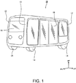
- FIG. 1 is an external view illustrating an autonomous vehicle 10 according to the present embodiment.
- the terms “front (FR)” and “rear” indicate front and rear in the longitudinal or front-rear direction of the vehicle, and the terms “left (LH)” and “right” indicate left and right when facing forward, and “up (UP)” and “down” indicate up and down in the vertical direction of the vehicle.
- the autonomous vehicle 10 is a substantially rectangular parallelepiped and has a shape symmetrical in the front-rear direction, and an appearance design thereof is symmetrical in the longitudinal direction.
- a pillar 12 extending in the vertical direction is provided at each of four corners in a plan view, and a wheel 14 is provided below each pillar 12.
- Most of front, rear, left, and right side walls of the autonomous vehicle 10 are semitransparent panels 16.
- Each panel 16 may be configured as a display panel, on which characters or the like can be displayed.
- the left side panel is constituted as a slidable door 18, so that an occupant can get on and off by sliding and opening the door 18.
- retractable ramp equipment configured to be taken out and in is stored below the door 18. The ramp equipment can be used for loading and unloading a wheelchair or the like.
- the autonomous vehicle 10 is a vehicle capable of performing autonomous driving. Specifically, the autonomous vehicle 10 is configured to perform driving in a plurality of driving modes including an automatic driving mode, a semi-automatic driving mode, and a manual driving mode.
- the automatic driving mode is a driving mode in which a computer (serving as a driving control unit (described below)) mounted on the autonomous vehicle 10 performs most of the driving control.
- the driving control is a concept including shift change control, vehicle speed control, and steering control.
- the vehicle speed control is also a concept including start control, stop control, and acceleration/deceleration control for the autonomous vehicle 10.
- the autonomous vehicle 10 is configured to be able to communicate with a management center that manages and controls a plurality of autonomous vehicles 10.
- the autonomous vehicle 10 travels along a predetermined route under the control of the management center.
- the computer performs the driving control according to driving instructions from the management center.
- the start control performed in a stop state requires an operation by an operator in the autonomous vehicle 10.
- the semi-automatic driving mode is a driving mode similar to the automatic driving mode in that the computer mounted on the autonomous vehicle 10 performs most of the driving control for the autonomous vehicle 10.
- the computer performs driving control based on detection results obtained by various sensors (for example, a camera or a light detection and ranging "lidar" device) provided on the autonomous vehicle 10, travels along a predetermined route.
- various sensors for example, a camera or a light detection and ranging "lidar" device
- the start control performed in a stop state requires an operation by an operator in the autonomous vehicle 10.
- the manual driving mode is a mode in which the autonomous vehicle 10 does not perform autonomous driving and an operator in the autonomous vehicle 10 performs driving control for the autonomous vehicle 10.
- the autonomous vehicle 10 is a shared vehicle for riding by an unspecified large number of occupants.
- the autonomous vehicle 10 is used as a bus that carries passengers while traveling along a predetermined route in a specific site. Accordingly, the autonomous vehicle 10 is supposed to repeat stopping and starting relatively frequently. Further, the autonomous vehicle 10 is supposed to travel relatively slowly (e.g., at 30 km/h or less).
- the usage form of the autonomous vehicle 10 disclosed in the present description is appropriately changeable.
- the autonomous vehicle 10 may be used as a movable business space, or as a shop such as a retail shop that displays and sells various commodities, or as a restaurant that cooks and provides food and drink.
- the autonomous vehicle 10 may be used as an office for various types of office work, meeting with customers, and the like.
- the use scene of the autonomous vehicle 10 is not limited to business use.
- the autonomous vehicle 10 may be used as personal transportation means. Further, the traveling pattern or the traveling speed of the autonomous vehicle 10 may be changed appropriately.
- the autonomous vehicle 10 is an electric vehicle having, as a prime mover, a driving motor that receives power supply from batteries. Each battery is a secondary battery configured to be chargeable and dischargeable, and is periodically charged by an external power source.
- the autonomous vehicle 10 is not limited to the electric vehicle and may be another type of vehicle.
- the autonomous vehicle 10 may be a vehicle equipped with an engine (e.g., an internal combustion engine) serving as a prime mover, or may be a hybrid vehicle equipped with both an engine and a driving motor each serving as a prime mover.
- the autonomous vehicle 10 may be a hydrogen fueled vehicle that drives a driving motor with electric power generated by fuel cells
- FIGS. 2 and 3 are perspective diagrams illustrating the interior of a passenger compartment of the autonomous vehicle 10.
- the passenger compartment includes a central part configured as a floor 20 available for standing occupants or wheelchaired occupants. Further, occupant seats 22 are provided along sidewalls in the passenger compartment.
- the autonomous vehicle 10 includes an operator seat 24 provided for an operator who controls driving of the autonomous vehicle 10 and operates each device (such as an air conditioner or windshield wipers) provided in the autonomous vehicle 10.
- FIG. 2 illustrates a state where a seat body 24a of the operator seat 24 is reclined so that a seat surface 24b appears.
- the seat body 24a is configured to be flipped up.
- the operator seat 24 is provided on the left side in the passenger compartment and adjacent to the front side of the door 18, although the operator seat 24 may be provided on the right side in the passenger compartment.
- An armrest 26 extending in the front-rear direction to enable an operator sitting on the operator seat 24 to place his/her arm is provided on the front side of the operator seat 24.
- the armrest 26 is located on the front side of the operator seat 24, an occupant other than the operator can visually recognize the armrest 26, since the operator seat 24 is on the floor 20.
- the armrest 26 is disposed at the left end in the passenger compartment. If the operator seat 24 is provided on the right side in the passenger compartment, the armrest 26 is disposed at the right end in the passenger compartment.
- the armrest 26 is provided higher than the seat surface 24b of the operator seat 24 in a reclined state.
- a touch panel 28 standing upright from an upper surface of the armrest 26 is provided at a front end of the armrest 26 (see FIG. 3 ).
- the touch panel 28 faces the rear side (that is, the operator seat 24 side). Accordingly, the operator can manually operate the touch panel 28 while sitting on the operator seat 24 and placing his/her arm on the armrest 26.
- the touch panel 28 enables the operator to input a vehicle speed control instruction during the automatic driving mode and input a device control instruction to each device (blinkers, a horn, headlights, the air conditioner, the windshield wipers, and the like) provided in the autonomous vehicle 10.
- a display screen of the touch panel 28 will be described in detail below.
- a storage compartment 30 such as a console box, which can store a mechanical operation unit for inputting a driving control instruction to the autonomous vehicle 10, is provided in the armrest 26.
- the storage compartment 30 is covered with a lid 32. That is, the mechanical operation unit when stored in the storage compartment 30 is not exposed to the interior of the passenger compartment.
- the upper surface of the armrest 26 and the lid 32 are disposed on the same plane.
- the storage compartment 30 is provided in the armrest 26, the storage compartment 30 may be provided in a place other than the armrest 26. Even in such a case, it is desirable that the storage compartment 30 is provided in an inconspicuous place, for example, at one of front, rear, left, and right ends in the interior of the passenger compartment.
- the storage compartment 30, the lid 32, and the mechanical operation unit will be described in detail below.
- a mechanical emergency-stop operation unit 34 for inputting an (emergency) stop instruction to the autonomous vehicle 10 is provided on the upper surface of the armrest 26.
- the emergency-stop operation unit 34 is a button.
- the autonomous vehicle 10 is provided with the touch panel 28, the mechanical operation unit, and the emergency-stop operation unit 34, as only three operation devices for inputting vehicle speed control instructions to the autonomous vehicle 10. That is, the autonomous vehicle 10 is not provided with a foot-operated pedal for inputting a vehicle speed control instruction, such as an accelerator pedal or a brake pedal provided in conventional automotive vehicles or the like.
- a display device 36 that displays information relating to the autonomous vehicle 10 is provided at a front left corner in the passenger compartment (see FIG. 3 ).
- the information displayed on the display device 36 includes, for example, vehicle speed of the autonomous vehicle 10, ambient temperature, and the next stop.
- the display device 36 faces the rear side so that the touch panel 28 and the display device 36 are disposed side by side when seen by the operator sitting on the operator seat.
- the operator can visually recognize both the touch panel 28 and the display device 36.
- the display device 36 and the touch panel 28 may be positioned at the same height.
- the touch panel 28 and the display device 36 are disposed in such a manner that the upper edge of the display device 36 and the upper edge of the touch panel 28 are at the same height, the lower edge of the display device 36 and the lower edge of the touch panel 28 are at the same height, or the altitudinal center of the display device 36 and the altitudinal center of the touch panel 28 are at the same height.
- FIGS. 4 and 5 illustrate exemplary screens to be displayed on the touch panel 28.
- FIG. 4 illustrates an exemplary screen displayed when the autonomous vehicle 10 is in the automatic driving mode and is stopped.
- FIG. 5 is an exemplary screen displayed when the autonomous vehicle 10 is in the automatic driving mode and is traveling.
- a GO button 40 serving as a vehicle speed control button for inputting a vehicle speed control instruction to the autonomous vehicle 10 is displayed on the touch panel 28.
- the GO button 40 is a button for inputting a start instruction to the autonomous vehicle 10.
- the autonomous vehicle 10 starts traveling (in the automatic driving mode, in this case).
- a SLOWDOWN button 42 serving as a vehicle speed control button is displayed on the touch panel 28, instead of the GO button 40.
- the SLOWDOWN button 42 is a button for inputting a deceleration control instruction to the autonomous vehicle 10.
- the SLOWDOWN button 42 When the SLOWDOWN button 42 is operated, the autonomous vehicle 10 decelerates.
- the SLOWDOWN button 42 may be repetitively operated to cause the autonomous vehicle 10 to stop as intended.
- the vehicle speed control that the operator can input is only the deceleration control instruction.
- a button for inputting an acceleration control instruction or a button for inputting a stop instruction may be displayed so that the operator can input the acceleration control instruction or the stop instruction.
- the autonomous vehicle 10 can automatically decelerate or stop according to an instruction from the management center.
- the GO button 40 is displayed again, instead of the SLOWDOWN button 42, as illustrated in FIG. 4 .
- the vehicle speed control buttons are not limited to the ones operable by the operator to directly input vehicle speed control instructions to the autonomous vehicle 10. That is, in addition to the GO button 40 and the SLOWDOWN button 42 for directly controlling the vehicle speed described in the present embodiment, the vehicle speed control buttons may include buttons for performing other controls and indirectly (consequently) controlling the vehicle speed.
- Buttons displayed on the touch panel 28 include, in addition to the vehicle speed control button, driving mode buttons 44 for inputting driving mode change instructions, shift buttons 46 for inputting shift change control instructions, a P brake button 48 for inputting a motor-driven parking brake activation/release instruction, and various device control buttons for inputting device control instructions to devices provided in the autonomous vehicle 10.
- blinker buttons 50 for controlling blinkers a hazard button 52 for activating a hazard warning system, a horn button 54 for operating the horn, light buttons 56 for controlling headlights and taillights, an air conditioner tab 58 for controlling the air conditioner, and a windshield wiper tab 60 for controlling the windshield wipers are displayed as the device control buttons.
- buttons for controlling the air conditioner are displayed.
- the windshield wiper tab 60 is touched, various buttons for controlling the windshield wipers are displayed.
- the driving mode buttons 44 are operable only when the autonomous vehicle 10 is stopped. Further, in the present embodiment, the shift buttons 46 are not operable in the automatic driving mode, because shift change by an operator's operation is restricted.
- other information displayed on the touch panel 28 includes remaining battery level of the autonomous vehicle 10, opened/closed state of the door 18, state of the ramp equipment, and detection states of various sensors provided in the autonomous vehicle 10.
- FIG. 6 illustrates a mechanical operation unit 70 pulled out of the storage compartment 30.
- the mechanical operation unit 70 is not the foot-operated pedal such as the accelerator pedal or the brake pedal provided in conventional automotive vehicles, and is provided higher than the seat surface of the operator seat 24 to enable hand operation by the operator.
- the mechanical operation unit 70 has a mechanical mechanism for inputting driving control instructions to the autonomous vehicle 10.
- the mechanical operation unit 70 has a stick shape, although the shape of the mechanical operation unit 70 is not limited to this example.
- the mechanical operation unit 70 may be a spherical lever.
- the mechanical operation unit 70 keeps an upright posture when stored in the storage compartment 30 so as to be raised in the vertical direction.
- Storing the mechanical operation unit 70 in the storage compartment 30 can prevent erroneous operation of the mechanical operation unit 70 by the operator or prevent operation of the mechanical operation unit 70 by another occupant.
- the lid 32 may be configured to be locked so that occupants other than the operator cannot open the lid 32. Further, an unlocking mechanism for releasing the lock when the lid 32 is slid (for example, slid in the horizontal direction) may be employed. The space in the vehicle can be effectively used when the mechanical operation unit 70 is stored in the storage compartment 30.
- the mechanical operation unit 70 When the operator opens the lid 32 and pulls out the mechanical operation unit 70 upward, the mechanical operation unit 70 becomes operable as illustrated in FIG. 6 .
- a switch may be provided in the storage compartment 30, so that the mechanical operation unit 70 automatically moves upward from the storage compartment 30 when the switch is operated.
- the mechanical operation unit 70 In the operable state, the mechanical operation unit 70 is in a state where it stands upright from the upper surface of the armrest 26. As described above, since the armrest 26 is provided higher than the seat surface 24b of the operator seat 24 in the reclined state, it is obvious that the mechanical operation unit 70 is positioned higher than the seat surface 24b in the reclined state.
- the mechanical operation unit 70 is mainly pulled out of the storage compartment 30 when the driving mode of the autonomous vehicle 10 is the manual driving mode.
- the driving mode of the autonomous vehicle 10 is the automatic driving mode or the semi-automatic driving mode
- the mechanical operation unit 70 is configured to include a grip part 70a, and a switch pedestal part 70b located above the grip part 70a.
- the operator while gripping the grip part 70a, can perform a lever operation for the mechanical operation unit 70. That is, the mechanical operation unit 70 is configured to be tiltable in the front, rear, left, and right directions with a lower edge thereof as a fulcrum.
- an acceleration control instruction can be input to the autonomous vehicle 10.
- a deceleration control instruction can be input to the autonomous vehicle 10.
- a left-turn control instruction can be input to the autonomous vehicle 10.
- a right-turn control instruction can be input to the autonomous vehicle 10.
- mechanical device control switches for inputting device control instructions to the devices provided in the autonomous vehicle 10 are provided at an upper part of the mechanical operation unit 70.
- switches for controlling the notification to the outside of the vehicle are provided as the device control switches.
- blinker switches 72 for operating the blinkers and a horn switch 74 for activating the horn are provided on the switch pedestal part 70b.
- the mechanical operation unit 70 can be used not only when instructing the acceleration/deceleration control and the turning control but also when operating the blinkers and the horn.
- the device control switches on the mechanical operation unit 70 may include additional switches for controlling other devices. Providing the blinker switches 72 and the horn switch 74 on the switch pedestal part 70b located above the grip part 70a enables the operator to operate the blinker switches 72 and the horn switch 74 while gripping the grip part 70a.
- the touch panel 28 is disposed at the front end of the armrest 26 and the mechanical operation unit 70 stands upright on the armrest 26. That is, the touch panel 28 and the mechanical operation unit 70 are disposed adjacently. In the present embodiment, even when the driving control is performed using the mechanical operation unit 70, the touch panel 28 is usable to operate the devices provided in the autonomous vehicle 10. Accordingly, since the touch panel 28 and the mechanical operation unit 70 are adjacent to each other, the operator can suitably operate both the touch panel 28 and the mechanical operation unit 70.
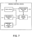
- FIG. 7 is a functional block diagram illustrating a driving control device 80 provided on the autonomous vehicle 10.
- the driving control device 80 includes the touch panel 28, the emergency-stop operation unit 34, and the mechanical operation unit 70, which are described above, and is configured to further include a driving mode selection unit 82 and a driving control unit 84.
- the driving mode selection unit 82 and the driving control unit 84 can be realized by cooperation of hardware such as a processor and software that causes the hardware to operate.
- the driving mode selection unit 82 selects, as the driving mode of the autonomous vehicle 10, any one of the automatic driving mode, the semi-automatic driving mode, and the manual driving mode. Specifically, the driving mode selection unit 82 selects the driving mode of the autonomous vehicle 10 based on the driving mode change instruction that has been input to the touch panel 28 by the operator. The driving mode selected by the driving mode selection unit 82 is notified to the driving control unit 84.
- the driving control unit 84 performs driving control for the autonomous vehicle 10 based on an instruction input from the touch panel 28, the emergency-stop operation unit 34, or the mechanical operation unit 70.
- the driving control unit 84 upon receiving the start instruction from the touch panel 28 when the GO button 40 (see FIG. 4 ) of the touch panel 28 is touched, releases the motor-driven parking brake and controls the prime mover to cause the autonomous vehicle 10 to start traveling. Further, upon receiving the deceleration control instruction from the touch panel 28 when the SLOWDOWN button 42 (see FIG. 5 ) of the touch panel 28 is touched, the driving control unit 84 controls the prime mover and the brake to cause the autonomous vehicle 10 to decelerate.
- the driving control unit 84 controls the prime mover to accelerate the autonomous vehicle 10 upon receiving the acceleration control instruction from the mechanical operation unit 70. Further, when the mechanical operation unit 70 is tilted rearward, the driving control unit 84 controls the prime mover or the brake to cause the autonomous vehicle 10 to decelerate upon receiving the deceleration control instruction from the mechanical operation unit 70. Further, when the mechanical operation unit 70 is tilted leftward, the driving control unit 84 controls the directions of the wheels 14 of the autonomous vehicle 10 to cause the autonomous vehicle 10 to turn left upon receiving the left-turn control instruction from the mechanical operation unit 70. When the mechanical operation unit 70 is tilted rightward, the driving control unit 84 controls the directions of the wheels 14 of the autonomous vehicle 10 to cause the autonomous vehicle 10 to turn right upon receiving the right-turn control instruction from the mechanical operation unit 70.
- the driving control unit 84 controls the prime mover and the brake to cause the autonomous vehicle 10 to stop immediately upon receiving the stop instruction from the emergency-stop operation unit 34.
- the driving control unit 84 performs driving control for the autonomous vehicle 10 based on driving instructions received from the management center. Further, in the case of operation in the semi-automatic driving mode, the driving control unit 84 performs driving control for the autonomous vehicle 10 based on detection results by various sensors of the autonomous vehicle 10.
- the driving control unit 84 executes the driving control including the vehicle speed control for the autonomous vehicle 10. Accordingly, the driving control unit 84 functions as a vehicle speed control unit, and the driving control device 80 functions as a vehicle speed control device.
- the driving control unit 84 can perform driving control for the autonomous vehicle 10 based on driving control instructions from the touch panel 28 and the mechanical operation unit 70.
- the driving control unit 84 prioritizes a vehicle speed control instruction input from the touch panel 28 over a vehicle speed control instruction input from the mechanical operation unit 70 and executes the vehicle speed control for the autonomous vehicle 10 based on the prioritized instruction.
- prioritizing the vehicle speed control instruction input from the touch panel 28 in the automatic driving mode or the semi-automatic driving mode invalidates the vehicle speed control instruction input from the mechanical operation unit 70, after the vehicle speed control instruction is input by the touch panel 28, until the driving control unit 84 completes the vehicle speed control.
- the driving control unit 84 ignores the acceleration control instruction from the mechanical operation unit 70 and causes the autonomous vehicle 10 to decelerate, until the driving control unit 84 completes the deceleration control, even when the mechanical operation unit 70 is tilted forward.
- the vehicle speed control instruction from the touch panel 28 may be prioritized by not receiving any vehicle speed control instruction from the mechanical operation unit 70.
- any vehicle speed control instruction from the mechanical operation unit 70 is invalidated, regardless of whether the operator is operating the touch panel 28.
- the driving control unit 84 performs driving control for the autonomous vehicle 10 based on driving instructions from the management center. However, the vehicle speed control instructions from the touch panel 28 and the mechanical operation unit 70 are prioritized over the vehicle speed control instructions from the management center. Further, in the case of operation in the semi-automatic driving mode, the driving control unit 84 performs driving control for the autonomous vehicle 10 based on detection results by various sensors of the autonomous vehicle 10. However, the vehicle speed control instructions from the touch panel 28 and the mechanical operation unit 70 are prioritized over the vehicle speed control instructions based on detection results of various sensors.
- the vehicle speed control instructions input from the touch panel 28 are prioritized over the vehicle speed control instructions input from the mechanical operation unit 70 in the automatic driving mode. Therefore, even when the mechanical operation unit 70 is unwantedly operated by the operator or another occupant while the operator is performing vehicle speed control using the touch panel 28, performance of any vehicle speed control not intended by the operator can be suppressed.
- the driving control unit 84 may prioritize the vehicle speed control instructions input from the mechanical operation unit 70 over the vehicle speed control instructions input from the touch panel 28 and execute the vehicle speed control for the autonomous vehicle 10 based on the prioritized instructions. For example, in the manual driving mode, after the mechanical operation unit 70 inputs a vehicle speed control instruction, until the driving control unit 84 completes the vehicle speed control, any vehicle speed control instruction input from the touch panel 28 may be invalidated.
- the driving control unit 84 prioritizes the stop instruction input from the emergency-stop operation unit 34 over the vehicle speed control instructions input from the touch panel 28 and the mechanical operation unit 70 and causes the autonomous vehicle 10 to stop immediately.
- the stop instruction input from the emergency-stop operation unit 34 is prioritized over the vehicle speed control instructions from the management center and the vehicle speed control instruction based on detection results by various sensors of the autonomous vehicle 10. That is, regardless of the driving mode of the autonomous vehicle 10, and regardless of how the touch panel 28 or the mechanical operation unit 70 is operated, the autonomous vehicle 10 immediately stops when the emergency-stop operation unit 34 is operated. Thus, the operator can stop the autonomous vehicle 10 at any time in an emergency.
- separately providing the emergency-stop operation unit 34 and the mechanical operation unit 70 can prevent erroneous operation of the emergency-stop operation unit 34 by the operator in the manual driving mode. Further, when the emergency-stop operation unit 34 is provided between the touch panel 28 and the mechanical operation unit 70 on the armrest 26, any occupant can visually recognize the emergency-stop operation unit 34 in the automatic driving mode, because the mechanical operation unit 70 can be stored in the storage compartment 30. That is, anyone can operate the emergency-stop operation unit 34 in case of emergency.
- the autonomous vehicle operation device according to the present disclosure is not limited to the above-mentioned embodiments and can be changed or modified in various ways without departing from the scope thereof.
Landscapes
- Engineering & Computer Science (AREA)
- Mechanical Engineering (AREA)
- Transportation (AREA)
- Chemical & Material Sciences (AREA)
- Combustion & Propulsion (AREA)
- Human Computer Interaction (AREA)
- Automation & Control Theory (AREA)
- Physics & Mathematics (AREA)
- General Engineering & Computer Science (AREA)
- Theoretical Computer Science (AREA)
- General Physics & Mathematics (AREA)
- Acoustics & Sound (AREA)
- Control Of Driving Devices And Active Controlling Of Vehicle (AREA)
- Control Of Position, Course, Altitude, Or Attitude Of Moving Bodies (AREA)
- Auxiliary Drives, Propulsion Controls, And Safety Devices (AREA)
- Mechanical Control Devices (AREA)
- Steering Controls (AREA)
Abstract
Description
- This application claims priority to Japanese Patent Application No.
2019-121404 filed on June 28, 2019 - The present description discloses an autonomous vehicle operation device.
- Autonomous vehicles capable of performing automatic driving are conventionally known. Automatic driving means that a computer executes at least a part of various driving controls including vehicle speed control and steering control.
- It is conventionally known that, even in an autonomous vehicle capable of performing autonomous driving, an operator in the autonomous vehicle may want to perform driving control, and there has been a case of providing a mechanical operation unit in the autonomous vehicle for enabling the operator to perform driving control for the autonomous vehicle. The mechanical operation unit is not a foot-operated pedal such as an accelerator pedal or a brake pedal provided in conventional automotive vehicles, and is provided higher than a seat surface of an operator's seat to enable hand operation by the operator.
- For example,
JP 2018-136714 A - Incidentally, there is a case where an autonomous vehicle is used as a shared vehicle for riding by an unspecified large number of occupants. In such a case, if the mechanical operation unit is operated by an occupant other than an operator, a driving instruction not intended by the operator may be input and the driving of the autonomous vehicle may be disturbed.
- An autonomous vehicle operation device disclosed in the present description is applicable to a shared autonomous vehicle including a mechanical operation unit that enables an operator to perform driving control and intends to suppress operation of the mechanical operation unit by an occupant other than the operator.
- The autonomous vehicle operation device disclosed in the present description is an operation device for a shared autonomous vehicle that is capable of performing automatic driving and is for riding by an unspecified large number of occupants, including a mechanical operation unit configured to perform driving control for the autonomous vehicle, wherein the mechanical operation unit can be stored in a storage compartment covered with a lid.
- According to the above-mentioned configuration, by storing the mechanical operation unit in the storage compartment covered with the lid, operation of the mechanical operation unit by an occupant other than an operator can be suppressed.
- It is desirable that the storage compartment is provided in an armrest disposed at either a left end or a right end in a passenger compartment of the autonomous vehicle.
- It is desirable that a touch panel is provided at a front end of the armrest, and a vehicle speed control button for inputting a vehicle speed control instruction to the autonomous vehicle is displayed on the touch panel.
- It is desirable that the mechanical operation unit includes a blinker switch for operating a blinker and a horn switch for activating a horn.
- It is desirable that the mechanical operation unit includes a grip part and a switch pedestal part located above the grip part, and the blinker switch and the horn switch are provided on the switch pedestal part.
- It is desirable that an emergency-stop operation unit is disposed between the touch panel and the mechanical operation unit on an upper surface of the armrest.
- It is desirable that the autonomous vehicle can perform driving in an automatic driving mode for performing automatic driving and in a manual driving mode in which an operator in the autonomous vehicle performs driving control, and driving control of the autonomous vehicle by the mechanical operation unit is feasible in each of the automatic driving mode and the manual driving mode.
- According to the autonomous vehicle operation device disclosed in the present description, in a shared autonomous vehicle including a mechanical operation unit that enables an operator to perform driving control, operation of the mechanical operation unit by an occupant other than the operator can be suppressed.
- Embodiment(s) of the present disclosure will be described based on the following figures, wherein:
-
FIG. 1 is an external view illustrating an autonomous vehicle according to the present embodiment; -
FIG. 2 is a first perspective diagram illustrating the interior of a passenger compartment of the autonomous vehicle according to the present embodiment; -
FIG. 3 is a second perspective diagram illustrating the interior of the passenger compartment of the autonomous vehicle according to the present embodiment; -
FIG. 4 is a diagram illustrating an exemplary screen of a touch panel to be displayed when the vehicle is stopped; -
FIG. 5 is a diagram illustrating an exemplary screen of the touch panel to be displayed at the time of automatic traveling; -
FIG. 6 is a perspective diagram illustrating a mechanical operation unit; and -
FIG. 7 is a functional block diagram illustrating a driving control device according to the present embodiment. -
FIG. 1 is an external view illustrating anautonomous vehicle 10 according to the present embodiment. In each drawing of the present description, the terms "front (FR)" and "rear" indicate front and rear in the longitudinal or front-rear direction of the vehicle, and the terms "left (LH)" and "right" indicate left and right when facing forward, and "up (UP)" and "down" indicate up and down in the vertical direction of the vehicle. - The
autonomous vehicle 10 is a substantially rectangular parallelepiped and has a shape symmetrical in the front-rear direction, and an appearance design thereof is symmetrical in the longitudinal direction. Apillar 12 extending in the vertical direction is provided at each of four corners in a plan view, and awheel 14 is provided below eachpillar 12. Most of front, rear, left, and right side walls of theautonomous vehicle 10 aresemitransparent panels 16. Eachpanel 16 may be configured as a display panel, on which characters or the like can be displayed. - Apart of the left side panel is constituted as a
slidable door 18, so that an occupant can get on and off by sliding and opening thedoor 18. Although not illustrated inFIG. 1 , retractable ramp equipment configured to be taken out and in is stored below thedoor 18. The ramp equipment can be used for loading and unloading a wheelchair or the like. - Further, the
autonomous vehicle 10 is a vehicle capable of performing autonomous driving. Specifically, theautonomous vehicle 10 is configured to perform driving in a plurality of driving modes including an automatic driving mode, a semi-automatic driving mode, and a manual driving mode. - The automatic driving mode is a driving mode in which a computer (serving as a driving control unit (described below)) mounted on the
autonomous vehicle 10 performs most of the driving control. In the present description, the driving control is a concept including shift change control, vehicle speed control, and steering control. Further, the vehicle speed control is also a concept including start control, stop control, and acceleration/deceleration control for theautonomous vehicle 10. Theautonomous vehicle 10 is configured to be able to communicate with a management center that manages and controls a plurality ofautonomous vehicles 10. In the automatic driving mode, theautonomous vehicle 10 travels along a predetermined route under the control of the management center. In the automatic driving mode, the computer performs the driving control according to driving instructions from the management center. However, the start control performed in a stop state requires an operation by an operator in theautonomous vehicle 10. - The semi-automatic driving mode is a driving mode similar to the automatic driving mode in that the computer mounted on the
autonomous vehicle 10 performs most of the driving control for theautonomous vehicle 10. In the semi-automatic driving mode, without depending on instructions from the management center, the computer performs driving control based on detection results obtained by various sensors (for example, a camera or a light detection and ranging "lidar" device) provided on theautonomous vehicle 10, travels along a predetermined route. However, even in the semi-automatic driving mode, the start control performed in a stop state requires an operation by an operator in theautonomous vehicle 10. - The manual driving mode is a mode in which the
autonomous vehicle 10 does not perform autonomous driving and an operator in theautonomous vehicle 10 performs driving control for theautonomous vehicle 10. - The
autonomous vehicle 10 is a shared vehicle for riding by an unspecified large number of occupants. In the present embodiment, theautonomous vehicle 10 is used as a bus that carries passengers while traveling along a predetermined route in a specific site. Accordingly, theautonomous vehicle 10 is supposed to repeat stopping and starting relatively frequently. Further, theautonomous vehicle 10 is supposed to travel relatively slowly (e.g., at 30 km/h or less). - However, the usage form of the
autonomous vehicle 10 disclosed in the present description is appropriately changeable. For example, theautonomous vehicle 10 may be used as a movable business space, or as a shop such as a retail shop that displays and sells various commodities, or as a restaurant that cooks and provides food and drink. Further, as another form, theautonomous vehicle 10 may be used as an office for various types of office work, meeting with customers, and the like. Further, the use scene of theautonomous vehicle 10 is not limited to business use. For example, theautonomous vehicle 10 may be used as personal transportation means. Further, the traveling pattern or the traveling speed of theautonomous vehicle 10 may be changed appropriately. - The
autonomous vehicle 10 is an electric vehicle having, as a prime mover, a driving motor that receives power supply from batteries. Each battery is a secondary battery configured to be chargeable and dischargeable, and is periodically charged by an external power source. Theautonomous vehicle 10 is not limited to the electric vehicle and may be another type of vehicle. For example, theautonomous vehicle 10 may be a vehicle equipped with an engine (e.g., an internal combustion engine) serving as a prime mover, or may be a hybrid vehicle equipped with both an engine and a driving motor each serving as a prime mover. Further, theautonomous vehicle 10 may be a hydrogen fueled vehicle that drives a driving motor with electric power generated by fuel cells -
FIGS. 2 and3 are perspective diagrams illustrating the interior of a passenger compartment of theautonomous vehicle 10. As mentioned above, since theautonomous vehicle 10 is used as a bus, the passenger compartment includes a central part configured as afloor 20 available for standing occupants or wheelchaired occupants. Further, occupant seats 22 are provided along sidewalls in the passenger compartment. - The
autonomous vehicle 10 includes anoperator seat 24 provided for an operator who controls driving of theautonomous vehicle 10 and operates each device (such as an air conditioner or windshield wipers) provided in theautonomous vehicle 10.FIG. 2 illustrates a state where aseat body 24a of theoperator seat 24 is reclined so that aseat surface 24b appears. Theseat body 24a is configured to be flipped up. In the present embodiment, theoperator seat 24 is provided on the left side in the passenger compartment and adjacent to the front side of thedoor 18, although theoperator seat 24 may be provided on the right side in the passenger compartment. - An armrest 26 extending in the front-rear direction to enable an operator sitting on the
operator seat 24 to place his/her arm is provided on the front side of theoperator seat 24. Although thearmrest 26 is located on the front side of theoperator seat 24, an occupant other than the operator can visually recognize thearmrest 26, since theoperator seat 24 is on thefloor 20. As mentioned above, in the present embodiment, since theoperator seat 24 is provided on the left side in the passenger compartment, thearmrest 26 is disposed at the left end in the passenger compartment. If theoperator seat 24 is provided on the right side in the passenger compartment, thearmrest 26 is disposed at the right end in the passenger compartment. Thearmrest 26 is provided higher than theseat surface 24b of theoperator seat 24 in a reclined state. - A
touch panel 28 standing upright from an upper surface of thearmrest 26 is provided at a front end of the armrest 26 (seeFIG. 3 ). Thetouch panel 28 faces the rear side (that is, theoperator seat 24 side). Accordingly, the operator can manually operate thetouch panel 28 while sitting on theoperator seat 24 and placing his/her arm on thearmrest 26. Thetouch panel 28 enables the operator to input a vehicle speed control instruction during the automatic driving mode and input a device control instruction to each device (blinkers, a horn, headlights, the air conditioner, the windshield wipers, and the like) provided in theautonomous vehicle 10. A display screen of thetouch panel 28 will be described in detail below. - Further, a
storage compartment 30 such as a console box, which can store a mechanical operation unit for inputting a driving control instruction to theautonomous vehicle 10, is provided in thearmrest 26. Thestorage compartment 30 is covered with alid 32. That is, the mechanical operation unit when stored in thestorage compartment 30 is not exposed to the interior of the passenger compartment. In the present embodiment, the upper surface of thearmrest 26 and thelid 32 are disposed on the same plane. Although in the present embodiment thestorage compartment 30 is provided in thearmrest 26, thestorage compartment 30 may be provided in a place other than thearmrest 26. Even in such a case, it is desirable that thestorage compartment 30 is provided in an inconspicuous place, for example, at one of front, rear, left, and right ends in the interior of the passenger compartment. Thestorage compartment 30, thelid 32, and the mechanical operation unit will be described in detail below. - Further, a mechanical emergency-
stop operation unit 34 for inputting an (emergency) stop instruction to theautonomous vehicle 10 is provided on the upper surface of thearmrest 26. In the present embodiment, the emergency-stop operation unit 34 is a button. - The
autonomous vehicle 10 is provided with thetouch panel 28, the mechanical operation unit, and the emergency-stop operation unit 34, as only three operation devices for inputting vehicle speed control instructions to theautonomous vehicle 10. That is, theautonomous vehicle 10 is not provided with a foot-operated pedal for inputting a vehicle speed control instruction, such as an accelerator pedal or a brake pedal provided in conventional automotive vehicles or the like. - A
display device 36 that displays information relating to theautonomous vehicle 10 is provided at a front left corner in the passenger compartment (seeFIG. 3 ). The information displayed on thedisplay device 36 includes, for example, vehicle speed of theautonomous vehicle 10, ambient temperature, and the next stop. Like thetouch panel 28, thedisplay device 36 faces the rear side so that thetouch panel 28 and thedisplay device 36 are disposed side by side when seen by the operator sitting on the operator seat. Thus, suitably, the operator can visually recognize both thetouch panel 28 and thedisplay device 36. Thedisplay device 36 and thetouch panel 28 may be positioned at the same height. Specifically, thetouch panel 28 and thedisplay device 36 are disposed in such a manner that the upper edge of thedisplay device 36 and the upper edge of thetouch panel 28 are at the same height, the lower edge of thedisplay device 36 and the lower edge of thetouch panel 28 are at the same height, or the altitudinal center of thedisplay device 36 and the altitudinal center of thetouch panel 28 are at the same height. -
FIGS. 4 and5 illustrate exemplary screens to be displayed on thetouch panel 28.FIG. 4 illustrates an exemplary screen displayed when theautonomous vehicle 10 is in the automatic driving mode and is stopped.FIG. 5 is an exemplary screen displayed when theautonomous vehicle 10 is in the automatic driving mode and is traveling. - First, with reference to
FIG. 4 , when theautonomous vehicle 10 is in the automatic driving mode and is stopped, aGO button 40 serving as a vehicle speed control button for inputting a vehicle speed control instruction to theautonomous vehicle 10 is displayed on thetouch panel 28. TheGO button 40 is a button for inputting a start instruction to theautonomous vehicle 10. When theGO button 40 is operated, theautonomous vehicle 10 starts traveling (in the automatic driving mode, in this case). - Next, with reference to
FIG. 5 , when theautonomous vehicle 10 is in the automatic driving mode and is traveling, aSLOWDOWN button 42 serving as a vehicle speed control button is displayed on thetouch panel 28, instead of theGO button 40. TheSLOWDOWN button 42 is a button for inputting a deceleration control instruction to theautonomous vehicle 10. When theSLOWDOWN button 42 is operated, theautonomous vehicle 10 decelerates. TheSLOWDOWN button 42 may be repetitively operated to cause theautonomous vehicle 10 to stop as intended. - In the present embodiment, when the vehicle is traveling in the automatic driving mode, the vehicle speed control that the operator can input is only the deceleration control instruction. However, in addition to the
SLOWDOWN button 42, a button for inputting an acceleration control instruction or a button for inputting a stop instruction may be displayed so that the operator can input the acceleration control instruction or the stop instruction. Needless to say, in the automatic driving mode, theautonomous vehicle 10 can automatically decelerate or stop according to an instruction from the management center. When theautonomous vehicle 10 is stopped, theGO button 40 is displayed again, instead of theSLOWDOWN button 42, as illustrated inFIG. 4 . - The vehicle speed control buttons are not limited to the ones operable by the operator to directly input vehicle speed control instructions to the
autonomous vehicle 10. That is, in addition to theGO button 40 and theSLOWDOWN button 42 for directly controlling the vehicle speed described in the present embodiment, the vehicle speed control buttons may include buttons for performing other controls and indirectly (consequently) controlling the vehicle speed. - Buttons displayed on the
touch panel 28 include, in addition to the vehicle speed control button, drivingmode buttons 44 for inputting driving mode change instructions,shift buttons 46 for inputting shift change control instructions, aP brake button 48 for inputting a motor-driven parking brake activation/release instruction, and various device control buttons for inputting device control instructions to devices provided in theautonomous vehicle 10. According to the examples illustrated inFIGS. 4 and5 ,blinker buttons 50 for controlling blinkers, ahazard button 52 for activating a hazard warning system, ahorn button 54 for operating the horn,light buttons 56 for controlling headlights and taillights, anair conditioner tab 58 for controlling the air conditioner, and awindshield wiper tab 60 for controlling the windshield wipers are displayed as the device control buttons. When theair conditioner tab 58 is touched, various buttons for controlling the air conditioner are displayed. When thewindshield wiper tab 60 is touched, various buttons for controlling the windshield wipers are displayed. The drivingmode buttons 44 are operable only when theautonomous vehicle 10 is stopped. Further, in the present embodiment, theshift buttons 46 are not operable in the automatic driving mode, because shift change by an operator's operation is restricted. - Further, other information displayed on the
touch panel 28 includes remaining battery level of theautonomous vehicle 10, opened/closed state of thedoor 18, state of the ramp equipment, and detection states of various sensors provided in theautonomous vehicle 10. -
FIG. 6 illustrates amechanical operation unit 70 pulled out of thestorage compartment 30. As mentioned above, themechanical operation unit 70 is not the foot-operated pedal such as the accelerator pedal or the brake pedal provided in conventional automotive vehicles, and is provided higher than the seat surface of theoperator seat 24 to enable hand operation by the operator. In particular, themechanical operation unit 70 has a mechanical mechanism for inputting driving control instructions to theautonomous vehicle 10. In the present embodiment, themechanical operation unit 70 has a stick shape, although the shape of themechanical operation unit 70 is not limited to this example. For example, themechanical operation unit 70 may be a spherical lever. Themechanical operation unit 70 keeps an upright posture when stored in thestorage compartment 30 so as to be raised in the vertical direction. Storing themechanical operation unit 70 in thestorage compartment 30 can prevent erroneous operation of themechanical operation unit 70 by the operator or prevent operation of themechanical operation unit 70 by another occupant. Thelid 32 may be configured to be locked so that occupants other than the operator cannot open thelid 32. Further, an unlocking mechanism for releasing the lock when thelid 32 is slid (for example, slid in the horizontal direction) may be employed. The space in the vehicle can be effectively used when themechanical operation unit 70 is stored in thestorage compartment 30. - When the operator opens the
lid 32 and pulls out themechanical operation unit 70 upward, themechanical operation unit 70 becomes operable as illustrated inFIG. 6 . Alternatively, a switch may be provided in thestorage compartment 30, so that themechanical operation unit 70 automatically moves upward from thestorage compartment 30 when the switch is operated. In the operable state, themechanical operation unit 70 is in a state where it stands upright from the upper surface of thearmrest 26. As described above, since thearmrest 26 is provided higher than theseat surface 24b of theoperator seat 24 in the reclined state, it is obvious that themechanical operation unit 70 is positioned higher than theseat surface 24b in the reclined state. - The
mechanical operation unit 70 is mainly pulled out of thestorage compartment 30 when the driving mode of theautonomous vehicle 10 is the manual driving mode. When the driving mode of theautonomous vehicle 10 is the automatic driving mode or the semi-automatic driving mode, it is desirable that themechanical operation unit 70 is stored in thestorage compartment 30 so as to prevent erroneous operation of themechanical operation unit 70. - The
mechanical operation unit 70 is configured to include agrip part 70a, and aswitch pedestal part 70b located above thegrip part 70a. The operator, while gripping thegrip part 70a, can perform a lever operation for themechanical operation unit 70. That is, themechanical operation unit 70 is configured to be tiltable in the front, rear, left, and right directions with a lower edge thereof as a fulcrum. When themechanical operation unit 70 is tilted forward, an acceleration control instruction can be input to theautonomous vehicle 10. When themechanical operation unit 70 is tilted rearward, a deceleration control instruction can be input to theautonomous vehicle 10. Further, when themechanical operation unit 70 is tilted leftward, a left-turn control instruction can be input to theautonomous vehicle 10. When themechanical operation unit 70 is tilted rightward, a right-turn control instruction can be input to theautonomous vehicle 10. - Further, mechanical device control switches for inputting device control instructions to the devices provided in the
autonomous vehicle 10 are provided at an upper part of themechanical operation unit 70. In the present embodiment, switches for controlling the notification to the outside of the vehicle are provided as the device control switches. Specifically, blinker switches 72 for operating the blinkers and ahorn switch 74 for activating the horn are provided on theswitch pedestal part 70b. As described above, themechanical operation unit 70 can be used not only when instructing the acceleration/deceleration control and the turning control but also when operating the blinkers and the horn. Needless to say, the device control switches on themechanical operation unit 70 may include additional switches for controlling other devices. Providing the blinker switches 72 and thehorn switch 74 on theswitch pedestal part 70b located above thegrip part 70a enables the operator to operate the blinker switches 72 and thehorn switch 74 while gripping thegrip part 70a. - In the present embodiment, the
touch panel 28 is disposed at the front end of thearmrest 26 and themechanical operation unit 70 stands upright on thearmrest 26. That is, thetouch panel 28 and themechanical operation unit 70 are disposed adjacently. In the present embodiment, even when the driving control is performed using themechanical operation unit 70, thetouch panel 28 is usable to operate the devices provided in theautonomous vehicle 10. Accordingly, since thetouch panel 28 and themechanical operation unit 70 are adjacent to each other, the operator can suitably operate both thetouch panel 28 and themechanical operation unit 70. -
FIG. 7 is a functional block diagram illustrating a drivingcontrol device 80 provided on theautonomous vehicle 10. The drivingcontrol device 80 includes thetouch panel 28, the emergency-stop operation unit 34, and themechanical operation unit 70, which are described above, and is configured to further include a drivingmode selection unit 82 and a drivingcontrol unit 84. The drivingmode selection unit 82 and the drivingcontrol unit 84 can be realized by cooperation of hardware such as a processor and software that causes the hardware to operate. - The driving
mode selection unit 82 selects, as the driving mode of theautonomous vehicle 10, any one of the automatic driving mode, the semi-automatic driving mode, and the manual driving mode. Specifically, the drivingmode selection unit 82 selects the driving mode of theautonomous vehicle 10 based on the driving mode change instruction that has been input to thetouch panel 28 by the operator. The driving mode selected by the drivingmode selection unit 82 is notified to the drivingcontrol unit 84. - The driving
control unit 84 performs driving control for theautonomous vehicle 10 based on an instruction input from thetouch panel 28, the emergency-stop operation unit 34, or themechanical operation unit 70. - Specifically, upon receiving the start instruction from the
touch panel 28 when the GO button 40 (seeFIG. 4 ) of thetouch panel 28 is touched, the drivingcontrol unit 84 releases the motor-driven parking brake and controls the prime mover to cause theautonomous vehicle 10 to start traveling. Further, upon receiving the deceleration control instruction from thetouch panel 28 when the SLOWDOWN button 42 (seeFIG. 5 ) of thetouch panel 28 is touched, the drivingcontrol unit 84 controls the prime mover and the brake to cause theautonomous vehicle 10 to decelerate. - When the
mechanical operation unit 70 is tilted forward, the drivingcontrol unit 84 controls the prime mover to accelerate theautonomous vehicle 10 upon receiving the acceleration control instruction from themechanical operation unit 70. Further, when themechanical operation unit 70 is tilted rearward, the drivingcontrol unit 84 controls the prime mover or the brake to cause theautonomous vehicle 10 to decelerate upon receiving the deceleration control instruction from themechanical operation unit 70. Further, when themechanical operation unit 70 is tilted leftward, the drivingcontrol unit 84 controls the directions of thewheels 14 of theautonomous vehicle 10 to cause theautonomous vehicle 10 to turn left upon receiving the left-turn control instruction from themechanical operation unit 70. When themechanical operation unit 70 is tilted rightward, the drivingcontrol unit 84 controls the directions of thewheels 14 of theautonomous vehicle 10 to cause theautonomous vehicle 10 to turn right upon receiving the right-turn control instruction from themechanical operation unit 70. - Further, when the emergency-
stop operation unit 34 is operated, the drivingcontrol unit 84 controls the prime mover and the brake to cause theautonomous vehicle 10 to stop immediately upon receiving the stop instruction from the emergency-stop operation unit 34. - In the case of operation in the automatic driving mode, the driving
control unit 84 performs driving control for theautonomous vehicle 10 based on driving instructions received from the management center. Further, in the case of operation in the semi-automatic driving mode, the drivingcontrol unit 84 performs driving control for theautonomous vehicle 10 based on detection results by various sensors of theautonomous vehicle 10. - As mentioned above, the driving
control unit 84 executes the driving control including the vehicle speed control for theautonomous vehicle 10. Accordingly, the drivingcontrol unit 84 functions as a vehicle speed control unit, and the drivingcontrol device 80 functions as a vehicle speed control device. - Irrespective of the driving mode of the
autonomous vehicle 10, the drivingcontrol unit 84 can perform driving control for theautonomous vehicle 10 based on driving control instructions from thetouch panel 28 and themechanical operation unit 70. However, when the driving mode of theautonomous vehicle 10 is either the automatic driving mode or the semi-automatic driving mode, the drivingcontrol unit 84 prioritizes a vehicle speed control instruction input from thetouch panel 28 over a vehicle speed control instruction input from themechanical operation unit 70 and executes the vehicle speed control for theautonomous vehicle 10 based on the prioritized instruction. - For example, prioritizing the vehicle speed control instruction input from the
touch panel 28 in the automatic driving mode or the semi-automatic driving mode invalidates the vehicle speed control instruction input from themechanical operation unit 70, after the vehicle speed control instruction is input by thetouch panel 28, until the drivingcontrol unit 84 completes the vehicle speed control. Specifically, when theSLOWDOWN button 42 of thetouch panel 28 is touched, the drivingcontrol unit 84 ignores the acceleration control instruction from themechanical operation unit 70 and causes theautonomous vehicle 10 to decelerate, until the drivingcontrol unit 84 completes the deceleration control, even when themechanical operation unit 70 is tilted forward. - Alternatively, in the case of operation in the automatic driving mode or the semi-automatic driving mode, the vehicle speed control instruction from the
touch panel 28 may be prioritized by not receiving any vehicle speed control instruction from themechanical operation unit 70. In this case, in the automatic driving mode or the semi-automatic driving mode, any vehicle speed control instruction from themechanical operation unit 70 is invalidated, regardless of whether the operator is operating thetouch panel 28. - In the case of operation in the automatic driving mode, the driving
control unit 84 performs driving control for theautonomous vehicle 10 based on driving instructions from the management center. However, the vehicle speed control instructions from thetouch panel 28 and themechanical operation unit 70 are prioritized over the vehicle speed control instructions from the management center. Further, in the case of operation in the semi-automatic driving mode, the drivingcontrol unit 84 performs driving control for theautonomous vehicle 10 based on detection results by various sensors of theautonomous vehicle 10. However, the vehicle speed control instructions from thetouch panel 28 and themechanical operation unit 70 are prioritized over the vehicle speed control instructions based on detection results of various sensors. - As described above, in the present embodiment, the vehicle speed control instructions input from the
touch panel 28 are prioritized over the vehicle speed control instructions input from themechanical operation unit 70 in the automatic driving mode. Therefore, even when themechanical operation unit 70 is unwantedly operated by the operator or another occupant while the operator is performing vehicle speed control using thetouch panel 28, performance of any vehicle speed control not intended by the operator can be suppressed. - When the driving mode of the
autonomous vehicle 10 is the manual driving mode, the drivingcontrol unit 84 may prioritize the vehicle speed control instructions input from themechanical operation unit 70 over the vehicle speed control instructions input from thetouch panel 28 and execute the vehicle speed control for theautonomous vehicle 10 based on the prioritized instructions. For example, in the manual driving mode, after themechanical operation unit 70 inputs a vehicle speed control instruction, until the drivingcontrol unit 84 completes the vehicle speed control, any vehicle speed control instruction input from thetouch panel 28 may be invalidated. - In addition, irrespective of the driving mode of the
autonomous vehicle 10, the drivingcontrol unit 84 prioritizes the stop instruction input from the emergency-stop operation unit 34 over the vehicle speed control instructions input from thetouch panel 28 and themechanical operation unit 70 and causes theautonomous vehicle 10 to stop immediately. Needless to say, the stop instruction input from the emergency-stop operation unit 34 is prioritized over the vehicle speed control instructions from the management center and the vehicle speed control instruction based on detection results by various sensors of theautonomous vehicle 10. That is, regardless of the driving mode of theautonomous vehicle 10, and regardless of how thetouch panel 28 or themechanical operation unit 70 is operated, theautonomous vehicle 10 immediately stops when the emergency-stop operation unit 34 is operated. Thus, the operator can stop theautonomous vehicle 10 at any time in an emergency. - Further, separately providing the emergency-
stop operation unit 34 and themechanical operation unit 70 can prevent erroneous operation of the emergency-stop operation unit 34 by the operator in the manual driving mode. Further, when the emergency-stop operation unit 34 is provided between thetouch panel 28 and themechanical operation unit 70 on thearmrest 26, any occupant can visually recognize the emergency-stop operation unit 34 in the automatic driving mode, because themechanical operation unit 70 can be stored in thestorage compartment 30. That is, anyone can operate the emergency-stop operation unit 34 in case of emergency. - Although the embodiments of the autonomous vehicle operation device according to the present disclosure have been described, the autonomous vehicle operation device according to the present disclosure is not limited to the above-mentioned embodiments and can be changed or modified in various ways without departing from the scope thereof.
Claims (7)
- An operation device for an autonomous vehicle (10) that is capable of performing automatic driving and is a shared vehicle for riding by an unspecified large number of occupants, comprising:a mechanical operation unit (70) configured to perform driving control for the autonomous vehicle (10),wherein the mechanical operation unit (70) can be stored in a storage compartment (30) covered with a lid (32).
- The autonomous vehicle operation device according to claim 1, wherein the storage compartment (30) is provided in an armrest (26) disposed at either a left end or a right end in a passenger compartment of the autonomous vehicle (10).
- The autonomous vehicle operation device according to claim 2, wherein
a touch panel (28) is provided at a front end of the armrest (26), and a vehicle speed control button (40, 42) for inputting a vehicle speed control instruction to the autonomous vehicle (10) is displayed on the touch panel. - The autonomous vehicle operation device according to any one of claims 1 to 3, wherein
the mechanical operation unit (70) includes a blinker switch (72) for operating a blinker and a horn switch (74) for activating a horn. - The autonomous vehicle operation device according to claim 4, wherein the mechanical operation unit (70) includes a grip part (70a) and a switch pedestal part (70b) located above the grip part (70a), and the blinker switch (72) and the horn switch (74) are provided on the switch pedestal part (70b).
- The autonomous vehicle operation device according to claim 3, further comprising: an emergency-stop operation unit (34) disposed between the touch panel (28) and the mechanical operation unit (70) on an upper surface of the armrest (26).
- The autonomous vehicle operation device according to claim 1 or 2, wherein the autonomous vehicle (10) can perform driving in an automatic driving mode for performing automatic driving and driving in a manual driving mode in which an operator on the autonomous vehicle performs driving control, and
driving control of the autonomous vehicle (10) by the mechanical operation unit (70) is feasible in each of the automatic driving mode and the manual driving mode.
Applications Claiming Priority (1)
| Application Number | Priority Date | Filing Date | Title |
|---|---|---|---|
| JP2019121404A JP7381230B2 (en) | 2019-06-28 | 2019-06-28 | Autonomous vehicle operating device |
Publications (2)
| Publication Number | Publication Date |
|---|---|
| EP3760468A1 true EP3760468A1 (en) | 2021-01-06 |
| EP3760468B1 EP3760468B1 (en) | 2022-03-23 |
Family
ID=71092454
Family Applications (1)
| Application Number | Title | Priority Date | Filing Date |
|---|---|---|---|
| EP20179562.2A Active EP3760468B1 (en) | 2019-06-28 | 2020-06-11 | Autonomous vehicle operation device |
Country Status (4)
| Country | Link |
|---|---|
| US (1) | US11731510B2 (en) |
| EP (1) | EP3760468B1 (en) |
| JP (1) | JP7381230B2 (en) |
| CN (1) | CN112140886A (en) |
Families Citing this family (5)
| Publication number | Priority date | Publication date | Assignee | Title |
|---|---|---|---|---|
| US10414344B1 (en) * | 2016-09-01 | 2019-09-17 | Apple Inc. | Securable storage compartments |
| JP7200853B2 (en) | 2019-06-28 | 2023-01-10 | トヨタ自動車株式会社 | Vehicle speed controller for self-driving vehicles |
| JP7439745B2 (en) * | 2020-12-18 | 2024-02-28 | トヨタ自動車株式会社 | self-driving vehicle |
| CN114809830B (en) * | 2022-05-05 | 2023-07-14 | 阿波罗智能技术(北京)有限公司 | Control method, device, electronic device and medium for a door of an automatic driving vehicle |
| KR102705944B1 (en) * | 2022-12-22 | 2024-09-13 | 한국자동차연구원 | Apparatus for manual operation of autonomous driving vehicle |
Citations (5)
| Publication number | Priority date | Publication date | Assignee | Title |
|---|---|---|---|---|
| WO2007034567A1 (en) * | 2005-09-20 | 2007-03-29 | Yoshiaki Takida | Drive-by-wire steering system of automobile vehicle |
| US20140188322A1 (en) * | 2012-12-27 | 2014-07-03 | Hyundai Motor Company | Driving mode changing method and apparatus of autonomous navigation vehicle |
| US20160264021A1 (en) * | 2010-01-04 | 2016-09-15 | Carla Gillett | Autonomous Vehicle Seating System |
| JP2018136714A (en) | 2017-02-21 | 2018-08-30 | トヨタ自動車株式会社 | Driving assistance device |
| US20190118852A1 (en) * | 2017-10-25 | 2019-04-25 | Honda Motor Co., Ltd. | Vehicle operation system, vehicle operation method, and storage medium |
Family Cites Families (35)
| Publication number | Priority date | Publication date | Assignee | Title |
|---|---|---|---|---|
| JPH01120560U (en) * | 1988-02-10 | 1989-08-15 | ||
| JP3052558B2 (en) | 1992-04-10 | 2000-06-12 | 三菱自動車工業株式会社 | Acceleration setting method |
| JP2894079B2 (en) | 1992-04-10 | 1999-05-24 | 三菱自動車工業株式会社 | Automatic acceleration / deceleration control device |
| JPH0682657U (en) | 1992-08-05 | 1994-11-25 | 新明和工業株式会社 | Driving simulator device |
| TW200701974A (en) | 2005-06-20 | 2007-01-16 | Family Co Ltd | Chair type massaging machine, massaging machine, operation device of chair type massaging machine, remote controller for chair type massaging machine |
| US9272724B2 (en) * | 2009-09-08 | 2016-03-01 | Golomb Mercantile Company Llc | Integrated vehicle control system and apparatus |
| DE102012002306A1 (en) * | 2012-02-06 | 2013-08-08 | Audi Ag | Motor vehicle with a driver assistance device and method for operating a motor vehicle |
| US9436182B2 (en) * | 2014-05-23 | 2016-09-06 | Google Inc. | Autonomous vehicles |
| JP2016004541A (en) * | 2014-06-19 | 2016-01-12 | 本田技研工業株式会社 | Vehicle operation input device |
| US10392007B1 (en) | 2015-03-26 | 2019-08-27 | Hydro-Gear Limited Partnership | Stability control system |
| FR3039314B1 (en) * | 2015-07-22 | 2017-07-21 | Crouzet Automatismes | SEALED HANDLE FOR CONTROLLING A MACHINE, SEALING ELEMENT FOR THIS HANDLE AND CONTROL PANEL COMPRISING THIS HANDLE |
| CN108778885B (en) | 2016-03-15 | 2021-09-10 | 本田技研工业株式会社 | Vehicle control system, vehicle control method, and storage medium |
| JP6298092B2 (en) * | 2016-03-18 | 2018-03-20 | 株式会社Subaru | Vehicle stop device |
| JP6368959B2 (en) | 2016-05-19 | 2018-08-08 | 本田技研工業株式会社 | Vehicle control system, vehicle control method, and vehicle control program |
| US10589679B1 (en) * | 2016-10-28 | 2020-03-17 | Zoox, Inc. | Providing visual references to prevent motion sickness in vehicles |
| JP6399129B2 (en) | 2017-03-08 | 2018-10-03 | オムロン株式会社 | Passenger support apparatus, method and program |
| JP6663382B2 (en) | 2017-03-24 | 2020-03-11 | ヤンマー株式会社 | Work vehicle |
| JP6916647B2 (en) | 2017-03-31 | 2021-08-11 | 本田技研工業株式会社 | Vehicle control systems, vehicle control methods, and vehicle control programs |
| JP6920112B2 (en) * | 2017-06-15 | 2021-08-18 | 株式会社デンソーテン | Driving support device and driving support method |
| US10843722B2 (en) * | 2017-06-16 | 2020-11-24 | Uatc, Llc | Systems and methods for controlling an input device of an autonomous vehicle |
| US11829903B2 (en) | 2017-08-01 | 2023-11-28 | Nissan Motor Co., Ltd. | Information providing method and information providing device |
| FR3070916B1 (en) * | 2017-09-08 | 2019-09-13 | Faurecia Interieur Industrie | ARMREST MODULE WITH MAN-MACHINE INTERFACE FOR VEHICLE SEAT |
| DE102017216178A1 (en) | 2017-09-13 | 2019-03-14 | Zf Friedrichshafen Ag | Method and movement device for moving at least part of a manually operable operating device for operating a function of a vehicle and movement system with a movement device and an operating device |
| US20190092341A1 (en) * | 2017-09-27 | 2019-03-28 | Waymo Llc | Multiple driving modes for autonomous vehicles |
| JP6590285B2 (en) | 2017-10-05 | 2019-10-16 | 本田技研工業株式会社 | Steering device |
| WO2019082655A1 (en) * | 2017-10-24 | 2019-05-02 | パイオニア株式会社 | Light emitting device, vehicle, light emission controlling method, and program |
| DE102017220116A1 (en) * | 2017-11-13 | 2019-05-16 | Ford Global Technologies, Llc | Method and device to enable a quick stop of an autonomously moving vehicle |
| US11197405B2 (en) | 2017-12-07 | 2021-12-14 | Kubota Corporation | Harvesting machine and travel mode switching method |
| JP6937676B2 (en) * | 2017-12-07 | 2021-09-22 | 株式会社クボタ | Harvester |
| US11474519B2 (en) * | 2018-02-26 | 2022-10-18 | Nvidia Corporation | Systems and methods for computer-assisted shuttles, buses, robo-taxis, ride-sharing and on-demand vehicles with situational awareness |
| CN113518956B (en) * | 2019-03-08 | 2024-03-15 | 深圳市大疆创新科技有限公司 | Method, system and storage medium for switching between autonomous control and manual control of movable objects |
| JP7121681B2 (en) * | 2019-03-29 | 2022-08-18 | 本田技研工業株式会社 | vehicle control system |
| JP7200853B2 (en) * | 2019-06-28 | 2023-01-10 | トヨタ自動車株式会社 | Vehicle speed controller for self-driving vehicles |
| US11001141B2 (en) * | 2019-08-05 | 2021-05-11 | Ford Global Technologies, Llc | Joystick for vehicle |
| KR102924132B1 (en) * | 2019-11-18 | 2026-02-06 | 엘지전자 주식회사 | Robot |
-
2019
- 2019-06-28 JP JP2019121404A patent/JP7381230B2/en active Active
-
2020
- 2020-06-11 EP EP20179562.2A patent/EP3760468B1/en active Active
- 2020-06-22 US US16/907,839 patent/US11731510B2/en active Active
- 2020-06-24 CN CN202010587070.7A patent/CN112140886A/en active Pending
Patent Citations (5)
| Publication number | Priority date | Publication date | Assignee | Title |
|---|---|---|---|---|
| WO2007034567A1 (en) * | 2005-09-20 | 2007-03-29 | Yoshiaki Takida | Drive-by-wire steering system of automobile vehicle |
| US20160264021A1 (en) * | 2010-01-04 | 2016-09-15 | Carla Gillett | Autonomous Vehicle Seating System |
| US20140188322A1 (en) * | 2012-12-27 | 2014-07-03 | Hyundai Motor Company | Driving mode changing method and apparatus of autonomous navigation vehicle |
| JP2018136714A (en) | 2017-02-21 | 2018-08-30 | トヨタ自動車株式会社 | Driving assistance device |
| US20190118852A1 (en) * | 2017-10-25 | 2019-04-25 | Honda Motor Co., Ltd. | Vehicle operation system, vehicle operation method, and storage medium |
Also Published As
| Publication number | Publication date |
|---|---|
| US11731510B2 (en) | 2023-08-22 |
| EP3760468B1 (en) | 2022-03-23 |
| JP7381230B2 (en) | 2023-11-15 |
| US20200406750A1 (en) | 2020-12-31 |
| CN112140886A (en) | 2020-12-29 |
| JP2021009430A (en) | 2021-01-28 |
Similar Documents
| Publication | Publication Date | Title |
|---|---|---|
| US12083890B2 (en) | Operation device for autonomous vehicle | |
| US11731510B2 (en) | Autonomous vehicle operation device | |
| JP7238640B2 (en) | Control device for self-driving vehicles | |
| CN112141133B (en) | Vehicle control device | |
| EP3756929B1 (en) | Autonomous vehicle speed control device | |
| KR102363488B1 (en) | Operation device for autonomous vehicle | |
| US20200406935A1 (en) | In-car display device of automatic driving vehicle |
Legal Events
| Date | Code | Title | Description |
|---|---|---|---|
| PUAI | Public reference made under article 153(3) epc to a published international application that has entered the european phase |
Free format text: ORIGINAL CODE: 0009012 |
|
| STAA | Information on the status of an ep patent application or granted ep patent |
Free format text: STATUS: REQUEST FOR EXAMINATION WAS MADE |
|
| 17P | Request for examination filed |
Effective date: 20200611 |
|
| AK | Designated contracting states |
Kind code of ref document: A1 Designated state(s): AL AT BE BG CH CY CZ DE DK EE ES FI FR GB GR HR HU IE IS IT LI LT LU LV MC MK MT NL NO PL PT RO RS SE SI SK SM TR |
|
| AX | Request for extension of the european patent |
Extension state: BA ME |
|
| GRAP | Despatch of communication of intention to grant a patent |
Free format text: ORIGINAL CODE: EPIDOSNIGR1 |
|
| STAA | Information on the status of an ep patent application or granted ep patent |
Free format text: STATUS: GRANT OF PATENT IS INTENDED |
|
| RIC1 | Information provided on ipc code assigned before grant |
Ipc: G05G 1/06 20060101ALI20211006BHEP Ipc: B60R 11/00 20060101ALI20211006BHEP Ipc: B60K 37/06 20060101ALI20211006BHEP Ipc: B60K 37/02 20060101AFI20211006BHEP |
|
| INTG | Intention to grant announced |
Effective date: 20211105 |
|
| GRAS | Grant fee paid |
Free format text: ORIGINAL CODE: EPIDOSNIGR3 |
|
| GRAA | (expected) grant |
Free format text: ORIGINAL CODE: 0009210 |
|
| STAA | Information on the status of an ep patent application or granted ep patent |
Free format text: STATUS: THE PATENT HAS BEEN GRANTED |
|
| AK | Designated contracting states |
Kind code of ref document: B1 Designated state(s): AL AT BE BG CH CY CZ DE DK EE ES FI FR GB GR HR HU IE IS IT LI LT LU LV MC MK MT NL NO PL PT RO RS SE SI SK SM TR |
|
| REG | Reference to a national code |
Ref country code: GB Ref legal event code: FG4D |
|
| REG | Reference to a national code |
Ref country code: CH Ref legal event code: EP |
|
| REG | Reference to a national code |
Ref country code: DE Ref legal event code: R096 Ref document number: 602020002298 Country of ref document: DE |
|
| REG | Reference to a national code |
Ref country code: IE Ref legal event code: FG4D |
|
| REG | Reference to a national code |
Ref country code: AT Ref legal event code: REF Ref document number: 1477212 Country of ref document: AT Kind code of ref document: T Effective date: 20220415 |
|
| REG | Reference to a national code |
Ref country code: LT Ref legal event code: MG9D |
|
| REG | Reference to a national code |
Ref country code: NL Ref legal event code: MP Effective date: 20220323 |
|
| PG25 | Lapsed in a contracting state [announced via postgrant information from national office to epo] |
Ref country code: SE Free format text: LAPSE BECAUSE OF FAILURE TO SUBMIT A TRANSLATION OF THE DESCRIPTION OR TO PAY THE FEE WITHIN THE PRESCRIBED TIME-LIMIT Effective date: 20220323 Ref country code: RS Free format text: LAPSE BECAUSE OF FAILURE TO SUBMIT A TRANSLATION OF THE DESCRIPTION OR TO PAY THE FEE WITHIN THE PRESCRIBED TIME-LIMIT Effective date: 20220323 Ref country code: NO Free format text: LAPSE BECAUSE OF FAILURE TO SUBMIT A TRANSLATION OF THE DESCRIPTION OR TO PAY THE FEE WITHIN THE PRESCRIBED TIME-LIMIT Effective date: 20220623 Ref country code: LT Free format text: LAPSE BECAUSE OF FAILURE TO SUBMIT A TRANSLATION OF THE DESCRIPTION OR TO PAY THE FEE WITHIN THE PRESCRIBED TIME-LIMIT Effective date: 20220323 Ref country code: HR Free format text: LAPSE BECAUSE OF FAILURE TO SUBMIT A TRANSLATION OF THE DESCRIPTION OR TO PAY THE FEE WITHIN THE PRESCRIBED TIME-LIMIT Effective date: 20220323 Ref country code: BG Free format text: LAPSE BECAUSE OF FAILURE TO SUBMIT A TRANSLATION OF THE DESCRIPTION OR TO PAY THE FEE WITHIN THE PRESCRIBED TIME-LIMIT Effective date: 20220623 |
|
| REG | Reference to a national code |
Ref country code: AT Ref legal event code: MK05 Ref document number: 1477212 Country of ref document: AT Kind code of ref document: T Effective date: 20220323 |
|
| PG25 | Lapsed in a contracting state [announced via postgrant information from national office to epo] |
Ref country code: LV Free format text: LAPSE BECAUSE OF FAILURE TO SUBMIT A TRANSLATION OF THE DESCRIPTION OR TO PAY THE FEE WITHIN THE PRESCRIBED TIME-LIMIT Effective date: 20220323 Ref country code: GR Free format text: LAPSE BECAUSE OF FAILURE TO SUBMIT A TRANSLATION OF THE DESCRIPTION OR TO PAY THE FEE WITHIN THE PRESCRIBED TIME-LIMIT Effective date: 20220624 Ref country code: FI Free format text: LAPSE BECAUSE OF FAILURE TO SUBMIT A TRANSLATION OF THE DESCRIPTION OR TO PAY THE FEE WITHIN THE PRESCRIBED TIME-LIMIT Effective date: 20220323 |
|
| PG25 | Lapsed in a contracting state [announced via postgrant information from national office to epo] |
Ref country code: NL Free format text: LAPSE BECAUSE OF FAILURE TO SUBMIT A TRANSLATION OF THE DESCRIPTION OR TO PAY THE FEE WITHIN THE PRESCRIBED TIME-LIMIT Effective date: 20220323 |
|
| PG25 | Lapsed in a contracting state [announced via postgrant information from national office to epo] |
Ref country code: SM Free format text: LAPSE BECAUSE OF FAILURE TO SUBMIT A TRANSLATION OF THE DESCRIPTION OR TO PAY THE FEE WITHIN THE PRESCRIBED TIME-LIMIT Effective date: 20220323 Ref country code: SK Free format text: LAPSE BECAUSE OF FAILURE TO SUBMIT A TRANSLATION OF THE DESCRIPTION OR TO PAY THE FEE WITHIN THE PRESCRIBED TIME-LIMIT Effective date: 20220323 Ref country code: RO Free format text: LAPSE BECAUSE OF FAILURE TO SUBMIT A TRANSLATION OF THE DESCRIPTION OR TO PAY THE FEE WITHIN THE PRESCRIBED TIME-LIMIT Effective date: 20220323 Ref country code: PT Free format text: LAPSE BECAUSE OF FAILURE TO SUBMIT A TRANSLATION OF THE DESCRIPTION OR TO PAY THE FEE WITHIN THE PRESCRIBED TIME-LIMIT Effective date: 20220725 Ref country code: ES Free format text: LAPSE BECAUSE OF FAILURE TO SUBMIT A TRANSLATION OF THE DESCRIPTION OR TO PAY THE FEE WITHIN THE PRESCRIBED TIME-LIMIT Effective date: 20220323 Ref country code: EE Free format text: LAPSE BECAUSE OF FAILURE TO SUBMIT A TRANSLATION OF THE DESCRIPTION OR TO PAY THE FEE WITHIN THE PRESCRIBED TIME-LIMIT Effective date: 20220323 Ref country code: CZ Free format text: LAPSE BECAUSE OF FAILURE TO SUBMIT A TRANSLATION OF THE DESCRIPTION OR TO PAY THE FEE WITHIN THE PRESCRIBED TIME-LIMIT Effective date: 20220323 Ref country code: AT Free format text: LAPSE BECAUSE OF FAILURE TO SUBMIT A TRANSLATION OF THE DESCRIPTION OR TO PAY THE FEE WITHIN THE PRESCRIBED TIME-LIMIT Effective date: 20220323 |
|
| PG25 | Lapsed in a contracting state [announced via postgrant information from national office to epo] |
Ref country code: PL Free format text: LAPSE BECAUSE OF FAILURE TO SUBMIT A TRANSLATION OF THE DESCRIPTION OR TO PAY THE FEE WITHIN THE PRESCRIBED TIME-LIMIT Effective date: 20220323 Ref country code: IS Free format text: LAPSE BECAUSE OF FAILURE TO SUBMIT A TRANSLATION OF THE DESCRIPTION OR TO PAY THE FEE WITHIN THE PRESCRIBED TIME-LIMIT Effective date: 20220723 Ref country code: AL Free format text: LAPSE BECAUSE OF FAILURE TO SUBMIT A TRANSLATION OF THE DESCRIPTION OR TO PAY THE FEE WITHIN THE PRESCRIBED TIME-LIMIT Effective date: 20220323 |
|
| REG | Reference to a national code |
Ref country code: DE Ref legal event code: R097 Ref document number: 602020002298 Country of ref document: DE |
|
| PLBE | No opposition filed within time limit |
Free format text: ORIGINAL CODE: 0009261 |
|
| STAA | Information on the status of an ep patent application or granted ep patent |
Free format text: STATUS: NO OPPOSITION FILED WITHIN TIME LIMIT |
|
| PG25 | Lapsed in a contracting state [announced via postgrant information from national office to epo] |
Ref country code: MC Free format text: LAPSE BECAUSE OF FAILURE TO SUBMIT A TRANSLATION OF THE DESCRIPTION OR TO PAY THE FEE WITHIN THE PRESCRIBED TIME-LIMIT Effective date: 20220323 Ref country code: DK Free format text: LAPSE BECAUSE OF FAILURE TO SUBMIT A TRANSLATION OF THE DESCRIPTION OR TO PAY THE FEE WITHIN THE PRESCRIBED TIME-LIMIT Effective date: 20220323 |
|
| REG | Reference to a national code |
Ref country code: BE Ref legal event code: MM Effective date: 20220630 |
|
| 26N | No opposition filed |
Effective date: 20230102 |
|
| PG25 | Lapsed in a contracting state [announced via postgrant information from national office to epo] |
Ref country code: LU Free format text: LAPSE BECAUSE OF NON-PAYMENT OF DUE FEES Effective date: 20220611 Ref country code: IE Free format text: LAPSE BECAUSE OF NON-PAYMENT OF DUE FEES Effective date: 20220611 |
|
| PG25 | Lapsed in a contracting state [announced via postgrant information from national office to epo] |
Ref country code: SI Free format text: LAPSE BECAUSE OF FAILURE TO SUBMIT A TRANSLATION OF THE DESCRIPTION OR TO PAY THE FEE WITHIN THE PRESCRIBED TIME-LIMIT Effective date: 20220323 Ref country code: BE Free format text: LAPSE BECAUSE OF NON-PAYMENT OF DUE FEES Effective date: 20220630 |
|
| PG25 | Lapsed in a contracting state [announced via postgrant information from national office to epo] |
Ref country code: IT Free format text: LAPSE BECAUSE OF FAILURE TO SUBMIT A TRANSLATION OF THE DESCRIPTION OR TO PAY THE FEE WITHIN THE PRESCRIBED TIME-LIMIT Effective date: 20220323 |
|
| REG | Reference to a national code |
Ref country code: DE Ref legal event code: R079 Ref document number: 602020002298 Country of ref document: DE Free format text: PREVIOUS MAIN CLASS: B60K0037020000 Ipc: B60K0035600000 |
|
| REG | Reference to a national code |
Ref country code: CH Ref legal event code: PL |
|
| REG | Reference to a national code |
Ref country code: DE Ref legal event code: R084 Ref document number: 602020002298 Country of ref document: DE |
|
| REG | Reference to a national code |
Ref country code: GB Ref legal event code: 746 Effective date: 20240227 |
|
| PG25 | Lapsed in a contracting state [announced via postgrant information from national office to epo] |
Ref country code: MK Free format text: LAPSE BECAUSE OF FAILURE TO SUBMIT A TRANSLATION OF THE DESCRIPTION OR TO PAY THE FEE WITHIN THE PRESCRIBED TIME-LIMIT Effective date: 20220323 Ref country code: CY Free format text: LAPSE BECAUSE OF FAILURE TO SUBMIT A TRANSLATION OF THE DESCRIPTION OR TO PAY THE FEE WITHIN THE PRESCRIBED TIME-LIMIT Effective date: 20220323 Ref country code: CH Free format text: LAPSE BECAUSE OF NON-PAYMENT OF DUE FEES Effective date: 20230630 |
|
| PG25 | Lapsed in a contracting state [announced via postgrant information from national office to epo] |
Ref country code: HU Free format text: LAPSE BECAUSE OF FAILURE TO SUBMIT A TRANSLATION OF THE DESCRIPTION OR TO PAY THE FEE WITHIN THE PRESCRIBED TIME-LIMIT; INVALID AB INITIO Effective date: 20200611 |
|
| PG25 | Lapsed in a contracting state [announced via postgrant information from national office to epo] |
Ref country code: TR Free format text: LAPSE BECAUSE OF FAILURE TO SUBMIT A TRANSLATION OF THE DESCRIPTION OR TO PAY THE FEE WITHIN THE PRESCRIBED TIME-LIMIT Effective date: 20220323 |
|
| PG25 | Lapsed in a contracting state [announced via postgrant information from national office to epo] |
Ref country code: MT Free format text: LAPSE BECAUSE OF FAILURE TO SUBMIT A TRANSLATION OF THE DESCRIPTION OR TO PAY THE FEE WITHIN THE PRESCRIBED TIME-LIMIT Effective date: 20220323 |
|
| PGFP | Annual fee paid to national office [announced via postgrant information from national office to epo] |
Ref country code: DE Payment date: 20250618 Year of fee payment: 6 |
|
| PGFP | Annual fee paid to national office [announced via postgrant information from national office to epo] |
Ref country code: GB Payment date: 20250618 Year of fee payment: 6 |
|
| PGFP | Annual fee paid to national office [announced via postgrant information from national office to epo] |
Ref country code: FR Payment date: 20250626 Year of fee payment: 6 |