EP3760453A1 - Porous color linker - Google Patents
Porous color linker Download PDFInfo
- Publication number
- EP3760453A1 EP3760453A1 EP19184814.2A EP19184814A EP3760453A1 EP 3760453 A1 EP3760453 A1 EP 3760453A1 EP 19184814 A EP19184814 A EP 19184814A EP 3760453 A1 EP3760453 A1 EP 3760453A1
- Authority
- EP
- European Patent Office
- Prior art keywords
- linker
- ink
- tip
- porous color
- discharge device
- Prior art date
- Legal status (The legal status is an assumption and is not a legal conclusion. Google has not performed a legal analysis and makes no representation as to the accuracy of the status listed.)
- Withdrawn
Links
Images



Classifications
-
- B—PERFORMING OPERATIONS; TRANSPORTING
- B43—WRITING OR DRAWING IMPLEMENTS; BUREAU ACCESSORIES
- B43K—IMPLEMENTS FOR WRITING OR DRAWING
- B43K5/00—Pens with ink reservoirs in holders, e.g. fountain-pens
- B43K5/02—Ink reservoirs
- B43K5/025—Ink reservoirs with multiple colours
-
- B—PERFORMING OPERATIONS; TRANSPORTING
- B43—WRITING OR DRAWING IMPLEMENTS; BUREAU ACCESSORIES
- B43K—IMPLEMENTS FOR WRITING OR DRAWING
- B43K23/00—Holders or connectors for writing implements; Means for protecting the writing-points
- B43K23/06—Means for connecting two or more writing implements
-
- B—PERFORMING OPERATIONS; TRANSPORTING
- B43—WRITING OR DRAWING IMPLEMENTS; BUREAU ACCESSORIES
- B43K—IMPLEMENTS FOR WRITING OR DRAWING
- B43K27/00—Multiple-point writing implements, e.g. multicolour; Combinations of writing implements
- B43K27/08—Combinations of pens
-
- B—PERFORMING OPERATIONS; TRANSPORTING
- B43—WRITING OR DRAWING IMPLEMENTS; BUREAU ACCESSORIES
- B43K—IMPLEMENTS FOR WRITING OR DRAWING
- B43K31/00—Writing implement receptacles functioning as, or combined with, writing implements
-
- B—PERFORMING OPERATIONS; TRANSPORTING
- B43—WRITING OR DRAWING IMPLEMENTS; BUREAU ACCESSORIES
- B43K—IMPLEMENTS FOR WRITING OR DRAWING
- B43K8/00—Pens with writing-points other than nibs or balls
- B43K8/02—Pens with writing-points other than nibs or balls with writing-points comprising fibres, felt, or similar porous or capillary material
- B43K8/026—Pens with writing-points other than nibs or balls with writing-points comprising fibres, felt, or similar porous or capillary material with writing-points comprising capillary material
Definitions
- the following description relates to a porous color linker, and more particularly to porous color linker configured to mix inks and deposit the mixed ink onto a writing surface.
- a refillable ink cartridge can be attached to a separate device having a plurality of reservoirs of ink.
- the cartridge can be filled with a custom combination of inks to achieve a desired color and then cartridge may be inserted into the writing instrument. See, for example, WO 2019/077262 .
- a common drawback of conventional ink mixing systems is that they are complex and difficult to use. Additionally, they have a lot of components and can be expensive.
- the present disclosure provides a porous color linker comprising a tip portion configured to deposit indicia on a writing surface; a mixing portion configured to combine a plurality of inks; and a base portion having a first receiving portion configured to receive a tip of a first ink discharge device and a second receiving portion configured to receive a tip of a second ink discharge device.
- the capillary action of the porous color mixer is superior to a conventional plastic tip.
- the porous color mixer can adequately mix multiple colors together and due to the capillary action of the porous color mixer, it is superior to a conventional plastic tip at mixing colors and depositing the mixed ink. Additionally, this configuration reduces the risk of back pollution, e.g. color form one marker enters into the other marker.
- the porous color linker may comprise sintered plastic.
- the porous color linker may be washable.
- the porous color linker may have a pore size within a range of 2 to 150 microns.
- the distance between the tip interface and final tip end of the porous color linker may be in a range of 4 to 12 mm.
- the top portion of the porous color linker may be tapered between the tip interface and final tip end.
- the cross-section of the tip portion may have a circular shape.
- the cross-section of the tip portion may have a rectangular shape.
- an ink mixing assembly comprises the aforementioned porous color linker and a casing attached to the base portion of the porous color linker.
- the casing is configured to receive a first ink discharge device and a second ink discharge device.
- the casing may be configured to hold a tip of the first ink discharge device into the first receiving portion of the porous color linker and is further configured to hold a tip of the second ink discharge device into the second receiving portion of the porous color linker.
- Fig. 1 shows an ink mixing assembly 10.
- the ink mixing assembly 10 may be configured to mix two or more inks.
- the inks may be contained within ink discharge devices 20.
- An ink discharge device 20 may be, for example, a color marker.
- the ink mixing assembly 10 shown includes 2 ink discharge devices 20, the ink mixing assembly 10 may be configured to receive more than two ink discharge devices 20.
- Fig. 2 shows a cross-section of the ink mixing assembly 10 having two ink discharge devices 20.
- the ink mixing assembly 10 may include a casing 100 and a porous color linker 200.
- An ink discharge device 20 may include a barrel 21 which encloses an ink 22 therein.
- the ink 22 may be in contact with an ink transfer element 24.
- the ink transfer element 24 may include a tip 24a, which may be plastic.
- the tip 24a may be configured to deposit ink onto a writing surface.
- a writing surface may be, for example, a piece of paper, cardboard, or any other surface where the ink may be deposited.
- the casing 100 may be a polymer of any other suitable material, for example, metal.
- the casing 100 may have openings 110 that are configured to receive an ink discharge device 20.
- the openings 110 of the casing 100 may be configured to secure a respective ink discharge device 20 to the casing 100 such that the tip 24a is securely contacting a respective first or second receiving portion 224 of the porous color linker 200.
- the porous color linker 200 may be formed of a sintered polymer.
- the porous color linker 200 may be washable and reusable.
- the average pore size of the pores formed in the porous color linker may be within a range of 2 to 150 microns.
- the porous color linker 200 may include a tip portion T, mixing portion M, and base portion B.
- the base portion B may include a first receiving portion 224 configured to receive a tip 24a of a first ink discharge device 20 and a second receiving portion 224 configured to receive a tip 24a of a second ink discharge device 20.
- the ink that is in the first and second ink discharges devices 20 may to transferred to the base portion B by capillary action in the flow direction F.
- the base portion B may be defined as the portion of the porous color linker 200 from surface Bi which is disposed within the casing 100 and in contact with at least one of the ink discharge devices 20 to the mixing interface BM where the mixing portion M begins.
- the ink then may be transferred into the mixing portion M.
- the mixing portion M may be configured to combine and mix the plurality of inks drawn from the base portion B.
- the mixing portion M may be defined as the portion of the porous color linker 200 between the mixing interface BM and the tip interface MT.
- the mixing portion M has a first tapering toward a center axis C in order to mix the different inks, make a more concentrated ink, and prevent backflow of an incorrect ink color into the first and second ink discharge devices 20.
- the tip portion T may be configured to deposit indicia, or the mixed ink, on a writing surface.
- the tip portion T has a second tapering toward the center axis C, that is less than the first tapering of the mixed portion M. This second tapering is configured to create a concentrated ink.
- the height D1 of the tip portion T may be greater than the width of the tip portion T.
- the height D1 may be in a range of 4 to 12 mm.
- the tip portion may be defined as the portion of the porous color mixer between the tip interface MT and the final end of the tip Tf.
- a cross-section of the tip taken along plane A-A may be circular. However, it is envisioned that the cross-section may be oval or rectangular.
- the ink mixing assembly in Fig. 3 is the same as the ink mixing assembly in Figs. 1-2 except for a pressure regulation assembly. Therefore, the detailed description of similar features will be omitted and like reference numerals will be used.
- An ink discharge device 20 may include a tip 24a, which may be plastic.
- the tip 24a may be configured to deposit ink onto a writing surface.
- the casing 100 may be a polymer of any other suitable material, for example, metal.
- the casing 100 may comprise a pressure regulation assembly having a discharge device receiver 300 and a spring 400.
- the casing 100 may be formed with a lip 120 positioned about the opening 110 and extends radially inward.
- the discharge device receiver 300 may be dimensioned to enclose the outer circumference of the discharge device 20, but allow the tip 24a to contact a respective first or second receiving portion 224 of the porous color linker 200.
- the discharge device receiver 300 may have a substantially cylindrical shape and include an inner surface Ri and an outer surface Ro.
- the inner surface Ri of the discharge device receiver 300 may include a securing member 334.
- the securing member 334 may be formed as a protuberance, a plurality of protuberances, or a recess.
- the discharge device 20 may include a fixing member 26 formed on the outer surface thereof.
- the fixing member 26 may be configured to contact the securing member 334.
- the fixing member 26 may be formed as a protuberance, a plurality of protuberances, or a recess so long as it is formed to correspond with the securing member 334 to fix the discharge device 20 into the discharge device receiver 300.
- the discharge device receiver 300 may comprise one or more flange(s) 332 formed on the outer surface Ro thereof.
- the flange 332 may be dimensioned to extend from the outer surface Ro of the discharge receive device 300 and be enclosed within the casing 100 such that the discharge receiving device 300 is moveable relative to the casing 100.
- the pressure regulation comprised a spring 400.
- the spring 400 maybe positioned about the outer surface Ro of the discharge receiving device 300 and between the flange 332 and lip 120 of the casing. In this configuration, the spring 400 may apply a pressure on the discharge receiving device 300.
- the spring 400 may be formed as a helical spring.
- the spring may comprise any suitable material, for example metal or plastic.
- a user may insert a discharge device 20 into the discharge receiving device 300.
- the discharge device 20 may be operably fixed to the discharge receiving device 300 due to the contact between the securing member 334 and the fixing member 26. Due to the pressure exerted by the spring 400 on the discharge receiving device, the tip 24a of the discharge device 20 is held into place in the receiving portion 224 of the porous color linker 200. Further, due to the contact between the securing member 334 and the fixing member 26, the spring 400 may be maintained in a compressed configuration. In this configuration, the ink mixing assembly provides a consistent contact between the tip 24a of the discharge device 20 and the porous color linker 200. This permits a consistent flow of ink while also reducing the occurrence of damage of the tip 24a of the discharge device 20.
- the ink that is in the discharge device 20 may be to transferred to the base portion B, mixing portion M, and tip portion T by capillary action.
- the tip portion T may be configured to deposit indicia, or the mixed ink, on a writing surface.
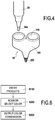
- the ink mixing assembly in Fig. 4 is similar to the ink mixing assemblies in Figs. 1-3 . Therefore, the detailed description of similar features will be omitted and like reference numerals will be used.
- An ink discharge device 30 may include a tip 34a, which may be felt.
- the tip 34a may be configured to deposit ink onto a writing surface.
- the casing 100 may be a polymer of any other suitable material, for example, metal.
- the casing 100 may or may not comprise a pressure regulation assembly having a discharge device receiver 300 and a spring 400.
- the user receives the benefit that felt tip discharge devices 30 are able to be effectively converted into a plastic tip writing instrument.
- the ink mixing assembly in Fig. 5 is similar to the ink mixing assemblies in Figs. 1-4 except that the discharge devices 40 may include an angled tip 44a and the ink linking assembly is configured to accommodate the angled discharge devices 40. Therefore, the detailed description of similar features will be omitted and like reference numerals will be used.
- An ink discharge device 40 may have a center axis E, and end 42 and an elongated ink transfer element 44 having a tip 24a, which may be felt.
- the tip 24a may be configured to deposit ink onto a writing surface.
- the end 42 may be angled relative to the center axis E such that the ink transfer element 44 is positioned at an angle ⁇ relative to the center axis C of the porous color linker 200.
- the angle ⁇ ⁇ may be within a range that positions the center axis E of the discharge device 40 to be parallel or substantially parallel with the center axis C of the porous color linker 200.
- the base portion B of the porous color linker may only one receiving portion 224 configured to receive the tips 44a of the first and second ink discharge devices 40.
- the receiving portion 224 may have a dimension x such that the tips 44a of different discharges devices 40 are separated from each other to prevent the occurrence of backflow or contaminating a discharge device 40 with the incorrect ink.
- the ink mixing assembly and discharge devices are more compact. As such, it facilitates the user's manipulation of the ink mixing assembly and discharge devices. Additionally, the shorter distance x and single receiving portion 224, enhances the porous color linker's ability to mix the multiple inks.
- the operation of the porous color linker 200 remains the same as the porous color linker 200 of Figs. 1-4 . That is, the ink is transferred to the base portion B, mixing portion M, and tip portion T by capillary action.
- the tip portion T may be configured to deposit indicia, or the mixed ink, on a writing surface.
- Fig. 6 shows a flow chart showing a method of mixing colors. It is envisioned that the casing 100 of any of the aforementioned embodiments may be configured to work with a digital application that assists the user in discovering which mixtures of ink result in a particular color, for example, red and yellow ink result in an orange color or yellow and blue ink result in a green color.
- the ink mixing assembly 10 may be of a digital type connected to a digital device or directly to the Internet Of Things (IOT) through a wireless connection allowing and advising the user on how to mix different discharge devices, for example, felt pens. Therefore, the ink mixing assembly may include a camera, processing unit, control unit, and transmitter.
- IOT Internet Of Things
- the ink mixing assembly 10 may be communicatively connected to the transmitter, and/or communicatively connected via a hardwire connection to an interface unit, which may be, for example a computer or mobile device.
- the camera may be configured to capture image information
- the processing unit may be configured to process the image information
- the control unit may be configured to send the image information via the transmitter.
- Communication technologies used by the ink mixing assembly to transmit information may include cellular, satellite, Bluetooth, low-power wide-area networks (LPWAN), or connecting directly to the internet via ethernet, which examples are not limiting.
- the information received by the user device can be routed to the application which may provide a suggestion of ink combinations to reproduce the color information captured by the camera.
- the application may or may not be connected to an IoT gateway. If connected, the image information may be routed to a user platform. Based on the image information, the application or user platform can provide appropriate suggestions or feedback on the captured image information.
- the user first enters into the application which products are being used, for example, the model of the ink mixing assembly and the series of ink discharge devices, for example ink markers.
- the user can either select a color on the application and receive a suggestion on the mixture of inks to use with the ink mixing assembly or the user may use the camera on the device to capture image data, send the data to the application, and allow the application the suggest the mixture of inks to use with the ink mixing assembly to reproduce the captured image data.
- the user follows the suggestion by the application by arranging the appropriate ink discharge devices into the ink mixing assembly and outputs or deposits the mixed ink on a writing surface.
Landscapes
- Engineering & Computer Science (AREA)
- Mechanical Engineering (AREA)
- Pens And Brushes (AREA)
Abstract
Description
- The following description relates to a porous color linker, and more particularly to porous color linker configured to mix inks and deposit the mixed ink onto a writing surface.
- Conventional mixable ink systems that allow a user to use one writing instrument while having the ability to use different colors of ink typically use a replaceable and/or refillable ink cartridge. A refillable ink cartridge can be attached to a separate device having a plurality of reservoirs of ink. The cartridge can be filled with a custom combination of inks to achieve a desired color and then cartridge may be inserted into the writing instrument. See, for example,
WO 2019/077262 . - A common drawback of conventional ink mixing systems is that they are complex and difficult to use. Additionally, they have a lot of components and can be expensive.
- The present disclosure provides a porous color linker comprising a tip portion configured to deposit indicia on a writing surface; a mixing portion configured to combine a plurality of inks; and a base portion having a first receiving portion configured to receive a tip of a first ink discharge device and a second receiving portion configured to receive a tip of a second ink discharge device.
- The capillary action of the porous color mixer is superior to a conventional plastic tip. The porous color mixer can adequately mix multiple colors together and due to the capillary action of the porous color mixer, it is superior to a conventional plastic tip at mixing colors and depositing the mixed ink. Additionally, this configuration reduces the risk of back pollution, e.g. color form one marker enters into the other marker.
- The porous color linker may comprise sintered plastic.
- The porous color linker may be washable.
- The porous color linker may have a pore size within a range of 2 to 150 microns.
- The distance between the tip interface and final tip end of the porous color linker may be in a range of 4 to 12 mm.
- The top portion of the porous color linker may be tapered between the tip interface and final tip end.
- The cross-section of the tip portion may have a circular shape.
- The cross-section of the tip portion may have a rectangular shape.
- In some embodiments, an ink mixing assembly comprises the aforementioned porous color linker and a casing attached to the base portion of the porous color linker. The casing is configured to receive a first ink discharge device and a second ink discharge device.
- The casing may be configured to hold a tip of the first ink discharge device into the first receiving portion of the porous color linker and is further configured to hold a tip of the second ink discharge device into the second receiving portion of the porous color linker.
- The above summary is not intended to describe each and every implementation of the concept. In particular, selected features of any illustrative embodiment within this disclosure may be incorporated into additional embodiments unless clearly stated to the contrary.
- The disclosure may be more completely understood in consideration of the following detailed description of aspects of the disclosure in connection with the accompanying drawings, in which:
-
Fig. 1 details an ink mixing assembly according to a first aspect. -
Fig. 2 details a cross-section of the ink mixing assembly ofFig. 1 . -
Fig. 3 details a cross-section of the porous color linker according to a second aspect. -
Fig. 4 details an ink mixing assembly according to a third aspect. -
Fig. 5 details a cross-section of the porous color linker according to a fourth aspect. -
Fig. 6 details a flow chart for a method of mixing colors. -
Fig. 1 shows anink mixing assembly 10. Theink mixing assembly 10 may be configured to mix two or more inks. The inks may be contained withinink discharge devices 20. Anink discharge device 20 may be, for example, a color marker. Although theink mixing assembly 10 shown includes 2ink discharge devices 20, theink mixing assembly 10 may be configured to receive more than twoink discharge devices 20. -
Fig. 2 shows a cross-section of theink mixing assembly 10 having twoink discharge devices 20. Theink mixing assembly 10 may include acasing 100 and a porous color linker 200. - An
ink discharge device 20 may include abarrel 21 which encloses anink 22 therein. Theink 22 may be in contact with anink transfer element 24. Theink transfer element 24 may include atip 24a, which may be plastic. Thetip 24a may be configured to deposit ink onto a writing surface. A writing surface, may be, for example, a piece of paper, cardboard, or any other surface where the ink may be deposited. - The
casing 100 may be a polymer of any other suitable material, for example, metal. Thecasing 100 may haveopenings 110 that are configured to receive anink discharge device 20. Theopenings 110 of thecasing 100 may be configured to secure a respectiveink discharge device 20 to thecasing 100 such that thetip 24a is securely contacting a respective first or second receivingportion 224 of the porous color linker 200. - The porous color linker 200 may be formed of a sintered polymer. The porous color linker 200 may be washable and reusable. The average pore size of the pores formed in the porous color linker may be within a range of 2 to 150 microns. The porous color linker 200 may include a tip portion T, mixing portion M, and base portion B.
- The base portion B may include a first receiving
portion 224 configured to receive atip 24a of a firstink discharge device 20 and a second receivingportion 224 configured to receive atip 24a of a secondink discharge device 20. The ink that is in the first and secondink discharges devices 20 may to transferred to the base portion B by capillary action in the flow direction F. The base portion B may be defined as the portion of the porous color linker 200 from surface Bi which is disposed within thecasing 100 and in contact with at least one of theink discharge devices 20 to the mixing interface BM where the mixing portion M begins. - The ink then may be transferred into the mixing portion M. The mixing portion M may be configured to combine and mix the plurality of inks drawn from the base portion B. The mixing portion M may be defined as the portion of the porous color linker 200 between the mixing interface BM and the tip interface MT. The mixing portion M has a first tapering toward a center axis C in order to mix the different inks, make a more concentrated ink, and prevent backflow of an incorrect ink color into the first and second
ink discharge devices 20. - Thereafter, the mixed ink may be transferred into the tip portion T. The tip portion T may be configured to deposit indicia, or the mixed ink, on a writing surface. The tip portion T has a second tapering toward the center axis C, that is less than the first tapering of the mixed portion M. This second tapering is configured to create a concentrated ink. The height D1 of the tip portion T may be greater than the width of the tip portion T. The height D1 may be in a range of 4 to 12 mm. The tip portion may be defined as the portion of the porous color mixer between the tip interface MT and the final end of the tip Tf. A cross-section of the tip taken along plane A-A may be circular. However, it is envisioned that the cross-section may be oval or rectangular.
- The ink mixing assembly in
Fig. 3 is the same as the ink mixing assembly inFigs. 1-2 except for a pressure regulation assembly. Therefore, the detailed description of similar features will be omitted and like reference numerals will be used. - An
ink discharge device 20 may include atip 24a, which may be plastic. Thetip 24a may be configured to deposit ink onto a writing surface. - The
casing 100 may be a polymer of any other suitable material, for example, metal. Thecasing 100 may comprise a pressure regulation assembly having adischarge device receiver 300 and aspring 400. Thecasing 100 may be formed with alip 120 positioned about theopening 110 and extends radially inward. - The
discharge device receiver 300 may be dimensioned to enclose the outer circumference of thedischarge device 20, but allow thetip 24a to contact a respective first or second receivingportion 224 of theporous color linker 200. Thedischarge device receiver 300 may have a substantially cylindrical shape and include an inner surface Ri and an outer surface Ro. - The inner surface Ri of the
discharge device receiver 300 may include a securingmember 334. The securingmember 334 may be formed as a protuberance, a plurality of protuberances, or a recess. - The
discharge device 20 may include a fixingmember 26 formed on the outer surface thereof. The fixingmember 26 may be configured to contact the securingmember 334. The fixingmember 26 may be formed as a protuberance, a plurality of protuberances, or a recess so long as it is formed to correspond with the securingmember 334 to fix thedischarge device 20 into thedischarge device receiver 300. - The
discharge device receiver 300 may comprise one or more flange(s) 332 formed on the outer surface Ro thereof. Theflange 332 may be dimensioned to extend from the outer surface Ro of the discharge receivedevice 300 and be enclosed within thecasing 100 such that thedischarge receiving device 300 is moveable relative to thecasing 100. - The pressure regulation comprised a
spring 400. Thespring 400 maybe positioned about the outer surface Ro of thedischarge receiving device 300 and between theflange 332 andlip 120 of the casing. In this configuration, thespring 400 may apply a pressure on thedischarge receiving device 300. Thespring 400 may be formed as a helical spring. The spring may comprise any suitable material, for example metal or plastic. - In operation, a user may insert a
discharge device 20 into thedischarge receiving device 300. Thedischarge device 20 may be operably fixed to thedischarge receiving device 300 due to the contact between the securingmember 334 and the fixingmember 26. Due to the pressure exerted by thespring 400 on the discharge receiving device, thetip 24a of thedischarge device 20 is held into place in the receivingportion 224 of theporous color linker 200. Further, due to the contact between the securingmember 334 and the fixingmember 26, thespring 400 may be maintained in a compressed configuration. In this configuration, the ink mixing assembly provides a consistent contact between thetip 24a of thedischarge device 20 and theporous color linker 200. This permits a consistent flow of ink while also reducing the occurrence of damage of thetip 24a of thedischarge device 20. - Similar to the
porous color linker 200 ofFig. 2 , the ink that is in thedischarge device 20 may be to transferred to the base portion B, mixing portion M, and tip portion T by capillary action. The tip portion T may be configured to deposit indicia, or the mixed ink, on a writing surface. - The ink mixing assembly in
Fig. 4 is similar to the ink mixing assemblies inFigs. 1-3 . Therefore, the detailed description of similar features will be omitted and like reference numerals will be used. - An
ink discharge device 30 may include atip 34a, which may be felt. Thetip 34a may be configured to deposit ink onto a writing surface. - The
casing 100 may be a polymer of any other suitable material, for example, metal. Thecasing 100 may or may not comprise a pressure regulation assembly having adischarge device receiver 300 and aspring 400. - In this configuration, the user receives the benefit that felt
tip discharge devices 30 are able to be effectively converted into a plastic tip writing instrument. - The ink mixing assembly in
Fig. 5 is similar to the ink mixing assemblies inFigs. 1-4 except that thedischarge devices 40 may include anangled tip 44a and the ink linking assembly is configured to accommodate theangled discharge devices 40. Therefore, the detailed description of similar features will be omitted and like reference numerals will be used. - An
ink discharge device 40 may have a center axis E, and end 42 and an elongatedink transfer element 44 having atip 24a, which may be felt. Thetip 24a may be configured to deposit ink onto a writing surface. - The
end 42 may be angled relative to the center axis E such that theink transfer element 44 is positioned at an angle ±θ relative to the center axis C of theporous color linker 200. The angle ± θ may be within a range that positions the center axis E of thedischarge device 40 to be parallel or substantially parallel with the center axis C of theporous color linker 200. - To account for the
angled tips 44a of thedischarge devices 40, the base portion B of the porous color linker may only one receivingportion 224 configured to receive thetips 44a of the first and secondink discharge devices 40. The receivingportion 224 may have a dimension x such that thetips 44a ofdifferent discharges devices 40 are separated from each other to prevent the occurrence of backflow or contaminating adischarge device 40 with the incorrect ink. - The benefit of this configuration is that by angling the
tips 44a of thedischarge devices 40 such that the axis E ofdischarge devices 40 are parallel or substantially parallel to the center axis C of theporous color linker 200, the ink mixing assembly and discharge devices are more compact. As such, it facilitates the user's manipulation of the ink mixing assembly and discharge devices. Additionally, the shorter distance x andsingle receiving portion 224, enhances the porous color linker's ability to mix the multiple inks. - The operation of the
porous color linker 200 remains the same as theporous color linker 200 ofFigs. 1-4 . That is, the ink is transferred to the base portion B, mixing portion M, and tip portion T by capillary action. The tip portion T may be configured to deposit indicia, or the mixed ink, on a writing surface. -
Fig. 6 shows a flow chart showing a method of mixing colors. It is envisioned that thecasing 100 of any of the aforementioned embodiments may be configured to work with a digital application that assists the user in discovering which mixtures of ink result in a particular color, for example, red and yellow ink result in an orange color or yellow and blue ink result in a green color. - As such, the
ink mixing assembly 10 may be of a digital type connected to a digital device or directly to the Internet Of Things (IOT) through a wireless connection allowing and advising the user on how to mix different discharge devices, for example, felt pens. Therefore, the ink mixing assembly may include a camera, processing unit, control unit, and transmitter. - The
ink mixing assembly 10 may be communicatively connected to the transmitter, and/or communicatively connected via a hardwire connection to an interface unit, which may be, for example a computer or mobile device. - In one communication path, the camera may be configured to capture image information, the processing unit may be configured to process the image information, and the control unit may be configured to send the image information via the transmitter. Communication technologies used by the ink mixing assembly to transmit information may include cellular, satellite, Bluetooth, low-power wide-area networks (LPWAN), or connecting directly to the internet via ethernet, which examples are not limiting.
- The information received by the user device can be routed to the application which may provide a suggestion of ink combinations to reproduce the color information captured by the camera. The application may or may not be connected to an IoT gateway. If connected, the image information may be routed to a user platform. Based on the image information, the application or user platform can provide appropriate suggestions or feedback on the captured image information.
- As shown in S100, the user first enters into the application which products are being used, for example, the model of the ink mixing assembly and the series of ink discharge devices, for example ink markers. As shown in S200, the user can either select a color on the application and receive a suggestion on the mixture of inks to use with the ink mixing assembly or the user may use the camera on the device to capture image data, send the data to the application, and allow the application the suggest the mixture of inks to use with the ink mixing assembly to reproduce the captured image data. In S300, the user follows the suggestion by the application by arranging the appropriate ink discharge devices into the ink mixing assembly and outputs or deposits the mixed ink on a writing surface.
- Throughout the description, including the claims, the term "comprising a" should be understood as being synonymous with "comprising at least one" unless otherwise stated. In addition, any range set forth in the description, including the claims should be understood as including its end value(s) unless otherwise stated. Specific values for described elements should be understood to be within accepted manufacturing or industry tolerances known to one of skill in the art, and any use of the terms "substantially" and/or "approximately" and/or "generally" should be understood to mean falling within such accepted tolerances.
- Although the present disclosure herein has been described with reference to particular embodiments, it is to be understood that these embodiments are merely illustrative of the principles and applications of the present disclosure. Additionally, any of the features of the described embodiments are combinable when not conflicting.
- It is intended that the specification and examples be considered as exemplary only, with a true scope of the disclosure being indicated by a fair reading of the following claims.
Claims (10)
- A porous color linker comprising :a tip portion configured to deposit indicia on a writing surface;a mixing portion configured to combine a plurality of inks; anda base portion having a first receiving portion configured to receive a tip of a first ink discharge device and a second receiving portion configured to receive a tip of a second ink discharge device.
- The porous color linker according to claim 1 comprises sintered plastic.
- The porous color linker according to claims 1 or 2 is washable.
- The porous color linker of any one of the preceding claims, wherein the pore size is within a range of 2 to 150 microns.
- The porous color linker of any one of the preceding claims, wherein the distance between the tip interface and final tip end is in a range of 4 to 12 mm.
- The porous color linker of any one of the preceding claims, wherein the top portion is tapered between the tip interface and final tip end.
- The porous color linker of any one of the preceding claims, wherein a cross-section of the tip portion has a circular shape.
- The porous color linker of any one of claims 1 - 6, wherein a cross-section of the tip portion has a rectangular shape.
- A ink mixing assembly comprising:the porous color linker of claims 1-8; anda casing attached to the base portion of the porous color linker, wherein the casing is configured to receive a first ink discharge device and a second ink discharge device.
- The ink mixing assembly of claim 9, wherein the casing is configured to hold a tip of the first ink discharge device into the first receiving portion of the porous color linker and is further configured to hold a tip of the second ink discharge device into the second receiving portion of the porous color linker.
Priority Applications (3)
| Application Number | Priority Date | Filing Date | Title |
|---|---|---|---|
| EP19184814.2A EP3760453A1 (en) | 2019-07-05 | 2019-07-05 | Porous color linker |
| US17/596,461 US12017472B2 (en) | 2019-07-05 | 2020-07-02 | Porous color linker |
| PCT/EP2020/068737 WO2021004905A1 (en) | 2019-07-05 | 2020-07-02 | Porous color linker |
Applications Claiming Priority (1)
| Application Number | Priority Date | Filing Date | Title |
|---|---|---|---|
| EP19184814.2A EP3760453A1 (en) | 2019-07-05 | 2019-07-05 | Porous color linker |
Publications (1)
| Publication Number | Publication Date |
|---|---|
| EP3760453A1 true EP3760453A1 (en) | 2021-01-06 |
Family
ID=67184943
Family Applications (1)
| Application Number | Title | Priority Date | Filing Date |
|---|---|---|---|
| EP19184814.2A Withdrawn EP3760453A1 (en) | 2019-07-05 | 2019-07-05 | Porous color linker |
Country Status (3)
| Country | Link |
|---|---|
| US (1) | US12017472B2 (en) |
| EP (1) | EP3760453A1 (en) |
| WO (1) | WO2021004905A1 (en) |
Cited By (1)
| Publication number | Priority date | Publication date | Assignee | Title |
|---|---|---|---|---|
| US11472219B2 (en) * | 2020-04-28 | 2022-10-18 | Crayola Llc | Wicking nib device and system |
Families Citing this family (1)
| Publication number | Priority date | Publication date | Assignee | Title |
|---|---|---|---|---|
| US11413901B1 (en) * | 2022-01-20 | 2022-08-16 | Mark Cuban | Palm pen |
Citations (3)
| Publication number | Priority date | Publication date | Assignee | Title |
|---|---|---|---|---|
| GB2277253A (en) * | 1993-04-20 | 1994-10-26 | Wu Hsien Jung | Marking pens capable of writing in more than one colour |
| US5388924A (en) * | 1994-02-07 | 1995-02-14 | Chao; Chung L. | Drawing pen having multiple side-matched absorptive drawing tips |
| WO2019077262A1 (en) | 2017-10-18 | 2019-04-25 | Societe Bic | Device for mixing inks, assembly comprising the device and the method for using same |
Family Cites Families (15)
| Publication number | Priority date | Publication date | Assignee | Title |
|---|---|---|---|---|
| US5368405A (en) | 1989-10-30 | 1994-11-29 | Sixiong; Xie | Non-mingling multicolor marker and its process |
| JP2679918B2 (en) | 1992-02-17 | 1997-11-19 | 二郎 堀 | Writing implement |
| US5440327A (en) | 1992-07-28 | 1995-08-08 | Calcomp Inc. | Polychromatic pen for pen plotters with color mixing at media surface |
| US5306092A (en) | 1993-05-05 | 1994-04-26 | Jenq Li Chen | Marking pen with gradual-layer color effect |
| CA2164331C (en) | 1994-08-09 | 1999-03-30 | Yasuo Ikeda | Writing implement |
| US5685224A (en) | 1995-08-18 | 1997-11-11 | Binney & Smith Inc. | Coloring device |
| NL1008489C1 (en) | 1998-03-05 | 1999-09-07 | Susan Shakerin | Five pens mounted together for musical notation |
| US5971643A (en) * | 1998-06-22 | 1999-10-26 | Ahmed; Cindy G. | Multiple cartridge rainbow pen |
| US7015901B2 (en) | 1999-10-25 | 2006-03-21 | Silverbrook Research Pty Ltd | Universal pen with code sensor |
| US6554517B2 (en) | 2001-07-19 | 2003-04-29 | Cynthia G. Ahmed | Multicolor marker |
| US6715950B2 (en) * | 2002-06-17 | 2004-04-06 | Allen C. Kim | Multi-color marking pen assembly |
| US7001091B1 (en) | 2003-10-31 | 2006-02-21 | Knight Andrew F | Ink pen for dispensing ink having time-dependent characteristics |
| CN2827748Y (en) | 2006-04-28 | 2006-10-18 | 王会加 | Two-color water color pencil |
| US9303820B2 (en) | 2008-10-14 | 2016-04-05 | Harris Richard Miller | Chemiluminescent aerosol spray |
| JP6903062B2 (en) * | 2016-01-25 | 2021-07-14 | ポレックス コーポレーション | Multi-element sintered porous liquid applicator nibs |
-
2019
- 2019-07-05 EP EP19184814.2A patent/EP3760453A1/en not_active Withdrawn
-
2020
- 2020-07-02 WO PCT/EP2020/068737 patent/WO2021004905A1/en not_active Ceased
- 2020-07-02 US US17/596,461 patent/US12017472B2/en active Active
Patent Citations (3)
| Publication number | Priority date | Publication date | Assignee | Title |
|---|---|---|---|---|
| GB2277253A (en) * | 1993-04-20 | 1994-10-26 | Wu Hsien Jung | Marking pens capable of writing in more than one colour |
| US5388924A (en) * | 1994-02-07 | 1995-02-14 | Chao; Chung L. | Drawing pen having multiple side-matched absorptive drawing tips |
| WO2019077262A1 (en) | 2017-10-18 | 2019-04-25 | Societe Bic | Device for mixing inks, assembly comprising the device and the method for using same |
Cited By (1)
| Publication number | Priority date | Publication date | Assignee | Title |
|---|---|---|---|---|
| US11472219B2 (en) * | 2020-04-28 | 2022-10-18 | Crayola Llc | Wicking nib device and system |
Also Published As
| Publication number | Publication date |
|---|---|
| US12017472B2 (en) | 2024-06-25 |
| WO2021004905A1 (en) | 2021-01-14 |
| US20220234379A1 (en) | 2022-07-28 |
Similar Documents
| Publication | Publication Date | Title |
|---|---|---|
| US12017472B2 (en) | Porous color linker | |
| EP0630326B1 (en) | Nib units for pens | |
| US20030006310A1 (en) | Liquid supply assembly | |
| US6536687B1 (en) | Mixing cup adapting assembly | |
| EP0446371B1 (en) | Writing utensil | |
| CA2375801A1 (en) | Printer cartridge with binder | |
| US5971643A (en) | Multiple cartridge rainbow pen | |
| WO2006081499B1 (en) | Connector systems and marker systems comprising same | |
| US4054093A (en) | Self-inking hand stamp | |
| US20150151565A1 (en) | Writing instrument | |
| US6276860B1 (en) | Liquid applicator | |
| US20060244805A1 (en) | Multicolor pen | |
| US20210016595A1 (en) | Writing method and apparatus | |
| TW200513503A (en) | Water-based pigment dispersion liquid for inkjet recording, ink composition for inkjet recording, and method for producing the water-based pigment dispersion liquid | |
| US9211720B2 (en) | Fluid container having first and second key set | |
| US12036814B2 (en) | Color linker | |
| CN106515266B (en) | A kind of intelligent pastel | |
| EP1520708A3 (en) | Set of ink cartridges, ink cartridge and ink jet printer | |
| US10300733B1 (en) | Writing instrument with spool valve | |
| US9862224B1 (en) | Writing instrument with spool valve | |
| WO2005081639A1 (en) | Toner for electrostatic charge image development | |
| WO2005081639A3 (en) | Toner for electrostatic charge image development | |
| CN224038623U (en) | Pencil lead storage box | |
| CN218813112U (en) | Road construction line marking machine | |
| CN216737619U (en) | Water distributor |
Legal Events
| Date | Code | Title | Description |
|---|---|---|---|
| PUAI | Public reference made under article 153(3) epc to a published international application that has entered the european phase |
Free format text: ORIGINAL CODE: 0009012 |
|
| STAA | Information on the status of an ep patent application or granted ep patent |
Free format text: STATUS: THE APPLICATION HAS BEEN PUBLISHED |
|
| AK | Designated contracting states |
Kind code of ref document: A1 Designated state(s): AL AT BE BG CH CY CZ DE DK EE ES FI FR GB GR HR HU IE IS IT LI LT LU LV MC MK MT NL NO PL PT RO RS SE SI SK SM TR |
|
| AX | Request for extension of the european patent |
Extension state: BA ME |
|
| STAA | Information on the status of an ep patent application or granted ep patent |
Free format text: STATUS: REQUEST FOR EXAMINATION WAS MADE |
|
| 17P | Request for examination filed |
Effective date: 20210706 |
|
| RBV | Designated contracting states (corrected) |
Designated state(s): AL AT BE BG CH CY CZ DE DK EE ES FI FR GB GR HR HU IE IS IT LI LT LU LV MC MK MT NL NO PL PT RO RS SE SI SK SM TR |
|
| RAP3 | Party data changed (applicant data changed or rights of an application transferred) |
Owner name: SOCIETE BIC |
|
| STAA | Information on the status of an ep patent application or granted ep patent |
Free format text: STATUS: EXAMINATION IS IN PROGRESS |
|
| 17Q | First examination report despatched |
Effective date: 20221219 |
|
| STAA | Information on the status of an ep patent application or granted ep patent |
Free format text: STATUS: THE APPLICATION IS DEEMED TO BE WITHDRAWN |
|
| 18D | Application deemed to be withdrawn |
Effective date: 20250830 |